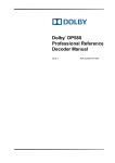
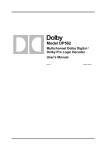
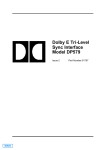
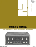
1
Dolby Laboratories
USA
100 Potrero Avenue
San Francisco CA 94103-4813
Telephone 415-558-0200
Facsimile 415-863-1373
UK
Wootton Bassett
Wiltshire SN4 8QJ
Telephone (44) 1793-842100
Facsimile (44) 1793-842101
Model 740
Web: www.dolby.com
Spectral Processor
LD
EQUALIZATION
Side Chain
In
10
300
150
0
dB
40
20
75
Low
Low
Hz
A
’
Users’ Manual
MAIN
Users’ Manual
For
Model 740
Spectral Processor
Dolby Laboratories Incorporated
U.S.A. 100 Potrero Avenue, San Francisco, CA 94103
Tel: 415-558-0200; Fax: 415-863-1373
U.K. Wootton Bassett, Wiltshire SN4 8QJ
Tel: (44) 1793-842100; Fax: (44) 1793-842101
Web: www.dolby.com
WARRANTY INFORMATION, USA: warranty on the product covered by this manual is subject to the limitations
and disclaimers set forth in the warranty disclaimer originally shipped with the product and also printed on the
back of the invoice.
All requests for repairs or information should include the unit serial number to assure rapid service.
Dolby and the double-D are registered trademarks of Dolby Laboratories.
©1997 Dolby Laboratories
ISSUE 3
S97/9575/11640
Part No. 91291
MAIN
+6
dB
Introduction ...................................................................... 1
Low-level Processing - a new idea .................................... 1
The Gain Elements ........................................................... 2
Combining Fixed and Sliding Bands .................................. 2
Multi-level Processing ....................................................... 2
Three-band EQUALIZATION Control ................................ 2
Source Noise Reduction ................................................... 3
4K
100
Out
8K
200
dB
-12
Filters
-6
Side
Chain
High
Out
Section 2
Specifications
Specifications ................................................................... 5
Section 3
Installation
Mid
Installation........................................................................ 9
Power Connections......................................................... 10
Audio Connections.......................................................... 11
For Balanced Systems .................................................... 11
For Unbalanced Systems ................................................ 11
Operating level ............................................................... 12
dB
Low
20
150
75
Hz
300
1k
600
0
dB
10
Side Chain
10
Section 4
Front-panel Controls
Notes:
CHANNEL
-60
dB
-40
0
Input Clip
-50
EQUALIZATION
In
Active
THRESHOLD
Channel A
Title
Channel B
20
1k
500
2k
Hz
8k
4k
0
10
dB
20
Stereo Link
In
Eq
Out
In
SOURCE NR
Track
Date
Section 1
How it works
-14
Clip
OUTPUT
0
TABLE OF CONTENTS
Controls ......................................................................... 13
Threshold Section........................................................... 13
Equalization Section ....................................................... 14
Crossover Control........................................................... 14
Equalization Mode Switch ............................................... 15
i
MAIN
Source NR Section......................................................... 16
Filter Switches................................................................ 16
Output Level Control ...................................................... 17
Stereo Link Switch ......................................................... 18
Power LED..................................................................... 18
Section 5
Getting Started
NL
Some General Techniques ............................................. 20
“Extending” the frequency response ............................... 21
Emphasizing Mid-Range Frequencies ............................. 22
Bringing Out Ambience................................................... 23
Using the Source NR Section ......................................... 24
Using the Side Chain Output .......................................... 25
Section 6
Appendix A
Safety Notices................................................................ 27
Sheets for recording control settings .............................. 34
BELANGRIJK VEILIGHEIDS-VOORSCHRIFT:
Deze unit voldoet aan de IEC65 veiligheids-standaards. Voor een
veilig gebruik en om het gevaar van electrische schokken en het risico
van brand te vermijden, dienen de volgende regels in acht te worden
genomen:
o
Controleer of de spanningscaroussel op het juiste
Voltage staat.
o
Gebruik alleen zekeringen van de aangegeven typen
en waarden.
o
Aansluiting van de unit alleen aan een geaarde
wandcontactdoos.
o
De netkabel die met de unit wordt geleverd, moet als
volgt worden aangesloten:
Fase
Nul
Aarde
ii
Bruin
Blauw
Groen/Geel
33
MAIN
SECTION 1
HOW IT WORKS
Introduction
S
The Dolby Model 740 Spectral Processor is a unique two-channel
dynamic equalizer that allows the creative recording engineer to bring
out the low-level detail without affecting louder signals or transients. At
the heart of the Spectral Processor is a complex multi-band processor,
though the unit itself is very easy to use. Refer to the block diagram
located at the end of this Section.
VIKTIGA SÄKERHETSÅTGÄRDER!
Denna enhet uppfyller säkerhetsstandard IEC65. För att garantera
säkerheten och gardera mot eventuell elchock eller brandrisk, måste
följande observeras:
o
Kontrollera att spänningsväljaren är inställd på korrekt
nätspänning.
o
Konrollera att säkringarna är av rätt typ och för rätt
strömstyrka så som anvisningarna på enheten
föreskriver.
Low-level Processing - a new idea
The Spectral Processor works by boosting all low-level information
using a sophisticated processing stage. This boosted signal is then
passed to a three-band equalizer section to allow the user to select the
appropriate parts of the spectrum. The output of the equalizer is then
added to the original untreated signal (as shown below) so that the
output of the Spectral Processor consists of a signal where the lowlevel detail is enhanced but high-level signals remain unaltered.
Boosted low-level signals
PROCESSOR
o
o
Enheten måste vara jordad genom anslutning till ett
korrekt kopplat och jordat el-uttag.
Boosts all
low-level signals
High-level
signals
attenuated
El-sladden som medföljer denna enhet måste kopplas
enligt foljande:
Fas
Neutral
Jord
Brun
Blå
Grön/Gul
EQUALIZATION
High
Mid
+
Low
+
INPUT
Original untreated signal
The key to producing a signal that sounds quite natural (even though
the low-level signals have been increased by up to 20 dB) is in the
design of the processing stage.
32
1
MAIN
There are 3 notable aspects to this processing stage:
x The gain elements - fixed and sliding bands
x How these elements are combined
x A multi-level approach
The Gain Elements - fixed bands and sliding bands
The processing stage actually contains eight processors that partition
the incoming signal in terms of both frequency and level. These
processors work in pairs of one fixed-band stage and one sliding-band
stage. The sliding bands provide a constant amount of boost in a
frequency band that can slide up and down the audio spectrum while
the fixed bands provide a variable amount of boost in bands which are
fixed in frequency. The optimum boost for some signals may be
provided by a sliding-band processor, whereas for another signal a
fixed-band processor may be better.
Combining Fixed and Sliding Bands
The key to the processing is how these bands work together; their
outputs are combined in a unique way to gain the benefits of both
approaches without the drawbacks of either. For any part of the
spectrum the output of the band that provides the most boost is used,
resulting in great flexibility in boosting low-level elements.
Multi-level Processing
There are four of these fixed-band/sliding-band pairs, two for high
frequencies and two for low frequencies. Within each frequency range
the pairs of bands are arranged so that one pair boosts low-level
signals, reducing its gain to unity at medium levels where the second
pair takes over, providing boost for low-level and medium-level signals
gradually reducing its gain to unity at around 0 VU. The two pairs of
bands combine to create a smooth transition from a gain of more than
20 dB at low levels to unity gain at high levels. This combination not
only doubles the processing effect but also doubles the steepness of
the filter slopes where the signal requires it, improving the
discrimination between boosted and non-boosted areas of the
spectrum.
Three-band EQUALIZATION Control
E
AVISO IMPORTANTE DE SEGURIDAD
Esta unidad cumple con la norma de seguridad IEC65. Para
asegurarse un funcionamiento seguro y prevenir cualquier posible
peligro de descarga o riesgo de incendio, se han de observar
las siguientes precauciones:
o
Asegúrese que el selector de tensión esté ajustado a
la tensión correcta para su alimentación.
o
Asegúrese que los fusibles colocados son del tipo y
valor correctos, tal como se marca en la unidad.
o
La unidad debe ser puesta a tierra, conectándola a
un conector de red correctamente cableado y puesto
a tierra.
o
El cable de red suministrado con esta unidad, debe
ser cableado como sigue:
Vivo
Neutro
Tierra
Marrón
Azul
Verde/Amarillo
The processor stage in the Spectral Processor boosts all low-level
signals across the entire audio spectrum. The equalization section
divides the low-level spectrum into three variable bands allowing the
user to select which parts of the low-level signal they wish to
2
31
MAIN
enhance. The selected signals then pass on to the summing stage
where they are added to the original untreated signal.
The EQUALIZATION section is similar to a three-way loudspeaker
crossover network. Low, Mid and High controls set the amount of
boost in their respective bands while two crossover controls set the
crossover frequencies between the Low, Mid, and High bands.
Source Noise Reduction
I
NORME DI SICUREZZA – IMPORTANTE
Questa apparecchiatura è stata costruita in accordo alle norme di
sicurezza IEC 65. Per una perfetta sicurezza ed al fine di evitare
eventuali rischi di scossa êlettrica o d'incendio vanno osservate le
seguenti misure di sicurezza:
o
Assicurarsi che il selettore di cambio tensione sia
posizionato sul valore corretto.
o
Assicurarsi che la portata ed il tipo di fusibili siano
quelli prescritti dalla casa costruttrice.
o
L'apparecchiatura deve avere un collegamento di
messa a terra ben eseguito; anche la connessione
rete deve avere un collegamento a terra.
o
Il cavo di alimentazione a corredo
dell'apparecchiatura deve essere collegato come
segue:
Filo tensione
Neutro
Massa
The Spectral Processor boosts low-level signals while leaving highlevel signals relatively unchanged. It can be thought of as an “audio
magnifying glass” which “magnifies” detail in selectable areas of the
spectrum.
A side effect of this “magnification” is that some of the details that are
magnified may be undesirable -- the most common unwanted detail
which may be revealed is noise.
For this reason each channel contains a “source-noise reduction” or
“SOURCE NR” section. This SOURCE NR section uses a sliding-band
technique that can reduce noise present in the input signal by up to 12
dB. Selectable high-frequency and low-frequency side-chain filters are
also provided to prevent unwanted signals from entering the low level
processing stage.
Marrone
Blu
Verde/Giallo
30
3
MAIN
METER
LOW
THRESHOLD
SIDECHAIN
+
D
WICHTIGER SICHERHEITSHINWEIS
o
o
o
Das mitgelieferte Netzkabel muß wie folgt verdrahtet
werden:
Die Erdung des Gerätes muß über eine geerdete
Steckdose gewährleistet sein.
Die Sicherungen müssen in Type und Stromwert mit
den Angaben auf dem Gerät übereinstimmen.
Der Spannungswähler muß auf Ihre Netzspannung
eingestellt sein.
Dieses Gerät entspricht der Sicherheitsnorm IEC65. Für das sichere
Funktionieren des Gerätes und zur Unfallverhütung (elektrischer
Schlag, Feuer) sind die folgenden Regeln unbedingt einzuhalten:
o
Phase
Nulleiter
Erde
29
braun
blau
grün/gelb
MAIN
+
MID
8 BAND
PROCESSOR
HIGH
EQ
SOURCE-NOISE
REDUCTION
OUTPUT
IN
INPUT
OUT
Audio Path
Control Path
SPECTRAL PROCESSOR BLOCK DIAGRAM (ONE CHANNEL)
SECTION 2
SPECIFICATIONS
Specifications
Layout
1-U high unit containing two independent channels of Spectral
Processing. Stereo-link switch for use with stereo material.
F
IMPORTANT – NOTE DE SECURITE
Ce materiel est conforme à la norme IEC65. Pour vous assurer d'un
fonctionnement sans danger et de prévenir tout choc électrique ou tout
risque d'incendie, veillez à observer les recommandations suivantes.
Operating levels
Switch on rear of unit selects between High (+4 dBu) and Low (-6 dBu)
line-level operation.
Maximum input levels
High +24 dBu, Low + 14 dBu.
Maximum output levels
High + 26 dBu, Low + 20 dBu. Input and output clip LEDs indicate
when maximum levels have been exceeded.
o
Le selecteur de tension doit être placé sur la valeur
correspondante à votre alimentation réseau.
Inputs
o
Les fusibles doivent correspondre à la valeur indiquée
sur le materiel.
Outputs
o
Le materiel doit être correctement relié à la terre.
o
Le cordon secteur livré avec le materiel doit être
cablé de la manière suivante:
Since both the inputs and outputs of the Spectral Processor are floating
and the unit maintains the polarity of the input signal it is unimportant
which XLR wiring convention is used. In the interests of international
standardization we recommend that the current IEC convention (pin 2
“high/hot” pin 3 “low/cold”) is used.
Phase
Neutre
Terre
Brun
Bleu
Vert/Jaune
28
3-pin female XLR connector. Balanced, floating, 10 kohm approx.
3-pin male XLR connector. Balanced, floating, 20 ohm approx.
Threshold
Processing threshold adjustable between 60 dB and 40 dB below the
nominal operating level. Five-LED meter indicates processor activity.
5
MAIN
Equalization section
SECTION 6
APPENDIX A
Three-band filter section with adjustable cross-over frequencies
between sections. Low - Mid crossover adjustable from 75 Hz to
1 kHz. Mid - High 500 Hz to 8 kHz. Maximum boost of low level
signals in each section: greater than 20 dB - crossover controls set to
300 Hz and 2 kHz.
Source NR
Sliding band noise reduction section reduces noise present in the input
signal by up to 12 dB. Selectable high- and low-frequency side-chain
filters prevent unwanted signals from entering the low-level processing
stage.
Output
Overall channel gain, with processing out, adjustable from -14 dB to
+6 dB.
GB
IMPORTANT SAFETY NOTICE
This unit complies with the safety standard IEC65. To ensure safe
operation and to guard against potential shock hazard or risk of fire,
the following must be observed:-
Output noise (CCIR/ARM) relative to operating level
EQ section out: High - Less than -88 dB. Low - Less than -82 dB
EQ controls set to maximum: High - Less than -60 dB Low - Less than
-60 dB
o
If the unit has a voltage selector, ensure that it is set
to the correct mains voltage for your supply. If there
is no voltage selector, ensure that your supply is in
the correct range for the input requirement of the unit.
Total Harmonic Distortion
o
20 dB above operating level, 20 Hz - 20 kHz.
EQ out, Source NR out - Less than 0.1%.
EQ in, Source NR out - Less than 0.5%.
Ensure fuses fitted are the correct rating and type
as marked on the unit.
o
The unit must be earthed by connecting to a
correctly wired and earthed power outlet.
Dimensions
o
The power cord supplied with this unit must be wired
as follows:-
Dynamic Range
Greater than 108 dB
44 x 483 mm rack mounting (1.75 x 19"). Maximum projection behind
mounting surface 248 mm (9.76"), plus a further 65 mm (2.5") for the
connectors.
Power Required
User-selected voltage (50/60 Hz AC single-phase) nominally 100, 120,
220, 240 V, covering ranges 85-110, 102-132, 187-242 and 204-264 V.
Consumption 35 W maximum.
Live
Neutral
Earth
Brown
Blue
Green/Yellow
Weight
5.3 kg (11.6 lbs) approx.
6
27
MAIN
Operating Temp. Range
0 to 40 degrees C.
Power Status
A green LED indicates status: constant brightness indicates that all
power supply rails are present; flashing indicates a fault.
Note
0 dBu is defined as 0.775 V without regard to impedance
7
MAIN
Using the Source NR Section
With low-level tracks - solo acoustic instruments, woodwind, quiet
vocals - there may be little or no “useful” detail at the extremes of the
spectrum. In such cases, when the High or Low bands are turned up,
low-level background hiss or rumble may become audible.
This unwanted low level information can be reduced in two distinct
ways.
Low-frequency and high-frequency filters can be switched in to bandlimit the signal entering the low-level processing stage so that the
unwanted signals are not boosted. Note that these filters do not affect
the original audio signal, which is passed to the output without filtering
SECTION 3
INSTALLATION
Installation
Unpack the unit from its box and check for any damage. Be sure to
check the packing material for the power line cord and spare fuses.
Before mounting the unit in a rack or flight-case check the setting of
the voltage selector and that the appropriate fuse is fitted to the unit as
follows
Step 1
When the unwanted noise is similar in frequency to wanted low-level
details the Source NR control is a better solution. The source NR
circuit is a program-dependent sliding filter that moves down the signal
spectrum, reducing noise when there is no signal but sliding out of the
way when low-level information is present.
Using a small flat-bladed screwdriver, lever open the voltage
selector/fuse holder compartment door in the power supply
input connector. Rotate the voltage selector drum until it
reads the correct voltage for the installation. ( The drum
may also be removed from the housing and replaced with
the correct voltage displayed; it will only fit one way round.)
The Source NR can be used irrespective of the settings of the
Equalizer section. To use this section as a stand-alone noise reducer switch the EQ mode switch to In and set the Low, Mid and High
controls to minimum.
SPARE FUSE
(UPPER)
OCTAGONAL PEG
OPEN THE
DOOR
ROUND PEG
VOLTAGE SELECTOR
WHEEL
FUSE
ACTIVE
FUSE CARRIER
(LOWER)
FUSE
Step 2
24
A2F4037
Check that the correct value fuse is fitted.
9
MAIN
WARNING: To reduce the risk of fire, use the correct rating and type of fuse:
For 100/110V, use 500 mA ¼" x 1¼" slow-blow fuse
For 220/240 V, use T200 mA 5 x 20 mm time lag.
Close the compartment door making sure that it clicks firmly into place.
Bringing Out Ambience
Reverberation and ambience tend to have most audible effect at midfrequencies. The crossover controls on the Spectral Processor will
allow the width of the Mid band to be adjusted, and this can be used
very successfully to amplify any ambience present on a track.
Power Connections
Connect the power cable between the model 740 Spectral Processor
and the power outlet.
THRESHOLD
SEE SECTION 6 (APPENDIX A) FOR IMPORTANT INFORMATION
ON WIRING CONVENTIONS.
Side Chain
In
In
10
10
10
0
Input Clip
-50
300
150
0
-60
For some markets the unit is supplied with a three-wire power cord with a three-pin
polarized plug for connection to a power source and a safety ground (earth). The
ground terminal of the plug is directly connected to the chassis of the model 740. For
continued protection against electric shock, a three-pin power receptacle MUST be
used, and the ground wire MUST always be connected. DO NOT use a ground lifting
adaptor and NEVER cut the ground pin of a three-pin plug.
Connections For the United Kingdom:
dB
dB
Filters
2k
600
1k
0
20
dB
4k
20
0
dB
20
Eq
In
-40
Low
75
Hz
1k
Mid
500
Hz
8k
or coloured green or green and yellow.
The core which is coloured blue must be connected to the terminal
which is marked with the letter N or coloured black.
x
The core which is coloured brown must be connected to the
terminal which is marked with the letter L or coloured red.
10
-12
200
8K
-14
dB
+6
Out
100
4K
Notice that because of the way the Spectral Processor works, the
ambience will only tend to be brought up when there are no other
spectral components masking it. In this way, more ambience is
perceived on the track, yet the intelligibility of vocals or the clarity of the
instruments is not smeared by that ambience.
The core which is coloured green and yellow must be connected to
the terminal in the plug which is marked with the letter E or by the
x
Side
Chain
dB
The settings shown above cover a broad range useful in enhancing
ambience. Adjusting the spectral balance between Mid and High
allows the “color” of the ambience to be altered. The Threshold
adjustment is important in order to differentiate between lower level
ambience and higher level direct sound. Switching to Side Chain
mode can help in locating which parts of the ambience are being
boosted.
As the colours of the cores in the mains lead may not correspond with the
coloured markings identifying the terminals in your plug, proceed as follows:
earth symbol
High
Out
CHANNEL
WARNING: THIS APPARATUS MUST BE EARTHED
x
Clip
-6
Out
Note
OUTPUT
SOURCE NR
EQUALIZATION
Active
23
MAIN
Emphasizing Mid-Range Frequencies
Audio Connections
When detail is “buried” within a track, a useful technique is to use the
Mid band alone, sweeping the spectrum using the two crossover
controls together to locate the signal you want to boost.
Input and output connection to the Spectral Processor are made by
three-pin XLR connectors.
For Balanced Systems
Mixing Console
Model 740
Spectral Processor.
THRESHOLD
Side Chain
In
In
10
10
Active
10
Clip
-6
0
Input Clip
-50
300
150
0
dB
Filters
2k
600
1k
0
20
dB
4k
20
0
dB
20
Eq
In
Out
dB
-12
Out
-60
dB
+
OUTPUT
SOURCE NR
EQUALIZATION
-40
75
Low
Hz
1k
500
Mid
Hz
8k
High
200
8K
-14
dB
_
2
1
3
Ground
+6
Out
Side
Chain
100
4K
CHANNEL
Note shield connected
at one end only.
Adjust the Threshold so that the center green LED is lit most of the
time and set the Mid level control to 10. Switch the EQ mode switch to
Side Chain and sweep the two crossover controls up and down
together, keeping them at roughly the same angle. Though this may
seem to give a broad Mid frequency range, you will find that the
Spectral Processor selectively boosts only those details in that area
which are below the threshold.
Since both the inputs and outputs of the Spectral Processor are floating
and the unit maintains the polarity of the input signal it is unimportant
which XLR wiring convention is used. In the interests of international
standardization we recommend that the current IEC convention (pin 2
“high/hot” pin 3 “low/cold”) is used.
For Unbalanced Systems
Model 740
Spectral Processor.
Mixing Console
+
Ground
THRESHOLD
Side Chain
In
In
10
10
Active
10
300
150
0
3
-6
dB
Filters
2k
600
1k
0
20
dB
4k
20
0
dB
20
Eq
In
Out
dB
Clip
1
0
Input Clip
-50
-60
2
OUTPUT
SOURCE NR
EQUALIZATION
-40
Low
75
Hz
1k
Mid
500
Hz
8k
High
Side
Chain
Out
dB
-12
200
8K
-14
dB
+6
Note shield connected
at one end only.
Out
100
4K
CHANNEL
When the right area of the spectrum is located, re-adjust the Threshold
for best effect, then switch the EQ mode switch to In and adjust the
Mid control appropriately.
The outputs of the Spectral processor are both floating and balanced
and behave similarly to a transformer output stage. For use in
unbalanced systems the output signal should be taken from either pin 2
and pin 3 grounded or taken from pin 3 with pin 2 grounded. It is
immaterial which of these two methods is used provided the same
convention is used for all inputs and outputs.
Note: Connecting an unbalanced system between either pin 2 or 3 and
using pin 1 as ground will appear to work correctly but will give a
reduced signal to noise ratio and an incorrect frequency response.
22
11
MAIN
Operating level
“Extending” the frequency response
Set the line-level switch, located on the rear of the unit, to the
appropriate setting for your installation. If you use standard +4 dBm =
0 VU line levels set the switch to the “high (+4)” position. If you use
“-10” line levels use the “low (-6)” position. Some mixing consoles that
have +4 inputs and outputs may use -10 line levels for auxiliary
sends/returns, so it may be necessary to experiment to find the best
setting for your installation.
The Spectral Processor can be used to “brighten” or “deepen” an audio
track.
If you have selected the low line-level setting and the Input Clip LED
flashes frequently, try selecting the “high (+4)” setting. If you have
selected the high setting and find that you have to operate with the
THRESHOLD control fully clockwise all the time try selecting the “low (6)” position.
THRESHOLD
Side Chain
In
In
10
10
10
Clip
-6
0
Input Clip
-50
300
150
0
dB
Filters
2k
600
1k
0
20
dB
4k
20
0
dB
20
Eq
In
Out
dB
-12
Out
-60
dB
OUTPUT
SOURCE NR
EQUALIZATION
Active
-40
75
Low
Hz
1k
500
Mid
Hz
8k
High
200
8K
-14
dB
+6
Out
Side
Chain
100
4K
CHANNEL
Set the Threshold so that the center and left green LEDs are lit, and
use only the High band as you would a shelf equalizer. This will put a
very clean, very high “top” on a sound. For example; putting “air”
around vocals without bringing up sibilants, or bringing acoustic
instruments “closer”.
THRESHOLD
Side Chain
In
In
10
10
10
300
150
0
dB
Filters
2k
600
1k
0
20
dB
4k
20
0
dB
20
Eq
In
Out
dB
Clip
-6
0
Input Clip
-50
-60
OUTPUT
SOURCE NR
EQUALIZATION
Active
-40
Low
75
Hz
1k
Mid
500
Hz
8k
High
Side
Chain
Out
dB
-12
200
8K
-14
dB
+6
Out
100
4K
CHANNEL
Alternatively, with the Threshold control set to light predominantly the
center green LED, use the Low band only to add “depth” to the sound:
this is excellent for making the rhythm track “fatter” or to restore the LF
to a bass guitar that “has lost something” after being recorded at
30 ips.
Using both of the above techniques at the same time on a finished
stereo mix can extend the perceived frequency response, and is
capable of adding “sparkle” and “depth” to just about any track working
as an intelligent HiFi Loudness button.
12
21
MAIN
THRESHOLD
Side Chain
In
In
10
10
Active
10
300
150
0
-6
dB
Filters
2k
600
1k
0
20
dB
4k
20
0
dB
20
Eq
In
Out
dB
Clip
0
Input Clip
-50
-60
SECTION 4
FRONT-PANEL CONTROLS
OUTPUT
SOURCE NR
EQUALIZATION
-40
Low
75
Hz
1k
Mid
500
Hz
8k
High
Side
Chain
Out
dB
-12
200
8K
-14
dB
+6
Out
100
4K
CHANNEL
To get an understanding of the crossover controls try the following
example. While still in the Side Chain mode, listen to just one
frequency band, by turning down the levels in the other two. Alter the
Crossover frequencies to see how they affect each band. Note that the
Mid-band is affected by both upper and lower Crossovers.
Controls
The controls on the Spectral Processor affect the operation of the
signal processing section and are used to control when (in terms of
signal level) processing effects begin and end and where (in terms of
frequency) the effects will be heard. The Model 740 Spectral
Processor has two channels of processing that may be used
independently or as a stereo pair. Each channel is divided into four
sections: THRESHOLD, EQUALIZATION, SOURCE NR, and
OUTPUT.
THRESHOLD
Now switch between EQ In and EQ Out to hear the effect of adding
this Low-level detail to the main signal to create spectrally processed
audio.
Side Chain
In
In
10
10
10
300
150
0
dB
Filters
2k
600
1k
0
20
dB
4k
20
0
dB
20
Eq
In
Out
dB
Clip
-6
0
Input Clip
-50
-60
OUTPUT
SOURCE NR
EQUALIZATION
Active
-40
Low
75
Hz
1k
Mid
500
Hz
8k
High
Side
Chain
Out
dB
-12
200
8K
-14
dB
+6
Out
100
4K
CHANNEL A
Some General Techniques
The settings given in the following section are intended as a starting
point, from which new users should be able to:
x
Develop a feel for how best to use the processor on a
particular track.
THRESHOLD Section
The THRESHOLD control is used to control the level at which
processing effects begin.
THRESHOLD
x
Get some interesting and worthwhile results instantly.
Active
Input Clip
-50
-60
dB
-40
CHANNEL A
The threshold may be set from -60 dB to -40 dB
below 0 VU. A setting of -50 dB means that signals
below -50 dB will be boosted by 20 dB, signals
above -50 dB will receive progressively less boost,
reaching unity gain at around -10 dB. Turning the
control in a clockwise direction raises the threshold,
i.e. more of the signal will be fully boosted and the
Spectral Processor will have more effect on the
sound.
Above the threshold control is a 5-LED meter.
Normally, the threshold control should be adjusted so that the center
green LED is lit most often.
20
13
MAIN
If the left (orange) LED is lit most often then the signal level in the
processor is too low; both high-level and low-level signals will be
boosted by the processor which makes it act like a fixed-gain equalizer.
If a signal is constantly in the high portion of the meter (right side) the
processor will provide little boost to either low-level or high-level
signals.
The red “Input Clip” indicator will light if the input signal level from the
console is too high. The signal level should be reduced by turning
down the console send level to the Spectral Processor. If the console
send level looks reasonable then the line-level switch on the rear of the
Spectral processor may be incorrectly set to the low position.
EQUALIZATION Section
EQUALIZATION
Side Chain
In
10
10
10
300
150
0
dB
1k
0
dB
4k
20
0
dB
20
Hz
The Spectral Processor acts only on low-level signals, those below a
certain “Threshold”. Adjusting the Threshold control is possibly the
best way to appreciate how the Spectral Processor will affect sounds.
Switching the EQ to the Side Chain position can be particularly helpful
here, as the processed low-level signals are sent directly to the output,
enabling the user to hear very clearly where the processing is being
applied.
Eq
In
Out
Low
The Dolby Spectral Processor is a unique dynamic equalizer. It
unlocks new possibilities in audio sweetening, with effects ranging from
very subtle to very obvious. It acts like an equalizer that works on
signal details - boosting the low-level information present in the original
signal.
2k
600
20
75
SECTION 5
GETTING STARTED
1k
Mid
500
Hz
8k
High
Side
Chain
THRESHOLD
Side Chain
In
In
10
10
10
300
150
dB
Filters
2k
600
1k
0
20
dB
4k
20
0
dB
20
Eq
In
Out
Crossover Control
These two controls set the crossover frequencies between the High,
Mid, and Low bands, similar to the crossovers in a three-way
loudspeaker system. With the controls at their center detent position,
the crossover between the Low and Mid bands is at 300 Hz and the
crossover between the Mid and High is at 2 kHz. Note that the three
bands always cover the whole audio spectrum: such that, for example,
making the Mid band wider will simultaneously make the Low and High
14
-60
dB
Clip
-6
0
Input Clip
-50
0
Low, Mid, and High controls set the amount of boost applied to lowlevel signals in each of the three frequency bands. When a control is
fully counter-clockwise, no boost will be applied to the low-level signals
in that band. If the control is fully clockwise, low-level signals in that
band will be boosted by 20 dB. The Low, Mid, and High bands have
center frequencies of 80 Hz, 800 Hz, and 8 kHz respectively when the
crossover controls are in the center-detent position.
OUTPUT
SOURCE NR
EQUALIZATION
Active
-40
Low
75
Hz
1k
Mid
500
Hz
8k
High
Side
Chain
Out
dB
-12
200
8K
-14
dB
+6
Out
100
4K
CHANNEL
Switch to Side Chain, set the crossover controls to their detent position
of 300 Hz and 2 kHz and set the Low, Mid and High level controls to
10. Now sweep the Threshold control up and down and listen to how
the low-level “details” change. The audible signal in this mode is the
“effect” that will be “mixed” with the original input when the EQ mode
switch is switched to IN.
19
MAIN
Stereo Link Switch
Processor
740
Stereo Link
In
Out
The STEREO LINK switch allows the Spectral Processor
to be used on stereo programs without dynamically
shifting the left-right balance of the material. In this mode,
the higher control signal in each band of the multi-band
processor will control that band in both channels. If it is
more desirable to force one channel to be slaved to the
other, adjust the THRESHOLD control of the channel you
wish to be the slave so that it is fully clockwise.
Note that the STEREO LINK switch only affects the
operation of the low-level processing stage. The
EQUALIZATION and SOURCE NR controls are not
affected and are still independent and must be set
manually.
bands narrower. For this reason these controls are most effective
when the Low, Mid and High bands are set differently. If all bands are
at similar boost settings, the Crossover controls will be less effective.
EQUALIZATION Mode Switch
The Spectral Processor works by adding low-level signals boosted by
the processing stage to the original untreated signal. The Eq mode
switch selects three different processing modes: In, Out and Side
Chain.
IN - Spectral Processing is IN and active. The green IN
LED will light at the upper left corner of the section.
The output of the unit will be the sum of the original
signal and the boosted low-level signals selected by
the EQUALIZATION section.
OUT - Spectral Processing is bypassed and the signal is
passed unchanged. No LEDs in the equalization
section are lit in this mode.
Power LED
The POWER LED provides operational status for the unit
as follows;
Spectral P
Model 7
Power
OFF - no power is applied to the unit or there is a
complete power supply failure.
ON - normal operation
SIDE CHAIN - Only the boosted low-level information from the
processor (the side-chain signal) is passed to the
output. This allows the addition of the original signal
and the boosted low-level information to be performed
externally at the mixing console to allow further
processing (such as equalization) to be used on the
side-chain. You can also use this mode to hear what
the side-chain is doing which may help when adjusting
the processor in the normal IN mode. The red SIDE
CHAIN LED will light when this mode is activated.
FLASH - there is a power supply malfunction or an error
in the installation of one of the internal
processor boards. Check to see that the voltage
selector switch near the power cord input has
been set correctly for your line voltage before
returning your unit for service.
18
15
MAIN
SOURCE NR Section
The Spectral Processor boosts low-level signals while leaving highlevel signals relatively unchanged. It can be thought of as an “audio
magnifying glass” which “magnifies” detail in selectable areas of the
spectrum.
Filters
200
A side effect of this “magnification” is that some of the details that are
magnified may be undesirable -- the most common unwanted detail
which may be revealed is noise.
For this reason each channel contains a “source-noise reduction” or
“SOURCE NR” section which provides two methods for reducing these
undesirable effects.
SOURCE NR The SOURCE NR control allows adjustment of
In
maximum noise reduction effect from 0 dB up to 12 dB
and it switches the circuit OUT when the control is fully
counter-clockwise. The green IN LED will light to
indicate the circuit is in the signal path.
-6
Out
dB
These 3-position toggle switches control the operation of
the side-chain filters. The LF filter is a two-pole, high-pass
filter that limits the amount of low frequency boost below
100 or 200 Hz. The HF filter is a two-pole, low-pass filter
that limits the amount of boost above 4 kHz or 8 kHz. The
filters operate independently from the SOURCE NR control
and may be switched in or out of circuit regardless of the
setting of the SOURCE NR control.
8K
Out
100
4K
OUTPUT Level Control
OUTPUT
Clip
-12
0
-14
dB
Allows adjustment of the output level of the Spectral
Processor to match other equipment. The red Clip LED
will light to indicate clipping in the output stage. Turn
down the OUTPUT control to prevent clipping in this
case.
+6
Filter Switches
Certain unwanted signal components can also become audible when
they are boosted yet they may be close in frequency to a wanted
signal. For this reason, adjustable filters are provided in the side chain
to prevent unwanted components from being boosted by the Spectral
Processor. These filters are effective at reducing LF rumble and mic
handling noise or HF hiss on signals which do not have a significant
high-frequency component. Note that these filters are located at the
input of the processing stage and thus prevent these high- and lowfrequency signals from entering the side-chain. They have no effect on
the frequency response of the main-path signal.
16
17
MAIN
Stereo Link Switch
Processor
740
Stereo Link
In
Out
The STEREO LINK switch allows the Spectral Processor
to be used on stereo programs without dynamically
shifting the left-right balance of the material. In this mode,
the higher control signal in each band of the multi-band
processor will control that band in both channels. If it is
more desirable to force one channel to be slaved to the
other, adjust the THRESHOLD control of the channel you
wish to be the slave so that it is fully clockwise.
Note that the STEREO LINK switch only affects the
operation of the low-level processing stage. The
EQUALIZATION and SOURCE NR controls are not
affected and are still independent and must be set
manually.
bands narrower. For this reason these controls are most effective
when the Low, Mid and High bands are set differently. If all bands are
at similar boost settings, the Crossover controls will be less effective.
EQUALIZATION Mode Switch
The Spectral Processor works by adding low-level signals boosted by
the processing stage to the original untreated signal. The Eq mode
switch selects three different processing modes: In, Out and Side
Chain.
IN - Spectral Processing is IN and active. The green IN
LED will light at the upper left corner of the section.
The output of the unit will be the sum of the original
signal and the boosted low-level signals selected by
the EQUALIZATION section.
OUT - Spectral Processing is bypassed and the signal is
passed unchanged. No LEDs in the equalization
section are lit in this mode.
Power LED
The POWER LED provides operational status for the unit
as follows;
Spectral P
Model 7
Power
OFF - no power is applied to the unit or there is a
complete power supply failure.
ON - normal operation
SIDE CHAIN - Only the boosted low-level information from the
processor (the side-chain signal) is passed to the
output. This allows the addition of the original signal
and the boosted low-level information to be performed
externally at the mixing console to allow further
processing (such as equalization) to be used on the
side-chain. You can also use this mode to hear what
the side-chain is doing which may help when adjusting
the processor in the normal IN mode. The red SIDE
CHAIN LED will light when this mode is activated.
FLASH - there is a power supply malfunction or an error
in the installation of one of the internal
processor boards. Check to see that the voltage
selector switch near the power cord input has
been set correctly for your line voltage before
returning your unit for service.
18
15
MAIN
If the left (orange) LED is lit most often then the signal level in the
processor is too low; both high-level and low-level signals will be
boosted by the processor which makes it act like a fixed-gain equalizer.
If a signal is constantly in the high portion of the meter (right side) the
processor will provide little boost to either low-level or high-level
signals.
The red “Input Clip” indicator will light if the input signal level from the
console is too high. The signal level should be reduced by turning
down the console send level to the Spectral Processor. If the console
send level looks reasonable then the line-level switch on the rear of the
Spectral processor may be incorrectly set to the low position.
EQUALIZATION Section
EQUALIZATION
Side Chain
In
10
10
10
300
150
0
dB
1k
0
dB
4k
20
0
dB
20
Hz
The Spectral Processor acts only on low-level signals, those below a
certain “Threshold”. Adjusting the Threshold control is possibly the
best way to appreciate how the Spectral Processor will affect sounds.
Switching the EQ to the Side Chain position can be particularly helpful
here, as the processed low-level signals are sent directly to the output,
enabling the user to hear very clearly where the processing is being
applied.
Eq
In
Out
Low
The Dolby Spectral Processor is a unique dynamic equalizer. It
unlocks new possibilities in audio sweetening, with effects ranging from
very subtle to very obvious. It acts like an equalizer that works on
signal details - boosting the low-level information present in the original
signal.
2k
600
20
75
SECTION 5
GETTING STARTED
1k
Mid
500
Hz
8k
High
Side
Chain
THRESHOLD
Side Chain
In
In
10
10
10
300
150
dB
Filters
2k
600
1k
0
20
dB
4k
20
0
dB
20
Eq
In
Out
Crossover Control
These two controls set the crossover frequencies between the High,
Mid, and Low bands, similar to the crossovers in a three-way
loudspeaker system. With the controls at their center detent position,
the crossover between the Low and Mid bands is at 300 Hz and the
crossover between the Mid and High is at 2 kHz. Note that the three
bands always cover the whole audio spectrum: such that, for example,
making the Mid band wider will simultaneously make the Low and High
14
-60
dB
Clip
-6
0
Input Clip
-50
0
Low, Mid, and High controls set the amount of boost applied to lowlevel signals in each of the three frequency bands. When a control is
fully counter-clockwise, no boost will be applied to the low-level signals
in that band. If the control is fully clockwise, low-level signals in that
band will be boosted by 20 dB. The Low, Mid, and High bands have
center frequencies of 80 Hz, 800 Hz, and 8 kHz respectively when the
crossover controls are in the center-detent position.
OUTPUT
SOURCE NR
EQUALIZATION
Active
-40
Low
75
Hz
1k
Mid
500
Hz
8k
High
Side
Chain
Out
dB
-12
200
8K
-14
dB
+6
Out
100
4K
CHANNEL
Switch to Side Chain, set the crossover controls to their detent position
of 300 Hz and 2 kHz and set the Low, Mid and High level controls to
10. Now sweep the Threshold control up and down and listen to how
the low-level “details” change. The audible signal in this mode is the
“effect” that will be “mixed” with the original input when the EQ mode
switch is switched to IN.
19
MAIN
THRESHOLD
Side Chain
In
In
10
10
Active
10
300
150
0
-6
dB
Filters
2k
600
1k
0
20
dB
4k
20
0
dB
20
Eq
In
Out
dB
Clip
0
Input Clip
-50
-60
SECTION 4
FRONT-PANEL CONTROLS
OUTPUT
SOURCE NR
EQUALIZATION
-40
Low
75
Hz
1k
Mid
500
Hz
8k
High
Side
Chain
Out
dB
-12
200
8K
-14
dB
+6
Out
100
4K
CHANNEL
To get an understanding of the crossover controls try the following
example. While still in the Side Chain mode, listen to just one
frequency band, by turning down the levels in the other two. Alter the
Crossover frequencies to see how they affect each band. Note that the
Mid-band is affected by both upper and lower Crossovers.
Controls
The controls on the Spectral Processor affect the operation of the
signal processing section and are used to control when (in terms of
signal level) processing effects begin and end and where (in terms of
frequency) the effects will be heard. The Model 740 Spectral
Processor has two channels of processing that may be used
independently or as a stereo pair. Each channel is divided into four
sections: THRESHOLD, EQUALIZATION, SOURCE NR, and
OUTPUT.
THRESHOLD
Now switch between EQ In and EQ Out to hear the effect of adding
this Low-level detail to the main signal to create spectrally processed
audio.
Side Chain
In
In
10
10
10
300
150
0
dB
Filters
2k
600
1k
0
20
dB
4k
20
0
dB
20
Eq
In
Out
dB
Clip
-6
0
Input Clip
-50
-60
OUTPUT
SOURCE NR
EQUALIZATION
Active
-40
Low
75
Hz
1k
Mid
500
Hz
8k
High
Side
Chain
Out
dB
-12
200
8K
-14
dB
+6
Out
100
4K
CHANNEL A
Some General Techniques
The settings given in the following section are intended as a starting
point, from which new users should be able to:
x
Develop a feel for how best to use the processor on a
particular track.
THRESHOLD Section
The THRESHOLD control is used to control the level at which
processing effects begin.
THRESHOLD
x
Get some interesting and worthwhile results instantly.
Active
Input Clip
-50
-60
dB
-40
CHANNEL A
The threshold may be set from -60 dB to -40 dB
below 0 VU. A setting of -50 dB means that signals
below -50 dB will be boosted by 20 dB, signals
above -50 dB will receive progressively less boost,
reaching unity gain at around -10 dB. Turning the
control in a clockwise direction raises the threshold,
i.e. more of the signal will be fully boosted and the
Spectral Processor will have more effect on the
sound.
Above the threshold control is a 5-LED meter.
Normally, the threshold control should be adjusted so that the center
green LED is lit most often.
20
13
MAIN
Operating level
“Extending” the frequency response
Set the line-level switch, located on the rear of the unit, to the
appropriate setting for your installation. If you use standard +4 dBm =
0 VU line levels set the switch to the “high (+4)” position. If you use
“-10” line levels use the “low (-6)” position. Some mixing consoles that
have +4 inputs and outputs may use -10 line levels for auxiliary
sends/returns, so it may be necessary to experiment to find the best
setting for your installation.
The Spectral Processor can be used to “brighten” or “deepen” an audio
track.
If you have selected the low line-level setting and the Input Clip LED
flashes frequently, try selecting the “high (+4)” setting. If you have
selected the high setting and find that you have to operate with the
THRESHOLD control fully clockwise all the time try selecting the “low (6)” position.
THRESHOLD
Side Chain
In
In
10
10
10
Clip
-6
0
Input Clip
-50
300
150
0
dB
Filters
2k
600
1k
0
20
dB
4k
20
0
dB
20
Eq
In
Out
dB
-12
Out
-60
dB
OUTPUT
SOURCE NR
EQUALIZATION
Active
-40
75
Low
Hz
1k
500
Mid
Hz
8k
High
200
8K
-14
dB
+6
Out
Side
Chain
100
4K
CHANNEL
Set the Threshold so that the center and left green LEDs are lit, and
use only the High band as you would a shelf equalizer. This will put a
very clean, very high “top” on a sound. For example; putting “air”
around vocals without bringing up sibilants, or bringing acoustic
instruments “closer”.
THRESHOLD
Side Chain
In
In
10
10
10
300
150
0
dB
Filters
2k
600
1k
0
20
dB
4k
20
0
dB
20
Eq
In
Out
dB
Clip
-6
0
Input Clip
-50
-60
OUTPUT
SOURCE NR
EQUALIZATION
Active
-40
Low
75
Hz
1k
Mid
500
Hz
8k
High
Side
Chain
Out
dB
-12
200
8K
-14
dB
+6
Out
100
4K
CHANNEL
Alternatively, with the Threshold control set to light predominantly the
center green LED, use the Low band only to add “depth” to the sound:
this is excellent for making the rhythm track “fatter” or to restore the LF
to a bass guitar that “has lost something” after being recorded at
30 ips.
Using both of the above techniques at the same time on a finished
stereo mix can extend the perceived frequency response, and is
capable of adding “sparkle” and “depth” to just about any track working
as an intelligent HiFi Loudness button.
12
21
MAIN
Emphasizing Mid-Range Frequencies
Audio Connections
When detail is “buried” within a track, a useful technique is to use the
Mid band alone, sweeping the spectrum using the two crossover
controls together to locate the signal you want to boost.
Input and output connection to the Spectral Processor are made by
three-pin XLR connectors.
For Balanced Systems
Mixing Console
Model 740
Spectral Processor.
THRESHOLD
Side Chain
In
In
10
10
Active
10
Clip
-6
0
Input Clip
-50
300
150
0
dB
Filters
2k
600
1k
0
20
dB
4k
20
0
dB
20
Eq
In
Out
dB
-12
Out
-60
dB
+
OUTPUT
SOURCE NR
EQUALIZATION
-40
75
Low
Hz
1k
500
Mid
Hz
8k
High
200
8K
-14
dB
_
2
1
3
Ground
+6
Out
Side
Chain
100
4K
CHANNEL
Note shield connected
at one end only.
Adjust the Threshold so that the center green LED is lit most of the
time and set the Mid level control to 10. Switch the EQ mode switch to
Side Chain and sweep the two crossover controls up and down
together, keeping them at roughly the same angle. Though this may
seem to give a broad Mid frequency range, you will find that the
Spectral Processor selectively boosts only those details in that area
which are below the threshold.
Since both the inputs and outputs of the Spectral Processor are floating
and the unit maintains the polarity of the input signal it is unimportant
which XLR wiring convention is used. In the interests of international
standardization we recommend that the current IEC convention (pin 2
“high/hot” pin 3 “low/cold”) is used.
For Unbalanced Systems
Model 740
Spectral Processor.
Mixing Console
+
Ground
THRESHOLD
Side Chain
In
In
10
10
Active
10
300
150
0
3
-6
dB
Filters
2k
600
1k
0
20
dB
4k
20
0
dB
20
Eq
In
Out
dB
Clip
1
0
Input Clip
-50
-60
2
OUTPUT
SOURCE NR
EQUALIZATION
-40
Low
75
Hz
1k
Mid
500
Hz
8k
High
Side
Chain
Out
dB
-12
200
8K
-14
dB
+6
Note shield connected
at one end only.
Out
100
4K
CHANNEL
When the right area of the spectrum is located, re-adjust the Threshold
for best effect, then switch the EQ mode switch to In and adjust the
Mid control appropriately.
The outputs of the Spectral processor are both floating and balanced
and behave similarly to a transformer output stage. For use in
unbalanced systems the output signal should be taken from either pin 2
and pin 3 grounded or taken from pin 3 with pin 2 grounded. It is
immaterial which of these two methods is used provided the same
convention is used for all inputs and outputs.
Note: Connecting an unbalanced system between either pin 2 or 3 and
using pin 1 as ground will appear to work correctly but will give a
reduced signal to noise ratio and an incorrect frequency response.
22
11
MAIN
WARNING: To reduce the risk of fire, use the correct rating and type of fuse:
For 100/110V, use 500 mA ¼" x 1¼" slow-blow fuse
For 220/240 V, use T200 mA 5 x 20 mm time lag.
Close the compartment door making sure that it clicks firmly into place.
Bringing Out Ambience
Reverberation and ambience tend to have most audible effect at midfrequencies. The crossover controls on the Spectral Processor will
allow the width of the Mid band to be adjusted, and this can be used
very successfully to amplify any ambience present on a track.
Power Connections
Connect the power cable between the model 740 Spectral Processor
and the power outlet.
THRESHOLD
SEE SECTION 6 (APPENDIX A) FOR IMPORTANT INFORMATION
ON WIRING CONVENTIONS.
Side Chain
In
In
10
10
10
0
Input Clip
-50
300
150
0
-60
For some markets the unit is supplied with a three-wire power cord with a three-pin
polarized plug for connection to a power source and a safety ground (earth). The
ground terminal of the plug is directly connected to the chassis of the model 740. For
continued protection against electric shock, a three-pin power receptacle MUST be
used, and the ground wire MUST always be connected. DO NOT use a ground lifting
adaptor and NEVER cut the ground pin of a three-pin plug.
Connections For the United Kingdom:
dB
dB
Filters
2k
600
1k
0
20
dB
4k
20
0
dB
20
Eq
In
-40
Low
75
Hz
1k
Mid
500
Hz
8k
or coloured green or green and yellow.
The core which is coloured blue must be connected to the terminal
which is marked with the letter N or coloured black.
x
The core which is coloured brown must be connected to the
terminal which is marked with the letter L or coloured red.
10
-12
200
8K
-14
dB
+6
Out
100
4K
Notice that because of the way the Spectral Processor works, the
ambience will only tend to be brought up when there are no other
spectral components masking it. In this way, more ambience is
perceived on the track, yet the intelligibility of vocals or the clarity of the
instruments is not smeared by that ambience.
The core which is coloured green and yellow must be connected to
the terminal in the plug which is marked with the letter E or by the
x
Side
Chain
dB
The settings shown above cover a broad range useful in enhancing
ambience. Adjusting the spectral balance between Mid and High
allows the “color” of the ambience to be altered. The Threshold
adjustment is important in order to differentiate between lower level
ambience and higher level direct sound. Switching to Side Chain
mode can help in locating which parts of the ambience are being
boosted.
As the colours of the cores in the mains lead may not correspond with the
coloured markings identifying the terminals in your plug, proceed as follows:
earth symbol
High
Out
CHANNEL
WARNING: THIS APPARATUS MUST BE EARTHED
x
Clip
-6
Out
Note
OUTPUT
SOURCE NR
EQUALIZATION
Active
23
MAIN
Using the Source NR Section
With low-level tracks - solo acoustic instruments, woodwind, quiet
vocals - there may be little or no “useful” detail at the extremes of the
spectrum. In such cases, when the High or Low bands are turned up,
low-level background hiss or rumble may become audible.
This unwanted low level information can be reduced in two distinct
ways.
Low-frequency and high-frequency filters can be switched in to bandlimit the signal entering the low-level processing stage so that the
unwanted signals are not boosted. Note that these filters do not affect
the original audio signal, which is passed to the output without filtering
SECTION 3
INSTALLATION
Installation
Unpack the unit from its box and check for any damage. Be sure to
check the packing material for the power line cord and spare fuses.
Before mounting the unit in a rack or flight-case check the setting of
the voltage selector and that the appropriate fuse is fitted to the unit as
follows
Step 1
When the unwanted noise is similar in frequency to wanted low-level
details the Source NR control is a better solution. The source NR
circuit is a program-dependent sliding filter that moves down the signal
spectrum, reducing noise when there is no signal but sliding out of the
way when low-level information is present.
Using a small flat-bladed screwdriver, lever open the voltage
selector/fuse holder compartment door in the power supply
input connector. Rotate the voltage selector drum until it
reads the correct voltage for the installation. ( The drum
may also be removed from the housing and replaced with
the correct voltage displayed; it will only fit one way round.)
The Source NR can be used irrespective of the settings of the
Equalizer section. To use this section as a stand-alone noise reducer switch the EQ mode switch to In and set the Low, Mid and High
controls to minimum.
SPARE FUSE
(UPPER)
OCTAGONAL PEG
OPEN THE
DOOR
ROUND PEG
VOLTAGE SELECTOR
WHEEL
FUSE
ACTIVE
FUSE CARRIER
(LOWER)
FUSE
Step 2
24
A2F4037
Check that the correct value fuse is fitted.
9
MAIN
Using the Side Chain Output
Normally the Spectral Processor will be used in-line or switched into the
signal path using “channel inserts”. It is also possible, however, to use
the Spectral Processor on an Aux send. Use the Side Chain mode and
mix the return from the Spectral Processor with the original signal, just
as would be done for reverb units. A graphic equalizer or a Hi-Q
parametric could be used, for example, in addition to the High, Mid
and Low controls to bring out a very specific portion of the spectrum.
Spectral
Processor
Outboard
EQ
(optional)
Aux Return
(or line input)
Aux
Send
Console EQ
Send
level
Input
Fader
Console EQ
Console
Typical set-up to use the Spectral Processor in Side Chain mode either
with an external EQ or using the console EQ.
This concludes the “Getting Started” section of the manual. At the end
of this manual you will find some “recall” sheets that can be used to
record the control settings of the Spectral Processor for future use.
More detailed information on how the Spectral Processor works can be
found in section 1 “How it Works” and section 4 “Front-panel
Controls”.
25
MAIN
Equalization section
SECTION 6
APPENDIX A
Three-band filter section with adjustable cross-over frequencies
between sections. Low - Mid crossover adjustable from 75 Hz to
1 kHz. Mid - High 500 Hz to 8 kHz. Maximum boost of low level
signals in each section: greater than 20 dB - crossover controls set to
300 Hz and 2 kHz.
Source NR
Sliding band noise reduction section reduces noise present in the input
signal by up to 12 dB. Selectable high- and low-frequency side-chain
filters prevent unwanted signals from entering the low-level processing
stage.
Output
Overall channel gain, with processing out, adjustable from -14 dB to
+6 dB.
GB
IMPORTANT SAFETY NOTICE
This unit complies with the safety standard IEC65. To ensure safe
operation and to guard against potential shock hazard or risk of fire,
the following must be observed:-
Output noise (CCIR/ARM) relative to operating level
EQ section out: High - Less than -88 dB. Low - Less than -82 dB
EQ controls set to maximum: High - Less than -60 dB Low - Less than
-60 dB
o
If the unit has a voltage selector, ensure that it is set
to the correct mains voltage for your supply. If there
is no voltage selector, ensure that your supply is in
the correct range for the input requirement of the unit.
Total Harmonic Distortion
o
20 dB above operating level, 20 Hz - 20 kHz.
EQ out, Source NR out - Less than 0.1%.
EQ in, Source NR out - Less than 0.5%.
Ensure fuses fitted are the correct rating and type
as marked on the unit.
o
The unit must be earthed by connecting to a
correctly wired and earthed power outlet.
Dimensions
o
The power cord supplied with this unit must be wired
as follows:-
Dynamic Range
Greater than 108 dB
44 x 483 mm rack mounting (1.75 x 19"). Maximum projection behind
mounting surface 248 mm (9.76"), plus a further 65 mm (2.5") for the
connectors.
Power Required
User-selected voltage (50/60 Hz AC single-phase) nominally 100, 120,
220, 240 V, covering ranges 85-110, 102-132, 187-242 and 204-264 V.
Consumption 35 W maximum.
Live
Neutral
Earth
Brown
Blue
Green/Yellow
Weight
5.3 kg (11.6 lbs) approx.
6
27
MAIN
SECTION 2
SPECIFICATIONS
Specifications
Layout
1-U high unit containing two independent channels of Spectral
Processing. Stereo-link switch for use with stereo material.
F
IMPORTANT – NOTE DE SECURITE
Ce materiel est conforme à la norme IEC65. Pour vous assurer d'un
fonctionnement sans danger et de prévenir tout choc électrique ou tout
risque d'incendie, veillez à observer les recommandations suivantes.
Operating levels
Switch on rear of unit selects between High (+4 dBu) and Low (-6 dBu)
line-level operation.
Maximum input levels
High +24 dBu, Low + 14 dBu.
Maximum output levels
High + 26 dBu, Low + 20 dBu. Input and output clip LEDs indicate
when maximum levels have been exceeded.
o
Le selecteur de tension doit être placé sur la valeur
correspondante à votre alimentation réseau.
Inputs
o
Les fusibles doivent correspondre à la valeur indiquée
sur le materiel.
Outputs
o
Le materiel doit être correctement relié à la terre.
o
Le cordon secteur livré avec le materiel doit être
cablé de la manière suivante:
Since both the inputs and outputs of the Spectral Processor are floating
and the unit maintains the polarity of the input signal it is unimportant
which XLR wiring convention is used. In the interests of international
standardization we recommend that the current IEC convention (pin 2
“high/hot” pin 3 “low/cold”) is used.
Phase
Neutre
Terre
Brun
Bleu
Vert/Jaune
28
3-pin female XLR connector. Balanced, floating, 10 kohm approx.
3-pin male XLR connector. Balanced, floating, 20 ohm approx.
Threshold
Processing threshold adjustable between 60 dB and 40 dB below the
nominal operating level. Five-LED meter indicates processor activity.
5
MAIN
OUT
Control Path
Audio Path
WICHTIGER SICHERHEITSHINWEIS
Dieses Gerät entspricht der Sicherheitsnorm IEC65. Für das sichere
Funktionieren des Gerätes und zur Unfallverhütung (elektrischer
Schlag, Feuer) sind die folgenden Regeln unbedingt einzuhalten:
o
Der Spannungswähler muß auf Ihre Netzspannung
eingestellt sein.
o
Die Sicherungen müssen in Type und Stromwert mit
den Angaben auf dem Gerät übereinstimmen.
o
Die Erdung des Gerätes muß über eine geerdete
Steckdose gewährleistet sein.
o
Das mitgelieferte Netzkabel muß wie folgt verdrahtet
werden:
Phase
Nulleiter
Erde
braun
blau
grün/gelb
INPUT
THRESHOLD
SPECTRAL PROCESSOR BLOCK DIAGRAM (ONE CHANNEL)
OUTPUT
+
IN
SIDECHAIN
SOURCE-NOISE
REDUCTION
+
LOW
HIGH
MID
8 BAND
PROCESSOR
EQ
METER
D
29
MAIN
enhance. The selected signals then pass on to the summing stage
where they are added to the original untreated signal.
The EQUALIZATION section is similar to a three-way loudspeaker
crossover network. Low, Mid and High controls set the amount of
boost in their respective bands while two crossover controls set the
crossover frequencies between the Low, Mid, and High bands.
Source Noise Reduction
I
NORME DI SICUREZZA – IMPORTANTE
Questa apparecchiatura è stata costruita in accordo alle norme di
sicurezza IEC 65. Per una perfetta sicurezza ed al fine di evitare
eventuali rischi di scossa êlettrica o d'incendio vanno osservate le
seguenti misure di sicurezza:
o
Assicurarsi che il selettore di cambio tensione sia
posizionato sul valore corretto.
o
Assicurarsi che la portata ed il tipo di fusibili siano
quelli prescritti dalla casa costruttrice.
o
L'apparecchiatura deve avere un collegamento di
messa a terra ben eseguito; anche la connessione
rete deve avere un collegamento a terra.
o
Il cavo di alimentazione a corredo
dell'apparecchiatura deve essere collegato come
segue:
Filo tensione
Neutro
Massa
The Spectral Processor boosts low-level signals while leaving highlevel signals relatively unchanged. It can be thought of as an “audio
magnifying glass” which “magnifies” detail in selectable areas of the
spectrum.
A side effect of this “magnification” is that some of the details that are
magnified may be undesirable -- the most common unwanted detail
which may be revealed is noise.
For this reason each channel contains a “source-noise reduction” or
“SOURCE NR” section. This SOURCE NR section uses a sliding-band
technique that can reduce noise present in the input signal by up to 12
dB. Selectable high-frequency and low-frequency side-chain filters are
also provided to prevent unwanted signals from entering the low level
processing stage.
Marrone
Blu
Verde/Giallo
30
3
MAIN
There are 3 notable aspects to this processing stage:
x The gain elements - fixed and sliding bands
x How these elements are combined
x A multi-level approach
The Gain Elements - fixed bands and sliding bands
The processing stage actually contains eight processors that partition
the incoming signal in terms of both frequency and level. These
processors work in pairs of one fixed-band stage and one sliding-band
stage. The sliding bands provide a constant amount of boost in a
frequency band that can slide up and down the audio spectrum while
the fixed bands provide a variable amount of boost in bands which are
fixed in frequency. The optimum boost for some signals may be
provided by a sliding-band processor, whereas for another signal a
fixed-band processor may be better.
Combining Fixed and Sliding Bands
The key to the processing is how these bands work together; their
outputs are combined in a unique way to gain the benefits of both
approaches without the drawbacks of either. For any part of the
spectrum the output of the band that provides the most boost is used,
resulting in great flexibility in boosting low-level elements.
Multi-level Processing
There are four of these fixed-band/sliding-band pairs, two for high
frequencies and two for low frequencies. Within each frequency range
the pairs of bands are arranged so that one pair boosts low-level
signals, reducing its gain to unity at medium levels where the second
pair takes over, providing boost for low-level and medium-level signals
gradually reducing its gain to unity at around 0 VU. The two pairs of
bands combine to create a smooth transition from a gain of more than
20 dB at low levels to unity gain at high levels. This combination not
only doubles the processing effect but also doubles the steepness of
the filter slopes where the signal requires it, improving the
discrimination between boosted and non-boosted areas of the
spectrum.
Three-band EQUALIZATION Control
E
AVISO IMPORTANTE DE SEGURIDAD
Esta unidad cumple con la norma de seguridad IEC65. Para
asegurarse un funcionamiento seguro y prevenir cualquier posible
peligro de descarga o riesgo de incendio, se han de observar
las siguientes precauciones:
o
Asegúrese que el selector de tensión esté ajustado a
la tensión correcta para su alimentación.
o
Asegúrese que los fusibles colocados son del tipo y
valor correctos, tal como se marca en la unidad.
o
La unidad debe ser puesta a tierra, conectándola a
un conector de red correctamente cableado y puesto
a tierra.
o
El cable de red suministrado con esta unidad, debe
ser cableado como sigue:
Vivo
Neutro
Tierra
Marrón
Azul
Verde/Amarillo
The processor stage in the Spectral Processor boosts all low-level
signals across the entire audio spectrum. The equalization section
divides the low-level spectrum into three variable bands allowing the
user to select which parts of the low-level signal they wish to
2
31
MAIN
SECTION 1
HOW IT WORKS
Introduction
S
The Dolby Model 740 Spectral Processor is a unique two-channel
dynamic equalizer that allows the creative recording engineer to bring
out the low-level detail without affecting louder signals or transients. At
the heart of the Spectral Processor is a complex multi-band processor,
though the unit itself is very easy to use. Refer to the block diagram
located at the end of this Section.
VIKTIGA SÄKERHETSÅTGÄRDER!
Denna enhet uppfyller säkerhetsstandard IEC65. För att garantera
säkerheten och gardera mot eventuell elchock eller brandrisk, måste
följande observeras:
o
Kontrollera att spänningsväljaren är inställd på korrekt
nätspänning.
o
Konrollera att säkringarna är av rätt typ och för rätt
strömstyrka så som anvisningarna på enheten
föreskriver.
Low-level Processing - a new idea
The Spectral Processor works by boosting all low-level information
using a sophisticated processing stage. This boosted signal is then
passed to a three-band equalizer section to allow the user to select the
appropriate parts of the spectrum. The output of the equalizer is then
added to the original untreated signal (as shown below) so that the
output of the Spectral Processor consists of a signal where the lowlevel detail is enhanced but high-level signals remain unaltered.
Boosted low-level signals
PROCESSOR
o
o
Enheten måste vara jordad genom anslutning till ett
korrekt kopplat och jordat el-uttag.
Boosts all
low-level signals
High-level
signals
attenuated
El-sladden som medföljer denna enhet måste kopplas
enligt foljande:
Fas
Neutral
Jord
Brun
Blå
Grön/Gul
EQUALIZATION
High
Mid
+
Low
+
INPUT
Original untreated signal
The key to producing a signal that sounds quite natural (even though
the low-level signals have been increased by up to 20 dB) is in the
design of the processing stage.
32
1
MAIN
Source NR Section......................................................... 16
Filter Switches................................................................ 16
Output Level Control ...................................................... 17
Stereo Link Switch ......................................................... 18
Power LED..................................................................... 18
Section 5
Getting Started
NL
Some General Techniques ............................................. 20
“Extending” the frequency response ............................... 21
Emphasizing Mid-Range Frequencies ............................. 22
Bringing Out Ambience................................................... 23
Using the Source NR Section ......................................... 24
Using the Side Chain Output .......................................... 25
Section 6
Appendix A
Safety Notices................................................................ 27
Sheets for recording control settings .............................. 34
BELANGRIJK VEILIGHEIDS-VOORSCHRIFT:
Deze unit voldoet aan de IEC65 veiligheids-standaards. Voor een
veilig gebruik en om het gevaar van electrische schokken en het risico
van brand te vermijden, dienen de volgende regels in acht te worden
genomen:
o
Controleer of de spanningscaroussel op het juiste
Voltage staat.
o
Gebruik alleen zekeringen van de aangegeven typen
en waarden.
o
Aansluiting van de unit alleen aan een geaarde
wandcontactdoos.
o
De netkabel die met de unit wordt geleverd, moet als
volgt worden aangesloten:
Fase
Nul
Aarde
ii
Bruin
Blauw
Groen/Geel
33
MAIN
Section 1
How it works
TABLE OF CONTENTS
Introduction ...................................................................... 1
Low-level Processing - a new idea .................................... 1
The Gain Elements ........................................................... 2
Combining Fixed and Sliding Bands .................................. 2
Multi-level Processing ....................................................... 2
Three-band EQUALIZATION Control ................................ 2
Source Noise Reduction ................................................... 3
Section 2
Specifications
Specifications ................................................................... 5
Section 3
Installation
Installation........................................................................ 9
Power Connections......................................................... 10
Audio Connections.......................................................... 11
For Balanced Systems .................................................... 11
For Unbalanced Systems ................................................ 11
Operating level ............................................................... 12
Section 4
Front-panel Controls
i
Controls ......................................................................... 13
Threshold Section........................................................... 13
Equalization Section ....................................................... 14
Crossover Control........................................................... 14
Equalization Mode Switch ............................................... 15
MAIN
4K
100
Side
Chain
High
8k
Hz
500
Mid
1k
Hz
Low
+6
dB
-14
0
20
Out
Out
8K
200
-12
dB
Out
In
dB
20
Eq
4k
1k
600
150
dB
0
20
dB
0
Filters
2k
300
0
Input Clip
-50
-6
10
Clip
In
Side Chain
In
10
10
Active
Track
Stereo Link
Channel B
Channel A
OUTPUT
SOURCE NR
EQUALIZATION
THRESHOLD
75
-40
dB
-60
Date
Title
CHANNEL
Notes:
Dolby Laboratories
USA
100 Potrero Avenue
San Francisco CA 94103-4813
Telephone 415-558-0200
Facsimile 415-863-1373
UK
Wootton Bassett
Wiltshire SN4 8QJ
Telephone (44) 1793-842100
Facsimile (44) 1793-842101
Model 740
Web: www.dolby.com
Spectral Processor
LD
EQUALIZATION
Side Chain
In
10
300
150
0
dB
40
20
75
Low
Low
Hz
A
’
Users’ Manual
MAIN