1
User Manual 1
Ozone Adjustable Dimmer
Adjustable dimmer User Manual
•
•
Software installation
Operative instructions
User Manual 1
Ozone Adjustable Dimmer
Introduction
The high grade of intelligence and flexibility behind OZONE led driver and the “Living Energy”
philosophy undertaken by ROAL, permitted us to develop the most innovative and
“environmentally friendly” constant current LED driver.
The aim of our work is energy saving. OZONE and its “Adjustable dimmer” feature are the
result.
The “Adjustable dimmer” function permits a fast and easy custom outdoor lighting
management, focused on large areas lighting applications, like parking lots, shopping centers
and urban spaces, allowing companies or public organizations to optimize their costs taking
care of the environment.
The “OZONE adjustable Dimmer” PC software supplied by ROAL permits to plan up to five (5)
dimming levels for a custom night-light profile, worldwide time zones synchronized.
By a USB connection, the customized light profile shape can be transferred in the OZONE
Programming Tool (see AN3_Ozone setting) and then installed in the OZONE LED driver
memory to be executed.
The self-updating OZONE’s embedded firmware determines the night real time without an
internal real time clock. This means no battery inside, therefore no field maintenance.
Just turning the lighting fixture ON/OFF, the custom light profile shape will be selfsynchronized to the real time zone, without any clock setting in the installation area.
North America
Eu and RoW
ROAL Electronics S.p.A
Via Jesina 56/A
60022 – Castelfidardo (AN) - Italy
Tel:+39 071 721461
Fax:+ 39 071 72146 480
www.roallivingenergy.com
ROAL Electronics USA, Inc.
701, Main St. Suite 405
Stroudsburg, PA18360
Phone: + 1 570 421 5750
Fax: +1 570 421 5687
Rev. 00 – 12 May 2011 – Page 2/9
User Manual 1
Ozone Adjustable Dimmer
1 Minimum PC Requirements and License Agreement
1.1 Operating System: Windows XP SP3 / Windows Vista / Windows 7
Microsoft.NET Framework 4 Client Profile (x86 and x64)
1.2 The “OZONE Adjustable Dimmer” PC software is property of ROAL Electronics S.p.a. and it
is managed and distributed only by ROAL.
•
•
•
The “OZONE Adjustable Dimmer” PC Sw can be installed in any number of computers.
The “OZONE Adjustable Dimmer” program file can not be modified in any way.
The “OZONE Adjustable Dimmer” can be distributed or sold exclusively by ROAL
Electronics S.p.a.
The “OZONE Adjustable Dimmer” PC Sw and related documentation are provided without any
kind of warranty. This SW does not warrant that its functions or documentation will meet your
requirements or that the Sw operation will be error-free or complete, or that defects in the Sw
or documentation will be corrected.
Under any circumstances, including negligence, the “OZONE Adjustable Dimmer” PC Sw and
related documentation shall not be liable for any lost revenue or profits or any incidental,
indirect, special, or consequential damages that result from the use or inability to use the Sw
or related documentation.
ROAL Electronics reserves all the rights to change or modify the “OZONE Adjustable Dimmer”
PC Sw and related documentation without notification.
Contact ROAL Sales Engineering Department to get the latest SW revision.
North America
Eu and RoW
ROAL Electronics S.p.A
Via Jesina 56/A
60022 – Castelfidardo (AN) - Italy
Tel:+39 071 721461
Fax:+ 39 071 72146 480
www.roallivingenergy.com
ROAL Electronics USA, Inc.
701, Main St. Suite 405
Stroudsburg, PA18360
Phone: + 1 570 421 5750
Fax: +1 570 421 5687
Rev. 00 – 12 May 2011 – Page 3/9
User Manual 1
Ozone Adjustable Dimmer
2 Software installation procedure
2.1 Unzip “OZONE Setup Files.zip” in your dedicated PC folder, two subfolders will be
generated “Ozone Adjustable Dimmer” and “usb Driver”.
2.2 Enter the “Ozone Adjustable Dimmer” folder and launch the “Setup” file.
It is required to install the “Microsoft .NET Framework 4 Client Profile (x86 e x64)”in your PC
system. If it is already installed in you computer, the procedure will automatically continue.
If not, the installation procedure will directly download it from the Microsoft website (it could
take some minutes and requires the system restart).
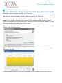
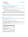
2.3 Once the Microsoft .NET Framework 4 is installed, or skipped if already present, Click
“install” in the following window.
2.4 The “Ozone Adjustable dimmer” software will be automatically launched at the end of the
installation procedure.
A new dedicated desktop icon and Start menu folder will be created for direct SW execution.
North America
Eu and RoW
ROAL Electronics S.p.A
Via Jesina 56/A
60022 – Castelfidardo (AN) - Italy
Tel:+39 071 721461
Fax:+ 39 071 72146 480
www.roallivingenergy.com
ROAL Electronics USA, Inc.
701, Main St. Suite 405
Stroudsburg, PA18360
Phone: + 1 570 421 5750
Fax: +1 570 421 5687
Rev. 00 – 12 May 2011 – Page 4/9
User Manual 1
Ozone Adjustable Dimmer
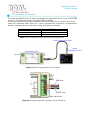
3 USB driver and Ozone Programming Tool installation procedure
3.1 Enter the “usb driver” folder (included in the “Ozone Setup Files.zip”) and launch
“OzoneDriverSetup” file.
3.2 If you have User Account Control enabled (Windows Vista or Windows 7), click “Yes” or
“Continue” in the window that will appear on the screen.
3.3 Wait until the installation procedure ends.
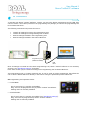
3.4 Connect the Ozone Programming Tool to the USB PC port and follow all the instructions to
complete the driver setup.
4 Software update
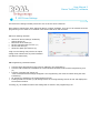
4.1 Uninstall the old SW version.
Go to: StartÆControl PanelÆPrograms and FeaturesÆOzone Adjustable DimmerÆClick
“Uninstall/Change” button.
4.2 Install the new SW version, following the procedure from paragraph 2.
North America
Eu and RoW
ROAL Electronics S.p.A
Via Jesina 56/A
60022 – Castelfidardo (AN) - Italy
Tel:+39 071 721461
Fax:+ 39 071 72146 480
www.roallivingenergy.com
ROAL Electronics USA, Inc.
701, Main St. Suite 405
Stroudsburg, PA18360
Phone: + 1 570 421 5750
Fax: +1 570 421 5687
Rev. 00 – 12 May 2011 – Page 5/9
User Manual 1
Ozone Adjustable Dimmer
5 OZONE Adjustable dimmer SW setting
The “Ozone Adjustable dimmer” PC software has been designed to work in combination with
the “Ozone programming tool” (see AN3_Ozone Setting). A custom night light profile shape
can be created using the computer SW. After that, by a USB connection, it will be stored in the
Ozone programming tool to program the Ozone LED driver memory without using a PC,
directly in the final product field.
Once the custom night light profile shape is stored in the Ozone programming tool, it can be
reloaded by using the PC SW or saved in a dedicate computer folder.
The procedure below will allow you an easy and fast product usage.
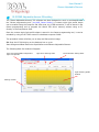
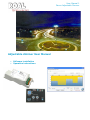
5.1 Start the PC SW clicking on the desktop icon or go to:
StartÆProgramsÆRoal Electronics SpaÆOzone toolsÆOzone Adjustable Dimmer.
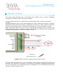
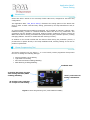
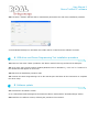
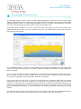
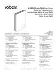
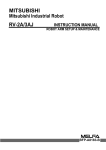
The following Main Sw window will appear:
Up to 5 programmable independent
light-level periods
Light level dimming slider
Period duration setting slider
Light dimming profile
window
Settings section
North America
Eu and RoW
ROAL Electronics S.p.A
Via Jesina 56/A
60022 – Castelfidardo (AN) - Italy
Tel:+39 071 721461
Fax:+ 39 071 72146 480
www.roallivingenergy.com
ROAL Electronics USA, Inc.
701, Main St. Suite 405
Stroudsburg, PA18360
Phone: + 1 570 421 5750
Fax: +1 570 421 5687
Rev. 00 – 12 May 2011 – Page 6/9
User Manual 1
Ozone Adjustable Dimmer
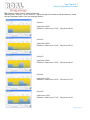
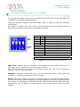
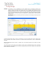
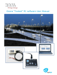
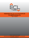
5.2 Creating a new custom night light profile
Starting from “Period 1” up to “Period 5”, adjust all light levels and period durations by using
the two dedicated sliders (see the example below).
Period 1:
Light level=50%
Duration= Start time 15:00 – Stop time 19:00
Period 2:
Light level=90%
Duration= Start time 19:00 – Stop time 24:00
Period 3:
Light level=30%
Duration= Start time 24:00 – Stop time 04:00
Period 4:
Light level=70%
Duration= Start time 04:00 – Stop time 07:00
Period 5:
Light level=10%
Duration= Start time 07:00 – Stop time 10:00
North America
Eu and RoW
ROAL Electronics S.p.A
Via Jesina 56/A
60022 – Castelfidardo (AN) - Italy
Tel:+39 071 721461
Fax:+ 39 071 72146 480
www.roallivingenergy.com
ROAL Electronics USA, Inc.
701, Main St. Suite 405
Stroudsburg, PA18360
Phone: + 1 570 421 5750
Fax: +1 570 421 5687
Rev. 00 – 12 May 2011 – Page 7/9
User Manual 1
Ozone Adjustable Dimmer
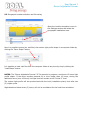
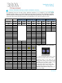
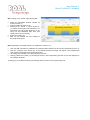
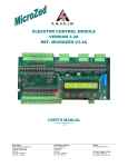
5.3 Geographic location selection and file saving
Open the Location dropdown menu in
the Settings section and select the
geographic installation area.
Now it is possible to save (as .oad files) the custom light profile shape in a computer folder by
clicking the “Save Shape” button.
It is possible to load .oad files from the computer folder at any time by simply clicking the
“Load Shape” button.
NOTES: The “Ozone Adjustable Dimmer” PC Sw permits to program a maximum 19 hours light
profile shape. If the lamp remains powered for a time longer than 19 hours, during the
additional hours (over 19 hours) the light level will remain at the “Period 5” level.
The custom light profile will be synchronized with the local (installation place) time after two
(2) nights cycles.
Night durations below three (3) hours, will not be considered for the local time calculation.
North America
Eu and RoW
ROAL Electronics S.p.A
Via Jesina 56/A
60022 – Castelfidardo (AN) - Italy
Tel:+39 071 721461
Fax:+ 39 071 72146 480
www.roallivingenergy.com
ROAL Electronics USA, Inc.
701, Main St. Suite 405
Stroudsburg, PA18360
Phone: + 1 570 421 5750
Fax: +1 570 421 5687
Rev. 00 – 12 May 2011 – Page 8/9
User Manual 1
Ozone Adjustable Dimmer
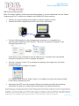
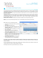
5.4 Programming sequence
Once the custom lighting profile shape has been defined, it can be transferred into the “Ozone
Programming Tool” in order to be loaded in the OZONE LED Driver memory.
•
•
Create your custom lighting profile shape or load an existing .oad file.
Connect the Ozone Programming Tool to the PC by a USB cable.
•
Tick the USB connection in the Programming SW section (1) to establish the
communication between the PC and OPT. The word “connected” will appear in the
Programming section (2).
(1)
(2)
If the device is not connected to the PC USB port or if a problem was encountered
during the connection, an error message will appear.
•
Click the “Program” button (2) to transfer the lighting profile shape into the Ozone
Programming Tool.
A success feedback message will appear.
For a double check click the “Read” button (2) to display the light profile shape loaded
in the Ozone Programming tool.
•
Disconnect the OPT from the computer USB port and follow the AN3_Ozone Setting
instruction to install your custom light profile shape in the Ozone LED driver.
Roal Electronics, S.p.A. may change product specifications and accordingly the information presented in this document. Customers are responsible for their
products and applications using Roal Electronics, S.p.A. products. Roal Electronics, S.p.A. assumes no liability from the use of its products outside of
specifications. No license is granted to any intellectual property rights by this document. ROAL ELECTRONICS, S.P.A. DISCLAIMS ALL
REPRESENTATIONS AND WARRANTIES OF ANY KIND, EXPRESS OR IMPLIED, INCLUDING, BUT NOT LIMITED TO, IMPLIED
WARRANTIES OF NONINFRINGEMENT, MERCHANTABILITY AND FITNESS FOR A PARTICULAR PURPOSE
North America
Eu and RoW
ROAL Electronics USA, Inc.
ROAL Electronics S.p.A
701, Main St. Suite 405
Via Jesina 56/A
Stroudsburg, PA18360
60022 – Castelfidardo (AN) - Italy
www.roallivingenergy.com
Phone: + 1 570 421 5750
Tel:+39 071 721461
Fax: +1 570 421 5687
Fax:+ 39 071 72146 480
Rev. 00 – 12 May 2011 – Page 9/9
KEY PERFORMANCE DATA
OZONE 70W LED DRIVER SERIES
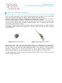
OZONE RSOZ070 SERIES
70W Single Channel
Programmable LED Drivers
ELECTRICAL FEATURES
- Universal Input Range
(120/240/277 Vac)
- High Efficiency, 90% typ
- Active PFC > 0.9
- THD < 20%
- 3,75W +5Vdc Auxiliary Output
- OV, OC, OT and Short Circuit
Protection
- -30°C /+85°C Operating
Case Temperature
- Low Output Ripple Current
DESCRIPTION
- Intelligent Cold Start Function and
Undervoltage dimming Function
Ozone is a 70W programmable LED Driver that combines smart
technology and high flexibility features.
- Long Life Time
- ROHS Compliant
CONTROL FEATURES
- Programmable Constant Current
Output
- Easy to use Program Interfaces
(Ozone Programming Tool and
Ozone Toolset Software)
- 0-10V or 1-10V Standard Dimming
Controls
- LEDs Over Temperature Protection
(by NTC)
- DALI Ready (IEC 62386)
- PWM Ready
- Adjustable Dimmer Function
- Constant Light Function
- Fade Time Setting
SAFETY APPROVALS:
World Wide Safety Approvals
A single channel, constant current LED ballast, Ozone is designed
for directly powering up LEDs in high power indoor and outdoor
lighting fixtures, such as street and tunnel lighting, parking lot and
wide area lighting, as well as in industrial and high bay lighting
applications.
Designed in a super compact 5.82”x2.36”x1.37” package, the
Series includes only four different models that cover applications
from 20V to 195V, with currents from 350mA to 2.6A.
The intelligent core of the driver permits to program the output
current in 50mA steps inside the range of each model, which
makes the Ozone extremely flexible and suitable for different kind
of applications.
By converting energy at 90% typical efficiency, the Ozone Series
makes easier the thermal management in space constrained
systems, offering high reliability in environmentally friend
solutions.
A built in +5V Auxiliary circuit permits to power up active cooling
devices or external logic, while the DALI/PWM interface makes the
driver configurable through the standard control protocols.
With the optional Ozone Programming Tool and the free Ozone
Toolset Software users can implement advanced functions, such as
the Adjustable Dimming and the Constant Light ones, which
eliminate the need for any additional electronics inside the fixture
except the LEDs themselves.
KEY PERFORMANCE DATA
OZONE 70W LED DRIVER SERIES
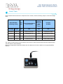
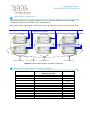
Models Table
Ozone 70W LED Drivers Series in composed of four models, with the following output current and voltage
rates.
Model Number
(Ordering Code)
Pout
max
Output Voltage Range
(Under Regulation)
Absolute
Maximum
Vout
(Under any
condition)
Iout min ;
Iout Max
Package
Dash #
W
Vdc
Vdc
mA
RSOZ070
-200-Full
70
From 120 to 195
200
From 350 to 550
RSOZ070
-120-Full
70
From 60 to 115
120
From 350 to 1100
RSOZ070
-60-Full
70
From 30 to 56
60
From 350 to 2100
RSOZ070
-35-Full
70
From 20 to 33
35
From 1000 to 2600
The output currents and the control features can be set for each model through the Ozone Programming
Tool and Ozone Toolset Software.
Refer to the appropriate Application Notes and User Manuals for further details on the programmability
features.
Eu and RoW
ROAL Electronics S.p.A
North America
ROAL Electronics, USA, Inc.
KEY PERFORMANCE DATA
OZONE 70W LED DRIVER SERIES
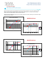
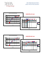
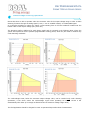
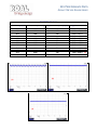
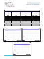
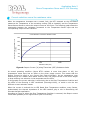
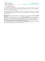
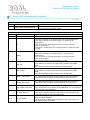
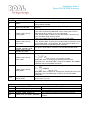
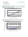
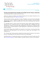
Efficiency and PFC performance
Ozone LED Driver shows very good efficiency and power factor performance even when operating at low
loads. For each model the typical efficiency value is 90%, while the PF is >0.9 from 30% max load at
120Vac, 50% max load at 230Vac, 80% max load at 277Vac.
Following are the characteristic plots for the four Ozone LED driver models, referring to the maximum output
voltage operating condition.
Efficiency / Pout (Max Output Voltage)
RSOZ070-35-Full
91,0%
90,0%
89,0%
PF / Pout (Max Output Voltage)
E fficiency
88,0%
120Vac
1,0
230Vac
87,0%
86,0%
277Vac
0,9
85,0%
84,0%
0,8
83,0%
PF
120Vac
82,0%
0
10
20
30
40
50
60
70
0,7
230Vac
277Vac
80
0,6
Pout (W)
0,5
0,4
0,00
10,00
20,00
30,00
40,00
50,00
60,00
70,00
80,00
Pout (W)
Efficiency / Pout (Max Output Voltage)
RSOZ070-60-Full
92,0%
91,0%
90,0%
PF / Pout (Max Output Voltage)
120Vac
88,0%
230Vac
1,0
87,0%
277Vac
0,9
86,0%
85,0%
0,8
84,0%
120Vac
83,0%
PF
E ffici en cy
89,0%
0
10
20
30
40
Pout (W)
50
60
70
230Vac
0,7
80
277Vac
0,6
0,5
0,4
0
10
20
30
40
50
60
70
80
Pout (W)
Eu and RoW
ROAL Electronics S.p.A
Via Jesina 56/A
North America
ROAL Electronics, USA, Inc.
701, Main St. Suite 405
KEY PERFORMANCE DATA
OZONE 70W LED DRIVER SERIES
Efficiency / Pout (Max Output Voltage)
RSOZ070-120-Full
93,0%
92,0%
91,0%
90,0%
PF / Pout (Max Output Voltage)
E ffici en cy
89,0%
120Vac
88,0%
1,0
230Vac
87,0%
277Vac
86,0%
0,9
85,0%
84,0%
0,8
120Vac
83,0%
PF
82,0%
0
10
20
30
40
50
60
70
230Vac
0,7
277Vac
80
0,6
Pout (W)
f
0,5
0,4
0,00
10,00
20,00
30,00
40,00
50,00
60,00
70,00
80,00
Pout (W)
Efficiency / Pout (Max Output Voltage)
RSOZ070-200-Full
92,0%
91,0%
90,0%
PF / Pout (Max Output Voltage)
88,0%
120Vac
1,0
230Vac
87,0%
277Vac
86,0%
0,9
85,0%
84,0%
0,8
83,0%
120Vac
PF
E ffici en cy
89,0%
82,0%
0
10
20
30
40
50
60
70
80
230Vac
0,7
277Vac
0,6
Pout (W)
0,5
0,4
0
10
20
30
40
50
60
70
80
Pout (W)
Eu and RoW
ROAL Electronics S.p.A
North America
ROAL Electronics, USA, Inc.
KEY PERFORMANCE DATA
OZONE 70W LED DRIVER SERIES
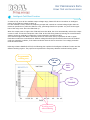
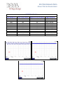
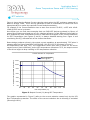
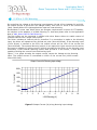
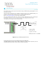
Undervoltage Dimming Operation
Ozone LED driver is able to operate under the minimum value of the output voltage range in order to allow
dimming functions through an analog signal (0-10V, 1-10V or variable resistor) or a DALI/PWM signal.
It is therefore possible to reduce the output current starting from a full load condition located near the
bottom value of the output voltage spec (Vout min).
The dimming profile is different for each Ozone model and it’s reported in the following plots, where the
yellow area represents all the possible programmable working points, while the pink area is reached only
under dimming conditions.
RSOZ070-35
RSOZ070-60
RSOZ070-120
RSOZ070-200
The undervoltage areas, below the minimum output voltage value, can be reached only under dimming
operations; if the driver enters the undervoltage region when operating at nominal current it will
automatically shut down (a 2V margin is allowed under the minimum voltage range value).
The final application should be designed in order to operate always within these characteristics.
Eu and RoW
ROAL Electronics S.p.A
North America
ROAL Electronics, USA, Inc.
KEY PERFORMANCE DATA
OZONE 70W LED DRIVER SERIES
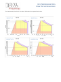
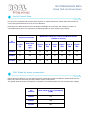
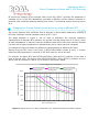
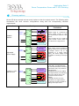
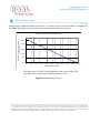
Intelligent Cold Start Function
In order to fully cover all the available output voltage range, Ozone LED driver introduces an intelligent
control of the LED load voltage at start up.
For each settable current, the driver temporary accepts and controls an overload voltage higher than the
maximum specified one (while the LEDs are cold), permitting therefore to operate very close to the upper
limit of the range even when the LEDs heat up.
When the output power is higher than 72W and lower than 80W, the driver automatically reduces the output
current in order to limit the load power under 72W. As the LED string heats up lowering the overall forward
voltage, the driver gradually increases the current toward the nominal set value.
If an overload higher than 80W is detected, the driver shuts down until it is powered off and on again.
Each Ozone model has nevertheless an absolute voltage threshold (OV Threshold) that cannot be violated
under any operative condition; if the load exceeds this limit the driver enters the over voltage protection
mode and shuts down.
Referring to Ozone RSOZ070-35-Full, the following plot explains the Intelligent Cold Start Function and the
different working regions. The purple area represents the temporary admitted overload working points.
Programmable
working area
70W rate
limit
80W
limit
RSOZ070-35
OV
Threshold
Working areas
when dimming
Eu and RoW
ROAL Electronics S.p.A
North America
ROAL Electronics, USA, Inc.
KEY PERFORMANCE DATA
OZONE 70W LED DRIVER SERIES
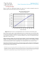
The characteristic plots for the four Ozone 70W models are reported here below.
RSOZ070-35
RSOZ070-60
RSOZ070-120
RSOZ070-200
Eu and RoW
ROAL Electronics S.p.A
North America
ROAL Electronics, USA, Inc.
KEY PERFORMANCE DATA
OZONE 70W LED DRIVER SERIES
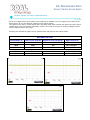
Output Ripple Current Characteristics
The driver’s digital control of the output current permits to maintain a very low ripple current value on the
LED string for all over the different voltage/current working points.
The ripple current value is usually higher when operating at full power towards the upper limit of the output
voltage range, while it decreases significantly (under 10% of the set current) for working voltages located
near the bottom value of the range.
Following are reported the ripple current measurements and plots for each Ozone model.
RSOZ070-35-Full
Load Voltage (V)
Load Current (mArms)
Ripple Current (mA pk-pk)
Ripple Current %
32.86
28.54
20.20
2096
2093
2092
228
163
149
10,9% = ± 5,45%
7,8% = ± 3,90%
7,1% = ± 3,55%
(1)
26.77
20.14
2581
2583
178
165
6,9% = ± 3,45%
6,4% = ± 3,20%
(3)
(2)
(2)
(1)
(3)
Eu and RoW
ROAL Electronics S.p.A
Via Jesina 56/A
North America
ROAL Electronics, USA, Inc.
701, Main St. Suite 405
KEY PERFORMANCE DATA
OZONE 70W LED DRIVER SERIES
RSOZ070-60-Full
Load Voltage (V)
Load Current (mArms)
Ripple Current (mA pk-pk)
Ripple Current %
56,0
54,9
52,8
49,8
44,6
40,3
37,3
33,9
30,6
1247
1246
1247
1249
1248
1247
1247
1245
1244
141
122
102
83
77
77
70
70
70
11,3% = ± 5,65%
9,8% = ± 4,9%
8,2% = ± 4,1%
6,6% = ± 3,3%
6,2% = ± 3,1%
6,2% = ± 3,1%
5,6% = ± 2,8%
5,6% = ± 2,8%
5,6% = ± 2,8%
(1)
33,3
30,2
2104
2097
160
144
7,6% = ± 3,8%
6,9% = ± 3,45%
(3)
(2)
(2)
(1)
(3)
Eu and RoW
ROAL Electronics S.p.A
Via Jesina 56/A
North America
ROAL Electronics, USA, Inc.
701, Main St. Suite 405
KEY PERFORMANCE DATA
OZONE 70W LED DRIVER SERIES
RSOZ070-120-Full
Load Voltage (V)
Load Current (mArms)
Ripple Current (mA pk-pk)
Ripple Current %
114.8
111.5
108.3
101.6
91.7
80.1
72.8
64.4
60.0
603
604
606
606
607
608
608
610
610
83
58
48
45
42
38
35
35
35
13,8% = ± 6,90%
9,6% = ± 4,80%
7,9% = ± 3,95%
7,4% = ± 3,70%
6,9% = ± 3,45%
6,2% = ± 3,10%
5,7% = ± 2,85%
5,7% = ± 2,85%
5,7% = ± 2,85%
(1)
63.6
59.9
1091
1094
64
64
5,9% = ± 2,95%
5,9% = ± 2,95%
(3)
(2)
(2)
(1)
(3)
Eu and RoW
ROAL Electronics S.p.A
Via Jesina 56/A
North America
ROAL Electronics, USA, Inc.
701, Main St. Suite 405
KEY PERFORMANCE DATA
OZONE 70W LED DRIVER SERIES
RSOZ070-200-Full
Load Voltage (V)
Load Current (mArms)
Ripple Current (mA pk-pk)
Ripple Current %
194.9
191.5
182.1
169.8
148.5
134.0
124.6
120.1
352
346
345
344
346
346
348
349
92
60
42
38
36
36
35
33
26,1% = ± 13,05%
17,3% = ± 8,65%
12,2% = ± 6,10%
11,0% = ± 5,50%
10,4% = ± 5,20%
10,4% = ± 5,20%
10,0% = ± 5,00%
9,5% = ± 4,75%
(1)
127.2
119.9
542
537
35
32
6,5% = ± 3,25%
6,0% = ± 3,00%
(3)
(2)
(2)
(1)
(3)
Eu and RoW
ROAL Electronics S.p.A
Via Jesina 56/A
North America
ROAL Electronics, USA, Inc.
701, Main St. Suite 405
KEY PERFORMANCE DATA
OZONE 70W LED DRIVER SERIES
Inrush Current Data
Due to its very limited Inrush Current peak at power on, Ozone LED driver makes easier the selection of
overcurrent protection devices such as circuit breakers.
Referring to the different kinds of Circuit Breakers available on the market, the maximum number of
connectable Ozone drivers is reported in the following table for each nominal input voltage.
Inrush Current Data
Vin
nominal
Maximum Loading for each Circuit Breaker Series
(number of drivers)
I peak
(A)
Half Value
Time
(s)
Type B
10A
Type B
16A
Type C
10A
Type C
16A
Type D
10A
Type D
16A
120Vac
11
250
25
40
41
66
83
133
230Vac
21
246
13
20
21
34
43
69
277Vac
26,8
250
10
16
16
27
33
54
DALI Stand-by power consumption
Ozone LED driver offers a very low stand-by power consumption when the LEDs are switched off from the
DALI port (DALI off command) and the auxiliary output is not loaded.
The typical stand-by power consumption is reported in the following table for each nominal input voltage.
Eu and RoW
ROAL Electronics S.p.A
Vin
nominal
DALI Stand-by typ. consumption
(mW)
120Vac
279
230Vac
408
277Vac
502
North America
ROAL Electronics, USA, Inc.
Application Note 1
Ozone Wiring Diagram
Introduction
Ozone LED Driver is an Intelligent and flexible device, designed for indoor and outdoor lighting
applications.
This Application Note “AN1 Ozone Wiring Diagram” provides technical information for the
wiring connections of the Ozone LED Driver and mechanical fixing (all models).
Ozone LED Driver has a wide voltage range input connector and a multifunction output
connector for LED connections, LED thermal protection (NTC), dimming and +5Vaux.
It has also an additional connector for DALI communication.
This document describes how to connect the Ozone LED Driver (AC Input, Constant Current
output Channel, Communication and Controls).
Connectors Overview
Figure 1: Input AC connector
Figure 2: LEDs, NTC, 0-10V / 1-10V
Dimming, Vaux and DALI connectors
Application Note 1
Ozone Wiring Diagram
AC Input Connection
Ozone LED Driver can be powered by a wide voltage range AC Input from 120 to 277Vac
(Figure 4).
Consult the product DataSheet “DS1_Ozone LED Driver 70W” for Input Voltages and
Current ratings.
AWG 22-16
Wire stripping 10mm
120/230/277Vac
{
Figure 4: AC input Connector
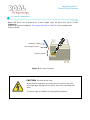
CAUTION: Electrical shock risks.
Wrong device installation can cause serious injuries to the user,
and irreparable damages to the device and to the connected LED
lamp.
The driver may be installed only by qualified operators.
Eu and RoW
ROAL Electronics S.p.A
Via Jesina 56/A
60022 – Castelfidardo (AN) - Italy
Tel:+39 071 721461
Fax:+ 39 071 72146 480
North America
www.roallivingenergy.com
ROAL Electronics USA, Inc.
701, Main St. Suite 405
Stroudsburg, PA18360
Phone: + 1 570 421 5750
Fax: +1 570 421 5687
Rev. 03 - 04 Oct 2012 – Page 2/6
Application Note 1
Ozone Wiring Diagram
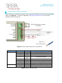
Output and Driving Connection
Ozone LED Driver versatility permits the user to approach different driving solutions as showed
below (see Figure 5). Consult the DataSheet “DS1_Ozone LED Driver 70W” for Output
Voltages and Current ratings.
DALI/PWM
DALI/PWM
+5V Aux
RTN
Ts
RTN
0-10V Dimm
RTN
-LED
+LED
AWG 26-16
Wire stripping 10mm
Figure 5: Ozone Output and Control Connections
Connector
8 pins connector
Pin number
1
2
3
4
2 pins connector
5
6
7
8
1
2
Pin name
+LED
-LED
RTN
0-10V
DIMM
RTN
Ts
RTN
+5Vaux
DALI/PWM
DALI/PWM
Description
LEDs positive output
LEDs negative output
Return
1/10V dimming input
Return
Thermal sense input
Return
Auxiliary +5V
DALI input or PWM dimming input
DALI input or PWM dimming input
Table 1: Ozone Connections Table
Eu and RoW
ROAL Electronics S.p.A
Via Jesina 56/A
60022 – Castelfidardo (AN) - Italy
Tel:+39 071 721461
Fax:+ 39 071 72146 480
North America
www.roallivingenergy.com
ROAL Electronics USA, Inc.
701, Main St. Suite 405
Stroudsburg, PA18360
Phone: + 1 570 421 5750
Fax: +1 570 421 5687
Rev. 03 - 04 Oct 2012 – Page 3/6
Application Note 1
Ozone Wiring Diagram
Output/Control
+LED, -LED
0-10V Dimm
Ts
(Thermal sense)
+5V Aux
DALI
PWM dimming
Short Description
Use these connector pins (1-2) to connect the LED string.
Pay attention to respect the LED Driver output ratings.
For additional info see the Product DataSheet “DS1_Ozone LED Driver
70W”.
An external 0-10V standard dimmer can be connected to dim the LED
driver output current, from 10% to 100% of the maximum current set .
For additional info see “AN2_Ozone Temperature Sense& 0-10V dimming”.
Using output connector pins (5-6), to connect a negative coefficient
thermistor (NTC), in order to avoid a potential extra temperature of the
LED fixture. For additional info see “AN2_Ozone Temperature Sense& 010V dimming”.
Using output connector pins (7-8), the user has the possibility to power
an external active cooling device or any max 3.75W external control
circuitry.
Ozone LED driver can be connected to a DALI network using the dedicated
2-way connector, both for input and output transmissions without polarity.
The same connector may be used for PWM dimming.
For additional information see “AN4_Ozone DALI&PWM Dimming” .
Ozone can accept a PWM dimming signal on the DALI input connector
according to the EN60929 annex E3. For additional info see “AN4_Ozone
DALI&PWM Dimming”.
Table 2: Ozone Output and Controls
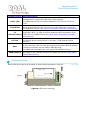
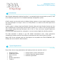
Mechanical Fixing
Ozone LED Driver has to be mounted on a flat surface as shown in Figure 6.
Figure 6: LED Driver mounting
Eu and RoW
ROAL Electronics S.p.A
Via Jesina 56/A
60022 – Castelfidardo (AN) - Italy
Tel:+39 071 721461
Fax:+ 39 071 72146 480
North America
www.roallivingenergy.com
ROAL Electronics USA, Inc.
701, Main St. Suite 405
Stroudsburg, PA18360
Phone: + 1 570 421 5750
Fax: +1 570 421 5687
Rev. 03 - 04 Oct 2012 – Page 4/6
Application Note 1
Ozone Wiring Diagram
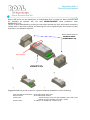
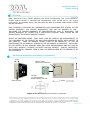
Ozone Remote Gear Kit
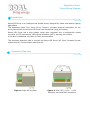
Ozone LED driver can be installed as an Independent Unit by using the Ozone Remote Gear
Kit, available as optional with the code RSOZ070-RGKIT (Roal production code:
RHMB346007-00).
The kit is easily assembled by pushing the two shells toward the input and output connectors,
locking them in the case housings and securing the unit by tightening the two screws in place,
as shown in the following pictures:
Ozone Remote Gear Kit
RSOZ070-RGKIT
(RHMB346007-00)
Case hausings
Ozone LED Driver
RSOZ070-xx-Full
Suggested AWG wires and screws for a good mechanical installation are the following:
Input and Output connectors: wires AWG 18/20 Style 1007
Dali connector:
wires AWG 22/24 UL1672
Screw type:
Thread forming screw for thermoplastic, Pan head screw,
Phillips H cross recessed, d:3.5mm L:12mm
Screw torque:
10-12Kgf x cm, Phillips H2 screwdriver tip
Eu and RoW
ROAL Electronics S.p.A
Via Jesina 56/A
60022 – Castelfidardo (AN) - Italy
Tel:+39 071 721461
Fax:+ 39 071 72146 480
North America
www.roallivingenergy.com
ROAL Electronics USA, Inc.
701, Main St. Suite 405
Stroudsburg, PA18360
Phone: + 1 570 421 5750
Fax: +1 570 421 5687
Rev. 03 - 04 Oct 2012 – Page 5/6
Application Note 1
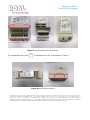
Ozone Wiring Diagram
Case hausings
Figure 7: Ozone Remote Gear Kit installation
The Independent Unit mark
is indicated on the kit, as illustrated in Figure 8.
Figure 8: Ozone Remote Gear Kit
Roal Electronics, S.p.A. may change product specifications and accordingly the information presented in this document. Customers are responsible for their
products and applications using Roal Electronics, S.p.A. products. Roal Electronics, S.p.A. assumes no liability from the use of its products outside of
specifications. No license is granted to any intellectual property rights by this document. ROAL ELECTRONICS, S.P.A. DISCLAIMS ALL
REPRESENTATIONS AND WARRANTIES OF ANY KIND, EXPRESS OR IMPLIED, INCLUDING, BUT NOT LIMITED TO, IMPLIED
WARRANTIES OF NONINFRINGEMENT, MERCHANTABILITY AND FITNESS FOR A PARTICULAR PURPOSE
Eu and RoW
ROAL Electronics S.p.A
Via Jesina 56/A
60022 – Castelfidardo (AN) - Italy
Tel:+39 071 721461
Fax:+ 39 071 72146 480
North America
www.roallivingenergy.com
ROAL Electronics USA, Inc.
701, Main St. Suite 405
Stroudsburg, PA18360
Phone: + 1 570 421 5750
Fax: +1 570 421 5687
Rev. 03 - 04 Oct 2012 – Page 6/6
Application Note 2
Ozone Temperature Sense and 0-10V Dimming
Introduction
Ozone LED Driver is a digital and intelligent Single Channel LED Driver designed for White LED
Applications.
This Application Note “AN2_Ozone Temperature Sense & 01-10V Dimming” provides technical
information to realize an efficient and cost effective Over Temperature Protection of the LEDs
driven by Ozone, and to dim linearly the output current with a 0-10V or 1-10V external
dimming signal. If you are interested in the PWM Dimming in that case please refer to the
Application Note 4 “AN4_Ozone DALI & PWM Dimming”.
Ozone includes a dedicated input (Ts) to realize LEDs Over Temperature protection.
Basically it consists in adopting a Negative Temperature Coefficient sensor (NTC) to detect the
PCB Temperature near the LED solder joint, reducing the output current when a critical high
temperature is reached.
The Thermal protection described in this Application Note is simple and fast to implement;
nevertheless if this protection is not possible or not necessary to be adopted, consider that the
Ozone Thermal sense input pin (Ts) can be leaved unconnected; therefore if no connection is
made, the Driver operates at the nominal output current set point and the LED’s temperature
does not influence the output current value.
This document contains also all the information necessary to dim LEDs by using a 0-10V or 110V signal that comes from a standard dimmer or external control circuitry or sensors.
Ozone dimming characteristics have been tailored to meet the requirements of IEC 60929
Annex E.
Application Note 2
Ozone Temperature Sense and 0-10V Dimming
Thermistor Connecting
This section shows different type of Thermistors and explains how to connect a Negative
Temperature Coefficient (NTC) Thermistor to Ozone.
A single Channel LED Driver is typically used to power White LEDs, usually all connected
in series.
The final application can be a LED Lamp dedicated to Indoor (Wide Area Lighting) or Outdoor
Application (Urban and Street Lighting). Regardless the final use in many cases it is important
to protect LEDs against an Over Temperature that might occur due to abnormal condition.
When using Ozone LED Driver, the use of an appropriate Thermistor (NTC) to monitor the
PCB’s temperature allows to realize an efficient and cost effective LED Board Over Temperature
Protection; the thermistor connection is shown in Figure 1.
DALI/PWM
DALI/PWM
+5V Aux
RTN
Ts
RTN
0-10V Dimm
RTN
-LED
+LED
AWG 26-16
Wire stripping 10mm
Figure 1: NTC Connection (output connector pins 5 and 6)
In some cases the monitoring of the temperature of the PCB or heatsink where LEDs are
mounted is not possible or not required. In this case the dedicated Temperature Sense Input
(Ts) can be left open (not connected) and the Temperature of the LED Board’s PCB will not
influence the Ozone output current.
Eu and RoW
ROAL Electronics S.p.A
Via Jesina 56/A
60022 – Castelfidardo (AN) - Italy
Tel:+39 071 721461
Fax:+ 39 071 72146 480
North America
www.roallivingenergy.com
ROAL Electronics USA, Inc.
701, Main St. Suite 405
Stroudsburg, PA18360
Phone: + 1 570 421 5750
Fax: +1 570 421 5687
Rev. 00 – 30 Mar. 2011 – Page 2/10
Application Note 2
Ozone Temperature Sense and 0-10V Dimming
SMD e non-SMD NTC Thermistors
There are many thermistors with various technologies/case size available in the market and
produced by several manufacturers (Epcos, Vishay, Murata, AVX and others).
Thanks to Ozone design a Negative Temperature Coefficient (NTC) thermistor can be used to
reduce the output current in case of LED Board Over Temperature Condition.
The most common NTCs used in LED Lighting are SMD devices (see Figure 2). This kind of NTC
can be quickly mounted during the SMD assembling phase and it is available with different
sizes (0805, 1206, 0603 and others).
Of course if LEDs are placed into the LED Board through the SMD process (e.g. LEDs produced
by Lumileds, CREE, Osram, Seoul, Nichia etc.), then the right choice for the NTC is a SMD
Thermal Sensor.
Figure 2: SMD NTC thermistor
Figure 3: Ring lug NTC thermistor
Nevertheless some LEDs (e.g. Multichip LEDs) produced by Manufactures like Bridgelux,
Citizen, Xicato etc. , are designed to be mounted directly on the heatsink fixing them by the
use of screws. In this case the SMD assembling phase is not present in the LED Board
production process and a LUG NTC (see Figure 3) can be easily adopted because it is
assembled as a probe, in order to be assembled on the LED’s heatsink by using a screw.
For best performance, the NTC sensing thermistor should be located close to LEDs or in the hot
spot of the LED Board, if any.
Eu and RoW
ROAL Electronics S.p.A
Via Jesina 56/A
60022 – Castelfidardo (AN) - Italy
Tel:+39 071 721461
Fax:+ 39 071 72146 480
North America
www.roallivingenergy.com
ROAL Electronics USA, Inc.
701, Main St. Suite 405
Stroudsburg, PA18360
Phone: + 1 570 421 5750
Fax: +1 570 421 5687
Rev. 00 – 30 Mar. 2011 – Page 3/10
Application Note 2
Ozone Temperature Sense and 0-10V Dimming
Current reduction versus the resistance value
When the temperature increases over a certain limit, the NTC mounted on the LED Board
measures the Temperature of the mounting surface (PCB or heatsink) and the Temperature
Sense feature allows to reduce the output current of the Driver. The following graph shows the
relationship between the resistance connected to the Temperature Sense input and the
corresponding output current reduction.
Current Reduction Vs Thermistor Resistance Value
% Output Current (normalized to set
current)
120%
100%
80%
60%
40%
20%
0%
0
10000
20000
Resistance Value (ohm)
Figure 4: Output Current (%) along Thermistor (NTC) Resistance Value
At normal operating condition (where NTC’s resistor is more than about 11 kΩ), the
temperature sense input has no effect on the driver output current. This means that the
Output Current is equal to the Current Set (Iout=100%Iset). As the temperature rises
determining a NTC resistor value below 10kΩ-10.5kΩ, the output current of the driver begins
to drop resulting in a reduction in the temperature at the LEDs.
In this graphic the current reduction is exclusively due to the Over Temperature Condition and
the effect of the Dimming is NOT considered (Dimming=100%), to avoid to mix the two
different current reduction causes.
When the current is reduced due to LED Board Over Temperature condition, many factors,
predominately the thermal impedance of the LED heatsink, play a role in determining the
ultimate thermal equalization.
According to Figure 4, when the Over Temperature Condition is removed, the Output current
comes back gradually to its original Value (Iout=100% Iset).
Eu and RoW
ROAL Electronics S.p.A
Via Jesina 56/A
60022 – Castelfidardo (AN) - Italy
Tel:+39 071 721461
Fax:+ 39 071 72146 480
North America
www.roallivingenergy.com
ROAL Electronics USA, Inc.
701, Main St. Suite 405
Stroudsburg, PA18360
Phone: + 1 570 421 5750
Fax: +1 570 421 5687
Rev. 00 – 30 Mar. 2011 – Page 4/10
Application Note 2
Ozone Temperature Sense and 0-10V Dimming
NTC selection
Figure 4 shows that the Output Current reduction starts when the NTC resistance measured by
Ozone is around 10kΩ. This is the key parameter to take in consideration to choose the more
appropriate NTC to realize the required Current Reduction behavior.
For example if the Current Reduction has to start from around 75-80°C, a NTC with 10kΩ12kΩ @ 80°C has to be chosen.
Here below you can find some examples that use SMD NTC devices produced by Epcos; of
course Epcos Codes mentioned are only for a design reference. In fact different Epcos codes or
NTC produced by other manufacturers can be used and the diagram of the Current Reduction
Vs NTC Temperature (see Figures 5 and 6) is always obtained starting form Figure 4 and
considering the R(T) characteristic of the chosen thermistor.
Ozone design produces a knee in the output current regulation at approximately 75°C when it
operates with the Epcos Code B57471V2104J062 (100 kΩ @ 25°C) as shown in Figure 5.
At temperatures less than 75°C, the temperature sense input has no effect on the driver
output current (Iout=100%Iset); as the NTC temperature rises above 75°C, the output current
of the driver begins to drop resulting in LED temperature reduction.
Current reduction Vs Temperature
% Output Current (normalized to set current)
B57471V2104J062
100 kΩ @ 25°C
120%
100%
80%
60%
40%
20%
0%
25
35
45
55
65
75
85
95
105
115
125
NTC Temperature (°C)
Figure 5: Output Current (%) along NTC Temperature
The graphic represented in Figure 5 refers to the current reduction caused only by the LED
Over Temperature protection. The effect of the current reduction due to dimming is excluded
(Dimming=100%).
Eu and RoW
ROAL Electronics S.p.A
Via Jesina 56/A
60022 – Castelfidardo (AN) - Italy
Tel:+39 071 721461
Fax:+ 39 071 72146 480
North America
www.roallivingenergy.com
ROAL Electronics USA, Inc.
701, Main St. Suite 405
Stroudsburg, PA18360
Phone: + 1 570 421 5750
Fax: +1 570 421 5687
Rev. 00 – 30 Mar. 2011 – Page 5/10
Application Note 2
Ozone Temperature Sense and 0-10V Dimming
Of course the changing of the nominal value of the NTC @25°C (typically this parameter is
indicated as R25 in the NTC datasheets) generates a different current reduction behavior in
particular with a different derating starting point (knee). The following section clears up how to
do it.
Changing the Current Reduction behaviour by using a different NTC
If a current reduction with a different knee is required, it can be easily obtained by choosing a
NTC with a different nominal resistance value @ 25° C (R25).
The graph depicted in Figure 4 can be used to determine the required resistance
characteristics of alternate NTC resistors; the general rule that comes from it is that if a knee
at lower temperature is required, then the resistance value @25°C has to be reduced, whereas
if a knee with a higher temperature is admitted then the R25 value has to be increased.
For example the Figure 6 shows the different curves depending on different NTC used.
Starting from the NTC used in the Figure 5 (B57471V2104J062 (100kΩ @ 25°C), if a lower
maximum PCB temperature is required, a NTC with lower R25 has to be used.
For example, the Epcos NTC code B57471V2473J062 (47kΩ @25°C) produces a curve with a
knee at around 55°C; the device code B57471V2333J062 (33 kΩ @25°C) produces a curve
with a knee at around 45°C and so on, as shown in the Figure 6 below.
Current reduction Vs Temperature
B57471V2104J062
100 kΩ @ 25°C
B57471V2473J062
47 kΩ @ 25°C
B57471V2333J062
33 kΩ @ 25°C
%Output Current (normalized to set current)
120%
100%
80%
60%
40%
20%
0%
25
35
45
55
65
75
85
95
105
115
125
NTC Temperature (°C)
Figure 6: Output Current (%) along Temperature, by using different NTC Thermistors (Epcos)
Eu and RoW
ROAL Electronics S.p.A
Via Jesina 56/A
60022 – Castelfidardo (AN) - Italy
Tel:+39 071 721461
Fax:+ 39 071 72146 480
North America
www.roallivingenergy.com
ROAL Electronics USA, Inc.
701, Main St. Suite 405
Stroudsburg, PA18360
Phone: + 1 570 421 5750
Fax: +1 570 421 5687
Rev. 00 – 30 Mar. 2011 – Page 6/10
Application Note 2
Ozone Temperature Sense and 0-10V Dimming
Generally moving from one code to another to change the R25 value, the size case of the NTC
can remain the same (in this case a 0805 size has been selected), so that the LED Board
layout is not required to be modified.
The graphics showed in the Figure 6 refer to the current reduction caused only by the LED
Over Temperature protection. The effect of the current reduction due to dimming is excluded
(Dimming=100%).
All the examples mentioned above use Surface-mount NTC thermistors (Epcos, Series
B574**V2).
Alternatively, Epcos offers a similar thermistors (Series B57703M), specifically designed for
Surface temperature measurement, e.g. on housings and heat sinks, with a probe assembly
(see Figure 3), useful to measure the temperature close to LEDs in non-SMD applications.
The method explained above that allows to obtain the Current Reduction Vs NTC Temperature
diagram (see Figures 5 and 6) is valid regardless of the NTC used.
In the non-SMD applications also the NTCs Series NTCALUG, produced by Vishay are
designed to be fixed directly to the LED Board heatsink.
Eu and RoW
ROAL Electronics S.p.A
Via Jesina 56/A
60022 – Castelfidardo (AN) - Italy
Tel:+39 071 721461
Fax:+ 39 071 72146 480
North America
www.roallivingenergy.com
ROAL Electronics USA, Inc.
701, Main St. Suite 405
Stroudsburg, PA18360
Phone: + 1 570 421 5750
Fax: +1 570 421 5687
Rev. 00 – 30 Mar. 2011 – Page 7/10
Application Note 2
Ozone Temperature Sense and 0-10V Dimming
0-10V or 1-10V dimming
By controlling the voltage at the dimming input between 1V and 10V or between 0V and 10V,
the output current of the driver will change linearly from 10% to 100% of the current set
(Iset). Usually White LED Light applications require a linear dimming.
Nevertheless in some case where there are stringent requirements in terms of CCT stability,
the solution is the adoption of a PWM Dimming. In that case please refer to the Application
Note 4 “AN4_Ozone DALI & PWM Dimming”.
The Dim inputs can be connected in parallel with other Ozone drivers to enable control of
multiple fixtures from a single control point.
The driver includes an internal pull-up; therefore if no connection is made to the dimming
input, the driver will operate at the nominal set point (Iout=100%Iset). If the dimming input
(0-10V Dimm) is shorted to the RTN, the output current will be 10% of the current set
(Iout=10%Iset). The external dimming control is not required to inject current into the driver
but must be capable of sinking current (100uA) provided by the driver at the dimming input
connection. If the external dimming control does provide a 0-10V source, it must also be
capable of sinking the current from the dimming input.
Figure 7 is a graph showing the output current versus the Voltage at the dimming
input. The output current is normalized to 100% of the current set (100% means
Iout=100% Iset).
Output Current Vs Dimming input voltage
% I nominal
100%
80%
60%
40%
20%
0%
0
1
2
3
4
5
6
7
8
9
10
1-10V Dimming (V)
Figure 7: Output Current (%) along dimming input voltage
Eu and RoW
ROAL Electronics S.p.A
Via Jesina 56/A
60022 – Castelfidardo (AN) - Italy
Tel:+39 071 721461
Fax:+ 39 071 72146 480
North America
www.roallivingenergy.com
ROAL Electronics USA, Inc.
701, Main St. Suite 405
Stroudsburg, PA18360
Phone: + 1 570 421 5750
Fax: +1 570 421 5687
Rev. 00 – 30 Mar. 2011 – Page 8/10
Application Note 2
Ozone Temperature Sense and 0-10V Dimming
Dimming options
Ozone LED driver accepts various control options to dim the output current. The following table
summarizes the most common configurations along with the corresponding electrical
requirements.
Interface
Circuitry
Digital Input
(optional)
Variable
Resistor
~
Digital Input
(optional)
Adjustable
Power Supply
L
N
Ts
~
+5V Aux
RTN
0-10 V Dim
RTN
DALI
DALI
+ LED
Digital Input
(optional)
L
N
Ts
~
+5V Aux
RTN
0-10 V Dim
RTN
DALI
DALI
+ LED
L
N
NTC
Active Cooling or
External Logic
Adjustable
power supply
LED
NTC
RTN
- LED
OZONE
AC
LED
RTN
- LED
OZONE
AC
0-10V or 1-10V
Wall Dimmer
0-10 V Dim
RTN
DALI
DALI
+ LED
OZONE
AC
Requirements /
Limitations
Ts
0-10V 1-10V
Wall Dimmer
LED
NTC
Active Cooling or
External Logic
Eu and RoW
ROAL Electronics S.p.A
Via Jesina 56/A
60022 – Castelfidardo (AN) - Italy
Tel:+39 071 721461
Fax:+ 39 071 72146 480
Power supply must be capable of
sinking 100uA from each driver.
If multiple drivers are to be
connected to a single power
supply, the Power Supply must
be capable of sinking 100uA per
driver.
Active Cooling or
External Logic
RTN
- LED
+5V Aux
RTN
Resistor range of <10Kohms to
reduce output current to 10%
and >90K ohms to achieve 100%
current.
Refer to Figure 8 for a graph of
output current versus value of
the resistor for a single driver.
0-10V and 1-10V dimmers are
not well characterized. Therefore,
performance may vary between
manufacturers.
As additional drivers are added
to a single dimmer, the dimming
value may change due to the
increased current into the
dimmer.
If multiple drivers are to be
connected to a single Dimmer,
the Dimmer must be capable of
sinking 100uA per driver.
North America
www.roallivingenergy.com
ROAL Electronics USA, Inc.
701, Main St. Suite 405
Stroudsburg, PA18360
Phone: + 1 570 421 5750
Fax: +1 570 421 5687
Rev. 00 – 30 Mar. 2011 – Page 9/10
Application Note 2
Ozone Temperature Sense and 0-10V Dimming
Figure 8 shows the relationship between the value of the resistor connected across the
dimming input versus the output current of a single driver.
Ozone Driver Dimming Control
% Output Current (normalized to set current)
Dimming with a variable resistor
110%
100%
90%
80%
70%
60%
50%
40%
30%
20%
10%
0%
0
10
20
30
40
50
60
70
80
90
100
Resitor value KOhm
Figure 8: Output Current (%) along Resistance value connected to the dimming input.
When using a power supply, control equipment/circuitry or similar device, care must be taken
to ensure the equipment is isolated from the AC power source. If the dimming connections are
to be wired as a Class II circuit, all connected equipment must have the appropriate safety
approvals for Class II circuits.
When connecting multiple drivers to a single control device, it must be appropriately rated and
capable of sinking 100uA of current from each connected driver. As the number of drivers
increase, the dimming performance characteristics may change due to the increased current
into the dimming control circuitry (depending on the characteristics of the external circuit).
The length of the dimming circuit wiring, wire size and the number of drivers connected to the
dimming control must be designed so that the total voltage drop is less then 0.2-0.3V between
the drivers and the dimming control.
Roal Electronics, S.p.A. may change product specifications and accordingly the information presented in this document. Customers are responsible for
their products and applications using Roal Electronics, S.p.A. products. Roal Electronics, S.p.A. assumes no liability from the use of its products outside
of specifications. No license is granted to any intellectual property rights by this document. ROAL ELECTRONICS, S.P.A. DISCLAIMS ALL
REPRESENTATIONS AND WARRANTIES OF ANY KIND, EXPRESS OR IMPLIED, INCLUDING, BUT NOT LIMITED TO, IMPLIED
WARRANTIES OF NONINFRINGEMENT, MERCHANTABILITY AND FITNESS FOR A PARTICULAR PURPOSE.
Eu and RoW
ROAL Electronics S.p.A
Via Jesina 56/A
60022 – Castelfidardo (AN) - Italy
Tel:+39 071 721461
Fax:+ 39 071 72146 480
North America
www.roallivingenergy.com
ROAL Electronics USA, Inc.
701, Main St. Suite 405
Stroudsburg, PA18360
Phone: + 1 570 421 5750
Fax: +1 570 421 5687
Rev. 00 – 30 Mar. 2011 – Page
Application Note 3
Ozone Setting
Introduction
Ozone LED Driver stands for an extremely flexible LED Driver, Designed for fast and easy
configuration.
This Application Note “AN3_Ozone Setting” illustrates the setting options of the Ozone LED
driver in order to allow a fast and easy setting, performed by the lamp manufacturer and /or
installer.
An external dedicated and portable programming tool (available as optional, ordering code:
RSOZ070-PTOOL), permits to customize different Ozone LED driver key parameters. This
guarantees extreme flexibility during final products (lamps) production process, because all
OEMs will be able to directly personalize their products during the production process, avoiding
managing different LED driver models and their stocking inventory.
In addition to the several benefits that this feature allows during the production process, it
permits also to operate directly in the lamp installation field, avoiding wasting of time due to
product’s replacement.
Ozone Programming Tool
The battery powered unit (see Figure 1), is a user friendly remote programmer that permits
the user to manage the following settings:
Output Constant Current Setting
Light Fade Time Setting
DALI communication enabling/disabling.
PWM dimming enabling/disabling.
Feedback LEDs
4-position Dip Switch for Fade
Time setting and DALI/PWM
enabling/disabling.
10-position rotary switches
for Output Current Setting.
Figure 1: Ozone Programming Tool (Code RSOZ070-PTOOL)
“Save” push button for
setting confirmation.
Application Note 3
Ozone Setting
Programming Connections
The Ozone programming tool is easily connectable with Ozone LED driver by the 3-wire cable
(Figure 2). The cable is included in the Code RSOZ070-PTOOL)
The three programming wires are selectable by coloured collars near the metal end terminal.
Follow the connection table below for a correct programming connections correspondence,
between programming wires and Ozone output connector pins involved.
Programming Wire
RED collar wire
BLACK wire
WHITE collar wire
Ozone OUTPUT connector pin
Ts
RTN
0-10V Dimm
Table 1: Ext. programming tool connections correspondence
3-wire Programming cable
Ozone
Programming Tool
Ozone LED driver
AC Line
Figure 2: Ozone Programming Tool connection
RED collar
WHITE collar
Metal end terminal
Figure 3: Programming wires connection to the LED Driver
North America
Eu and RoW
ROAL Electronics S.p.A
Via Jesina 56/A
60022 – Castelfidardo (AN) - Italy
Tel:+39 071 721461
www.roallivingenergy.com
ROAL Electronics USA, Inc.
701, Main St. Suite 405
Stroudsburg, PA18360
Phone: + 1 570 421 5750
Fax: +1 570 421 5687
Rev. 04 – 20 Jun 2012 – Page 2/7
Application Note 3
Ozone Setting
Dip-switch settings (Fading, DALI, Dimming)
The 4-position dip-switch on the remote programming tool permits to set the light fade time
in addition to DALI/PWM enabling/disabling.
Follow the dip-switch settings combination table (Table 2) below to select the requested
configuration.
Each switch can stand in ON or OFF position, the combination of the four switches positions
determines the product configuration as reported in the table.
ON
OFF
Sw. 1 Sw.2
OFF
OFF
ON
OFF
OFF
ON
ON
ON
Fade time (s)
0,0
2,0
5,0
10,0
Switch 3
OFF
ON
DALI/PWM
DALI enabled; PWM disabled
DALI disabled; PWM enabled
Switch 4
Factory reserved
Blue = factory preset values.
Table 2: Dip-switch settings combinations
Fade Time: Required time (in seconds) to raise linearly the output LED current from 0A
(OFF state) to the nominal set current (Iset) and vice versa.
Fade Time will also affect the 0-10V linear dimming function (see “AN2_Ozone Temperature
Sense & 0-10V dimming” for details).
Example: Considering a 10sec. fade time: if the user dims the output current down from
100%Iset to 50%Iset, the transition time will be 5sec.
NOTE: When DALI is enabled, the fade time value can also be set by the DALI user interface.
In case of DALI and 0-10V dimming being used simultaneously (to avoid) with different fade
time values, the DALI fade time will affect the DALI PWM dimming and the fade time set by
programming tool will affect the linear dimming. The two fade times set will be active
together.
North America
Eu and RoW
ROAL Electronics S.p.A
Via Jesina 56/A
60022 – Castelfidardo (AN) - Italy
Tel:+39 071 721461
www.roallivingenergy.com
ROAL Electronics USA, Inc.
701, Main St. Suite 405
Stroudsburg, PA18360
Phone: + 1 570 421 5750
Fax: +1 570 421 5687
Rev. 04 – 20 Jun 2012 – Page 3/7
Application Note 3
Ozone Setting
Rotary switches settings (output constant current)
By combining the two 10-way rotary switches positions, it is possible to set the output
constant current value. A very wide output current range of values, from 350mA to 2100mA,
can be selected in 50mA steps, for a 70W total maximum output power. See the table below to
select the right rotary switches positions corresponding to the required output current.
RSOZ070-35-Full
RSOZ070-60-Full RSOZ070-120-Full RSOZ070-200-Full
Output Current
Set (Iset)
Rotary
Position
Vout
min
Vout
max
Vout
min
Vout
max
Vout
min
Vout
max
Vout
min
Vout
max
mA
R1 - R2
Vdc
Vdc
Vdc
Vdc
Vdc
Vdc
Vdc
Vdc
350
0-0
30
56
60
115
120
195,0
400
0-1
30
56
60
115
120
175,0
450
0-2
30
56
60
115
120
155,6
500
0-3
30
56
60
115
120
140,0
550
0-4
30
56
60
115
120
127,3
600
0-5
30
56
60
115
650
0-6
30
56
60
107.7
700
0-7
30
56
60
100
750
0-8
30
56
60
93.3
800
0-9
30
56
60
87.5
850
1-0
30
56
60
82.4
900
1-1
30
56
60
77.8
950
1-2
30
56
60
73.7
1000
1-3
20
33
30
56
60
70.0
1050
1-4
20
33
30
56
60
66.7
1100
1-5
20
33
30
56
60
63.6
1150
1-6
20
33
30
56
1200
1-7
20
33
30
56
1250
1-8
20
33
30
56
1300
1-9
20
33
30
53.8
1350
2-0
20
33
30
51.9
1400
2-1
20
33
30
50.0
1450
2-2
20
33
30
48.3
1500
2-3
20
33
30
46.7
1550
2-4
20
33
30
45.2
1600
2-5
20
33
30
43.8
1650
2-6
20
33
30
42.4
1700
2-7
20
33
30
41.2
1750
2-8
20
33
30
40.0
1800
2-9
20
33
30
38.9
1850
3-0
20
33
30
37.8
1900
3-1
20
33
30
36.8
1950
3-2
20
33
30
35.9
2000
3-3
20
33
30
35.0
2050
3-4
20
33
30
34.1
2100
3-5
20
33
30
33.3
Table 3: Output current setting table
Important Note:
The maximum allowed 70W output power
must not be exceeded under any condition.
Highlighted values in the table are the
factory preset output current values, which
correspond to the maximum output voltage
value allowed for each Ozone model.
For any higher output current value, the
corresponding output voltage range will be
proportionally reduced in order not to
exceed the 70W maximum output power, as
shown in this table.
North America
Eu and RoW
ROAL Electronics S.p.A
Via Jesina 56/A
60022 – Castelfidardo (AN) - Italy
Tel:+39 071 721461
www.roallivingenergy.com
ROAL Electronics USA, Inc.
701, Main St. Suite 405
Stroudsburg, PA18360
Phone: + 1 570 421 5750
Fax: +1 570 421 5687
Rev. 04 – 20 Jun 2012 – Page 4/7
Application Note 3
Ozone Setting
2150
3-6
20
32,6
2200
3-7
20
31,8
2250
3-8
20
31,1
2300
3-9
20
30,4
2350
4-0
20
29,8
2400
4-1
20
29,2
2450
4-2
20
28,6
2500
4-3
20
28,0
2550
4-4
20
27,5
2600
4-5
20
26,9
Programming operations sequence
Run the following 10-step sequence for Ozone LED driver programming, using the
“RSOZ070-PTOOL” external programming tool.
1. If connected, unplug AC power from the Ozone input AC connector.
2. If connected, unplug all wires from the secondary connectors (DALI, LED board,
+5Vaux, Ts).
3. Connect the 3-wire cable of the external programming tool to the Ozone output
connector, as shown in Figure 2 and 3.
4. Reconnect the AC power to the Ozone input AC connector.
5. Select and run the correct Dip-switch settings combinations according to Table 2.
6. Choose the output Constant Current value and place the correspondent rotary switches
positions, according to Table 3.
7. Press “Save” push button.
8. Verify the feedback green LED blinks (2 fast blinks followed by 1 longer blink).
9. Verify that the error red LED remains OFF after the green LED blinking.
10. First disconnect the AC cable and then the 3-wire programming cable from the Ozone
output connector.
Now the new settings are installed and they will be active at the next Ozone power-on.
WARNINGS:
If the error red LED turns-on after the two green LED fast blinks, it means that the
programming operation failed.
In this case, repeat the programming sequence from the beginning paying particular
attention to wires connections and rotary switches combination.
Any rotary switches combination not shown in Table 3 must be considered as not allowed.
Additional red LED fast blinks after the programming phase, indicate a low battery level.
North America
Eu and RoW
ROAL Electronics S.p.A
Via Jesina 56/A
60022 – Castelfidardo (AN) - Italy
Tel:+39 071 721461
www.roallivingenergy.com
ROAL Electronics USA, Inc.
701, Main St. Suite 405
Stroudsburg, PA18360
Phone: + 1 570 421 5750
Fax: +1 570 421 5687
Rev. 04 – 20 Jun 2012 – Page 5/7
Application Note 3
Ozone Setting
Ozone Toolset Software
The Ozone microcontroller based technology permits to implement additional features that have
a main rule especially in outdoor lighting applications.
The optional programmable functions are:
1. Driver general hardware settings (PWM, DALI, current settings)
2. Adjustable Dimmer function
3. Constant Light function
These features can be programmed and stored in the Ozone Programming Tool by connecting it
to a laptop with a USB cable, and using the dedicated Ozone Toolset Software (provided with the
Ozone Programming Tool).
See “UM1_Ozone Toolset Software Manual” for further details.
North America
Eu and RoW
ROAL Electronics S.p.A
Via Jesina 56/A
60022 – Castelfidardo (AN) - Italy
Tel:+39 071 721461
www.roallivingenergy.com
ROAL Electronics USA, Inc.
701, Main St. Suite 405
Stroudsburg, PA18360
Phone: + 1 570 421 5750
Fax: +1 570 421 5687
Rev. 04 – 20 Jun 2012 – Page 6/7
Application Note 3
Ozone Setting
Warranty
ROAL Electronics S.p.A. (ROAL) warrants the Ozone Programming Tool (Code RSOZ070PTOOL) against defects in materials and workmanship under normal use by the original
purchaser for one hundred eighty (180) days after the date of purchase. ROAL makes no other
express warranties.
ROAL EXPRESSLY DISCLAIMS ALL WARRANTIES AND CONDITIONS NOT STATED IN THIS
LIMITED WARRANTY. ANY IMPLIED WARRANTIES THAT MAY BE IMPOSED BY LAW ,
INCLUDING THE IMPLIED WARRANTY OF MERCHANTABILITY AND, IF APPLICABLE, THE
IMPLIED WARRANTY OF FITNESS FOR A PARTICULAR PURPOSE, SHALL EXPIRE ON THE
EXPIRATION OF THE STATED WARRANTY PERIOD.
EXCEPT AS DESCRIBED ABOVE , ROAL SHALL HAVE NO LIABILITY OR RESPONSIBILITY TO
THE PURCHASER OF THE PRODUCT OR ANY OTHER PERSON OR ENTITY WITH RESPECT TO
ANY LIABILITY , LOSS OR DAMAGE CAUSED DIRECTLY OR INDIRECTLY BY USE OR
PERFORMANCE OF THE PRODUCT ARISING OUT OF ANY BREACH OF WARRANTY , INCLUDING,
BUT NO LIMITED TO, ANY DAMAGES RESULTING FROM INCONVENIENCE AND ANY LOSS OF
TIME, DATA, PROPERTY, REVENUE, OR PROFIT AND ANY INDIRECT , SPECIAL, INCIDENTAL,
OR CONSEQUENTIAL DAMAGES, EVEN IF ROAL HAS BEEN ADVISED OF THE POSSIBILITY OF
SUCH DAMAGES.
Mechanical dimensions and battery replacement
19mm
Battery inside.
Remove the plastic foil
55mm
USB connector
CR1632
3V Lithium Battery
Rated Capacity 125 mAh
80mm
Figure 4: Mechanical Dimensions and battery replacement
Roal Electronics, S.p.A. may change product specifications and accordingly the information presented in this document. Customers are responsible for
their products and applications using Roal Electronics, S.p.A. products. Roal Electronics, S.p.A. assumes no liability from the use of its products outside
of specifications. No license is granted to any intellectual property rights by this document. ROAL ELECTRONICS, S.P.A. DISCLAIMS ALL
REPRESENTATIONS AND WARRANTIES OF ANY KIND, EXPRESS OR IMPLIED, INCLUDING, BUT NOT LIMITED TO, IMPLIED
WARRANTIES OF NONINFRINGEMENT, MERCHANTABILITY AND FITNESS FOR A PARTICULAR PURPOSE.
North America
Eu and RoW
ROAL Electronics S.p.A
Via Jesina 56/A
60022 – Castelfidardo (AN) - Italy
Tel:+39 071 721461
www.roallivingenergy.com
ROAL Electronics USA, Inc.
701, Main St. Suite 405
Stroudsburg, PA18360
Phone: + 1 570 421 5750
Fax: +1 570 421 5687
Rev. 04 – 20 Jun 2012 – Page 7/7
Application Note 4
Ozone DALI & PWM Dimming
Introduction
DALI (Digital Addressable Lighting Interface) is a standard digital communication protocol, used
to link electronic light units. It is a standard spotlight management system.
A DALI network can be used to drive building lighting systems or more simple lighting networks
like some spotlights in a single room or in a shop where it is useful to drive each light source
individually.
A DALI system is cheap, simple and flexible. Minimal wiring and user friendly functions are the
main characteristics of this digital communication protocol. It is used to close the gap between
more simple analog dimming techniques (like 0-10V or Triac) and more complex digital bus
communications.
It could be also implemented as a subsystem in a more complex digital bus building network.
The DALI standard is defined in the IEC 62386 international norm, which guarantees
compatibility between products from different manufacturers and various types of devices.
Ozone LED Drivers equipped with the DALI Option are compatible with DALI STANDARD (IEC
62386) and can be used in a DALI network.
Typical Applications
Every Place where energy optimization and lighting scenes are required, such as:
Shopping Centre
Conference Rooms
Sports Centres
Home
Outdoor Applications
Theatres
Daylight public system management
Presence detection lighting systems
Aesthetic light effects
Application Note 4
Ozone DALI & PWM Dimming
DALI Main Features
Easy Wiring:
Standard low-cost wires can be used, the control line (2 wires) can laid together with the power
AC line (same multi wires cable or sheath) without risks.
No polarity:
No need to distinguish wires polarity, there is not polarity on the DALI control line.
Flexibility:
Devices can be removed or added at any time from/in an existing network. Devices connection
can be serial, parallel, or mixed. Each device can be managed independently or in groups, set by
software.
Lighting scenes can be created.
ON/OFF and Dimming:
All devices can be managed as slaves by a control unit (master), and can be turned on/off or
dimmed independently or in groups.
Logarithmic or linear dimming.
Device status:
Fault feedback can be released from OZONE-DALI faulty devices.
DALI Technical & Electrical Features
Max. n. of DALI units in a network: 64
Max. n. of DALI device’s group in a network: 16
Max. n. of scenes in a DALI system: 16
DALI bus voltage: 9.5V-22.5V 16V typ.
DALI bus current: 250mA MAX.
DALI control gear Max current consumption: 2mA
Data transfer rate: 1200 bit/sec.
Max. DALI bus cable length: 300m for 1.5mm² cable section (2V drop must not be exceeded
along the bus line under any condition).
North America
Eu and RoW
ROAL Electronics S.p.A
Via Jesina 56/A
60022 – Castelfidardo (AN) - Italy
Tel:+39 071 721461
Fax:+ 39 071 72146 480
www.roallivingenergy.com
ROAL Electronics USA, Inc.
701, Main St. Suite 405
Stroudsburg, PA18360
Phone: + 1 570 421 5750
Fax: +1 570 421 5687
Rev. 02 – 20 Jun 2012 – Page 2/11
Application Note 4
Ozone DALI & PWM Dimming
Ozone-DALI Connection
Ozone-DALI LED Driver versatility, allows the user to approach different connections and
management solutions as shown in the example below.
Each Ozone-DALI control gear can be part of more groups at the same time, without conflicts.
DALI bus, no polarity
Ozone-DALI addr. 0-63
Ozone-DALI addr. 0-63
Ozone-DALI addr. 0-63
Ozone-DALI group 0
Ozone-DALI addr. 0-63
Ozone-DALI group 1
Ozone-DALI addr. 0-63
Ozone-DALI addr. 0-63
Ozone-DALI group 2
Ozone-DALI group 3
Figure 1: Ozone-DALI network (example connection)
Ozone-DALI Declaration of Factory variables
Variable
ACTUAL LEVEL
POWER ON LEVEL
SYSTEM FAILURE LEVEL
Default Value
(Factory pre-set)
Max Level (254)
Max Level (254)
Max Level (254)
MIN LEVEL
Physical min. level
MAX LEVEL
FADE RATE
FADE TIME
SHORT ADDRESS
GROUP 0-7
GROUP 8-15
SCENE 0-15
VERSION NUMBER
PHISICAL MIN. LEVEL
254
7
0
255 (no address)
No group
No group
No scene
1
1
Reset Value
254
254
254
Physical min.
level
254
7
0
No change
No group
No group
No scene
No change
No change
For any additional details please refer to the IEC 62386 international standard.
North America
Eu and RoW
ROAL Electronics S.p.A
Via Jesina 56/A
60022 – Castelfidardo (AN) - Italy
Tel:+39 071 721461
Fax:+ 39 071 72146 480
www.roallivingenergy.com
ROAL Electronics USA, Inc.
701, Main St. Suite 405
Stroudsburg, PA18360
Phone: + 1 570 421 5750
Fax: +1 570 421 5687
Rev. 02 – 20 Jun 2012 – Page 3/11
Application Note 4
Ozone DALI & PWM Dimming
Ozone-DALI Implemented Commands
Direct arc power control command
Number
Command Name
-
DIRECT ARC POWER CONTROL
Description
The actual light level will be set to the value given by the data
byte using the actual FADE TIME.
Indirect arc power control commands
Number
Command Name
0
1
Description
OFF
The lamp goes to OFF without fading.
UP
The lamp is dimmed up for 200ms using the selected FADE RATE.
If the lamp is already at the MAX LEVEL, no change will be
implemented.
If this command is received again while it is being executed ,
It will be retriggered.
If the lamp is in OFF state, this command shall not cause the lamp
turn ON.
The lamp is dimmed down for 200ms using the selected FADE RATE.
If the lamp is already at the MIN LEVEL, no change will be
implemented.
If this command is received again while it is being executed ,
It will be retriggered.
This command shall not cause the lamp turn OFF.
The actual light level will be set one step higher without fading.
There shall be no change if the light level is already at the MAX
LEVEL.
This command shall not cause lamps to be switched ON.
The actual light level will be set one step lower without fading.
There shall be no change if the light level is already at the MIN
LEVEL.
This command shall not cause lamps to be switched OFF.
2
DOWN
3
STEP_UP
4
STEP_DOWN
5
RECALL_MAX_LEVEL
The actual light level will be set to the MAX LEVEL without fading.
If the lamp is OFF it shall be switched ON with this command.
6
RECALL_MIN_LEVEL
The actual light level will be set to the MIN LEVEL without fading.
If the lamp is OFF it shall be switched ON with this command.
7
STEP_DOWN_AND_OFF
8
ON_AND_STEP_UP
16-31
GO_TO_SCENE
The actual light level will be set one step lower without fading.
If the actual light level is already at the MIN LEVEL, the lamp shall be
switched OFF by this command.
The actual light level will be set one step higher without fading.
If the lamp is switched OFF, the lamp shall be switched ON by this
command and shall be set to the MIN LEVEL.
Set the actual light level to the value stored for scene xx (0 to 15)
using the actual fade time.
If a control gear (a lamp) does not belong to the called scene x, its
status shall remain unchanged.
North America
Eu and RoW
ROAL Electronics S.p.A
Via Jesina 56/A
60022 – Castelfidardo (AN) - Italy
Tel:+39 071 721461
Fax:+ 39 071 72146 480
www.roallivingenergy.com
ROAL Electronics USA, Inc.
701, Main St. Suite 405
Stroudsburg, PA18360
Phone: + 1 570 421 5750
Fax: +1 570 421 5687
Rev. 02 – 20 Jun 2012 – Page 4/11
Application Note 4
Ozone DALI & PWM Dimming
Configuration commands
Number
Command Name
32
RESET
33
STORE_ACTUAL_
LEVEL_IN_THE_DTR
42
STORE_THE_DTR_AS
_MAX_LEVEL
43
STORE_THE_DTR_AS_
MIN_LEVEL
44
45
STORE_THE_DTR_AS_
SYSTEM_FAILURE_LEVEL
STORE_THE_DTR_AS_
POWER_ON_LEVEL
46
STORE_THE_DTR_AS_
FADE_TIME
47
STORE_THE_DTR_AS_
FADE_RATE
64-79
STORE_THE_DTR_AS_
SCENE_XXXX
Description
The variables in the memory shall be changed to their reset values.
InserireTabella variabili.
The actual light level shall be stored in the DTR (Data Transfer
Register).
The value in the DTR shall be saved as the new MAX LEVEL.
If this value is below the MIN LEVEL of the control gear then the
MIN LEVEL shall be stored as the new MAX LEVEL.
If the ACTUAL LEVEL is above the new MAX LEVEL it should be set
to the new MAX LEVEL without fading.
If the DTR is MASK then 254 shall be stored as MAX LEVEL.
The value in the DTR shall be saved as the new MIN LEVEL.
If the ACTUAL LEVEL is below the new MIN LEVEL it should be set to
the new MIN LEVEL without fading, but if the ACTUAL LEVEL is “0”
(OFF) it should not be affected by this command.
The value in DTR shall be saved as new SYSTEM FAILURE LEVEL.
The value in DTR shall be saved as the new POWER ON LEVEL.
The FADE TIME “T”, will be set to a value given by formula :
with X=1-15 ( X=0 means no fade).
FADE TIME: Time for changing the actual light level to the
requested level. The FADE TIME is used by the DIRECT ARC POWER
CONTROL and GO TO SCENE commands.
The FADE RATE “F” will be set to a value given by the formula:
with X=1-15
FADE RATE: Rate in steps/s for changing the actual light level to the
requested level. The FADE RATE is used by the UP and DOWN
commands.
The value in the Data Transfer Register will be stored as a new level
for the scene X (0-15).
System parameters settings
Number
Command Name
Description
80-95
96-111
112-127
REMOVE_FROM_SCENE_XX
ADD_TO_GROUP_XX
REMOVE_FROM_GROUP_XX
128
STORE_DTR_AS_SHORT_ADDRESS
The control gear will be removed from scene XX
The control gear will be added to group XX
The control gear shall be removed from group XX
The value in the DTR shall be saved as new short
address.
North America
Eu and RoW
ROAL Electronics S.p.A
Via Jesina 56/A
60022 – Castelfidardo (AN) - Italy
Tel:+39 071 721461
Fax:+ 39 071 72146 480
www.roallivingenergy.com
ROAL Electronics USA, Inc.
701, Main St. Suite 405
Stroudsburg, PA18360
Phone: + 1 570 421 5750
Fax: +1 570 421 5687
Rev. 02 – 20 Jun 2012 – Page 5/11
Application Note 4
Ozone DALI & PWM Dimming
Query commands: Queries related to status information
Number
Command Name
144
QUERY_STATUS
145
QUERY_CONTROL_GEAR
146
QUERY_LAMP_FAILURE
147
QUERY_LAMP_POWER_ON
148
QUERY_LIMIT_ERROR
149
QUERY_RESET_STATE
150
QUERY_MISSING_SHORT_ADDRESS
151
QUERY_VERSION_NUMBER
152
QUERY_CONTENT_DTR
153
QUERY_DEVICE_TYPE
154
QUERY_PHYSICAL_MINIMUM_LEVEL
155
QUERY_POWER_FAILURE
Queries related to arc power parameter settings
Number
Command Name
160
161
162
163
164
QUERY_ACTUAL_LEVEL
QUERY_MAX_LEVEL
QUERY_MIN_LEVEL
QUERY_POWER_ON_LEVEL
QUERY_SYSTEM_FAILURE_LEVEL
165
QUERY_FADE_TIME_AND_RATE
The answer will be
The answer will be
The answer will be
The answer will be
The answer will be
The answer will be
TIME and yyyy the
Description
the actual light level .
this level as an 8-bit number.
this level as an 8-bit number.
this level as an 8-bit number.
this level as an 8-bit number.
xxxx yyyy where xxxxis the FADE
FADE RATE.
North America
Eu and RoW
ROAL Electronics S.p.A
Via Jesina 56/A
60022 – Castelfidardo (AN) - Italy
Tel:+39 071 721461
Fax:+ 39 071 72146 480
Description
Status information request.
Ask if there is a control gear with the given address
that is able to communicate. The answer is YES or NO.
Ask if there is a lamp problem at the given address.
The answer is YES or NO.
Ask if there is a lamp operating at the given address.
The answer is YES or NO.
Ask if the last requested light level at the given address
could not be met, because it is above the MAX LEVEL or
below the MIN LEVEL. The answer is YES or NO.
Ask if the control gear is in RESET STATE. The answer
is YES or NO.
Ask if the control gear has no short address. The
answer is YES (no short address) or NO.
The answer is 1.
The answer is the content of the DTR as an 8-bit
number.
The answer is the devise type as an 8-bit number (6).
The answer is the PHISICAL MINIMUM LEVEL as an 8bit number.
The answer will be YES if the control gear has not
received a RESET or one of the following arc power
control commands since the last power-on: DIRECT
ARC POWER CONTROL, OFF, RECALL MAX LEVEL,
RECAL MIN LEVEL, STEP DOWN AND OFF, ON AND
STEP UP, GOTO SCENE.
www.roallivingenergy.com
ROAL Electronics USA, Inc.
701, Main St. Suite 405
Stroudsburg, PA18360
Phone: + 1 570 421 5750
Fax: +1 570 421 5687
Rev. 02 – 20 Jun 2012 – Page 6/11
Application Note 4
Ozone DALI & PWM Dimming
Queries related to system parameter settings
Number
Command Name
176-191
QUERY_SCENE_LEVEL_XXXX
192
QUERY_GROUPS_0_7
193
QUERY_GROUPS_8_15
194
195
196
QUERY_RANDOM_ADDRESS_H
QUERY_RANDOM_ADDRESS_M
QUERY_RANDOM_ADDRESS_L
The answer
number.
The answer
bit value.
The answer
8-bit value.
The answer
The answer
The answer
Description
will be the light level of scene XX as an 8-bit
will be the membership of groups 0-7 as an 8will be the membership of groups 8-15 as an
will be the 8 high bits of the random address.
will be the 8 mid bits of the random address.
will be the 8 low bits of the random address.
Application extended commands for LED drivers
Number
Command Name
227
228
237
238
239
240
241
242
243
247
248
252
253
254
255
Description
SELECT_DIMMING_CURVE
Set the dimming curve to linear or to logarithmic.
STORE_THE_DTR_AS_FAST_FADE_
The DTR content will be stored as fast fade time value.
TIME
Answer will be “Led power supply integrated" and "a.c.
QUERY_GEAR_TYPE
supply possible".
QUERY_DIMMING_CURVE
Answer will be the dimming curve currently in use.
Answer will be an 8-bit code that identifies the following
QUERY_POSSIBLE_OPERATING_
possible operating modes: PWM mode, AM mode, C.C.
MODES
output.
Answer will be an 8-bit code , giving information about
QUERY_FEATURES
implemented optional features.
Answer will be an 8-bit code identifying the actual failure
QUERY_FAILURE_STATUS
status.
Ask if there is a short circuit detected at the given address.
QUERY_SHORT_CIRCUIT
Answer shall be yes or no.
Ask if there is an open circuit detected at the given
QUERY_OPEN_CIRCUIT
address. Answer shall be yes or no.
Ask if there is a thermal shut down detected at the given
QUERY_THERMAL_SHUTDOWN
address. Answer shall be yes or no.
Ask if there is a thermal overload with light level reduction
QUERY_THERMAL_OVERLOAD
detected at the given address. Answer shall be yes or no.
Answer will be an 8-bit code that identifies the following
QUERY_OPERATING_MODE
possible operating modes: PWM mode, AM mode, C.C.
output.
QUERY_FAST_FADE_TIME
Answer shall be the Fast Fade Time as an 8-bit value.
Answer shall be the Minimum Fast Fade Time as an 8-bit
QUERY_MIN_FAST_FADE_TIME
value.
QUERY_EXTENDED_VERSION_
Answer will be1.
NUMBER
North America
Eu and RoW
ROAL Electronics S.p.A
Via Jesina 56/A
60022 – Castelfidardo (AN) - Italy
Tel:+39 071 721461
Fax:+ 39 071 72146 480
www.roallivingenergy.com
ROAL Electronics USA, Inc.
701, Main St. Suite 405
Stroudsburg, PA18360
Phone: + 1 570 421 5750
Fax: +1 570 421 5687
Rev. 02 – 20 Jun 2012 – Page 7/11
Application Note 4
Ozone DALI & PWM Dimming
Special commands: Terminate special processes
Number
Command Name
256
TERMINATE
Download information to the DTR
Number
Command Name
257
258
INITIALISE
259
RANDOMISE
260
COMPARE
261
WITHDRAW
264
265
266
SEARCHADDR_H
SEARCHADDR_M
SEARCHADDR_L
267
PROGRAM_SHORT_ADDRESS
268
VERIFY_SHORT_ADDRESS
269
QUERY_SHORT_ADDRESS
Extended special commands
Number
Command Name
272
Description
DATA_TRANSFER_REGISTER (DTR)
Addressing commands
Number
Command Name
ENABLE_DEVICE_TYPE_X
Description
Special mode processes shall be terminated.
The 8-bit value xxxx xxxx shall be stored to the DTR.
Description
This command will start a 15 min. timer, the addressing
commands 259 to 270 shall only be processed whilst this
timer is running. The other commands shall still be
processed during this period.
The control gear shall generate a new random address on
receipt of this command.
The control gear shall compare its random address with
the 24-bit search address. If its random address is less
or equal the search address then the control gear shel
answer YES.
The control gear whose random address is equal to the
search address shall be excluded from the compare
process, but not from the initialization process.
The 8 high bits of the search address.
The 8 mid bits of the search address.
The 8 low bits of the search address.
The control gear shall store the received 6-bit address as
its short address if it is selected. Selected means that the
control gear’s random address is equal to the 24-bit
search address.
The control gear shall answer YES if the received 6-bit
short address is equal to its own short address.
The control gear shall answer its short address if the
random address is equal to the search address or the
control gear is physically selected.
Description
This command shall select the device type for witch the
next following application extended command (227 to
255) is valid.
Any command not shown in this document has not been implemented.
For any additional details, please, refer to the IEC 62386 international standard.
North America
Eu and RoW
ROAL Electronics S.p.A
Via Jesina 56/A
60022 – Castelfidardo (AN) - Italy
Tel:+39 071 721461
Fax:+ 39 071 72146 480
www.roallivingenergy.com
ROAL Electronics USA, Inc.
701, Main St. Suite 405
Stroudsburg, PA18360
Phone: + 1 570 421 5750
Fax: +1 570 421 5687
Rev. 02 – 20 Jun 2012 – Page 8/11
Application Note 4
Ozone DALI & PWM Dimming
DALI dimming curves
Ozone-DALI ensures very high dimming performance, currently not achievable with analog
dimming techniques such as 0-10Vdc or 1-10Vdc.
Ozone-DALI L.E.D. driver provides 254 brightness level between min and max values, including
linear and logarithmic (default) dimming possibilities.
% Output Current (normalized to
set current)
Output Current Vs DALI linear dimming value
100%
80%
60%
40%
20%
0%
0
50
100
150
200
250
DALI Linear Dimming [ 0-254 ]
Figure 2: DALI linear dimming diagram
Logarithmic dimming technique gives larger brightness increments at high dim levels and
smaller increments at low dim levels. The result is a better control of the lighting intensity in
response to the human eye perception.
% Output current (normalized to
set current)
Output Current Vs DALI logarithmic dimming value
100
80
60
40
20
0
0
50
100
150
200
250
DALI Logarithmic Dimming [ 0-254 ]
Figure 3: DALI logarithmic dimming diagram
North America
Eu and RoW
ROAL Electronics S.p.A
Via Jesina 56/A
60022 – Castelfidardo (AN) - Italy
Tel:+39 071 721461
Fax:+ 39 071 72146 480
www.roallivingenergy.com
ROAL Electronics USA, Inc.
701, Main St. Suite 405
Stroudsburg, PA18360
Phone: + 1 570 421 5750
Fax: +1 570 421 5687
Rev. 02 – 20 Jun 2012 – Page 9/11
Application Note 4
Ozone DALI & PWM Dimming
PWM dimming
Ozone-DALI output current can also be dimmed using a PWM dimming signal applied on the
same DALI connector.
Using the Ozone programming tool, available as optional (ordering code: RSOZ070-PTOOL), it is
possible to set Ozone-DALI as DALI LED driver or PWM dimmable LED driver.
Refer to “AN3_Ozone setting” for more device settings details.
Once set as PWM dimmable LED driver, Ozone can accept a PWM dimming signal, conforming to
the EN60929 normative, to dim its nominal constant current output from 0% to 100%.
The frequency of the output current is fixed at 150Hz.
V. high
DALI/PWM
DALI/PWM
PWM signal NO polarity
V. low
T.
T. high
T. low
T. period
V. high: 10-25V
V. low: 0V-1.5V
T. period: 1 to 10ms
PWM input current: ≈ 2mA MAX
Figure 4: Ozone as PWM dimmable LED driver
Several Ozone LED drivers can be managed with the same PWM signal.
The PWM generator circuitry must be able to supply the current amount required by the all
connected Ozone devices (Itot: 2mA x number of Drivers connected).
North America
Eu and RoW
ROAL Electronics S.p.A
Via Jesina 56/A
60022 – Castelfidardo (AN) - Italy
Tel:+39 071 721461
Fax:+ 39 071 72146 480
www.roallivingenergy.com
ROAL Electronics USA, Inc.
701, Main St. Suite 405
Stroudsburg, PA18360
Phone: + 1 570 421 5750
Fax: +1 570 421 5687
Rev. 02 – 20 Jun 2012 – Page 10/11
Application Note 4
Ozone DALI & PWM Dimming
PWM dimming curve
Using Ozone as PWM dimmable LED driver, the output current level will linearly correspond to
the PWM signal duty cycle as shown in the curve represented in the Figure 5.
% Output Current (normalized to
set current)
Output Current Vs PW M dimming duty
100%
80%
60%
40%
20%
0%
0%
10%
20%
30%
40%
50%
60%
70%
80%
90%
100%
PWM Dimming (Duty)
Min Light level: 0% (OFF) when PWM Duty cicle is more than 95%
Max Light level: 100% when PWM Duty cicle is 0-5%
Figure 5: PWM dimming diagram
Roal Electronics, S.p.A. may change product specifications and accordingly the information presented in this document. Customers are responsible for
their products and applications using Roal Electronics, S.p.A. products. Roal Electronics, S.p.A. assumes no liability from the use of its products outside
of specifications. No license is granted to any intellectual property rights by this document. ROAL ELECTRONICS, S.P.A. DISCLAIMS ALL
REPRESENTATIONS AND WARRANTIES OF ANY KIND, EXPRESS OR IMPLIED, INCLUDING, BUT NOT LIMITED TO, IMPLIED
WARRANTIES OF NONINFRINGEMENT, MERCHANTABILITY AND FITNESS FOR A PARTICULAR PURPOSE.
North America
Eu and RoW
ROAL Electronics S.p.A
Via Jesina 56/A
60022 – Castelfidardo (AN) - Italy
Tel:+39 071 721461
Fax:+ 39 071 72146 480
www.roallivingenergy.com
ROAL Electronics USA, Inc.
701, Main St. Suite 405
Stroudsburg, PA18360
Phone: + 1 570 421 5750
Fax: +1 570 421 5687
Rev. 02 – 20 Jun 2012 – Page 11/11
User Manual 1
Ozone ToolSet PC software
Ozone “ToolSet” PC Software User Manual
User Manual 1
Ozone ToolSet PC software
1 Introduction
The high grade of intelligence and flexibility behind OZONE led driver and the “Living Energy”
philosophy undertaken by ROAL, permitted us to develop the most innovative, flexible and
“environmentally friendly” constant current LED driver.
All Ozone’s settings are settable by PC software following this user manual’s instructions or by
Ozone programming tool (see “AN3 Ozone Settings”).
The aim of Ozone LED driver and Ozone “Toolset” PC Software is to meet the last technologies
requirements in terms of flexibility, energy saving and light optimization. Using the Ozone’s
programmable features, Lighting manufacturers are now free to personalize and make their
products unique.
The “Adjustable dimmer” function permits a fast and easy custom outdoor lighting management
planning up to five (5) dimming levels for a custom night-light profile, worldwide time zones
synchronized. Focused on large areas lighting applications, like parking lots, shopping centers
and urban spaces, it allows companies or public organizations to optimize their costs taking care
of the environment.
Just turning the lighting fixture ON/OFF with a photocell on the AC input, the custom light profile
shape will be self-synchronized to the real time zone, without any clock setting in the
installation area.
The “Constant Light” function permits a guaranteed constant light flux along the entire product
life-cycle, compensating the LED’s efficiency loss due to the product aging.
By USB connection, all customized settings can be transferred to the Ozone Programming Tool
(see “AN3 Ozone Settings”) and then installed in the Ozone LED driver memory to be executed.
North America
Eu and RoW
ROAL Electronics S.p.A
Via Jesina 56/A
60022 – Castelfidardo (AN) - Italy
Tel:+39 071 721461
Fax:+ 39 071 72146 480
www.roallivingenergy.com
ROAL Electronics USA, Inc.
701, Main St. Suite 405
Stroudsburg, PA18360
Phone: + 1 570 421 5750
Fax: +1 570 421 5687
Rev. 02 – 20 Jun 2012 – Page 2/12
User Manual 1
Ozone ToolSet PC software
2 Minimum PC Requirements and License agreement
2.1 Operating System: Windows XP SP3 / Windows Vista / Windows 7
Microsoft.NET Framework 4 Client Profile (x86 and x64)
2.2 The Ozone “Toolset” PC Software is property of ROAL Electronics S.p.a. and it is managed and
distributed only by ROAL.
The Ozone “Toolset” PC Software can be installed in any number of computers.
The Ozone “Toolset” program file can not be modified in any way.
The Ozone “Toolset” can only be distributed or sold exclusively by ROAL Electronics S.p.a.
The Ozone “Toolset” PC Software and related documentation are provided without any kind of warranty.
This software does not warrant that its functions or documentation will meet your requirements or that the
software operation will be error-free or complete, or that defects in the software or documentation will be
corrected.
Under any circumstances, including negligence, the Ozone “Toolset” PC Software and related
documentation shall not be liable for any lost revenue or profits or any incidental, indirect, special, or
consequential damages that result from the use or inability to use the Software or related documentation.
3 Software installation procedure
3.1 Unzip “Ozone Toolset Vx_x" Files.zip in your dedicated PC folder, two subfolders will be generated
“Ozone Toolset” and “usb Driver”.
3.2 Enter the “Ozone Toolset” folder and launch the “Setup” file.
It is required to install the “Microsoft .NET Framework 4 Client Profile (x86 e x64)”in your PC system. If it
is already installed in you computer, the procedure will automatically continue.
If not, the installation procedure will directly download it from the Microsoft website (it could take some
minutes and requires the system restart).
3.3 Once the Microsoft .NET Framework 4 is installed, or skipped if already present, Click “install” in the
following window.
North America
Eu and RoW
ROAL Electronics S.p.A
Via Jesina 56/A
60022 – Castelfidardo (AN) - Italy
Tel:+39 071 721461
Fax:+ 39 071 72146 480
www.roallivingenergy.com
ROAL Electronics USA, Inc.
701, Main St. Suite 405
Stroudsburg, PA18360
Phone: + 1 570 421 5750
Fax: +1 570 421 5687
Rev. 02 – 20 Jun 2012 – Page 3/12
User Manual 1
Ozone ToolSet PC software
3.4 The Ozone “ToolSet” Software will be automatically launched at the end of the installation procedure.
A new dedicated desktop icon and Start menu folder will be created for direct software execution.
4 USB driver and Ozone Programming Tool installation procedure
4.1 Enter the “usb driver” folder (included in the “Ozone Toolset” Files.zip) and launch the Setup file
4.2 If you have User Account Control enabled (Windows Vista or Windows 7), click “Yes” or “Continue” in
the window that will appear on the screen.
4.3 Wait until the installation procedure ends.
4.4 Connect the Ozone Programming Tool to the USB PC port and follow all the instructions to complete
the driver setup.
5 Software update
5.1 Uninstall the old software version.
Go to: StartControl PanelPrograms and Features Ozone ToolsetClick “Uninstall/Change” button.
5.2 Install the new software version, following the procedure from section 3.
North America
Eu and RoW
ROAL Electronics S.p.A
Via Jesina 56/A
60022 – Castelfidardo (AN) - Italy
Tel:+39 071 721461
Fax:+ 39 071 72146 480
www.roallivingenergy.com
ROAL Electronics USA, Inc.
701, Main St. Suite 405
Stroudsburg, PA18360
Phone: + 1 570 421 5750
Fax: +1 570 421 5687
Rev. 02 – 20 Jun 2012 – Page 4/12
User Manual 1
Ozone ToolSet PC software
6 Connections
To operate with Ozone “Toolset” Software, connect your PC to the Ozone programming tool by USB, then
use the custom 3-wire cable (included in the programming tool package) to connect the programming tool
to the Ozone LED driver.
The following connections will permit the user to:
Transfer all settings from PC to the Programming Tool
Transfer all settings from Programming Tool to Ozone
Read all settings installed in the Programming Tool
Read all settings installed in the Ozone LED driver
Programming Tool
(RSOZ070-PTOOL)
USB
cable
Once all settings are saved into the Ozone Programming Tool, Ozone “Toolset” Software is not necessary
anymore, see “AN3 Ozone Settings” for details.
Push “Save” button (M) to transfer all settings from Programming Tool to Ozone LED driver.
The Programming Tool is a battery powered unit. It can be used as remote programmer that allows the
user to set the Ozone LED Driver directly in the field or during the production process without PC.
6.1 Programming Tool operative modes
(I)
Locked Mode:
Dip (I) and rotary (L) switches are disabled.
Prog. Tool can be programmed only by Ozone “Toolset” PC software.
Settings can’t be manually modified.
(M)
(L)
Unlocked Mode:
Dip (I) and rotary (L) switches are enabled (see “AN3 Ozone Settings”).
Prog. Tool can’t be programmed by Ozone “Toolset” software.
Settings can be manually modified.
North America
Eu and RoW
ROAL Electronics S.p.A
Via Jesina 56/A
60022 – Castelfidardo (AN) - Italy
Tel:+39 071 721461
Fax:+ 39 071 72146 480
www.roallivingenergy.com
ROAL Electronics USA, Inc.
701, Main St. Suite 405
Stroudsburg, PA18360
Phone: + 1 570 421 5750
Fax: +1 570 421 5687
Rev. 02 – 20 Jun 2012 – Page 5/12
User Manual 1
Ozone ToolSet PC software
7 LED Driver Settings
The LED Driver Settings window permits the user to set the driver’s features.
Once Ozone’s settings have been defined by Ozone “Toolset” Software, they have to be transferred to the
programming tool in order to be installed in the Ozone LED driver and executed.
(A)
7.1 Driver Settings selection
(B)
(C)
Select the “Driver Settings” window by
pushing button (A)
Select the driver model (B)
Set the nominal output current* (C)
Set the fade time (D)
Chose the digital port function (E)
(D)
(E)
*High current settings may cause max output
voltage level reduction due to power limitation
(see Ozone’s Data-sheet).
(F)
(H)
(G)
7.2 Programming Tool data transfer
Connect Ozone Programming Tool to the PC USB port (see paragraph 6)
Click the USB connection to establish the communication between the PC and the Programming Tool
(F)
Push the “Program Tool” button (G)
A tool-locked/unlocked message will appear. The Programming Tool must be locked during the data
transferring.
All settings are installed in the programming tool now*
Pushing “Read Tool” button (H) all settings stored in the Programming tool will be red and displayed in
the software windows.
*Pushing (G), all enabled functions and settings will be stored in the programming tool.
North America
Eu and RoW
ROAL Electronics S.p.A
Via Jesina 56/A
60022 – Castelfidardo (AN) - Italy
Tel:+39 071 721461
Fax:+ 39 071 72146 480
www.roallivingenergy.com
ROAL Electronics USA, Inc.
701, Main St. Suite 405
Stroudsburg, PA18360
Phone: + 1 570 421 5750
Fax: +1 570 421 5687
Rev. 02 – 20 Jun 2012 – Page 6/12
User Manual 1
Ozone ToolSet PC software
8 Adjustable Dimmer Function
The Adjustable Dimmer function, useful in outdoor lighting applications, avoids the use of an external light
dimmer to adjust the light flux during the entire night period with consequent energy saving. Through the
Adjustable dimmer function, a custom night light profile can be set to optimize the light during the busiest
hours and reducing the light (as well as power) during the low traffic hours.
A dimming profile is based on a 19 hour cycle from 15.00 hours (3pm) to 10.00 hours (10am). The
software breaks this 19 hour cycle into 5 periods, each with a user settable start and stop time as well as
light output as shown below.
The embedded firmware in the Ozone is self-updating to determine an estimated night time without the
need for an internal real time clock. This means no battery is needed and therefore no field maintenance
will be requested.
The AC input to the Ozone must be controlled by an external photocell that applies power to the driver
when it is dark (sunset) and removes power when light (sunrise). This enables a self-synchronization to
the real time zone based on the users location entered in the software.
For the first night, when the driver is turned on via the photocell, the dimming profile will be executed
starting from period 1, 15.00 hours (3pm). It will continue to run through the cycle until the driver is
turned off, via the photocell. The period of time that the driver is powered is called the working time. To
estimate the actual start time (sunset) and synchronize the driver, the number of hours in the working
time is calculated and divided by 2, then subtracted to the midnight point placed accordingly to the set
location.
The driver uses the average working time over the prior 2 days to determine the actual starting time for
the next cycle. When the driver is then powered on, it resumes the cycle at the correct time.
North America
Eu and RoW
ROAL Electronics S.p.A
Via Jesina 56/A
60022 – Castelfidardo (AN) - Italy
Tel:+39 071 721461
Fax:+ 39 071 72146 480
www.roallivingenergy.com
ROAL Electronics USA, Inc.
701, Main St. Suite 405
Stroudsburg, PA18360
Phone: + 1 570 421 5750
Fax: +1 570 421 5687
Rev. 02 – 20 Jun 2012 – Page 7/12
User Manual 1
Ozone ToolSet PC software
Example:
The location is set on Italy(Rome) and the midnight point is accordingly placed by the
program. After the first night a working time of 8 hours is calculated. Starting from the second
night the software will center the working time on the midnight point, therefore the real
starting point (when the driver is turned on by the AC photocell) will be placed 4 hours before
and the initial light profile will be the one set for that time. The end of the dimming operation
(when the driver is turned off by the AC photocell) is similarly placed 4 hours after the
midnight point.
From the third night on, the working time will be calculated as the average of the two previous
working times.
4hr
4hr
A working period longer than 19 hours is recognized as a 19 hour working time and the output of the
driver will remain at the setting for period 5. A working period shorter than 3 hours is automatically
discarded.
When the Adjustable Dimmer function is enabled, the 0-10V dimming signal will not affect the output
current value.
The custom output current profile can be loaded or saved using the dedicated buttons. When a dimming
profile is defined, it can be transferred in the Ozone Programming Tool and then installed in the Ozone LED
driver memory to be executed.
North America
Eu and RoW
ROAL Electronics S.p.A
Via Jesina 56/A
60022 – Castelfidardo (AN) - Italy
Tel:+39 071 721461
Fax:+ 39 071 72146 480
www.roallivingenergy.com
ROAL Electronics USA, Inc.
701, Main St. Suite 405
Stroudsburg, PA18360
Phone: + 1 570 421 5750
Fax: +1 570 421 5687
Rev. 02 – 20 Jun 2012 – Page 8/12
User Manual 1
Ozone ToolSet PC software
8.1 Creating a new custom night light profile
Select the Adjustable Dimmer window by
pushing button (1)
Click to Enable the function (2)
Starting from “Period 1” up to “Period 5”
(3), adjust all the light levels (between 10%
and 100%)(4) and period durations (5) by
using the two dedicated slide bars (the
switch points cannot overlap)
Select the location (6)
Now you can transfer the new settings to
the programming tool
(2)
(3)
(1)
(6)
(4)
(5)
Light dimming profile window
(7)
(9)
(8)
8.2 Programming Tool data transfer (as explained in section 7.2)
Click the USB connection to establish the communication between the PC and the Programming Tool (7)
Push the “Program Tool” button (8). A tool-locked/unlocked message will appear. The Programming
Tool must be locked during the data transferring
All settings are installed in the programming tool now*
Pushing “Read Tool” button (9) all settings stored in the Programming tool will be red and displayed in
the software windows
*Pushing (8), all enabled functions and settings will be stored in the programming tool.
North America
Eu and RoW
ROAL Electronics S.p.A
Via Jesina 56/A
60022 – Castelfidardo (AN) - Italy
Tel:+39 071 721461
Fax:+ 39 071 72146 480
www.roallivingenergy.com
ROAL Electronics USA, Inc.
701, Main St. Suite 405
Stroudsburg, PA18360
Phone: + 1 570 421 5750
Fax: +1 570 421 5687
Rev. 02 – 20 Jun 2012 – Page 9/12
User Manual 1
Ozone ToolSet PC software
9 Constant Light Output Function
The Constant Light Function, available starting from Ozone firmware revision 1.4, allows to define a current
compensation along the time so that the Driver increases the output current to compensate the LEDs
performance depreciation.
This function allows to meet stringent requirements at LED Lamp level, when a Constant Light along the
Lamp life is required.
The Output current compensation depends on the LEDs characteristics and the actual working conditions
(temperatures, power, etc.). By Ozone “Toolset" Software, the Constant Light function allows to create a
full customizable output current profile along the time, in order to meet all LEDs characteristics and all
possible working conditions.
If this function is not used, the LED Driver provides a Constant Current output along the time.
Note: If you use the Constant Light function, the 0-10V dimming can be used at the same time.
9.1 Creating a new “Constant light” profile
Select the Constant light window by pushing
button (9)
Click Enable the function (10)
The custom current profile along the time is
defined by filling in the (Iout/Imax)% and
the timing values (11)
The minimum Iout is 80%Imax, the max
Iout is 120%Imax
The timing scale can reach 127500hrs in
500hrs steps. Red figures indicate that they
have not been defined yet (12)
In case of replacement of a LED Driver it is
possible to set the working hours of the LED
Board. In case of a new LED board, the
same space can be used to reset the value
introducing zero hours (13)
Now you can transfer the new Iout profile to
the programming tool (see 8.2 paragraph)
(13)
(10)
(11)
(12)
(9)
(16)
(15)
(14)
The Ozone’s output current profile can contain information related to the Dynamic Dimmer function or to
the Constant Light function or both of them, according to the information acquired through the dedicated
software windows.
Use the “Read Ozone Driver” button (16) to read the driver settings directly from the Ozone’s memory and
visualize them by the Ozone “Toolset” Software windows.
All settings can be saved (14) and loaded (15) as .ozt PC file.
North America
Eu and RoW
ROAL Electronics S.p.A
Via Jesina 56/A
60022 – Castelfidardo (AN) - Italy
Tel:+39 071 721461
Fax:+ 39 071 72146 480
www.roallivingenergy.com
ROAL Electronics USA, Inc.
701, Main St. Suite 405
Stroudsburg, PA18360
Phone: + 1 570 421 5750
Fax: +1 570 421 5687
Rev. 02 – 20 Jun 2012 – Page 10/12
User Manual 1
Ozone ToolSet PC software
10 Firmware and Software Revisions Overview
All the programmable features of the Ozone LED driver can be set according to the revision levels of the
product’s firmware, the Ozone Programming Tool and the Ozone PC Software.
The firmware revision of Ozone LED driver is indicated by a dedicated label placed above the input
connector, while the revision of the Ozone Programming Tool is reported on the back side of the tool, as
shown in the following pictures.
Note: No label is reported for Ozone Programming Tool at rev.1.1
The Constant Light feature has been introduced with the “Ozone Toolset v1_0” software version, and it’s
available for products at firmware level 1.4 or later and Ozone Programming Tool at level 1.2 or later.
For any firmware revision, the proper match with the Programming Tool and the Software revisions is
reported in the following table.
Features available
General hardware
settings (PWM, DALI,
current setpoint) &
Adjustable Dimmer
Ozone firmware rev
Ozone Programming
Tool rev
Ozone PC Software
Pack
1.1
“Ozone Adjustable
Dimmer v1_1”
1.2 and later (only
unlocked mode;
Adjustable dimmer
not available)
NO
1.3
North America
Eu and RoW
ROAL Electronics S.p.A
Via Jesina 56/A
60022 – Castelfidardo (AN) - Italy
Tel:+39 071 721461
Fax:+ 39 071 72146 480
www.roallivingenergy.com
ROAL Electronics USA, Inc.
701, Main St. Suite 405
Stroudsburg, PA18360
Phone: + 1 570 421 5750
Fax: +1 570 421 5687
Rev. 02 – 20 Jun 2012 – Page 11/12
User Manual 1
Ozone ToolSet PC software
Features available
General hardware
settings (PWM, DALI,
current setpoint) &
Adjustable Dimmer &
Constant Light
Ozone firmware rev
Ozone Programming
Tool rev
Ozone PC Software
Pack
1.1
“Ozone Adjustable
Dimmer v1_1”
1.2 and later
“Ozone Toolset v1_0”
or
“Ozone Toolset v1_1”
1.4 and later
North America
Eu and RoW
ROAL Electronics S.p.A
Via Jesina 56/A
60022 – Castelfidardo (AN) - Italy
Tel:+39 071 721461
Fax:+ 39 071 72146 480
www.roallivingenergy.com
ROAL Electronics USA, Inc.
701, Main St. Suite 405
Stroudsburg, PA18360
Phone: + 1 570 421 5750
Fax: +1 570 421 5687
Rev. 02 – 20 Jun 2012 – Page 12/12