1
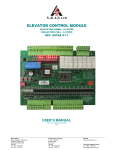
S. & A.S. LTD ELEVATOR CONTROL MODULE VERSION 3.3A REF. MICROZED V3.3A USER’S MANUAL FOR S/W VERSION 1.00.2 1516 Beirut Office: Boutros Building 1st Basement Cheikh-el-Ghabi Street Ghabi Beirut 2068 7808 Lebanon Tel: +961 1 216 994 Fax:+961 1 339 600 Headquarters & Factory: S. & A. S. Building Seaside Road Jieh Chouf Lebanon Tel: +961 7 996 333 Fax:+961 7 996 116 Website: www.sascontrollers.com Technical Support & Email: Tel: +961 71 996 333 [email protected] 1 GENERAL DESCRIPTION 3 MAIN FEATURES..................................................................................................................................................... 3 1.2 TECHNICAL DATA ................................................................................................................................................... 4 2 TERMINAL DESCRIPTION 5 2.1 TERMINAL LAYOUT ................................................................................................................................................ 5 2.2 INPUT TERMINALS ................................................................................................................................................. 5 2.3 OUTPUT TERMINALS ............................................................................................................................................. 6 2.3.1 OUTPUT TERMINALS FOR AC 1 SPEED AND AC 2 SPEED ....................................................................... 6 2.3.2 OUTPUT TERMINALS FOR VVVF ................................................................................................................... 6 2.3.3 OUTPUT TERMINALS FOR HYDRAULIC ....................................................................................................... 7 2.4 CALL TERMINALS ................................................................................................................................................... 7 2.4.1 CALL TERMINALS LOCATED ON BOARD ..................................................................................................... 7 2.4.2 CALL TERMINALS ON EXTENSION BOARDS ............................................................................................... 8 2.5 COMMUNICATION TERMINALS CONNECTION ................................................................................................. 11 3 CONTENTS OF PAGES DISPLAYED ON LCD 12 4 VIEWING FAULTS AND FAULTS DESCRIPTION 12 4.1 HOW TO VIEW THE FAULTS ............................................................................................................................... 12 4.2 HOW TO ERASE THE FAULTS ............................................................................................................................ 12 4.3 FAULT CODE DESCRIPTION ............................................................................................................................... 13 5 MENU 14 5.1 PASSWORD ........................................................................................................................................................... 14 5.2 ACCESSING THE MENU....................................................................................................................................... 14 5.3 MENU DESCRIPTION ........................................................................................................................................... 15 5.3.1 MENU TRANSLATION INTO FRENCH AND ARABIC .................................................................................. 19 5.3.2 ON-BOARD CALL REGISTRATION FUNCTION ........................................................................................... 20 5.3.3 ON-BOARD INSPECTION OPERATION ....................................................................................................... 20 5.3.4 CARCALL CANCELLATION ........................................................................................................................... 20 5.3.5 DOOR MAPPING FOR TWO DOOR ENTRANCE ......................................................................................... 20 6 DESKTOP FIRMWARE UPGRADE 21 6.1 INSTALLING THE MZ3.3A FIRMWARE UPGRADE SOFTWARE ....................................................................... 21 6.2 INSTALLING THE MZ3.3A USB DRIVER ............................................................................................................. 21 6.2.1 DRIVER SETUP FOR WINDOWS VISTA/WIN7 ............................................................................................ 21 6.2.2 DRIVER SETUP FOR WINDOWS XP ............................................................................................................ 23 6.3 FIRMWARE UPGRADE PROCESS ...................................................................................................................... 24 7 GOOGLE STORE FIRMWARE UPGRADE 26 7.1 INSTALLING THE SASPTOOL FIRMWARE APPLICATION ON THE MOBILE .................................................. 26 7.2 FIRMWARE UPGRADE PROCESS ...................................................................................................................... 26 8 APPENDIX A 28 2 1 GENERAL DESCRIPTION The MICROZED V3.3A elevator controller module contains all the necessary components to control the elevator and to simultaneously insure the protection of the elevator and user against faulty conditions. These controllers can operate in a group of up to 4 elevators. In addition, this module has a user-friendly interface consisting of one 24-characters by 2-lines LCD alphanumeric display and three push buttons to access the different pages, menus and parameters editing (the display is sold separately). All spare outputs are user configurable. The firmware could be upgraded on site. Furthermore, the MICROZED V3.3A controller has a serial RS485 port enabling it to be connected to a hand held diagnostic tool (sold separately). A new optional interface is available and it has a USB port, an ethernet port for internet connection and an RS232 port for a GSM modem connection. Special software, available from S. & A.S. ltd., displays the general status of the elevator and the most recent 15 faults on the computer screen. 1.1 MAIN FEATURES Platform Type Mode Self diagnostic Status information Fault count Shaft information Indicator signal Number of stops Door type Door controls4 Door parking status Floor Stop time Main landing Car light Automatic return Gong output Inspection mode6 7 Reservation Minimum load1 Full load8 Emergency stop Firemen operation9 Terminals Group operation Communication Software Carcall cancellation Firmware update ARM Microcontroller AC 1 speed – AC 2 speed – VVVF – Hydraulic1 Simplex or group1 Fault messages describing common faults related to periphery inputs Status of the elevator and the door are permanently displayed Count of level II faults (refer to section 4.1) is permanently displayed End of shaft in the up direction End of shaft in the down direction Slow down and final stop in the up direction Slow down and final stop in the down direction Door zone (recommended but not obligatory) 2 Car position is saved following a power failure Gray code, provided by the board (binary or other types can be supported optionally) 8, 163, 243 or 323 stops collective down – 6, 113, 163 or 223 stops collective selective1 1 Swinging, automatic or ½ automatic door Input for re-open, photocell and door jam switch + input to bypass closing delay5 Parking with door opened or door closed1 1 Can be defined by the user Can be defined as any stop1 Automatic switch off after preset time To main landing floor Three seconds pulse to signal the arrival of the elevator For installation and maintenance purposes using slow speed/ Inspection speed System responds to car calls only, outside calls are canceled Car calls are canceled if car stops twice on a car call and no passengers exit car Only car calls are served, outside calls are still registered Car is stopped, car calls canceled, outside calls retained, car restarts on a car call Evacuation to ground floor, blocking all calls and allowing firemen operation All terminals are individually labeled according to function to facilitate identification RS485 port ready for group operation Optional board (MCI-HUB) available for remote monitoring and control directly by PC or by internet. Connection via Ethernet or via RS232 GSM modem. Monitoring and controlling elevator installation, software runs under WindowsTM A registered carcall cancelled when user double-clicks it User desktop interface to upgrade firmware on site Google store Application: SASPTool 1 Selection by presetting a parameter in the menu, refer to section 5. When power returns, elevator resumes from where it was without the need of a homing trip unless Power-ON homing is enabled, refer to section 5. 3 Requires optional extension boards. 4 For automatic or ½ automatic door only. 5 Activated by a push button in the car. 6 Activated by an external key switch and two push buttons. 7 Activated by a key switch in the car. 8 Activated by an external contact. 9 Activated by a key switch in the main landing floor. 2 3 1.2 TECHNICAL DATA Supply voltages Inputs Outputs Call terminals Indicator outputs Connection Board supply: 17vac +15% -25% - 120mA Periphery supply: 22vdc +15% -25% Each input has a led to indicate its status – all inputs are optically isolated Input active voltage level is 22vdc Each output has a led to indicate its status – all outputs are optically isolated Each output is capable of driving the negative side of a contactor or relay coil operating from a dc voltage as high as 90 volts with currents as high as 3 amperes1 Each call has a led to indicate its status Each call terminal consists of a combined input/output which is optically isolated Call active voltage level is zero volts (GND) Call terminals are capable of driving lamps up to 3 watts operating on 22vdc Each call terminal is protected by an additional output transistor Each output has a led to indicate its status – all outputs are optically isolated Output active voltage level is 22vdc Screw type, plug-in connectors 1 Care should be taken to add a freewheeling diode in parallel with the coil of each contactor or relay driven from the board. Failure to do so will jeopardize the operation of the output transistor and will eventually damage it. 4 COM DATA1 DATA2 CT3 CT2 CT1 CT0 17V~ 17V~ CT9 CT8 CT7 CT6 CT5 CT4 CT15 CT14 CT13 CT12 CT11 CT10 FRMN SPRE IN PTC A PTC B EVACUATION OVERLD DZ SPRE1 E D C B A CLSE NDLY LS EO LS EC FULL VVVF SDFS UP SDPF DN EOS UP EOS DN INSP UP INSP DN 2.2 OPN CLSE CAM LOW SPD HIGH SPD UP DIR DN DIR TERMINAL LAYOUT P +22V GND (-) SPRE2 ARO UP ARO DN LGHT 2.1 TERMINAL DESCRIPTION INSP EN RSV STP CONT RDY SFTY ON RE OPN 2 INPUT TERMINALS SDFS_UP SDFS_DN EOS_UP EOS_DN INSP_UP INSP_DN INSP_EN RSV STP CONT RDY SFTY ON RE_OPN CLSE_NDLY LS_EO LS_EC FULL VVVF DZ FRMN SPRE IN PTC A PTC B EVACUATION OVERLD Slow down and final stop in the up direction magnetic switch Slow down and final stop in the down direction magnetic switch End of shaft in the up direction magnetic or limit switch End of shaft in the down direction magnetic or limit switch Inspection up Inspection down Inspection enable (when input is inactive) Reservation – outside calls are canceled (when input is active) Emergency stop (when input is inactive) Should be active prior to initiating travel (ensures that all contactors are in their OFF state) Should be active when lift is moving (used to read the status of the safety circuit) Re-open for automatic door (when inactive) / door closed for swinging door (when active) Bypasses reclosing delay in automatic door Limit switch end of opening Limit switch end of closing Full load – only car calls are served with outside calls still being registered (when input is active) A VVVF signal that prompts the controller that the drive has engaged the mechanical brake Door zone magnetic switch Firemen switch Spare input Input from the PTC Input from the PTC A Rescue signal that prompts the controller that it is in evacuation mode Overload switch 5 2.3 2.3.1 OUTPUT TERMINALS OUTPUT TERMINALS FOR AC 1 SPEED AND AC 2 SPEED P +22V GND SPRE2 ARO_UP ARO_DN LGHT OPN CLSE_CAM LOW_SPD HIGH_SPD UP_DIR DN_DIR SPRE1 E D C B A 2.3.2 Biasing voltage from periphery supply – positive side1 1 Biasing voltage from periphery supply – negative side Gong or Cam contactor if ½ automatic door is selected as door type Up direction arrow Down direction arrow Car light relay Open door relay or contactor2 Cam contactor3 / Close relay or contactor2 Low speed contactor4 High speed contactor4 Up direction contactor Down direction contactor Spare output Floor information E for Gray code indicator Floor information D for Gray code indicator Floor information C for Gray code indicator Floor information B for Gray code indicator Floor information A for Gray code indicator OUTPUT TERMINALS FOR VVVF P +22V GND SPRE2 ARO_UP ARO_DN LGHT OPN CLSE_CAM LOW_SPD HIGH_SPD UP_DIR DN_DIR SPRE1 E D C B A Biasing voltage from periphery supply – positive side1 Biasing voltage from periphery supply – negative side1 Gong or Cam contactor if ½ automatic door is selected as door type Up direction arrow Down direction arrow Car light relay Open door relay or contactor2 Cam contactor3 / Close relay or contactor2 Low speed relay5 High speed relay5 Forward relay Reverse relay Spare output Floor information E for Gray code indicator Floor information D for Gray code indicator Floor information C for Gray code indicator Floor information B for Gray code indicator Floor information A for Gray code indicator 1 Although this is not an output, it is listed with the outputs for convenience. For automatic or ½ automatic door only. 3 For swinging door. 4 Do not connect for AC 1 speed elevators. 5 Sets the speed reference for the VVVF drive. If only HIGH_SPD output is active, the high speed is selected. If both HIGH_SPD and LOW_SPD outputs are active, the slow speed is selected. If only LOW_SPD is active, inspection speed is selected. 2 6 2.3.3 OUTPUT TERMINALS FOR HYDRAULIC Biasing voltage from periphery supply – positive side1 Biasing voltage from periphery supply – negative side1 Gong or Cam contactor if ½ automatic door is selected as door type Up direction arrow Down direction arrow Car light relay Open door relay or contactor2 Cam contactor3 / Close relay or contactor2 Releveling relay High speed valve Pump delta contactor Down direction valve Pump star contactor4 Floor information E for Gray code indicator Floor information D for Gray code indicator Floor information C for Gray code indicator Floor information B for Gray code indicator Floor information A for Gray code indicator P +22V GND SPRE2 ARO_UP ARO_DN LGHT OPN CLSE_CAM LOW_SPD HIGH_SPD UP_DIR DN_DIR SPRE1 E D C B A 2.4 CALL TERMINALS 2.4.1 CALL TERMINALS LOCATED ON BOARD The allocation of calls on call terminals depends on whether one or more extension boards are present. The table below shows how the calls are allocated: Without Extension CT15 CT14 CT13 CT12 CT11 CT10 CT9 CT8 CT7 CT6 CT5 CT4 CT3 CT2 CT1 CT0 17V~ 17V~ Down Collective5 Down 7 Full Collective Down 5 Down 6 Down 4 Down 5 Down 3 Down 4 Down 2 Down 3 Down 1 Down 2 Up 4 Down 1 Up 3 Down 0 Up 2 Car 7 Up 1 Car 6 Up 0 Car 5 Car 5 Car 4 Car 4 Car 3 Car 3 Car 2 Car 2 Car 1 Car 1 Car 0 Car 0 Board power supply – 17v~ a6 Board power supply – 17v~ b6 With 1 Extension CT15 CT14 CT13 CT12 CT11 CT10 CT9 CT8 CT7 CT6 CT5 CT4 CT3 CT2 CT1 CT0 17V~ 17V~ Down Collective5 Car 15 Full Collective Up 4 Car 14 Up 3 Car 13 Up 2 Car 12 Up 1 Car 11 Up 0 Car 10 Car 10 Car 9 Car 9 Car 8 Car 8 Car 7 Car 7 Car 6 Car 6 Car 5 Car 5 Car 4 Car 4 Car 3 Car 3 Car 2 Car 2 Car 1 Car 1 Car 0 Car 0 Board power supply – 17v~ a6 Board power supply – 17v~ b6 1 Although this is not an output, it is listed with the outputs for convenience. For automatic or ½ automatic door only. For swinging door. 4 Do not connect for direct on line configuration. 5 Down calls starting at ground floor level and below are internally converted to up calls. The position of the ground floor is determined by setting the number of basements; refer to section 5. For instance if there are no basements, then the ground floor is on the first level and consequently Down 0 call will be internally interpreted as an Up 0 call. 6 Although this is not a call, it is listed with the calls for convenience. 2 3 7 With 2 or 3 Extensions CT15 CT14 CT13 CT12 CT11 CT10 CT9 CT8 CT7 CT6 CT5 CT4 CT3 CT2 CT1 CT0 17V~ 17V~ 2.4.2 Down Collective1 or Full Collective Car 15 Car 14 Car 13 Car 12 Car 11 Car 10 Car 9 Car 8 Car 7 Car 6 Car 5 Car 4 Car 3 Car 2 Car 1 Car 0 Board power supply – 17v~ a2 Board power supply – 17v~ b2 CALL TERMINALS ON EXTENSION BOARDS If more than one extension board is required, the boards should be cascaded. The table below shows how the calls are allocated on the extension board #1: With 1 Extension P +22V GND EC0 EC1 EC2 EC3 EC4 EC5 EC6 EC7 EC8 EC9 EC10 EC11 EC12 EC13 EC14 EC15 Down Collective1 Full Collective Biasing voltage from periphery supply – positive side2 Biasing voltage from periphery supply – negative side2 Down 0 Up 5 Down 1 Up 6 Down 2 Up 7 Down 3 Up 8 Down 4 Up 9 Down 5 Down 1 Down 6 Down 2 Down 7 Down 3 Down 8 Down 4 Down 9 Down 5 Down 10 Down 6 Down 11 Down 7 Down 12 Down 8 Down 13 Down 9 Down 14 Down 10 Down 15 - 1 Down calls starting at ground floor level and below are internally converted to up calls. The position of the ground floor is determined by setting the number of basements; refer to section 5. For instance if there are no basements, then the ground floor is on the first level and consequently Down 0 call will be internally interpreted as an Up 0 call. 2 Although this is not a call, it is listed with the calls for convenience. 8 With 2 Extensions P +22V GND EC0 EC1 EC2 EC3 EC4 EC5 EC6 EC7 EC8 EC9 EC10 EC11 EC12 EC13 EC14 EC15 With 3 Extensions P +22V GND EC0 EC1 EC2 EC3 EC4 EC5 EC6 EC7 EC8 EC9 EC10 EC11 EC12 EC13 EC14 EC15 Down Collective1 Full Collective Biasing voltage from periphery supply – positive side2 Biasing voltage from periphery supply – negative side2 Down 0 Up 0 Down 1 Up 1 Down 2 Up 2 Down 3 Up 3 Down 4 Up 4 Down 5 Up 5 Down 6 Up 6 Down 7 Up 7 Down 8 Up 8 Down 9 Up 9 Down 10 Up 10 Down 11 Up 11 Down 12 Up 12 Down 13 Up 13 Down 14 Up 14 Down 15 - Down Collective1 Full Collective Biasing voltage from periphery supply – positive side2 Biasing voltage from periphery supply – negative side2 Down 0 Up 0 Down 1 Up 1 Down 2 Up 2 Down 3 Up 3 Down 4 Up 4 Down 5 Up 5 Down 6 Up 6 Down 7 Up 7 Down 8 Up 8 Down 9 Up 9 Down 10 Up 10 Down 11 Up 11 Down 12 Up 12 Down 13 Up 13 Down 14 Up 14 Down 15 Up 15 1 Down calls starting at ground floor level and below are internally converted to up calls. The position of the ground floor is determined by setting the number of basements; refer to section 5. For instance if there are no basements, then the ground floor is on the first level and consequently Down 0 call will be internally interpreted as an Up 0 call. 2 Although this is not a call, it is listed with the calls for convenience. 9 The table below shows how the calls are allocated on the extension board #2: With 2 Extensions P +22V GND EC0 EC1 EC2 EC3 EC4 EC5 EC6 EC7 EC8 EC9 EC10 EC11 EC12 EC13 EC14 EC15 With 3 Extensions P +22V GND EC0 EC1 EC2 EC3 EC4 EC5 EC6 EC7 EC8 EC9 EC10 EC11 EC12 EC13 EC14 EC15 Down Collective1 Full Collective 2 Biasing voltage from periphery supply – positive side Biasing voltage from periphery supply – negative side2 Car 16 Down 1 Car 17 Down 2 Car 18 Down 3 Car 19 Down 4 Car 20 Down 5 Car 21 Down 6 Car 22 Down 7 Car 23 Down 8 Down 16 Down 9 Down 17 Down 10 Down 18 Down 11 Down 19 Down 12 Down 20 Down 13 Down 21 Down 14 Down 22 Down 15 Down 23 Down Collective1 Full Collective 2 Biasing voltage from periphery supply – positive side Biasing voltage from periphery supply – negative side2 Car 16 Down 1 Car 17 Down 2 Car 18 Down 3 Car 19 Down 4 Car 20 Down 5 Car 21 Down 6 Car 22 Down 7 Car 23 Down 8 Car 24 Down 9 Car 25 Down 10 Car 26 Down 11 Car 27 Down 12 Car 28 Down 13 Car 29 Down 14 Car 30 Down 15 Car 31 Down 16 1 Down calls starting at ground floor level and below are internally converted to up calls. The position of the ground floor is determined by setting the number of basements; refer to section 5. For instance if there are no basements, then the ground floor is on the first level and consequently Down 0 call will be internally interpreted as an Up 0 call. 2 Although this is not a call, it is listed with the calls for convenience. 10 The table below shows how the calls are allocated on the extension board #3 With 3 Extensions P +22V GND EC0 EC1 EC2 EC3 EC4 EC5 EC6 EC7 EC8 EC9 EC10 EC11 EC12 EC13 EC14 EC15 2.5 Down Collective Full Collective 1 Biasing voltage from periphery supply – positive side Biasing voltage from periphery supply – negative side1 Down 16 Car 16 Down 17 Car 17 Down 18 Car 18 Down 19 Car 19 Down 20 Car 20 Down 21 Car 21 Down 22 Up 16 Down 23 Up 17 Down 24 Up 18 Down 25 Up 19 Down 26 Up 20 Down 27 Down 17 Down 28 Down 18 Down 29 Down 19 Down 30 Down 20 Down 31 Down 21 COMMUNICATION TERMINALS CONNECTION COM, DATA1 and DATA2 should be connected in all controllers in a group mode. CAT5 cable must be used where the shield is connected to COM and one twisted pair is used for DATA1 and DATA2 1 Although this is not a call, it is listed with the calls for convenience. 11 3 CONTENTS OF PAGES DISPLAYED ON LCD Page 1 Page 2 Page 33 Page 44 Page 5 Page 6 Page 7 4 4.1 Company name, Software version Time, date and day of the week1 1st line: Elevator status Normal, Inspection, Homing, Reservation, Full Load, Landing, Fault Speed Hi, Lo2 Direction , 2 Floor FL ## 2nd line: Door status: For swinging door Opened, Closed, Locking, Locked For automatic & 1/2 automatic door Opened, Closed, Opening, Closing, ½open, Unknown Current fault description Fault Log with the possibility of viewing the last 99 faults with the floor where each fault has occurred Homing trip request Summary of the elevator settings: Elevator mode and board address Collective mode Door type Drive type Count of extensions Minimum load feature (MD: Disabled, ME: Enabled) Main Landing feature (LD: Disabled, LE: Enabled) 5 Parking Door status (PDC: Closed, PDO: Opened) Boards detected On Bus (supported only when diagnostic tool is used) VIEWING FAULTS AND FAULTS DESCRIPTION HOW TO VIEW THE FAULTS Faults detected by the board are divided into three levels: 1. Level I faults: faults that block the elevator when they occur. But the elevator can resume operation right after the fault disappears. 2. Level II faults: faults that can be tolerated for a few occurrences before the elevator is blocked by the board. The count of level II faults is shown on LCD Page 4. When the count of level II faults reaches the preset number6, the board will block the elevator. 3. Level III faults: faults that the board considers to be fatal and will block any further operation of the elevator. Pressing the Select push button while on LCD Page 4 will prompt the board to start displaying the last 99 faults saved in memory. The board begins by displaying the last fault followed by the floor number where the fault occurred. Press Previous or Next push buttons to display the previous or next fault. 4.2 HOW TO ERASE THE FAULTS To erase the faults as well as the count of level II faults from memory, enter the menu, go to Empty Fault Log and press Select push button. You will be prompted to confirm your request. If Yes is pressed all faults are erased, if No is pressed, faults are not affected. 1 When the RTC device is installed. When the elevator is moving. 3 Appears only if there is a fault. 4 Appears only if fault log is not empty. 5 Relevant in automatic or ½ automatic door. Refer to section 5. 6 Refer to section 5. 2 12 4.3 FAULT CODE DESCRIPTION Fault Message Fault Description Sfty opnd in travl Safety circuit and/or door opened 8 during travel Sfty opnd in travl Safety circuit opened during travel Lock opnd in travl Door clsd, not sfty Fail to lock cam Fail to close door EOS_UP Fault EOS_DN Fault Shaft Info Flt Shaft Info Flt No EOS Info Emergency stop Car is jammed Door is obstructed Fail to open door 9 Operat. days exprd Contactors jammed Motor overheating Level I 9 Door lock circuit opened during travel8 Safety circuit failed to close after door 9 closing Failure in locking door after 3 attempts8 Failure in closing door9 EOS-UP fault EOS-DN fault SDFS-UP or SDFS-DN or EOS-UP or EOS-DN or DZ3 fault SDFS-UP or SDFS-DN or EOS-UP 3 or EOS-DN or DZ fault EOS-UP and EOS-DN faults (both open) Emergency stop Motor has been powered for 25 sec, car did not move Door has been opened for more than Door Obstructed Del5 Failure in opening door Preset number of operating days expired All orders on contactors were removed, one contactor or more is still engaged Motor temperature has exceeded its maximum allowable operating temperature I I Action taken Waits for safety circuit to close Waits for safety circuit to close, cancels calls 1 if fault persists more than 5sec Waits for lock circuit to close, cancels calls if fault persists more than 5sec1 1 I Cancels calls and opens door I Cancels calls1 II III III Cancels calls, opens door1 2 Blocks elevator 2 Blocks elevator II Performs a homing trip II Performs a homing trip III Blocks elevator I Waits for a car call to resume III Blocks elevator I Waits for door to close II Close door and resume III Blocks elevator I Waits all contactors to be released I Elevator is stopped at the nearest floor. Waits for the motor to cool down 4 2 6 7 External err.(VVVF) VVVF external error I Elevator is stopped at the nearest floor. Waits for external VVVF error to be removed Uncontrolled Move In VVVF, when Door zone is installed, The lift without Up/Down command in Normal operation goes out of zone III Blocks elevator 2 The last 15 faults are permanently stored along with the time, date of occurrence and the floor where the error occurred. Faults can be accessed through the Select option on LCD Page 4. 1 Waits for a call to resume operation. When the cause of the fault is diagnosed and fixed, empty the faults log or request a homing trip so that the elevator resumes operation. When DZ magnetic switch is installed. Refer to section 5. 4 When the cause of the fault is diagnosed and fixed, the elevator will automatically resume operation. 5 Relevant in duplex mode only - Refer to section 5. 6 In case of automatic door, waits for obstacle to clear. 7 To recover from this fault, access menu and clear the count of elapsed days. Refer to sections 5. 8 For swinging or ½ automatic door. 9 For automatic door. 2 3 13 5 5.1 MENU PASSWORD A password is required for accessing the menu. The password consists of 6 digits. Two passwords can access the menu. The first is provided by S. & A.S. Co. Ltd. and is referred to as client password. This password can only be changed by S. & A.S. Co. Ltd. The second password is referred to as the user password. The user password can be modified in the menu. The client password accesses all the items in the menu whereas the user password is denied access to all menu items related to time restriction. 5.2 ACCESSING THE MENU 1 To access the menu, press the right most push button on the LCD Display while on pages 1, 2, 3 or 6 . You will be prompted to enter a password. The first digit on the left starts blinking. Use the left most push button to decrement the digit and the middle push button to increment the digit. When the desired digit is reached, push the right most push button. The digit is accepted and replaced by “*”. The next digit starts blinking. Repeat the above procedure for all remaining five digits. If you have entered the right password, access to the menu will be granted, otherwise access will be denied. Note that the push buttons have dynamic functions and their functions are at all times shown on the lower line of the display. 1 Refer to section 3 14 5.3 MENU DESCRIPTION What you see on the display V1.00.2 Normal FLxx View Faults (Fatal=--) Homing trip? Simplex(1)Full Swinging Simulate calls Inspection operation Boards detected On Bus Enter Password Empty Fault Log Light Time Floor Stopping Time Parking Door Description and Comments Hydraulic Star Time VVVF Start Delay VVVF/ Hyd Stop Delay Empties the fault log Car light turn off delay in sec Time between travel in sec The parking status of the door When enabled, the RE OPN input is bypassed to clear any obstacle blocking the door/ When disabled and the door is held open, it is considered to be obstructed after this delay Star starting time of the hydraulic pump The delay in sec between providing direction and speed reference outputs The delay in sec between removing direction and speed reference outputs Gong Time The gong time in seconds Door Nudging/Obst Minimum Load Main Landing PTC Detection Power On Homing 1 6 When this feature is enabled, car calls are canceled if car stops twice on a car call and no passengers exit car Sets the landing floor along with the delay before making a main landing trip given that the elevator has no calls to serve When this feature is enabled, the motor PTC is continuously monitored When enabled, the elevator makes a homing trip upon every power-on When disabled following power on and if lift is not parked on a floor , the controller will take it to the nearest floor traveling in the same direction prior to power failure When set to NoDZ and the lift is on a floor, no action is taken. Otherwise, lift will do homing trip upon power-on V means visible A means accessible NV means not visible 4 NA means not accessible 5 N/A means not assigned 6 If there are 2 close floors or the elevator slips more than ½ distance of the floor, “Power On Homing” must be set to enabled 2 3 Normal Insp Mode Mode V1 V V V If faults exist V V V V 2 3 4 V/A NV /NA NV/NA V/A Always V/A V/A if faults exist A A A A A A Visibility Condition 5 Range Default Value N/A N/A Auto/Half Auto door 5 to 99sec 1.0 to 9.9sec Opened/Closed 10sec 3.0sec Closed Ena/ Dis, 5 to 99sec Dis, 90sec A A N/A A A A A A A 0.0 to 9.9sec -9.9 to 9.9sec -9.9 to 9.9sec 1.0sec 0.0sec 3.0sec A A Hydraulic elevator VVVF drive VVVF drive Spare1 or Spare2 or Spare3 or Spare4 function=gong, CC+, CC-, HC+, HC- 0.0 to 7.5sec 3.0sec A A N/A Disabled/Enabled Disabled A A N/A A A N/A A A N/A None, 0… 310’10” to 30’59” Disabled/Enabled Disabled/Enabled/ NoDZ None Disabled Disabled What you see on the display Light Inverted Re-leveling Description and Comments When this feature is enabled, the output logic of the car light is inverted When preset to selective, the re-leveling is done only when the door is closed and the elevator has no calls to serve 2Side Door F. When this feature is enabled, the elevator is prevented from crossing the end of shaft limits in inspection mode The delay in seconds between the closing of the swinging door and the Cam /Close signal Maximum delay in seconds to Sfty on after engaging the cam The delay in seconds between providing the Cam/Close signal and the direction/Speed outputs nd Enable to activate 2 door for cabin Auto door mapping Floor # x Door Side CC Cancelation EOS During Insp Cam close delay Cam engage time Contactor start del Time Restrict. Elapsed Cnt Of Days Preset Count Of Days Max. Count Of Err. Amendment A3 Car jammed delay Auto Door Operation Inspection speed Ramp to stop w Insp Basements Door Type Permanent Close Permanent Open RE-OPN i/p Normal Mode A Insp Mode Range Default Value A Visibility Condition N/A Disabled/Enabled Disabled A A Hydraulic elevator Always/Selective Selective/ Disabled A A N/A Disabled / Enabled Disabled A A Swinging door 0.0 to 7.5sec 0.0 sec 1 A Swinging door 5 to 99sec 5 sec A 2 A A N/A 0.0 to 7.5sec 0.5sec A A Disabled / Enabled Enabled Gives access to submenu “Floor # x Door Side” A A N/A N/A Selects the door side for each floor When enabled, a registered carcall can be canceled by double clicking it When this feature is enabled, the elevator is blocked when the number of days counted reaches the preset count of days Shows the number of days elapsed since the Time Restriction feature was enabled or since the last reset of the Elapsed Cnt Of Days Sets the maximum count of days of operation Sets the maximum count of Level II faults before blocking the elevator When this feature is enabled and no moving orders are given, the elevator is blocked when door zone input status varies from On to Off The car is considered jammed after this delay. The Auto door is considered jammed after this delay Sets the inspection speed When this feature is enabled, the lift will ramp to stop when the inspection up or down button is released Sets the count of basements A A A A Auto/Half Auto door 2Side Door F. Enabled N/A N/A A / B / Both Disabled / Enabled Both Enabled A A Client P/W Disabled / Enabled Disabled A A Client P/W N/A A A A A 1 to 999 None, 1…99 1 10 A A Disabled / Enabled Disabled A A A A A A Client P/W N/A VVVF Drive & DZ installed N/A Auto/Half Auto door AC2 Speed Dis, 5 to 99sec Dis, 5 to 99sec Lo/Hi 25sec 20sec Lo Selects the type of the elevator door. Select ½ automatic door if there is an electric cam to lock the door in addition to the automatic door drive. When this feature is enabled, the door closing signal is permanently engaged during travel (required for specific types of door drives) When this feature is enabled, the door opening signal is permanently engaged when the door is totally opened Sets the logic of the re-opn input A A VVVF drive Dis/Ena Dis NA3 A N/A 0 NA A N/A 0 to 9 Swinging/ Automatic / ½ Automatic A A Automatic door Disabled/Enabled Disabled A A Automatic door Disabled/Enabled Disabled A A N/A no/nc nc Swinging 1 A means accessible N/A means not assigned 3 NA means not accessible 4 Appears only if drive is VVVF and Encoder is installed 2 16 What you see on the display Description and Comments Normal Mode Insp Mode Visibility Condition Range Default Value A A Auto/Half Auto door N/Y N Pre-opening When this feature is set to Y and the door is counting Floor Stopping Time to start closing, Then if the photocell is cut, Restart counting Floor Stopping Time When this feature is installed, the controller looks for the DZ magnetic switch signal upon every floor stop. The absence of this signal on floor level prompts the controller to register a Level II fault and to perform a homing trip When this feature is enabled, door starts opening when DZ is reached First Stop Selects the gray code output for the first stop Collective Selects between collective selective, down collective and multiplexing modes NA A N/A Full / Down / APB / Down Carcall priority NA A Collective#APB N/Y N NA A N/A Mode Gives priority to car calls over hall calls Sets the count of extension boards installed and thus the distribution of the car and land calls Selects between simplex and group modes. NA A N/A Drive Selects the drive type NA A N/A Intermediat Speed Selects when intermediate speed is used NA A Homing Speed Select the homing speed NA A Reset time on re-opn Door Zone Extension Boards Spare1 Spare2 1 Sets the Spare1 output function Sets the Spare2 output function A A N/A None/Installed None A A DZ installed Disabled / Enabled Disabled A A N/A 0/1 0 NA NA A A 1 None, 1, 2 or 3 None VVVF drive Simplex/Group AC 2speed / Hydraulic / VVVF None, 1FL, 2FL Simplex AC 2speed None VVVF drive Insp/ Hi/ Int Insp Not Hydraulic Fan/Gong/ BaseBlock/ DoorB Close/DoorB Open/ Int.Speed/Down Arrow/Up Arrow/1/2 Auto cam/Hyd.Star/Car Light/Open/Cam Close/Dn Direction/Up Direction/Low Speed/High speed/Slowing Down/Evac Mode/Insp Mode/Door Buzzer /Out Of Serv. Fan Not 1/2 Auto. door Fan/Gong/ BaseBlock/ DoorB Close/DoorB Open/ Int.Speed/Down Arrow/Up Arrow/1/2 Auto cam/Hyd.Star/Car Light/Open/Cam Close/Dn Direction/Up Direction/Low Speed/High speed/Slowing Down/Evac Mode/Insp Mode/Door Buzzer /Out Of Serv. Gong N/A means not assigned 17 What you see on the display Normal Mode Insp Mode Sets the passenger capacity of the elevator A A Visibility Condition Group mode Display Type Selects the hall and car display type A A N/A Total Trips Counter for the number of trips made by the elevator. The counter value can be edited and modified A A N/A 0 to 999999 N/A English Passenger Capacity Language Board Address User Password Co. Max Trips/h Adjust Time Adjust Date Adjust Day Upload settings to DT Dnload settings from DT Firmware Update Load Factory Settings Exit Menu Temporarily 1 2 Description and Comments Sets the language Sets the address of the board (each board in a group must have a unique address) Shows and edits the user password Shows and edits the company name displayed on the first page Shows the maximum recorded count of trips in one hour along with the time of the day when it happened Sets the time of the day Sets the date Sets the day of the week Upload the settings from MicroZed to DT Download the settings from DT to MicroZed Upgrade the firmware on site Loads the settings of the factory Exits the menu allowing reentry with no password for 10 minutes Range 1 to 99 Gray / Binary / Enhanced Default Value 5 Gray A A N/A English / French / Arabic /Swedish A A N/A 1 to 4 1 A A A A N/A N/A ****** 16 characters 000000 A A N/A N/A1 A A A A NA2 NA NA A A A A A A A A A N/A N/A N/A DT connected DT connected Client P/W N/A N/A N/A N/A Mon to Sun N/A N/A means not assigned NA means not accessible 18 5.3.1 MENU TRANSLATION INTO FRENCH AND ARABIC ENGLISH FRENCH V1.00.2 Normal FLxx View Faults (Fatal=--) Homing trip? Simplex(1)Full Swinging Simulate calls Inspection operation Boards detected On Bus Enter Password Empty Fault Log Light Time Floor Stopping Time Parking Door Door Nudging/Obs Hydraulic Star Time VVVF Start Delay VVVF/Hyd Stop Delay Gong Time Minimum Load Main Landing PTC Detection Power On Homing Light Inverted Re-leveling EOS During Insp Cam close delay Cam engage time Contactor start del 2Side Door F. Auto door mapping Floor # x Door Side CC Cancelation V1.00.2 Normal Etxx Voir Fautes (Fatal=--) Parcours d'initialisat. Simplex(1)Sel. Battante Simuler appels Operation Revision Cartes detectees sur Bus Entrer Le Code Vider Journal De Fautes Duree D'eclairage Duree Arret Etage Stationemt Porte Porte Coup/Coincee Duree Etoile Hydr. Delai Depart VVVF Delai Arret VVVF Duree Gong Charge Minimale Retour Et.Pr. Detection PTC Initial. & EDL Eclair. Inverse Corrig. Niveau EOS Et Revision Delai fermetu. serr Duree fermetu. serr Delai Depart Cont. 2Portes later. Carte de la Porte Auto. Floor # x Door Side Annulat. Appel Amendment A3 Amendement A3 Time Restrict. Elapsed Cnt Of Days Preset Count Of Days Max. Count Of Err. Car jammed delay Auto Door Operation Inspection speed Compteur Jours Jours Deroules Nb. De Jours Desires Nbre Max. D'erreurs Delai cabine bloquee Operation porte auto. Vitesse de Revision Ramp avec revision Sous-sols Type De Porte Ferm.Permanente Ouvr. Permanente Entree RE-OPN Reset dure apres reopn Door Zone Pre-ouverture Premier Arret Collective Priorite pour cabine Nbre D'extensions Mode Moteur Vitesse intermed. Vitesse initialisat. Spare1 Spare2 (24V) Nbre de personnes Ramp to stop w Insp Basements Door Type Permanent Close Permanent Open RE-OPN i/p Reset time on re-opn Door Zone Pre-opening First Stop Collective Carcall priority Extension Boards Mode Drive Intermediat Speed Homing Speed Spare1 Spare2 Passenger Capacity SWEDISH Uppstart Simplex(1)Ned Slagdör Simulera Körning InspeKtions Körning Kretskort det.Pâ Bus Ange Lösenord Radera gallog Körbelysning tid Stopptid Partering Dörr Dörrfotocell Förd Y/D Start tid Fördr.start VVVF Fördr.stop VVVF/Hyd GongSignal tid Minimum Last Entre plan PTC Kontroll Sp till âterKör Utg för bel inv Efterinstäl. EOS vid insp. Förd av läsbana Tid lâsbana dragen Kontaktor förd.Start Tvä sidodörrar Auto dörren mapping Floor # x Door Side Korg Appel Anul ändring Tidsbegränsad Räkna dagar son gâtt Reset av dagräknare Max antal fel Fördr.pga.överlast Aut dörr styrning Inspektion shast ighet Stop ramp inspekt. Källarplan Dörrtyp Alltid stängd Alltid Oppen Ing för âteröppening Tid efter âteröpenning Dörr zon Tidig dörröppn Första stopp Kollektiv Prioritet Korgdest Expansionskät Mode Igâng Medelhastighet Äterkorn.hastighet Extra utg1 Extra utg2 Antal Passagerare ARABIC 1.00.2 طأ عادي (--=اظھار األخطاء )حاسم رحلة أولية ( نزول باب عادي١)مفرد محاكاة الطلبات عملية فحص لوحات موجودة على الخط أدخل الرقم السري امح الئحة األخطاء وقت االضاءة مدة وقوف على الطابق الباب:الوقفة عالق/الباب وكزة مدة نجمة ھيدروليكي VVVF تأخير االقالع VVVF تأخير الوقوف مدة الزمور الحمل األدنى تأمين مدخل PTC حساس تيار-رحلة أولية اضائة معكوسة تصحيح مستوى فحص+ أخر جولة تأخير اقفال مدة اقفال تأخير اإلقالع كنتكتور بابان جانبيان خريطة األبواب Floor # x Door Side الغاء طلبات العربة A3 تعديل تقييد الوقت عدد األيام المنقضية تحديد عدد األيام أقصى عدد األغالط العربة عالقة بعد مرور عملية باب أوتوماتيك السرعة خالل الفحص انحدار مع فحص عدد األدوار السفلية نوع الباب اغالق دائم فتح دائم RE-OPN مدخل محو عداد الوقوف على الطابق مستوى الباب فتح مسبق الوقفة األولى تجميع أفضلية للعربة عدد لوحات مضافة مصعد المحرك سرعة متوسطة سرعة رحلة أولية ١اضافي (24V) ٢اضافي عدد األشخاص 19 ENGLISH Display Type Total Trips Language Board Address User Password Co. Max Trips/h Adjust Time Adjust Date Adjust Day Upload settings to DT Dnload settings from DT Firmware Update Load Factory Settings Exit Menu Temporarily Exit Menu 5.3.2 FRENCH Type d'afficheur Nb. De Parcours Langage Adresse de la carte Code Utilisateur Co. Parcrs Max/h Ajuster L'heure Ajuster La Date Ajuster Le Jour Enregistrer param.sur DT Telecharger param. du DT Firmware mise a jour? Configuration Initiale Sortie temporaire Menu Sortir Du Menu SWEDISH Typ av display Antal starter Sprâk Board adress Användarlösenord Kompany Start/tim Ställ/tid Ställ datum Ställ dag Ladda inst.till DT Ladda inst. Frân DT Firmware Uppdatera? Fabriksinstallning Gâ ur meny tillfälligt Gu ur meny ARABIC المؤشر عداد الرحالت اللغة عنوان اللوحة رقم سري للفني شركة س/ أقصى رحالت ضبط الوقت ضبط التاريخ ضبط اليوم DT حفظ الضبط على DT تنزيل الضبط من تحديث البرمجة؟ اعادة قيم المصنع خروج مؤقت من االئحة خروج من االئحة ON-BOARD CALL REGISTRATION FUNCTION The operator can give calls using the page “Simulate calls” to test the lift. Lift has to be in normal operation with no faults. When SELECT is pressed, the display will show FL#. Use the PREV and NEXT push buttons to change the floor selection. Once the desired floor is displayed, press SELECT push button, the display will show the calls available on the floor selected. Push the appropriate button, the call for this floor is registered and the appropriate led will light on the board as well as in the car or hall. The lift will proceed to serve this call. If no buttons are pressed within 5 seconds, the display will exit the call registration mode. The display will exit the floor selection mode if no buttons are pressed for 5 seconds. 5.3.3 ON-BOARD INSPECTION OPERATION The display has to be on “Inspection operation” page. Lift has to be in inspection mode. When SELECT is pressed, the NEXT and PREV push buttons acts as INSP_DN and INSP_UP inputs respectively. To exit the inspection direction mode, press SELECT push button. The board will also exit the inspection direction mode if no buttons are pressed within 10 seconds. The INSP_DN and INSP_UP inputs have higher priority and will override the NEXT and PREV push buttons. 5.3.4 CARCALL CANCELLATION When “CC Cancellation” is enabled in the menu, a registered carcall can be canceled by double clicking it. 5.3.5 DOOR MAPPING FOR TWO DOOR ENTRANCE This feature is used when we have two doors in the same cabin: Door A and Door B. When “2Side Door F.” is enabled in the menu, “Auto door mapping” appears and gives access to the sub menu “Floor # x Door Side”. For each floor, it is possible to select door A or B or Both. “A” side is controlled by the OPEN and CLOSE outputs. “B” side is controlled by two spare outputs. 20 6 DESKTOP FIRMWARE UPGRADE 6.1 INSTALLING THE MZ3.3A FIRMWARE UPGRADE SOFTWARE In order to upgrade firmware on site, a CD will be provided by S.&A.S.Ltd & the below steps shall be followed: 1. Run file “SAS_Patch.exe” located in “MZ33A_PTool\SAS_PTool” folder. 2. Go to the folder “SAS_PTool Setup” located in “MZ33A_PTool\SAS_PTool” folder and double click on “setup.exe”, then follow the instructions to setup the software “SAS_PTool.exe”. 3. “SAS_PTool” will appear in the programs list. Send it to Desktop as shortcut. 6.2 INSTALLING THE MZ3.3A USB DRIVER 1. Power off the MizroZed v3.3A board. 2. Make sure that USB cable is connected to PC. Plug in the USB cable and Power on the MicroZed v3.3A. 3. Follow the steps below to setup the driver according to the version of windows on PC. 6.2.1 DRIVER SETUP FOR WINDOWS VISTA/WIN71 The first MZ3.3A plugged into the PC USB port may not launch an automatic start. In this case, right-click my computer and choose properties. The following window appears. On the left side of the window, click on Device Manager. 1 This will be implemented only one time when the first Microzed v3.3A is connected to PC through USB. 21 The MZ3.3A device will appear in Other Devices, right-click it and choose Update Driver Software. Select “Search automatically for updates driver software”. 22 Select Install this driver software anyway. The Driver SETUP procedure will be done only once For Windows vista/Win7. So, the driver of any new MZ3.3A connected to the PC USB port will be installed automatically. 6.2.2 DRIVER SETUP FOR WINDOWS XP Each time a new MZ3.3A is plugged into the PC USB port, a “Found New Hardware Wizard” window appears. Select “Install the software automatically (Recommended)” and click next. 23 Select “Continue Anyway”. The driver of the new MZ3.3A connected to the PC USB port will be installed automatically. 6.3 FIRMWARE UPGRADE PROCESS Power off the MizroZed v3.3A board. Make sure that USB cable is connected to PC. Plug in the USB cable and Power on the MicroZed v3.3A. Run “SAS_PTool” application. The following window will appear prompting the user that the Microzed v3.3A board is detected on the USB port: 24 Click Open to choose the *.sas file that will be used to upgrade the firmware. A Footnote will appear showing the file name, the software version and its date: Click upgrade. The upgrade progress is shown as below: Once the upgrade is complete, the footnote “Firmware upgraded successfully” will appear: Disconnect the USB cable from Microzed v3.3A The user can now process with normal operation of the lift. 25 7 7.1 GOOGLE STORE FIRMWARE UPGRADE INSTALLING THE SASPTOOL FIRMWARE APPLICATION ON THE MOBILE In order to upgrade firmware from a mobile, follow the below steps: 1. Search for the application “SASPTool” on google store and install it, or follow the link below: https://play.google.com/store/search?q=SASPTool. 7.2 FIRMWARE UPGRADE PROCESS Run “SAS_PTool” application from the mobile. The below window appears showing all *.sas files already saved. Power off the MizroZed v3.3A board. Use a USB cable to connect board to the mobile. Turn Microzed v3.3A on. The following window will appear showing that a SAS Device is now connected: 26 Click on the sas file that you need to download. A Popup window will appear showing the file name, its description and its date: Click Yes. The downloading starts: 27 Once the downloading is complete, the message “Firmware Downloaded successfully” will appear: Disconnect the USB cable. The user can now process with normal operation of the lift. If you desire to delete any sas file from the mobile list, press on the filename until a Popup window appears showing you multiple choices: 8 APPENDIX A This appendix contains all wiring diagrams relevant to assembling the board in a panel. 28 1 2 AC 2 SPEED - SUPPLY & OUTPUTS A3x0AC2SV1W1.Sch 3 4 5 6 AC 2SPEED - DOOR INFO A3x0DOORV1W3.Sch AC 2SPEED - INPUTS A3x0AC2SV1W2.Sch D D CALLS W/O EXTENSION & LANDING CALLS FOR DUPEX A3x0CALLV1W4.Sch CALLS WITH 1 EXTENSION A3x0CALLV1W5.Sch CALLS WITH 2 OR 3 EXTENSIONS A3x0CALLV1W6.Sch C C B B MICROZED AC2SPEED WIRINGS S.& A.S. Ltd. BOUTROS BLDG, 1ST BSMT CHEIKH-EL-GHABY ST. 2068 7808 GHABY - BEIRUT - LEBANON MICROZED V3.x WIRING DIAGRAMS' SUMMARY -AC2SPEED A A \\ZIADXP\Protel Projects\Wiring-Diagrams\MICROZED Size B FCSM No. Scale DWG No. A3x0AC2SV1WIR_DIAG.Sch Rev 1 Sheet 1 of 1 1 2 3 4 5 6 1 R S 2 3 4 5 6 T 5 AC + 2 (22V) PP (22V) 1 + 0 + 3 1 TRANSFORMER P 5 Amps 17 AC D - 3300UF 50V 3300UF 50V D GND 6 L1 0 L2 2 1 0 380 60 AC + AC - 2 (60V) P3 1 END OF TRAVEL UP BRIDGE L3 Ch 0 2 Amps BRAKE 4 Cu 3 6 SAFETY CIRCUIT 4 2 BRIDGE 5 17 CL 4 R Cd 3 6 5 N END OF TRAVEL DOWN SPEED GOVERNOR (PARACHUTE) GND C C LIGHT SWITCH EXTERNAL 10 3 1 3 1 DOOR CONTACTS SWINGING DOOR 3 AUTO. DOOR Rd Cd Cu LOCK CONTACTS GND P3 Cd Cu Cl 22 22 Cu Cd Cl A1 Ch B 17V 17V 5 3 1 5 3 1 ~ 6 2 U1 4 6 W2 V1 4 W1 2 V2 Ch U2 Cl ~ P +22V GND (-) E D C B A ARO UP ARO DN UP ARROW DN ARROW LGHT CAR LIGHT RELAY UP DIR DN DIR UP DIRECTION CONTACTOR DOWN DIRECTION CONTACTOR LOW SPD SLOW SPEED CONTACTOR A2 A2 A2 A2 10 B A1 A1 Rlight A1 GND DIGITAL INDICATOR OR DECODER 2 P GND P 22 P 21 21 P CAR LIGHT 21 2 1 4 2 4 2 Rlight HIGH SPD HIGH SPEED CONTACTOR MICROZED V3.x BOARD S.& A.S. Ltd. BOUTROS BLDG, 1ST BSMT CHEIKH-EL-GHABY ST. 2068 7808 GHABY - BEIRUT - LEBANON MH MICROZED V3.x WIRING DIAG: AC 2 SPD - SUPPLY & OUTPUTS A A MOTOR Size B FCSM No. Scale 1 2 3 4 DWG No. A3x0AC2SV1W1.Sch Rev Sheet 5 1 of 6 6 1 2 LAST STOP 3 4 5 6 LAST STOP 5CM 5CM D D 5CM 20CM 5CM 15CM P C SDFS SDFS UP DN EOS UP EOS DN DZ(1) THMH Cu 4 Cd FIREMEN SWITCH FULL LOAD SWITCH 3 3 2 1 Cu 4 BISTABLE MAGNETIC SWITCHES MONOSTABLE MAGNETIC SWITCHES B PP(*) CAR STEP PP(*) PP(*) Cd CAR EMERGENCY FIRST STOP ON=RESERVE CAR (REVISION) ON=NORMAL OFF=INSPECTION 5CM FIRST STOP 2 5CM 1 C B SDFS SDFS UP DN EOS UP INSP UP EOS DN INSP DN INSP EN RSV STOP CONT RDY SFTY ON FULL FRMN PTC a PTC b MICROZED V3.x BOARD S.& A.S. Ltd. BOUTROS BLDG, 1ST BSMT CHEIKH-EL-GHABY ST. 2068 7808 GHABY - BEIRUT - LEBANON Note: 1- DZ is recommended for Automatic door. (*) "PP" ONLY FOR MAGNETIC SWITCHES. MICROZED V3.x WIRING DIAG: AC 2SPD - INPUTS A A Size B FCSM No. Scale 1 2 3 4 DWG No. A3x0AC2SV1W2.Sch Rev 1 Sheet 5 2 of 6 6 1 2 3 4 5 6 D D SWINGING DOOR AUTOMATIC DOOR P P3 P L2 P3 L1 3 3 L2 1 3 5 2 4 6 L3 Cc RC FILTER 4 4 RC FILTER 6 22 22 END OF CLOSING C L1 A1 L2 A1 L3 4 2 21 Cc Co Co PHOTOCELL Rd Cc END OF OPENING DOOR JAM SWITCH CLOSE WITHOUT DELAY 6 4 Cc 5 3 1 OVERWEIGHT SWITCH Co 5 3 1 Cc 2 C L3 L1' 21 L2' OVERWEIGHT SWITCH L3' L1 Co Cc A2 A2 REOPEN D.C. DOOR DRIVE MT CAM B B RE OPN SUPPLY ACCORDING TO CAM VOLTAGE CLSE CAM RE OPN CLSE NDLY LS EO LS EC OPN CLSE CAM AC MOTOR MICROZED V3.x BOARD S.& A.S. Ltd. BOUTROS BLDG, 1ST BSMT CHEIKH-EL-GHABY ST. 2068 7808 GHABY - BEIRUT - LEBANON MICROZED V3.x WIRING DIAG: DOOR INFO A A Size B FCSM No. Scale 1 2 3 4 DWG No. A3x0DOORV1W3.Sch Rev 1 Sheet 5 3 of 6 6 1 2 3 4 5 6 DUPLEX PD LIFT A LIFT B P D PD P D GND GND GND LANDING CALLS (DUPLEX) C C LAND CALL X LAND CALL Y LAND CALL Z LAND CALL W EBAB V3.x BOARD A LAND CALL X LAND CALL Y LAND CALL Z LAND CALL W EBAB V3.x BOARD B DOWN COLLECTIVE - 8 STOPS FULL COLLECTIVE - 6 STOPS LAND CALLS DOWN CAR CALLS P PD IF DUPLEX LAND CALLS DOWN LAND CALLS UP P PD IF DUPLEX P 5 4 3 2 2 1 1 0 0 GND 7 7 6 6 6 5 5 5 5 4 4 4 4 4 3 3 3 3 3 2 2 2 2 2 1 1 1 1 1 0 0 0 0 0 GND CT CT CT CT CT 15 14 13 12 11 7 5 4 3 B CAR CALLS P PD IF DUPLEX 5 P B GND CT CT CT CT CT 10 9 8 7 6 GND CT CT CT CT CT CT 5 4 3 2 1 0 CT CT CT CT CT CT CT CT 15 14 13 12 11 10 9 8 GND CT CT CT CT CT CT CT CT 7 6 5 4 3 2 1 0 MICROZED V3.x BOARD S.& A.S. Ltd. BOUTROS BLDG, 1ST BSMT CHEIKH-EL-GHABY ST. 2068 7808 GHABY - BEIRUT - LEBANON MICROZED V3.x WIRING DIAG: CALLS W/O EXTENSION & LANDING CALLS FOR DUPEX A A Size B FCSM No. Scale 1 2 3 4 DWG No. A3x0CALLV1W4.Sch Rev 1 Sheet 5 4 of 6 6 1 D 2 3 4 FULL COLLECTIVE - 11 STOPS 5 6 D DOWN COLLECTIVE - 16 STOPS CAR CALLS P LAND CALLS UP CAR CALLS P C 15 14 14 13 13 12 12 11 11 10 10 10 10 10 9 9 9 9 9 8 8 8 8 8 7 7 7 7 7 6 6 6 6 6 5 5 5 5 5 4 4 4 4 4 3 3 3 3 3 2 2 2 2 2 1 1 1 1 1 0 0 0 0 0 P PD IF DUPLEX GND CT CT CT CT CT 15 14 13 12 11 B 15 GND C GND CT CT CT CT CT CT CT CT CT CT CT 10 9 8 7 6 5 4 3 2 1 0 CT CT CT CT CT CT CT CT CT CT CT CT CT CT CT CT 15 14 13 12 11 10 9 8 7 6 5 4 3 2 1 0 B MICROZED V3.x BOARD S.& A.S. Ltd. BOUTROS BLDG, 1ST BSMT CHEIKH-EL-GHABY ST. 2068 7808 GHABY - BEIRUT - LEBANON MICROZED V3.x WIRING DIAG: CALLS WITH 1 EXTENSION A A Size B FCSM No. Scale 1 2 3 4 DWG No. A3x0CALLV1W5.Sch Rev 1 Sheet 5 5 of 6 6 1 2 3 D 4 5 6 D DOWN COLLECTIVE - 16 STOPS CAR CALLS P C 15 15 14 14 13 13 12 12 11 11 10 10 9 9 8 8 7 7 6 6 5 5 4 4 3 3 2 2 1 1 0 0 C GND CT CT CT CT CT CT CT CT CT CT CT CT CT CT CT CT 15 14 13 12 11 10 9 8 7 6 5 4 3 2 1 0 B B MICROZED V3.x BOARD S.& A.S. Ltd. BOUTROS BLDG, 1ST BSMT CHEIKH-EL-GHABY ST. 2068 7808 GHABY - BEIRUT - LEBANON MICROZED V3.x WIRING DIAG: CALLS WITH 2 OR 3 EXTENSIONS A A Size B FCSM No. Scale 1 2 3 4 DWG No. A3x0CALLV1W6.Sch Rev 1 Sheet 5 6 of 6 6 1 2 3 4 5 6 D D C C MICROZED+VVVF+RESCUE WIRING DC AUTOMATIC DOOR B B S.& A.S. Ltd. BOUTROS BLDG, 1ST BSMT CHEIKH-EL-GHABY ST. 2068 7808 GHABY - BEIRUT - LEBANON TEL.: 01-216994 A A \\ZIADXP\Protel Projects\Wiring-Diagrams\MICROZED Size B FCSM No. Scale DWG No. Rev Sheet 1 of 1 1 2 3 4 5 6 1 R S 2 3 4 5 6 T 0 220V 380V JH + 5 12 10 PO1 14 13 22 Rc Cmo +VBAT 17V 17V OPN 10 GND (-) 17V~ GND P CLSE CAM BRAKE NO CO 9 AUTO. DOOR 7 CONTACTOR CO NO 17V~ SPRE INP2 VX2 VECTOR CONTROL FRWD LGHT CAR LIGHT RELAY REV 18 B LOW SPD HIGH SPD UP DIR DN DIR 20 19 LOW SPD UP DIRECTION CONTACTOR DOWN DIRECTION CONTACTOR HIGH SPD SLOW SPEED CONTACTOR HIGH SPEED CONTACTOR S.& A.S. Ltd. BOUTROS BLDG, 1ST BSMT CHEIKH-EL-GHABY ST. 2068 7808 GHABY - BEIRUT - LEBANON TEL.: 01-216994 ECBAB V3.x WIRING DIAG: RESCUE DEVICE - VVVF - DC AUTO DOOR - SUPPLY & OUTPUTS NOTE: (**) CONNECT "MO" TO GROUND IF SOLID GROUND IS PROVIDED. DO NOT CONNECT "MO" TO GROUND IF NEUTRAL IS CONNECTED TO GROUND. W2 V2 U2 3 ECBAB V3.x BOARD MO W1 V1 U1 ~ P +22V W 6 x 12V 7AH A A1 MO 1 MO 2 V A MH Size B LIFT MOTOR 1 FCSM No. Scale 2 SAFETY CIRCUIT SF2 2 1 22 MO MO VVVF VX2 U SF2 P3 11 ~ T SF1 21 MO P3 Ro RL S MO 1190 17 R p2.8 Cmo P3 4 p2.7 SB 60V 6A PO1 2 4 61 SF1 C MO RLCA 2 61 62 SF2 FRMN - ECBAB V3.20 IP2 - ECBAB v3.30 FUSE 20A 3 1 SF2 Cmo 3 B p2.8 A1 62 LS_EO P5.4 P5.5 P5.6 P5.1 P5.2 P5.3 P3.3 P3.4 P3.1 P3.2 P2.7 P2.8 P2.5 P2.6 3 1 2 14 p2.7 LOCK CONTACTS Cmo A2 ON = READY OFF = STANDBY SF1 Rd BRAKE DZ (DOOR ZONE MAGNETIC SWITCH) P1.7 P1.8 OUT1 OUT2 LINE OUT R S T 2 Amps 0 17 Cd 1147 SWINGING DOOR SB A2 FILTER INVERTER 1 PHASE 0 1102 17 PO11 P1.3 P1.4 P1.5 P1.6 IN1 IN2 IN3 IN4 CHARGER +VBAT 2 Amps Cmo MO P2.1 P2.2 - A1 S T LINE IN AC A2 R GND(**) 60V 6 P1.2 COM P2.3 P2.4 (60V) P3 Rc 7 DZ & LS_EO Common SFTY ON (ECBAB V3.x) C F60 + 70V P1.1 POS(24V) P3.8 P3.7 AC 36 UTILITY SENSING RECTIFIER 0 P4.1 P4.2 P4.3 P4.4 P4.5 P4.6 U U V V W W L1 L3 Close 6 10 1 P3.5 P3.6 7 Door Operator Com (DC or VVVF) RLCA PHF PHF Open 5 RL D MO Ro 4 3 C2(3300UF 50V) 2 1 C1(3300UF 50V) Cmo L1 3 - 6 RL R? RESCUE 12 AC SF1 11 PO11 (22V) PO1 56 7 17 [ "PO11" ONLY FOR SHAFT INFORMATION ] DP (22V) 1 PH CB_1PH 10 RL 2 1 F22 + 2 N RL 9 92L 220V Supply 2 4 6 N CAR LIGHT 8 2 6 5 AC 5A 0 10A 50V 0 2A 80V D L2 RECTIFIER 0 + 5 3 1 TRANSFORMER 3 4 5 DWG No. Rescue_VVVF_HalfAuto.Sch Sheet 9 of 9 Rev 1 6 1 2 3 4 5 6 D D C C MICROZED+VVVF+RESCUE WIRING 3 PHASE AUTOMATIC DOOR B B S.& A.S. Ltd. BOUTROS BLDG, 1ST BSMT CHEIKH-EL-GHABY ST. 2068 7808 GHABY - BEIRUT - LEBANON TEL.: 01-216994 A A \\ZIADXP\Protel Projects\Wiring-Diagrams\MICROZED Size B FCSM No. Scale DWG No. Rev Sheet 1 of 1 1 2 3 4 5 6 1 R S 2 3 4 5 6 T 0 220V 380V JH N + SF1 5 56 AUTO. DOOR P3 LOCK CONTACTS Cmo 8 A2 A1 62 61 62 61 SF2 LS_EO p2.7 p2.8 MO SF1 C 1190 A1 RL ON = READY OFF = STANDBY Rd BRAKE DZ (DOOR ZONE MAGNETIC SWITCH) P1.7 P1.8 MO SB SF1 21 SF2 Cmo MO MO PO1 2 Co A2 22 MO Cc A2 FRMN - ECBAB V3.20 IP2 - ECBAB v3.30 P5.4 P5.5 P5.6 P5.1 P5.2 P5.3 P3.3 P3.4 P3.1 P3.2 P2.7 P2.8 P2.5 P2.6 17 2 Cd 1147 SWINGING DOOR SB 2 Amps 0 17 P1.3 P1.4 P1.5 P1.6 OUT1 OUT2 3 PO11 0 A1 Cmo P1.2 IN1 IN2 IN3 IN4 INVERTER 1 PHASE 2 Amps 1102 SAFETY CIRCUIT DZ & LS_EO Common MO CHARGER DOOR MOTOR 10 W Cmo V 5 6 3 6 70V SF2 4 - 36 U SFTY ON (ECBAB V3.x) LINE OUT R S T 1 1 P1.1 COM FILTER 2 AC +VBAT Three Phase Transformer 50v/380v or 3 x Single Phase Transformer 29v/220v Cd P4.1 P4.2 P4.3 P4.4 P4.5 P4.6 U U V V W W POS(24V) P2.1 P2.2 (60V) GND(**) 60V RLCA P3.8 P3.7 S T LINE IN F60 + 1 RL C R D P3 L1 3 51 UTILITY SENSING P2.3 P2.4 AC 11 1 RECTIFIER 0 L1 L3 C2(3300UF 50V) 7 21 6 PHF PHF C1(3300UF 50V) MO 4 6 P3.5 P3.6 - 5 RL 1 RL R? RESCUE AC 3 21 PH CB_1PH PO11 (22V) PO1 17 RL 92L [ "PO11" ONLY FOR SHAFT INFORMATION ] DP (22V) 10 2 N CAR LIGHT F22 + 2 6 4 2 1 AC 5A 0 10A 50V 0 2A 80V D L2 RECTIFIER 0 + 5 3 1 TRANSFORMER 60V 6A 22 11 MO Co 22 RL VVVF VX2 6 x 12V 7AH 7 CONTACTOR CO NO VX2 VECTOR CONTROL REV 18 B LOW SPD HIGH SPD CLSE CAM SPRE 2 CAM LGHT CAR LIGHT RELAY UP DIR DN DIR 20 19 LOW SPD UP DIRECTION CONTACTOR DOWN DIRECTION CONTACTOR HIGH SPD SLOW SPEED CONTACTOR HIGH SPEED CONTACTOR ECBAB V3.x BOARD S.& A.S. Ltd. BOUTROS BLDG, 1ST BSMT CHEIKH-EL-GHABY ST. 2068 7808 GHABY - BEIRUT - LEBANON TEL.: 01-216994 ECBAB V3.x WIRING DIAG: RESCUE DEVICE - VVVF - 3PH 1/2 AUTO DOOR - SUPPLY & OUTPUTS NOTE: A CAM Size B LIFT MOTOR 1 SPRE INP2 17 (**) CONNECT "MO" TO GROUND IF SOLID GROUND IS PROVIDED. DO NOT CONNECT "MO" TO GROUND IF NEUTRAL IS CONNECTED TO GROUND. 1 W2 V2 U2 V1 U1 W1 MH BRAKE NO CO 9 11 W SV A ~ OPN GND (-) MO 11 V 3 U P 3 17V~ FRWD A2 A2 1 RL ~ P +22V 10 T +VBAT 17V 17V Cd A2 S GND 1 MO RL 8 9 R RLCA 2 A1 4 2 4 2 SV +VBAT P3 17V~ 13 Cc Cmo PO1 12 P3 A1 P3 A1 3 1 SF2 FUSE 20A B p2.8 Cmo 3 2 14 p2.7 14 22 SF1 FCSM No. Scale 2 3 4 DWG No. Rescue_VVVF_HalfAuto.Sch Rev 1 Sheet 8 of 9 5 6