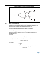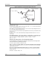
1
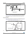
RHF1401 User manual CMref = 0.5 V and CMref + 0.2 V = 0.7 V By definition, the limitation on the lower side is -0.2 V The limitation of Vin on the upper side is given by this equation: Vinmax + Vbias ------------------------------------------------- 0.7V 2 So Vinmax = 0.9 V. Finally – 0.2V Vin 0.9V that gives: 5734 Output Code (decimal) 11468 Here, the full scale is not usable but a limited range only. 3.2.3 INCM biasing As previously discussed, INCM is an input/output that’s used to bias the internal OTA amplifiers of the RHF1401. So INCM can be any value from Table 4. However, depending on the INCM value, the performance can change slightly. For RHF1401 and for INCM from 0.4 V to 1 V, no impact on performances can be observed. For INCM from 0.2 V to 0.4 V and 1 V to 1.1 V, it’s possible to have, under boundary conditions, a typical loss of one bit of ENOB. So, if you have the choice, keep the value of INCM in the range 0.4 V to 1 V. 3.3 Output code vs. analog input and mode usage Whatever the configuration chosen (differential or single-ended), the two following equations are always true for RHF1401: The full scale of the analog input is defined by: Full scale = 2 x (Vrefp - Vrefm) The output code is defined also as: Output code = f(Vin - Vinb) vs. Full scale Finally we got for DFSB = 1: 3FFF Vin – VinB - + 1FFF Output code (14 bits) = -----------------------------------------------------2 Vrefp – Vrefm and for DFSB = 0: 3FFF Vin – VinB - + 1FFF + 2000 Output code (14 bits) = -----------------------------------------------------2 Vrefp – Vrefm DocID13317 Rev 9 21/38 38