1
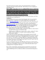
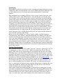
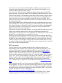
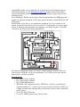
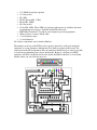
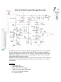
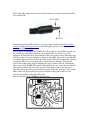
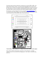
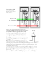
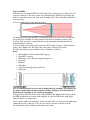
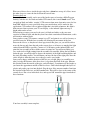
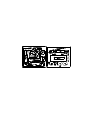
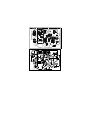
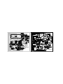
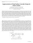
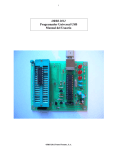
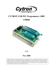
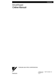
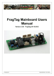
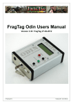
Xenon’s MilesTag
Tutorial
First Edition
www.LaserTagParts.com
Note: In this tutorial, I’ll assume you have good general knowledge on electronics,
soldering, printed circuit boards and the like – but I’ll still try to cover everything in as
much detail as I can.
DISCLAIMER: I AM NOT IN ANY WAY RESPONSIBLE FOR ANY DAMAGES
OR INJURY INFLICTED AS A RESULT, OR REGUARDING TO
INFORMATION PROVIDED WITHIN THIS DOCUMENT. USE THIS AT YOUR
OWN RISK. I HAVE MADE THIS DOCUMENT AS ACCURATE AS POSSIBLE
TO MY OWN KNOWLEDGE AND EXPERIENCE, BUT ERRORS MAY STILL
EXIST WITHIN THE FOLLOWING INFORMATION.
Finding where to start working on a MilesTag gun is pretty hard, but I guess you’ll have
to source all of your components first.
Components
In the beginning I tried to get by using my local electronics shop, but soon found that
they supplied close to nothing that was needed for MilesTag at a reasonable price.
Mouser (http://www.mouser.com) was my first alternative; they ship to most places for a
low price (or in some cases, free) and have just about anything you could want for your
MilesTag board and PIC programmer. Another very good site worth mentioning is
http://www.futurlec.com – they are another international electronics site, and stock most
parts, but not all. I’ve ordered my entire ISD programmer (plus many ISD chips) from
them, and a few spare parts such as capacitors, MOSFETs, resistors and PICs.
Just as a brief summary, this is where I got most of my parts from:
• PIC Programmer, blank PCB, etchant, soldering iron, multimeter, infrared camera
and other common tools: Local electronics shops
• ISD Programmer, NiMH batteries, battery holders, speakers, switches, IC sockets,
LED’s, resistors, capacitors, and smaller common components: Futurlec
• MilesTag parts: Mouser
I know it may seem a bit hectic ordering from so many suppliers, but you’d be hard
pressed to find one place that stocks everything for a reasonable price, that you can easily
order from in bulk. For example, Mouser stock a HUGE range of components, so when
you search for “4.7uF capacitor” you can get 2000+ hits, leaving you wondering which
one to get, as they are all so specialized. This is where places like Futurlec come in; they
stock standard components for dirt cheap (usually around 15 cents for a pack of 10), and
seem to be a rather exclusive seller of ISDs.
As I take you though all of the parts of the MilesTag creation process, I’ll refer to these
companies as to how appropriate they are to order relative components from, with regards
to the certain part I am talking of. I hope I can save you the many many hours I spent
searching the net for components in this way.
First, I’ll take you through the general ideas and pieces of hardware you will need to
make before you can get started on the MilesTag itself. These are all essential to the
creation of MilesTag, and I’ve used the most effective and economical circuit plans for
you.
PCB Etching
PCB etching is probably one of the most time consuming procedures during the creation
of MilesTag. There are many different ways to etch a PCB, and different chemicals to do
it. I will outline one way to do it (the toner transfer method) that I’ve found most
effective.
The conventional way of etching a PCB was to buy a special ‘etch resistant’ pen, some
etching solution, and a ‘blank’ PCB, which is a sheet of fibreglass coated with a thin
layer of copper. You would draw the tracks you didn’t want etched (or eroded from the
board by the etchant) onto the blank printed circuit board, and then dip it into an etchant
for about 30 minutes to remove all of the copper you didn’t need, and once completed,
where you had drawn, copper traces were left behind. This process was not only time
consuming (especially for numerous boards), but made it almost impossible to create the
small and delicate tracks required for most boards; especially in the PIC programmer.
After many days of failed boards using this method (and a few other methods), I found a
web site that explained if you used the right type of photo paper in a laser printer, you
could print the image of a circuit board, and, by reapplying heat with an iron, could
transfer the tracks on it to a PCB, which would protect the copper from the etchant and
leave you with a perfectly etched board.
Before you start, the etchant I use is Ferric Chloride, which is available from most
electronics shops. This etchant is a thick black liquid that you submerge a PCB in once
you have laid down an image of the tracks you want to be preserved with a protective
layer. After about 30 minutes, all of the exposed copper is ‘eaten’ away, and you are left
with only the tracks you had marked. The protective layer (in our case, laser printer
toner) can then be removed after by gentle scrubbing with steel wool. It is worthy to note
that Ferric Chloride can be reused many times at room temperature, whereas Ammonium
Persulphate (another common etchant) needs to be heated (and kept heated) and can only
be used once or twice.
The Toner Transfer Method:
First, you will need access to a laser printer, and some ‘semi-gloss’ photo paper. You can
use photo paper as it has a layer of ‘clay’, which laser printer toner doesn’t stick very
well to. This can be used to your advantage as you can later iron the toner onto a blank
PCB. Paper type is very important; if you use the wrong type of photo paper, at worst it
can melt to the insides of a laser printer and destroy it, or the toner might not stick to the
PCB after ironing. If you cannot get either suitable paper or access to a laser printer, there
are businesses out there that will manufacture PCBs for you, such as ExpressPCB.
Before you use any photo paper in a laser printer, get your iron, and turn it on to full. Run
the hot iron over the glossy side of the photo paper and be sure none of it melts – if it
does, it will be unsuitable for a laser printer. If it doesn’t, and withstands the hot iron,
there’s a good chance it’ll be fine. I have used many different types of paper for the toner
transfer, but found that “HP Everyday Photo Paper” does the job very well. This can
usually be found at your local office supply store.
Once you have found some photo paper that is relatively heat resistant, place it in your
laser printer so that the glossy side will be printed onto, and print the PCB design to the
paper. You should then cut the image out, and cut a piece of blank PCB to the same size.
Clean this PCB with steel wool, so that it turns nice and shiny (using water is fine, as
long as it is dried after); there will be millions of tiny little scratches over it from this –
they don’t matter. Once you have finished lightly scrubbing it, get a paper towel and
clean the board with methylated spirits. Keep wiping the board clean until there is no
residue left on the paper towel after wiping.
Now, turn your iron onto the hottest setting, and align the photo paper with the PCB
image face down, on top of the clean PCB. You should place the PCB on a piece of flat
wood as it will provide a solid and heat resistant surface for the ironing. Once the iron is
hot, press down onto the top of the carefully placed paper with it for about 20 seconds.
Once you lift the iron, the paper should have stuck to the surface of the PCB. Keep
ironing over the entire surface of the board for about 2 or 3 minutes, making sure to heat
the entire board evenly.
Once you have finished this, carefully pick the board up, not allowing any paper to curl
from the PCB surface, and place it (with the paper still attached) into some warm water.
After about 15 minutes, you should be able to see the water working its way through the
paper. After 25 minutes, you can slowly and carefully peel the paper from the PCB,
which should leave the toner tracks behind.
If the toner tracks have peeled with the paper, you can clean the board once more to rid it
of the rest of the tracks with steel wool, and try again. Different papers have very
different effects; a paper that works in my printer may not work for yours, and be sure the
blank PCB is very clean before you try to transfer the toner.
If you have successfully transferred all of the toner, you can then submerge the PCB in
Ferric Chloride for about 30 minutes to remove all of the copper around the tracks. While
the PCB is in the etching solution, you should agitate it every now and again. Once the
etching is complete, you can lightly scrub the toner from the remaining tracks to reveal
the copper. All you need to do now is drill the holes for the components with a 1mm drill
piece, and you’ll have finished the PCB.
PIC Programming
I spent a good two weeks searching through tech docs on the net trying to get an
understanding of PICs and how they work with regard to MilesTag. Basically, all you
really need to know (and all I really gained from this time spent) is that the original
program for these PICs is written in ‘PIC Basic’ in a compiler called PICBasic Pro,
which is worth about $US250. If you want to modify the source code in any way, you
need to buy this program to recompile it after you’ve made the changes. No, it’s not easy
to get a ‘free’ version, and the language is particular to the compiler, so no third party
cheaper compilers will be able to modify the MilesTag source code. But for standard use
(like our use) you won’t need any modification at all, you can just use the code the
creator of MilesTag has compiled for you; the HEX file from the MilesTag 4.xx home
page.
Once you obtain your PIC, you’ll need to transfer this HEX file to it; this is done using a
PIC programmer. The most versatile and economical programmer I’ve found on the net
was the ‘P16 Pro’. It requires a minimal amount of components, and works straight off
the parallel port on your computer, through a program called EPIC. EPIC is a great little
program, and the Beta is freely available from
http://www.melabs.com/downloads/E246BETA.ZIP .
As far as I’ve heard, this program has problems running on Windows XP, as XP has
parallel port protection, so I’ve always used Windows 98 on the machine I use to
program PICs. If this isn’t an option for you (you don’t have an old computer that you
could install Windows 98 on), MicroEngineering Labs might be able provide further
support regarding this problem in Windows XP, but I’d strongly suggest using an older
operating system.
As for building the P16 Pro, the last pages of this document include the PCB image and a
graphic of component placement. Use the toner transfer method to etch the PCB, and drill
out the holes.
In the P16 Pro design, there is one superfluous component; G1. It is a rectifier for AC
current, and doesn’t need to be used, as you can use 2 x 9volt batteries as a power supply.
Instead of obtaining and placing this rare component, you should just place 2 wire links
as shown in red on the topside of the finished PCB:
Note that this PCB image is made as if you are ‘looking through’ the PCB. If you ever
want to create a PCB, this is how you should make it, as it allows for the toner transfer
method, and is considered standard.
Component List:
• IC1: 78L05 voltage regulator
• IC2: 78L08 voltage regulator
• IC3: 74LS05 buffer/inverter
• TEXTOOL: This component can be a ‘ZIF Socket’, which is a special kind of
socket for holding IC’s – it allows for very easy insertion and removal of PICs. It
is highly recommended, although, they are a bit more expensive than a normal 20
cent IC socket.
• T1 and T2: BC557 Transistor
• C1 and C2: 100nF capacitor (type doesn’t matter)
C3: 220uF electrolytic capacitor
C4: Not needed
R1: 1KΩ
R2, R3, R4 and R5: 4.7KΩ
R6 and R7: 10KΩ
R8: Not needed
D1 and D2: LEDs. These LEDs let you know when power is available and when
programming in is progress. Standard 5mm LEDs work well.
• DB25 Male Connector: To connect your computer up to the programmer
• 50cm of 6 core (or more) ribbon cable
• 2 x 9volt battery snaps
• 2 x 9volt batteries
All of these components can be found at Futurlec.
•
•
•
•
•
•
•
The numbers at the top of the PCB are the respective pins those solder pads should be
connected to at your computer, although not all of them are printed on the board. The
cable between the PIC programmer and your computer should be kept as short as possible
to avoid any programming errors due to interference. Below is a diagram of a DB25
connector, and how it should be wired to the board (the DB25 connector is viewed from
behind, where you can solder the wires to):
Once you have placed and soldered all components, including the DB25 connector, you
should get both the 9volt battery snaps you bought, and connect them together in
SERIES. This will provide 18volts to the circuit, which is sufficient to program the PIC.
Connect the positive lead from the two batteries to the ‘+’ solder pad on the PCB.
Connect the negative lead from the two batteries to the ‘-‘ solder pad on the PCB.
Congratulations! You have just finished the PIC programmer. You should be able to
place a PIC in the ZIF socket, plug the batteries in, and plug it into your computer’s
parallel port. Now, start EPICWIN.EXE. If you get a message saying ‘PIC Programmer
Not Found!’, check all connections and power to the programmer. The power LED
should be on. If the program starts without errors, you can click File – Open to open the
HEX file. Once you have opened the HEX file, click the ‘Program’ button. EPIC will
now write to, and verify your PIC!
If any problems come up in making the PIC Programmer, or with the programming itself,
do not hesitate contact me at Laserforums.com.
ISD Programmer
The ISD chip in the MilesTag design is to generate all of the sounds associated with the
weapon and its functions. These sounds can be any .WAV format sound you have on
your computer. It is important to know that there are certain sounds needed, and in a
particular order:
1
Main Firing Sound (Used for Semi and Full Auto)
2
Chamber Empty
3
Reload Initiate (when reload button pressed)
4
Reload Complete (after reload delay time)
5
Beep (Key press)
6
Near Miss
7
Hit
8
Dead / Tagged Out
9
System Power-up (when gun is turned on)
10
Receive Data Failed (cloning)
11
Receive Data Good (cloning)
Each of these sounds are required, if you feel that you don’t want one, it should be
replaced by a brief period of silence.
Once you have got all of your sounds organised, you should store them in a folder with
their respective number in the file name, to make things easier for later when you
program the ISD.
Making the ISD programmer is very similar to making the PIC Programmer, but its
functionality is slightly different; it uses an analogue input to record the sounds from your
computer, so not only will it have a DB25 parallel port connecter, but it will also have a
3.5mm audio plug to plug into your sound card output.
Below is the schematic of the ISD recorder; it is based on the K64 programmer available
in kit form from many electronics outlets, but for simplicity and to facilitate its new
functionality (the computer interface), I’ll tell you how to make it yourself.
The PCB for this circuit is relatively simple, but you should note that some components
have been mounted underneath the socket of the ISD. These components should be
soldered to the underside of the board. This is done so ensure maximum stability of the
ISD during recording, and to save space on the PCB layout. There is also a wire link
underneath the ISD to bridge two tracks.
Note that the PCB for the ISD programmer (located on the last pages of this document) is
still being revised, and will be updated as problems are fixed (if there are any). This is
revision 1.00.
Components
• 9volt battery clip
• Male DB25 Connector
• Male 3.5mm Mono Audio Jack
• 50cm of 6 core (or more) ribbon cable
• C1, C2, C4, C6: 0.1uF Capacitor
• C3: 100uF Capacitor
C7: 1uF Capacitor
C8: 4.7uF Capacitor
Q1, Q2: BC547 Transistor
Q3: BC557 Transistor
Q4: 2N7000 Transistor
LED 1, LED2: Standard 5mm LEDs
7805: LM7805 Voltage Regulator
R1: 470KΩ
R2: 4.7KΩ
R3, R4: 22KΩ
R5, R6: 680Ω
R9: 10KΩ
R10, R11: 100KΩ
R12: 1KΩ
LNK: Wire Link
Small hobby speaker
Single Pole, Double Throw Switch. This switch is positioned on the board next to
the ‘Play’ and ‘Rec’ labels. It is switched to the desired position before operation.
• ISD: In place of the ISD, it is recommended you use another ZIF Socket, as it
makes insertion and removal much easier. If you don’t want to use a ZIF Socket,
you should use a normal IC socket.
• Power: For the power supply you should use a 9volt battery; be sure it is
connected with the right polarity when you solder it to the board.
All of these components are available from Futurlec.
Once again, the DB25 plug is viewed from behind, where you would solder the wires to
the plug itself.
•
•
•
•
•
•
•
•
•
•
•
•
•
•
•
•
•
The 3.5mm audio plug should be wired so these contacts are connected to their labelled
pads on the PCB:
RCA GND
RCA +ve
Programming with the ISD recorder is very easy; simply download the ISD recording
software and the parallel port drivers from the FragTag web site. You may also need the
VisualBasic 6 Runtime files.
Once you have downloaded and installed all of the programs, plug the ISD recorder into
the parallel port and speaker output of your computer. Run isd_record.exe. In this
program you should add all of your sound files that you prepared earlier. Remember that
order does matter. Set your computer’s volume to about 60%, then click record. The ISD
recording program will now record each sound onto the ISD in the programmer. Once the
recording is finished, you can unplug the recorder from the computer. You can now
preview the sounds on the chip by changing the toggle switch to ‘PLAY’ and shorting
pins 1 and 3 of the 2N7000. The sounds should play one by one, each time you short the
transistor. If you find that part of the sound has been clipped at the start, you can rerecord the chip with a delay specified in the program. Generally speaking, a delay of 20 –
50ms works well. If the sound is too quiet or distorted, change the volume of your
computer accordingly, and re-record the chip.
Pins one and three of the 2N7000 are shown below:
MilesTag
Now that you have finished the ISD programmer and PIC programmer, and programmed
your PICs and ISDs, you are ready to construct the MilesTag boards. These boards are
probably simpler to make than the PIC programmer and the ISD programmer, but might
take a little longer as soldering the wires for connections to the LCD, power, speaker, IR
LED, muzzle flash, trigger etc. is somewhat time consuming. For this reason, I’ve tried to
allow for ease of construction in my board design.
Components; (all resistors are quarter watt, unless otherwise specified).
• ISD25XX Sound Chip
• 4 x 4.7uF Tantalum capacitors
• 7 x 10KΩ Resistors
• 2 x 51Ω Resistors
• 10Ω 1 Watt Resistor
• 10Ω Resistor
• 4 x 100Ω Resistor
• 100Ω 1 Watt Resistor
• 100uF Electrolytic capacitor
• 10uF Electrolytic capacitor
• 5 x 0.1uF Ceramic capacitor
• 0.047uF Monolithic capacitor
• 220uF Electrolytic capacitor (polarised)
• LM386 Amplifier
• 100K Logarithmic variable resistor
• 2 x 1MΩ Resistors
• 7805 Voltage regulator
• 20KΩ Linear variable resistor
• PIC 16F648A
• 2 x MOSFETS or HEXFETs; any N-Channel, Logic-level, less than .1ohms RDSon
(on-resistance) MOSFET or HEXFET should be fine.
• 3 x TSOP4840 Infrared Sensors
• 2 x TSAL6100 Infrared LED’s (It’s good to have a spare)
• 1 x Ultrabright LED For muzzle flash
• 2 x Microswitches
• Keyswitch or removable switch for configuration mode
• 1 x Standard LED for hit LED
• 1 x 8x2 character LCD display (with or without backlight, it’s up to you)
• 1 x Large hobby speaker (about 4 inch diameter is good)
• 1.5 meters of ~14 core ribbon cable for connecting everything together
• 18 pin IC socket
• 1 x small pushbutton for modes
• 28 pin IC socket
Most of the more common components are available from Futurlec, however, you will
need to order the LCD screens, infrared LEDs, TSOP4840s, (and possibly the 16F648A if
you want to get a good price) from Mouser.
You should solder all of the components onto the board, except the PIC and ISD – they
will be placed in the IC sockets, as it prevents them being damaged by excessive heat
from the solder, and allows for removal if program modifications are needed. Once all of
the components are in place according to the component placement graphic, you should
connect the LCD screen up to the pads on the board. It should be connected as follows:
Note that these are the pin outputs for mouser part number 668-C-S0802XRGNN, they
are standard, but the outputs still may vary from LCD to LCD. The LCD screen is being
viewed from the front, and the PCB is being viewed from the top.
Note that Pins 1 and 5 both go to –ve, and pin 3 goes to the variable resistor output.
Once you have finished soldering the components to the main board, you should
complete at least one sensor board for testing purposes, and connect it to the MilesTag
board also.
The ‘rails’ for the TSOPs
can be linked to many
TSOP boards in parallel as
in this diagram:
To pin 6 on PIC
To -ve pad on PCB
To +5volt pad on PCB
After all of the components and LCD screen have been
connected, you should also connect the speaker, microswitches
for reload and fire, the mode push button, the key switch
(turned on), the muzzle flash LED (with the negative side
connected to the Muzzle LED pad, and the positive side
connected to a 5volt pad on the left of the board) and the
sensors [Locations for the above switches and sensors are on
the next page].
Once done, for testing purposes, you can now connect a 9volt
battery up to the pads marked + and – in the MilesTag board
graphic above.
The variable resistor for the LCD display is likely to be set
either too high or too low, so once you connect power, you can
turn it until you get a clear picture on the LCD display. It should have readout of health,
ammo, etc. If you are not seeing any picture on the screen, check all connections, and be
sure the power supply is reliable.
Once the LCD display is working, you can navigate through the configuration menus as
per the MilesTag user’s manual. Once you have completed the configuration, test fire the
gun; you should be able to see the muzzle flash and hear the sound effects you
programmed to the ISD.
If the MilesTag gun has worked, Congratulations! All you need to do now is complete it
by connecting the infrared LED to the IR LED pad (just above the muzzle flash pad) on
the negative side of the LED, and the positive side to the hole next to the battery input,
and by connecting the hit led to the HIT pad on the negative side, with the positive
connected to a +5volt pad.
Batteries
A lot has been said about batteries and power supplies with regards to MilesTag, but
generally speaking, these conclusions have been drawn:
• NiMH batteries, although they may be a bit more expensive than NiCad batteries,
they are much lighter for a given capacity, and therefore are used more often.
• You can run a MilesTag gun off a 7.2volt battery pack, but it’s likely you would
get better stability from an 8.4volt or a 9.4volt pack. I’ve used a 7.2volt pack with
no problems, though.
• If you are buying a battery pack new, it’s a wise choice to buy NiMH
I’ve made my battery packs out of AA NiMH batteries from
Futurlec. They also sell 6 cell plastic battery holders, which
provide a convenient way to mount these batteries, and with
the battery snap connection typical of a 9volt battery, they
allow for easy insertion and removal for recharging.
There are many rechargers available for both NiMH and NiCad
batteries, but when buying, be sure that the charger you get is a
Peak Charger or a Smart Charger. These monitor the battery’s
voltage throughout the charge, and stop charging after the pack
is full. This prevents damage to the batteries through overcharging or overheating.
If you feel up to making a home made peak detecting charger, schematics and a PCB
layout for a very good one is available at
http://homepages.paradise.net.nz/bhabbott/charger.html .
Lens Assemblies
Without a lens, an infrared LED will not be able to hit a player any more than a few feet
away on a sunny day. The lens system stops the light from a LED from spreading, and
makes a concentrated spot, that, with good focusing, will be able to hit players hundreds
of meters away.
A lens assembly works as this diagram shows:
As the light spreads from the LED, it is diffracted by the lens to travel in a straight line.
In a perfect lens assembly, the focused beam would travel to infinity with the same
intensity. This, of course, is impossible due to our atmosphere and imperfections in
manufacturing of each part.
A lens assembly can easily be made form some PVC piping. I suggest ~55mm diameter
piping, and a 50mm lens. This allows for a long range, and ease of creation.
A simple and effective lens assembly can be constructed as follows:
Parts:
• About 40cm of 55mm diameter PVC piping
• 55mm PVC end-cap
• 50mm lens (easily found in magnifying glasses)
• 5mm drill
• Hacksaw
• Superglue
• 4 pop rivets and appropriate drill size
• Pop riveter
It is very important that in every step in making the lens assembly, you align or cut
the parts at right angles to their respective surface. Failing to do so will result in a
beam that isn’t straight, or can’t be focused properly.
Using the 5mm drill, drill a hole for the infrared LED in the centre of the end-cap. Push
the LED into the hole and secure with superglue, be sure the LED makes right angles
with the surface it’s mounted on.
Cut 2 sections off the end of the pipe, about 3cm wide. The use of a miter box might help
cutting these at 90° to the pipe. Cut a slot out of these sections so that they can be
inserted into the inside of the pipe and slide up and down.
Place one of these sleeves inside the pipe and place a clean lens on top of it. Next, insert
the other sleeve to secure the lens between the two off-cuts.
Focusing the Lens
Focusing the lens assembly can be one of the hardest parts of creating a MilesTag gun.
Luckily, with the use of a black and white CCD camera, this is made much easier. You
can pick up black and white ‘security’ CCD cameras from most electronics stores for less
than $100, which is a pretty good deal when you consider how well it works for this
application. CCD cameras can see infrared light that is invisible to humans; this light is
then converted into a picture your TV can display, so the infrared light comes up as
bright white on the screen.
When buying a camera, you need to be sure it is black and white, as they are most
sensitive to infrared light, and that they don’t have their own infrared illumination, as this
will interfere with our work.
Once you have your CCD camera, connect it to a TV and point it at a wall as far away as
possible from you. With the lens assembly still allowing for movement of the lens
between the sleeves, as they haven’t been pop-riveted into place yet, you will be able to
move the lens up and down the tube to the correct place so it focuses as much of the light
emitted from the LED as possible. Connect a 1.5volt battery to the infrared LED, and
point the lens assembly at the wall the camera is trained on. You will most likely get a
very weak circle of light coming from the assembly. By carefully sliding the lens further
down the pipe, you will be able to observe the intensity of the light becoming higher, and
the circle becoming smaller. You will know you have the lens in the right place once the
circle of light is about the same size as the pipe, and is very bright.
Once you are happy with the location of the lens, use a depth gauge (or carefully use a
ruler) to judge the distance of the first sleeve’s edge from the front of the pipe. Measure
this distance down the outside of the pipe, and add about 1.5 centimeters to the length, so
you locate the approximate middle of the first sleeve. Drill a hole through both layers of
plastic, and push a pop-rivet into the hole. Pop the rivet. Now measure another 3cm from
the location of the first rivet, and drill another hole. This will be close to the center of the
second sleeve. Put a rivet in this hole also, and repeat 180° around the pipe from both of
these locations.
Your lens assembly is now complete.
Tips on Building a Stock
Most stocks are relatively simple to engineer out of wood and aluminium. If you find a
picture of a gun you would like to build, using a painting program you can make an
outline, and print a scale silhouette over a few pages which you can work off. Finding the
right type of wood can often be hard, but I’ve found that layering thick plywood, and
gluing them together makes for a sturdy and thick piece of wood that is easy to carve.
It is easiest of you don’t make the entire gun out of wood though, as aluminium
channelling will allow you to have a very accurate spline to mount the lens assembly and
any sights to. Wood often bends slightly to one side, ruining any chance of having a long
range weapon, and is much harder to make precision holes in than metal, as the wood
usually gives way slightly to any screws. It is often best to have a wood handle and butt,
and an aluminium channel for mounting the barrel, sights and lens assembly.
Be sure to leave more than enough room for all of the electronics, including the batteries,
speaker, switches and LCD display.
Remember that a 1mm error in sights or lens assembly alignment on the gun will end up
as many meters difference over some distance. Take your time making the casings.
Conclusion
That’s about it! I hope I’ve covered everything in this document you needed to know.
This is Revision 1.30. You should be aware that there might be errors in some of the
electronics, but I’ve done my best to design and reproduce them for you accurately (these
are the same plans I’m using, so I have put a lot of time into them).
I would like to hear any problems regarding the design or functionality, and would be
glad if you check through the designs BEFORE you make it, to be sure you aren’t
wasting your time or money. This includes the component lists, PCB layouts, polarity of
components and any other conceivable errors. You should notify me of these problems by
messaging me at Laserforums.com so I can correct and improve designs for later
revisions. I have prototyped each of these boards, and they have all worked, so it is likely
that if your project hasn’t worked, you may have made an error.
A note on printing PCB images: Be sure scaling is disabled in the print options window
when you are going to print PCB images from this document, as they will be the incorrect
size if your printing program changes their dimensions in any way, and will cause many
components to not fit properly.
Any successes in building your MilesTag set would be gladly received also.
Thanks,
Xenon
42
+PS
redroceR DSI
01.1v noneX yB BCP
moc.surstiK morf 46K no desaB
-PS
xx.4 gaTseliM
noneX yB BCP
03.1v
moc.straPgaTresaL