1
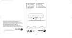
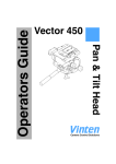
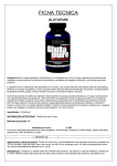
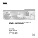
FCS-16
Fusion Control System
Operators Guide
V4035-4980
Robotic Camera Control Systems
Operators Guide
Vinten Radamec
FCS-16 Fusion Control System
Publication Part No. V4035-4980
Issue 1 (April 2008)
Original Instructions
Copyright © Vitec Group plc 2008
All rights reserved throughout the world. No part of this document may be stored in a retrieval system. transmitted, copied or reproduced
in any way including, but not limited to, photocopy, photograph, magnetic or other record without the prior agreement and permission in
writing of Vitec Group plc.
Vinten Radamec® and Vinten® are registered trademarks of Vitec Group plc.
Preface
Thank you for buying the
Vinten Radamec Fusion Control System.
We want you to get the most from your new Fusion Control System (FCS), and therefore encourage you to
read this operators guide to familiarize yourself with its many features. It also covers essential health and safety
information and a section on maintenance that will ensure you keep your new product in perfect condition.
Features and benefits of your new Fusion Control System
The new control system provides a compact control solution and is backward compatible with established products from Autocam and Radamec. The system comes complete with a joystick panel and 10.4" touch screen
for simple shot recall and storage.
• Shot Storage of all axes in easy one-touch operation
• Compact, desk mountable
• Easy to use
• Can be networked allowing operational flexibility
• Controls up to 16 devices
• Touch screen control
Once again, thank you for choosing the Vinten Radamec Fusion Control
System.
We are confident it will give you many years of reliable performance.
3
4
Safety - Read This First
Understanding these instructions
English
The original instructions presented in this operators guide were written in English, and subsequently
translated into other languages. If you are unable to understand these instructions, contact Vinten
Radamec or your distributor to obtain a translation of the original instructions (EU Countries).
БЪЛГАРСКИ
Оригиналните инструкции, представени в настоящото ръководство на производителя, бяха
написани на английски език, а след това - преведени на други езици. Ако не разбирате тези
езици, свържете се с Vinten Radamec или с Вашия дистрибутор, за да получите оригиналните
инструкции (за страните от Европейския съюз).
Česky
Pokyny uvedené v této operátorské příručce byly původně napsány anglicky a následně byly
přelo_eny do ostatních jazyků. Nerozumíte-li těmto pokynům, kontaktujte společnost Vinten Radamec
nebo svého distributora, abyste získali překlad originálních pokynů (členské státy EU).
Danish
De originale instruktioner, der præsenteres i denne betjeningsvejledning, er skrevet på engelsk og
derefter oversat til andre sprog. Hvis du ikke forstår disse instruktioner bedes du kontakte Vinten
Radamec eller vor forhandler for at få en oversættelse af de originale instruktioner (EU-lande).
Deutsch
Die Originalanleitung in diesem Bedienungshandbuch wurde auf Englisch verfasst und anschließend
in andere Sprachen übersetzt. Bei Verständnisproblemen in einer der übersetzten Sprachen
kontaktieren Sie bitte Vinten Radamec oder Ihren Fachhändler; dort erhalten Sie eine Übersetzung
der ursprünglichen Anleitung (EU-Staaten).
Eesti
Käesoleva kasutajajuhendi algtekst on koostatud inglise keeles ning seejärel tõlgitud teistesse
keeltesse. Kui juhend osutub teie jaoks arusaamatuks, võtke juhendi emakeelse tõlke hankimiseks
ühendust Vinten Radameci või kohaliku esindajaga (Euroopa Liidu riigid).
Ελληνικά
Οι αρχικές οδηγίες αυτού του οδηγού για το χειριστή συντάχθηκαν στα Αγγλικά και μεταφράστηκαν στη
συνέχεια σε άλλες γλώσσες. Εάν δυσκολεύεστε να καταλάβετε αυτές τις οδηγίες, επικοινωνήστε με τη
Vinten Radamec ή το διανομέα σας για να λάβετε μια μετάφραση των αρχικών οδηγιών (Χώρες ΕΕ).
Español
Las instrucciones originales que se indican en esta guía del operador se han redactado en inglés y
posteriormente se han traducido a otros idiomas. Si no entiende estas instrucciones, póngase en
contacto con Vinten Radamec o con su distribuidor para obtener una traducción de las instrucciones
originales (para países de la UE).
Français
Les instructions originales présentées dans ce guide d'utilisation ont été écrites en anglais puis
traduites dans d'autres langues. Si vous ne comprenez pas ces instructions, contactez Vinten
Radamec ou votre revendeur pour obtenir une traduction des instructions originales (pour les pays de
l'UE).
Gaeilge
Scríobhadh na treoracha bunaidh don treoirleabhar oibritheora seo as Béarla, agus aistríodh iad go
teangacha eile ina dhiaidh sin. Mura bhfuil tú in ann na treoracha seo a thuiscint, téigh i dteagmháil le
Vinten Radamec nó le do dháileoir, chun aistriúchán de na treoracha bunaidh a fháil (Tíortha an AE).
Italiano
Le istruzioni originali presentate in questa guida per l'operatore sono in lingua inglese e
successivamente tradotte nelle altre lingue. Qualora le istruzioni non fossero disponibili nella lingua
desiderata, potete contattare Vinten Radamec o il vostro distributore per ricevere la traduzione delle
istruzioni originali (Paesi UE).
5
Latviešu
Šajā operatora rokasgrāmatā iekļautie norādījumi sākotnēji tika sarakstīti angļu valodā un pēc tam
pārtulkoti citās valodās. Ja nesaprotat šos norādījumus svešvalodā, sazinieties ar Vinten Radamec vai
tirgotāju, lai saņemtu norādījumu tulkojumu (kādā no ES dalībvalstu valodām).
Lietuvių
Šiame operatoriaus vadove pristatomos pirminės instrukcijos parašytos anglų kalba ir vėliau išverstos
į kitas kalbas. Jei šių instrukcijų nesuprantate, susisiekite su „Vinten Radamec“ arba savo platintoju ir
gaukite pirminių instrukcijų vertimą (ES šalies kalba).
Magyar
A kezeloi útmutatóban található utasítások angol nyelven íródtak, és utólag fordították azokat más
nyelvekre. Ha nem érti ezen utasításokat, kérjük, vegye fel a kapcsolatot a Vinten Radamecnel vagy
a helyi képviselettel, és igényelje az eredeti utasítások fordítását (EU országok).
Malti
L-istruzzjonijiet originali ippreżentati f'din il-gwida ta' operaturi kienu miktuba bl-Ingliż, u
sussegwentement maqluba fl-lingwi ohra. Jekk ma tistax tifhem dawn l-istruzzjonijiet, ikkuntattja lil
Vinten Radamec jew id-distributur tieghek biex tikseb traduzzjoni ta' l-istruzzjonijiet originali (Pajjiżi ta'
UE).
Nederlands
De oorspronkelijke instructies in deze bedieningshandleiding zijn geschreven in het Engels en
vervolgens in andere talen vertaald. Als het onmogelijk is deze instructies te begrijpen, neemt u
contact op met Vinten Radamec of met uw distributeur om een vertaling te bemachtigen van de
oorspronkelijke instructies (EG-landen).
Polski
Oryginalne instrukcje zamieszczone w niniejszym podręczniku operatora zostały napisane w języku
angielskim, a następnie przetłumaczone na inne języki. Jeśli nie rozumieją Państwo tych instrukcji,
prosimy skontaktować się z siedzibą lub dystrybutorem Vinten Radamec, aby uzyskać tłumaczenie
oryginalnych instrukcji (kraje UE).
Português
As instruções originais apresentadas no guia do operador foram escritas em Inglês e traduzidas para
outros idiomas. Se não conseguir compreender estas instruções contacte a Vinten Radamec ou o seu
distribuidor para obter a tradução das instruções originais (Países da UE).
Română
Instrucţiunile originale prezentate în acest ghid pentru operatori au fost scrise în limba engleză, şi
traduse ulterior în alte limbi. În cazul în care nu înţelegeţi aceste instrucţiuni, contactaţi Vinten
Radamec sau distribuitorul dumneavoastră pentru a obţine o traducere a instrucţiunilor originale
(Ţările UE).
Slovensky
Pôvodné pokyny, uvedené v tomto návode na obsluhu, boli napísané v anglictine a následne
preložené do iných jazykov. Ak nerozumiete týmto pokynom, obrátte sa na spolocnost Vinten
Radamec alebo vášho distribútora, aby vám zaslal preklad originálnych pokynov (krajiny EÚ).
Slovenščina
Originalno besedilo teh navodil za uporabo je bilo napisano v angleščini in prevedeno v ostale jezike.
Če ne razumete teh navodil, se obrnite na podjetje Vinten Radamec ali lokalnega zastopnika, ki vam
bo posredoval originalna navodila (velja za dr_ave EU).
Suomi
Tähän käyttäjän oppaaseen sisältyvät ohjeet on kirjoitettu alun perin englanniksi ja käännetty sitten
muille kielille. Ellet ymmärrä näitä ohjeita, ota yhteyttä Vinten Radameciin tai jälleenmyyjään ja pyydä
alkuperäisten ohjeiden käännöstä (EU-maat).
Svenska
Instruktionerna i denna handbok skrevs ursprungligen på engelska och har sedan översatts till flera
språk. Om du inte förstår dessa instruktioner, kontakta Vinten Radamec eller din återförsäljare för en
ny översättning av originalinstruktionerna (EU-länder).
6
Warning symbols in this operators guide
Where there is a risk of personal injury or injury to others, comments appear highlighted by the
word WARNING!—supported by the warning triangle symbol.
Where there is a risk of damage to the product, associated equipment, process or surroundings,
comments appear highlighted by the word CAUTION!
Warning symbols on the product
On encountering the warning triangle
and open book symbols it is imperative
that you consult this operators guide
before using this product or attempting
any adjustment or repair.
Where there is a risk of electric shock,
comments appear supported by the
hazardous voltage warning triangle
symbol.
Regulatory information
WEEE directive
WEEE Directive 2002/96/EC mandates the treatment, recovery and recycling of electric and
electronic equipment. This product is subject to WEEE disposal regulations. Please visit
www.vinten.com/recycle for details.
European and International directives and standards
The following conformity certificates indicate the appropriate international directives and test standards to
which this product complies.
7
8
9
10
Contents
Page
Preface . . . . . . . . . . . . . . . . . . . . . . . . . . . . . . . . . . . . . . . . . . . . . . . . . . . . . . . . . . . . . . . . . . . . . . . . . . . . . . . 3
Safety - Read This First . . . . . . . . . . . . . . . . . . . . . . . . . . . . . . . . . . . . . . . . . . . . . . . . . . . . . . . . . . . . . . . . . 5
Regulatory information. . . . . . . . . . . . . . . . . . . . . . . . . . . . . . . . . . . . . . . . . . . . . . . . . . . . . . . . . . . . . . . . . . 7
Usage . . . . . . . . . . . . . . . . . . . . . . . . . . . . . . . . . . . . . . . . . . . . . . . . . . . . . . . . . . . . . . . . . . . . . . . . . . . . . . . 12
Technical data . . . . . . . . . . . . . . . . . . . . . . . . . . . . . . . . . . . . . . . . . . . . . . . . . . . . . . . . . . . . . . . . . . . . . . . . 13
Further information. . . . . . . . . . . . . . . . . . . . . . . . . . . . . . . . . . . . . . . . . . . . . . . . . . . . . . . . . . . . . . . . . . . . 13
Introduction . . . . . . . . . . . . . . . . . . . . . . . . . . . . . . . . . . . . . . . . . . . . . . . . . . . . . . . . . . . . . . . . . . . . . . . . . . 18
Operation
Create a user name and password . . . . . . . . . . . . . . . . . . . . . . . . . . . . . . . . . . . . . . . . . . . . . . . . . . . . 19
Use a studio datum . . . . . . . . . . . . . . . . . . . . . . . . . . . . . . . . . . . . . . . . . . . . . . . . . . . . . . . . . . . . . . . . 19
Run the VRC program . . . . . . . . . . . . . . . . . . . . . . . . . . . . . . . . . . . . . . . . . . . . . . . . . . . . . . . . . . . . . 22
Target camera units . . . . . . . . . . . . . . . . . . . . . . . . . . . . . . . . . . . . . . . . . . . . . . . . . . . . . . . . . . . . . . . 22
Configure the grid display . . . . . . . . . . . . . . . . . . . . . . . . . . . . . . . . . . . . . . . . . . . . . . . . . . . . . . . . . . . 23
Use a show . . . . . . . . . . . . . . . . . . . . . . . . . . . . . . . . . . . . . . . . . . . . . . . . . . . . . . . . . . . . . . . . . . . . . . 24
Select a camera . . . . . . . . . . . . . . . . . . . . . . . . . . . . . . . . . . . . . . . . . . . . . . . . . . . . . . . . . . . . . . . . . . 25
Store a shot . . . . . . . . . . . . . . . . . . . . . . . . . . . . . . . . . . . . . . . . . . . . . . . . . . . . . . . . . . . . . . . . . . . . . 27
Shot status colour codes. . . . . . . . . . . . . . . . . . . . . . . . . . . . . . . . . . . . . . . . . . . . . . . . . . . . . . . . . . . . 27
Fade to a shot . . . . . . . . . . . . . . . . . . . . . . . . . . . . . . . . . . . . . . . . . . . . . . . . . . . . . . . . . . . . . . . . . . . . 27
Cut to a shot . . . . . . . . . . . . . . . . . . . . . . . . . . . . . . . . . . . . . . . . . . . . . . . . . . . . . . . . . . . . . . . . . . . . . 28
Stop a Cut or Fade . . . . . . . . . . . . . . . . . . . . . . . . . . . . . . . . . . . . . . . . . . . . . . . . . . . . . . . . . . . . . . . . 28
Edit a shot . . . . . . . . . . . . . . . . . . . . . . . . . . . . . . . . . . . . . . . . . . . . . . . . . . . . . . . . . . . . . . . . . . . . . . . 28
Focus a shot function . . . . . . . . . . . . . . . . . . . . . . . . . . . . . . . . . . . . . . . . . . . . . . . . . . . . . . . . . . . . . . 29
Create a sequence of shots . . . . . . . . . . . . . . . . . . . . . . . . . . . . . . . . . . . . . . . . . . . . . . . . . . . . . . . . . 30
Enable a camera unit . . . . . . . . . . . . . . . . . . . . . . . . . . . . . . . . . . . . . . . . . . . . . . . . . . . . . . . . . . . . . . 30
Configure joystick settings . . . . . . . . . . . . . . . . . . . . . . . . . . . . . . . . . . . . . . . . . . . . . . . . . . . . . . . . . . 31
Configure panel options . . . . . . . . . . . . . . . . . . . . . . . . . . . . . . . . . . . . . . . . . . . . . . . . . . . . . . . . . . . . 32
Configure shot options . . . . . . . . . . . . . . . . . . . . . . . . . . . . . . . . . . . . . . . . . . . . . . . . . . . . . . . . . . . . . 33
Clear show . . . . . . . . . . . . . . . . . . . . . . . . . . . . . . . . . . . . . . . . . . . . . . . . . . . . . . . . . . . . . . . . . . . . . . 33
Exit the program . . . . . . . . . . . . . . . . . . . . . . . . . . . . . . . . . . . . . . . . . . . . . . . . . . . . . . . . . . . . . . . . . . 33
Servicing
General . . . . . . . . . . . . . . . . . . . . . . . . . . . . . . . . . . . . . . . . . . . . . . . . . . . . . . . . . . . . . . . . . . . . . . . . . 34
Cleaning . . . . . . . . . . . . . . . . . . . . . . . . . . . . . . . . . . . . . . . . . . . . . . . . . . . . . . . . . . . . . . . . . . . . . . . . 34
Routine checks . . . . . . . . . . . . . . . . . . . . . . . . . . . . . . . . . . . . . . . . . . . . . . . . . . . . . . . . . . . . . . . . . . . 34
Adjustments . . . . . . . . . . . . . . . . . . . . . . . . . . . . . . . . . . . . . . . . . . . . . . . . . . . . . . . . . . . . . . . . . . . . . 37
Parts list . . . . . . . . . . . . . . . . . . . . . . . . . . . . . . . . . . . . . . . . . . . . . . . . . . . . . . . . . . . . . . . . . . . . . . . . . . . . . 38
11
Illustrations
Page
Fig 1 FCS-16 Fusion Control System . . . . . . . . . . . . . . . . . . . . . . . . . . . . . . . . . . . . . . . . . . . . . . . . . . . . . . 14
Fig 3 Main Screen . . . . . . . . . . . . . . . . . . . . . . . . . . . . . . . . . . . . . . . . . . . . . . . . . . . . . . . . . . . . . . . . . . . . . 16
Fig 4 Configuration Screen . . . . . . . . . . . . . . . . . . . . . . . . . . . . . . . . . . . . . . . . . . . . . . . . . . . . . . . . . . . . . . 17
Fig 5 Fusion pedestal targeting . . . . . . . . . . . . . . . . . . . . . . . . . . . . . . . . . . . . . . . . . . . . . . . . . . . . . . . . . . . 20
Fig 6 SP-2000 pedestal targeting . . . . . . . . . . . . . . . . . . . . . . . . . . . . . . . . . . . . . . . . . . . . . . . . . . . . . . . . . 20
Fig 7 Fusion target origin . . . . . . . . . . . . . . . . . . . . . . . . . . . . . . . . . . . . . . . . . . . . . . . . . . . . . . . . . . . . . . . . 21
Fig 8 Grid size configuration screen . . . . . . . . . . . . . . . . . . . . . . . . . . . . . . . . . . . . . . . . . . . . . . . . . . . . . . . 23
Fig 9 Multiple target configuration . . . . . . . . . . . . . . . . . . . . . . . . . . . . . . . . . . . . . . . . . . . . . . . . . . . . . . . . . 36
Associated Publication
Vinten Radamec FCS-16 Fusion Control System
Technical Manual
Part No. V4035-4990
Usage
The FCS-16 Fusion Control System is designed for use in television studios to remotely control cameras, pan
and tilt heads and pedestals. The FCS-16 Fusion Control System is intended to be used by television camera
operators.
WARNING! 1. Do NOT attempt to use this product if you do not understand how to
operate it.
2. Do NOT use this product for any other purpose than that specified in the
Usage statement above.
3. This product has been designed for indoor use. Protect from water, moisture and dust.
4. Display prominent warning signs in studios, alerting personnel that
robotic equipment is present and may move without warning.
5. Ensure personnel remain a minimum of 1-metre (40 inches) clear of
robotic equipment during use.
6. Operators must familiarize themselves with the resulting working envelope of the robotic head including all ancillary equipment (lens, zoom and
focus controls, viewfinder, prompter etc.).
7. Only operate a pedestal remotely if you are able to see it, to avoid obstacles and collision hazards.
8. Maintenance beyond that detailed in this Operators Guide must be performed only by competent personnel in accordance with the procedures
laid down in the Technical Manual.
12
Technical data
Weight
FCS-16 Fusion Control System (including touch screen monitor and PC module)
7 kg (15.4 lb)
PC module
0.5 kg (1.1 lb)
Touch screen monitor (10.4”)
1.7 kg (3.3 lb)
Height
FCS-16 panel (including PC module and joysticks)
24.2 cm (9.5 in.)
Touch screen monitor (10.4”)
19.2 cm (7.5 in.)
Length
FCS-16 panel (including PC module and joysticks)
48.3 cm (19 in.)
Touch screen monitor (10.4”)
25 cm (9.84 in.)
Width
FCS-16 panel (including PC module and joysticks)
17.8 cm (7 in.)
Touch screen monitor (10.4”)
3.8 cm (1.5 in.)
Maximum power consumption
70 W
Input voltage
Autoranging 90-264V AC 47/63 Hz
System fuse
5 Amps
Operating temperature
0 - 40°C (32 - 104°F)
User ports
4 x top mounted USB 2.0
2 x bottom mounted USB 2.0
Keyboard
USB
Mouse
USB
Control capacity
16 camera units
Further information
For further information regarding this Lightweight control panel, please contact Vinten Radamec (see back cover), or visit our website.
For full details on maintenance and spare parts, please refer to the Vinten Radamec FCS-16 Fusion Control
System Technical Manual and Illustrated Parts List - Publication Part No. V4035-4990. This is obtainable from
Vinten Radamec. For information on-line, visit our website at
www.vintenradamec.com
13
(17)
(18)
(1)
(2)
(16)
(15)
(3)
(4)
(14)
(5)
(13)
(12)
(11)
(10)
(9)
(8)
(7)
(6)
Fig 1 FCS-16 Fusion Control System
(1)
Touch screen
(2)
On air (Tally) indicators
(3)
Pan follow button
(4)
Joystick enable button
(5)
Bumper disable button
(6)
Target disable button
(7)
Panel disable button
(8)
Backup link button
(9)
Camera zoom/pan and tilt head control joystick
(10)
Camera preview buttons
(11)
Cut to shot button
(12)
Fade to shot button
(13)
Stop button
(14)
Fade time control
(15)
Camera focus control
(16)
Pedestal control joystick
(17)
Power switch
(18)
USB ports
14
(19)
(20)
(21)
(22)
Fig 2 Lightweight Control Panel, underside
(19)
PC module
(20)
USB ports
(21)
Power input socket
(22)
System fuse
15
(38)
(23)
(24)
(37)
(36)
(35)
(34)
(33)
(32)
(31)
(30)
(29)
(28)
(27)
(26)
(25)
Fig 3 Main Screen
(23)
Grid column header
(24)
Empty shot location
(25)
Options menu button
(26)
Page down button
(27)
Page up button
(28)
Sequence button
(29)
Focus shot button
(30)
Store shot button
(31)
Fade to shot button
(32)
Cut to shot button
(33)
Stop button
(34)
Edit shot button
(35)
Menu button
(36)
Camera select button
(37)
Grid row header
(38)
Show title
16
(54)
(55)
(39)
(40)
(41)
(53)
(42)
(52)
(43)
(51)
(44)
(50)
(49)
(48)
(47)
(46)
(45)
Fig 4 Configuration Screen
(39)
Toggle zoom control direction
(40)
Toggle focus control direction
(41)
Toggle elevation control direction
(42)
Toggle always enable drive
(43)
Toggle always disable IR
(44)
Toggle always disable bumpers
(45)
Toggle require shot time
(46)
Toggle display shot time
(47)
Toggle require shot name
(48)
Return to main screen button
(49)
Toggle display shot name
(50)
Toggle always override
(51)
Toggle double button push
(52)
Toggle pan control direction
(53)
Toggle tilt control direction
(54)
Grid size button
(55)
Toggle display headers
17
Introduction
The FCS-16 Fusion Control System enables an operator to remotely control cameras, pedestals, and pan and
tilt heads. Used within a Fusion system configuration, the FCS-16 is compatible with current and many discontinued Radamec and AutoCam robotic products. Older system configurations will need updating to ensure
compatibility—please contact Vinten Radamec or your local Vinten Radamec distributor for information (contact details are shown on the rear cover).
Touch screen control system
(Fig 3)
All Lightweight Control Panel displays are touch screen enabled, allowing options to be selected by touching
on-screen graphics with a finger. Alternatively, it is possible to select on-screen options using the left mouse
button. The touch screen user interface is identical to the VRC system, and closely resembles the Radamec
TCPi system.
Grid display
A grid display (24) is used to identify individual stored shots. Each shot has a unique address, derived from its
position in the grid display (24) relative to the labelled columns (23) (alpha values) and rows (37) (numeric values). In practice, this grid visually allows shots to be stored in a series of ‘boxes’ (24) over multiple pages.
Camera selection and status bar
The FCS-16 can control up to 16 camera units. Buttons to select all connected camera units (36) can be found
below the grid display (24). Once selected, the camera unit can be controlled using the joystick control panel.
These buttons also indicate the status of the camera units using the following colour codes:
Green - Camera currently selected and controlled by the control panel
White - Available cameras
Black - Offline cameras
Blue - Camera currently under control of another networked control panel
Brown - Camera in Local / Manual mode
Grey - Head in manual mode
Yellow - Available cameras connecting to the system (temporary status)
Options bar
All primary system functions are located in the row of buttons at the bottom of the main screen.
Camera controls
The control panel is fitted with two joysticks; one controls pan, tilt and zoom functions of the robotic head (9),
the other joystick (16) controls steering, travel and height of cameras fitted to robotic pedestals. A separate
rotary knob (15) provides focus control, and camera preview buttons (10) allow selection of individual camera
channels. A fade-time adjuster ‘throttle’ (14) is fitted, together with cut (11), fade (12) and stop (13) shot keys.
Preview monitor
The preview monitor (not supplied) displays the video signal from the selected camera channel (10).
18
Operation
User connections
Users are only required to make connections to the panel USB ports. All other cable connections are made by
trained engineers during the installation and commissioning of the system.
The FCS-16 Fusion Control System has four USB 2.0 ports (18) located on the top of the panel, and another
two (20) on the underside for devices located below the desk. The system has an integral PC module (19)
which is compatible with PC USB 2.0 devices such as keyboards, mice and memory sticks.
Plug the supplied keyboard and mouse into the top mounted USB ports (18).
If required, connect the power lead to the power input socket (21).
Note:
On connection of power to the panel, all panel push buttons will sequentially illuminate
and then all extinguish after a period of approximately 3 seconds. This is a diagnostic
sequence verifying that all illuminating push buttons are operational.
Switching on the panel
To switch on the Lightweight control panel, turn on the power switch (17). The integral PC module will boot-up
and begin loading the Windows operating system.
Note:
Ensure that the panel disable (7) or backup link (8) buttons are NOT illuminated before
attempting to use the panel controls. Refer to page 31 for more detail on these functions.
Create a user name and password
User accounts must be created before running the main Vinten Radamec Control (VRC) system software to
allow users to login. Two types of account can be created, a standard user account or a ‘super user’ account.
Super users can edit any saved shows, whereas standard users can only edit shows they’ve created.
To create a user account, proceed as follows:
1. Select the USER MANAGER short-cut icon on the touch screen desktop.
(Alternatively, select START > PROGRAMS > VITEC CAMERA DYNAMICS > FUSION ROBOTIC SYSTEM > USER MANAGER)
2. Select ADD USER.
3. Type in the user name and password.
4. If a super user account is required, tick the super user box.
5. Select OK.
Use a studio datum
All robotic pedestal movements reference an absolute datum target; either permanently adhered to the studio
floor (Fig 5) (Fig 6) or mounted at the edge of the studio as a vertical bar-code (RP2A pedestals). Studio configurations without pedestals do not need to reference a datum target position. In this instance, please refer
directly to Run the VRC program on page 22.
19
Fig 5 Fusion pedestal targeting
Fig 6 SP-2000 pedestal targeting
RP2A pedestals continually reference a series of bar-code targets (line of sight), which are programmed and
mapped during system commission and installation by trained personnel.
Fusion and SP-2000 targets can easily be created by operators as required.
20
Create a datum
To create a studio datum in the software, proceed as follows:
1. Select the CONFIGURATION MANAGER short-cut icon on the touch screen desktop.
(Alternatively, select START > PROGRAMS > VITEC CAMERA DYNAMICS > FUSION ROBOTIC SYSTEM > CONFIGURATION MANAGER)
2. Select ADD from the ‘Targets’ section on the right-hand side.
3. Type a name for the datum, and enter the X and Y coordinates in millimetres.
Fig 7 Fusion target origin
Note:
The master studio datum will have X and Y coordinates of 0,0.
Multiple targets may be added in the studio as required. X and Y coordinates of these extra
datum targets are made relative to the master datum (in millimetres).
See (Fig 9) to establish where each Fusion target-origin should be measured from.
Each SP-2000 target origin lies at the centre of the target. Refer to “Measuring target
positions” on page 35 for further detail.
A mixture of Fusion and SP-2000 targets may be specified. Use a naming convention for
each target to identify for which pedestal type it applies (Fusion or SP-2000).
4. Select OK
5. Select the ‘X’ in the top right-hand corner to close the application window.
For detail on installing floor targets, refer to Installing a floor target on page 34.
Edit a datum
To edit a studio datum, proceed as follows:
1. Select the CONFIGURATION MANAGER short-cut icon on the touch screen desktop.
(Alternatively, select START > PROGRAMS > VITEC CAMERA DYNAMICS > FUSION ROBOTIC SYSTEM > CONFIGURATION MANAGER)
21
2. Select the desired studio datum from the list on the right-hand side.
3. Select EDIT.
4. Re-type a name for the datum, and or re-enter the X and Y coordinates (in millimetres) as required.
5. Select OK
6. Select the ‘X’ in the top right-hand corner to close the application window.
Delete a datum
To delete a studio datum, proceed as follows:
1. Select the CONFIGURATION MANAGER short-cut icon on the touch screen desktop.
(Alternatively, select START > PROGRAMS > VITEC CAMERA DYNAMICS > FUSION ROBOTIC SYSTEM > CONFIGURATION MANAGER)
2. Select the desired studio datum from the list on the right-hand side.
3. Select DELETE.
4. Select the ‘X’ in the top right-hand corner to close the application window.
Run the VRC program
To run the VRC system application, proceed as follows:
1. Select the VRC SERVER short-cut icon from the touch screen desktop.
(Alternatively, select START > PROGRAMS > VITEC CAMERA DYNAMICS > FUSION ROBOTIC SYSTEM > VRC SERVER)
2. Select the VRC CLIENT short-cut icon on the touch screen desktop.
(Alternatively, select START > PROGRAMS > VITEC CAMERA DYNAMICS > FUSION ROBOTIC SYSTEM > VRC CLIENT)
3. Select a user name from the list.
4. Enter the password.
5. Select OK.
Target camera units
Connected camera units must be ‘targeted’, that is reference the absolute studio datum (Fig 5) (Fig 6), before
they can be used to either store shots in a show or move to shots already stored in a show. RP2A pedestals
will automatically reference their target, whereas both Fusion FP-145 and SP-2000 pedestals must be targeted
by the operator.
To target a Fusion FP-145 or SP-2000 camera unit, proceed as follows:
1. Select the camera unit to be targeted (10).
For more detail on camera selection refer to Select a camera on page 25.
2. Use the pedestal joystick (16) to position the Fusion FP-145 camera unit next to a (Fusion) studio datum target as shown in (Fig 5), or use the pedestal joystick (16) to position the SP-2000 camera unit
central to a (SP-2000) studio datum target as shown in (Fig 6).
For more information regarding positioning a pedestal, refer to Pedestal control joystick on page 26.
3. Select OPTS (25) > TARGET.
4. Select the relevant target from the list and select OK.
22
The Fusion FP-145 pedestal will drive itself at 45° across the target while optically scanning the floor to
determine the datum position. When the pedestal stops moving the targeting function is complete.
The SP-2000 pedestal will reposition and align itself to the floor target. When the pedestal stops moving
the targeting function is complete.
Note:
To exit without performing either an ENABLE or TARGET command, select RETURN.
Configure the grid display
The appearance of the grid display (24) can be customized to increase or decrease the number of grid rows
and columns displayed per page. Displaying more columns and rows per page will reduce the size of the shot
thumbnails.
To configure the grid display, proceed as follows:
1. Select MENU (35) > CONFIGURATION > GRID SIZE (54)
2. Select from the listed rows x columns display options down the left hand side of the grid configuration
screen (Fig 8).The preview panel to the right displays the selected option.
Note:
The minimum number of rows displayed per page is 2, producing 3 columns (2 x 3). The
maximum number of displayed rows per page is 8, producing 8 rows (8 x 8). A show can
extend over multiple pages. Displaying more rows per page will reduce the size of the shot
thumbnail images.
3. Select OK.
Fig 8 Grid size configuration screen
23
The grid display headers (23), (37) allow shots to be identified by their unique position in the grid display. These
headers are particularly useful when the show extends over multiple pages.
To turn these display headers on or off, proceed as follows:
1. Select MENU (35) > CONFIGURATION > DISPLAY HEADERS (55).
Repeatedly selecting the display headers button (55) will toggle the function on and off. If the button (55)
is coloured blue, then the function is active and headers will be displayed.
When a show extends over multiple pages, the grid display can be scrolled up and down using the PAGE UP
(27) and PAGE DOWN (26) buttons.
Use a show
A ‘show’ is a collection of stored shots from up to 16 camera units, saved in one file. To store shots in the grid
display, either create a new show or load an existing show.
Create a show
To create a new show, proceed as follows:
1. Select MENU (35) > SHOW MANAGEMENT > NEW SHOW.
2. Use either the keyboard, or the touch screen keyboard to enter a name for the new show.
3. Select ENTER.
The Main Screen (Fig 3) is displayed, presenting the first page of the new Show. It is now possible to
store shots in this Show.
Note:
The name of the new Show is displayed at the top of the screen (38).
Load a show
To load an existing show, proceed as follows:
1. Select MENU (35) > SHOW MANAGEMENT > LOAD SHOW.
2. Select the desired show from the scroll list.
3. Select ENTER.
The Main Screen (Fig 3) is displayed, presenting the first page of the loaded.
Note:
The name of the new Show is displayed at the top of the screen (38).
List shows
To list stored shows, proceed as follows:
1. Select MENU (35) > SHOW MANAGEMENT > LIST SHOWS.
2. View the stored shows on the scroll list.
3. Select CANCEL.
4. Select OK to return to the main screen.
24
Delete a show
To delete a stored show, proceed as follows:
1. Select MENU (35) > SHOW MANAGEMENT > DELETE SHOW.
2. Select the desired show from the scroll list.
3. Select ENTER.
4. Select OK to return to the main screen.
Note:
There is NOT an undo option following a show deletion. It is NOT possible to reinstate it.
Select a camera
The FCS-16 Fusion Control System can manage up to 16 cameras, with only one camera selected at any time.
All connected cameras appear in the camera selection and status bar as row of buttons (36) beneath the grid
display. Once selected, the camera can be controlled using the control joysticks. These buttons also indicate
the status of the camera units using the following colour codes:
Green - Camera currently selected and controlled by the control panel
White - Available cameras
Black - Offline cameras
Blue - Camera currently under control of another networked control panel
Brown - Camera in Local / Manual mode
Grey - Head in manual mode
Yellow - Cameras connecting to the system (temporary status)
WARNING! 1. Only trained operators should use the Control System.
2. Display prominent warning signs in studios alerting personnel that
robotic equipment may move without warning.
3. Only operate a pedestal remotely if you are able to see it, to avoid obstacles and collision hazards.
4. Only operate a pedestal on stable studio floor surfaces. Do NOT operate
a pedestal near floor edges over which the pedestal may fall.
To select a camera, proceed as follows:
1. Prior to selecting a camera unit, observe the colour of the touch screen button (36):
• White camera selection buttons (36) can be selected instantly.
• Black camera selections buttons (36) indicate that the camera unit needs switching on or reconnecting. Refer to relevant head and pedestal operators guides for further detail.
• Blue camera selection buttons (36) indicate that the camera is currently under control of another
control panel on the network. Selecting this camera will display a dialogue box stating that the
‘device is being used by another operator, continue?’ Selecting yes will transfer control of the
camera to your control panel (rude take).
25
• Brown camera select buttons (36) indicate that either or both the robotic head and pedestal are
set in manual mode. Refer to the relevant head and pedestal operators guides for further detail.
If a Fusion head is connected, it may be remotely switched to ‘Auto’ by ENABLING the camera
unit. Please refer to Enable a camera unit on page 30 for further detail.
• Yellow camera selection buttons (36) temporarily indicate that the control system is establishing
communications with this camera unit. Once connected, the button will change to one of the
above status colours.
2. Select either the relevant touch screen camera select button (36), or camera preview button (10) on
the control panel.
Once selected, the corresponding touch screen camera button changes colour to green, the camera preview button (10) illuminates on the control panel, the preview monitor displays the selected camera’s video signal and the robotic camera unit can be controlled by the control joysticks (9), (16).
Note:
The on air (tally) indicators (2) show which camera unit’s video signal is currently live on
air. Conversely, the illuminated camera preview button (10) indicates which camera unit is
under control of the panel features.
If a selected camera unit is not available, the camera preview button (10) will not remain
illuminated.
Camera zoom/pan and tilt head control joystick
The camera zoom/head control joystick (9) is located on the right hand side of the control panel. By default,
moving the joystick left and right will pan the camera left and right, moving the joystick forward and back will tilt
the camera down and up. Rotating the joystick clockwise will zoom out, and rotating it anticlockwise will zoom
in. If required, the direction of camera and zoom movement relative to joystick movement can be customized
in the VRC System software (refer to Configure joystick settings on page 31).
Pedestal control joystick
Where fitted, the pedestal control joystick (16) is located on the left hand side of the control panel. By default,
moving the joystick left and right will cause the pedestal to travel left and right relative to the absolute studio
datum (Fig 5) (Fig 6). Moving the joystick forward and back will cause the pedestal to move forward and back.
Rotating the joystick clockwise will vertically lower the camera, and rotating it anticlockwise will raise the camera. If required, the direction of camera movement relative to joystick movement can be customized in the VRC
System software (refer to Configure joystick settings on page 31).
Note:
Before the pedestal can travel across the studio floor, the joystick enable button (4) must
be depressed and illuminated (refer to ‘Joystick enable’ on page 30).
Focus control
The focus knob (15) is located on the left hand side of the panel. Rotating this knob (15) adjusts the camera
focus.
26
Store a shot
Once the camera unit is positioned as required, the shot position can be saved for later use in the show.
Note:
Shots cannot be stored if a show is not loaded or created. Please refer to ‘Use a show’ on
page 24 for further detail.
To store a shot in a show, proceed as follows:
1. Use the joystick controls to navigate the selected camera (10) to the required shot.
Note:
The selected camera video signal can be viewed on the preview monitor.
2. Select STORE (30).
3. Select an empty shot position (24).
4. If prompted, type the shot name > ENTER (refer to Require shot name on page 33 for further detail).
5. If prompted, enter the shot fade time (secs) > ENTER (refer to Require shot time on page 33 for further detail).
Note:
The fade time specifies the number of seconds that the robotic system will take to move
the camera from its existing position to the selected shot position.
A default fade time of 5-seconds will be used if no user defined fade time is entered.
The maximum fade time is 120 seconds.
6. Select ENTER.
Shot status colour codes
Shots stored on the grid display (24) are colour coded to indicate shot status:
Red - camera is moving.
Green - shot is selected (cued).
Grey - available shot.
Blue - on shot.
Light blue - off shot (moved from original position).
Fade to a shot
The fade function moves the camera from its current position to a stored shot position in the specified fade time.
This function may be selected either from the touch screen or the control panel.
To fade to a shot, proceed as follows:
1. Select the desired shot from the grid display (24).
2. Select FADE (31) from the touch screen display, or depress the fade push button (12) (for more detail
refer to “Cut, fade and stop panel buttons” on page 28).
27
The camera will move to the shot position in the specified fade time, while a fade timer indicates progress
in the touch screen stored shot location (24). When the camera is in position, the stored shot location
turns from red to blue.
Note:
If the distance between the existing camera position and the desired shot position is small
in relation to the specified fade time, the system moves to the shot in the fade time.
If the distance between the existing camera position and the desired shot position is too
great in relation to the specified fade time, the system will cut to the shot as quickly as
possible. This may take longer than the specified fade time.
Fade time control
A fade time ‘throttle’ control (14) is located toward the left hand side of the panel. This control affects the fade
time between shots in real time. When fading to a shot, pushing the fade time control (14) forwards will increase
the fade time (slowing movement). Conversely, pulling the fade time control (14) backwards will decrease the
fade time (quickening movement).
Cut to a shot
The cut function moves the camera to a stored shot position as quickly as possible.
To cut to a shot, proceed as follows:
1. Select the desired shot from the grid display (24).
2. Select CUT (32) from the touch screen display, or depress the cut push button (11) (for more detail
refer to “Cut, fade and stop panel buttons” below).
The camera will move to the shot position as quickly as possible, while a cut timer indicates progress in
the touch screen stored shot location (24). When the camera is in position, the stored shot location turns
from red to blue.
Stop a Cut or Fade
To stop the camera immediately during a cut or fade movement, select STOP (33) from the touch screen display, or depress the stop push button (13) (for more detail refer to “Cut, fade and stop panel buttons” below).
Cut, fade and stop panel buttons
Cut (11), fade (12) and stop (13) buttons are all located together toward the left hand side of the panel. These
functions duplicate those found on the touch screen display.
When a shot is selected on the touch screen (1), the cut (11) and fade (12) buttons will illuminate, indicating
that these functions can be selected. Once a cut or fade command is activated, either from the touch screen
(32), (31) or the joystick control panel buttons (11), (12), both buttons will extinguish. The stop button (13) will
then illuminate, indicating that this function is available to halt robotic movement. When the camera unit arrives
on-shot, the stop button (13) will also extinguish.
Edit a shot
The Edit function (34) allows the operator to alter stored shots and reposition shots (24) in a show. To return
to the main screen select RETURN.
Edit shot name
To edit a shot name, proceed as follows:
1. Select the desired shot from the grid display (24).
28
2. Select EDIT (34) > NAME.
3. Type in the desired shot name > ENTER.
Note:
The shot name can be a maximum of 16 characters long
4. To return to the main screen select > RETURN.
Edit shot time
To edit the shot time, proceed as follows:
1. Select the desired shot from the grid display (24).
2. Select EDIT (34) > TIME.
3. Type in the desired shot time (in seconds) > ENTER.
4. To return to the main screen select > RETURN.
Delete shot
To delete a shot, proceed as follows:
1. Select the desired shot from the grid display (24).
2. Select EDIT (34) > DELETE > YES.
3. To return to the main screen select > RETURN.
Resave a shot
The resave function allows the operator to save a new shot position in place of a previous saved shot in the
grid display (24)
To resave a shot, proceed as follows:
1. Select the desired shot from the grid display (24).
2. Reposition the camera unit as required using the joystick control panel
3. Select EDIT (34) > RESAVE.
4. To return to the main screen select > RETURN.
Swap shot position
To reposition a shot on the grid display, proceed as follows:
1. Select the desired shot from the grid display.
2. Select EDIT (34) > SWAP.
3. Select the destination shot position (24).
4. To return to the main screen select > RETURN.
Focus a shot function
Please contact Vinten Radamec for further information regarding the focus (29) function.
29
Create a sequence of shots
Please contact Vinten Radamec for further information regarding the sequence (28) function.
Enable a camera unit
Enabling a camera unit will re-establish communications with both the head and pedestal. This process also
remotely switches a Fusion head from manual to automatic mode.
Note:
The camera unit must be re-targeted after enabling when switching from manual to
automatic mode. Refer to ‘Target camera units’ on page 22 for further detail.
To enable a camera unit, proceed as follows:
1. Select the relevant camera unit (refer to Select a camera on page 25).
2. Select OPTS (25) > ENABLE.
The camera unit will run through an automatic enable process.
3. Re-target the camera unit (refer to Target camera units on page 22).
Note:
Select RETURN to go back to the main screen without performing either an ENABLE or
TARGET command.
Control panel system functions
All the system functions are located in a group to the top right of the control panel (3)—(8). These buttons illuminate when depressed, indicating that the function is active and affecting the selected camera unit (10). Selecting a system function button (3)—(8) a second time will extinguish the button, cancelling the function.
Pan follow
Note:
This function only affects Radamec RP2A pedestals.
The pan follow button (3) activates pan follow pedestal travel mode for the selected RP2A pedestal, which
aligns the pedestal forward and backward travel direction, labelled ‘Y’ on the pedestal control joystick (16), with
the direction that the camera faces on the robotic head.
Note:
Default pedestal control joystick directions (16) are governed by the absolute studio
reference datum (Fig 5) (Fig 6). For further detail, refer to ‘Installing a floor target’ on page
34.
Joystick enable
The joystick enable button (4) must be depressed and illuminated to move the pedestal around the studio floor
(in X and Y axes) using the pedestal control joystick (16). When the joystick enable button (4) is NOT activated,
30
the pedestal control joystick (16) only allows robotic height movement. This feature prevents accidental pedestal travel while rotating the pedestal control joystick (16) to adjust camera height.
Note:
If ALWAYS ENABLE DRIVE (42) is selected in the system software (refer to ‘Always enable
drive’ on page 32), the joystick control panel will have the JOYSTICK ENABLE function (4)
activated by default.
Bumper disable
The bumper disable button (5) turns off the pedestal bumper protection—which arrests SP-2000 and RP2A
pedestal travel on contact with an obstacle. It does not affect Fusion pedestals.
Note:
If ALWAYS DISABLE BUMPERS (44) is selected in the system software (refer to ‘Always
disable bumpers’ on page 33), the joystick control panel will have the BUMPER DISABLE
function (5) activated by default.
Target disable
Note:
This function only affects Radamec RP2A pedestals.
The target disable button (6) prevents the selected Radamec RP2A pedestal using the optical studio targets.
The selected pedestal will continue to use the dead reckoning positional system alone.
Panel disable
The panel disable button (7) locks all other controls on the panel to prevent accidental operation.
Backup link
Note:
This function only affects Radamec heads.
The backup link button (8) gives priority control to the joystick control panel in the unlikely event of a VRC System crash, so that Radamec robotic heads can still be operated.
Configure joystick settings
All default control directions may be reversed to suit the operator. To access these ‘stick settings’, proceed as
follows:
1. Select MENU (35) > SHOW MANAGEMENT > CONFIGURATION.
2. The stick settings section lists PAN (52), TILT (53), ZOOM (39), FOCUS (40) and ELEVATION (41)
toggle-buttons. Repeatedly selecting these buttons will toggle the control-reversal function on and off.
If a button (52), (53), (39), (40) or (41) is coloured blue, then the function is active and control direction
will be reversed.
Refer to Camera zoom/pan and tilt head control joystick and Pedestal control joystick on page
26 for default joystick directions.
3. Select RETURN (48) to return to the main screen.
31
Configure panel options
Control panel options can be configured to suit the operator. To access these ‘panel options’, proceed as follows:
1. Select MENU (35) > SHOW MANAGEMENT > CONFIGURATION.
2. The panel option buttons DOUBLE BUTTON PUSH (51), ALWAYS OVERRIDE (50), ALWAYS ENABLE DRIVE (42), ALWAYS DISABLE IR (43) and ALWAYS DISABLE BUMBERS (44) are toggle buttons. Repeatedly selecting these buttons will toggle each function on and off. If a button is coloured
blue then the function is active.
3. Select RETURN (48) to return to the main screen.
Double button push
When DOUBLE BUTTON PUSH (51) is selected, all control panel buttons must be pressed twice to activate
any function.
Always override
Note:
This function only affects Radamec RP2A pedestals.
If ALWAYS OVERRIDE (50) is selected, the chosen Radamec RP2A pedestal will continue moving at quarter
speed on detection of either an Infrared proximity warning (refer to Always disable IR on page 32) or collision
with an obstacle (refer to Bumper disable on page 31).
WARNING! 1. The ALWAYS OVERRIDE (50) function will have no effect on Radamec
RP2A pedestal proximity detection if the ALWAYS DISABLE IR function (43)
is active.
2. The ALWAYS OVERRIDE (50) Radamec RP2A pedestal function will have
no effect on collision with an obstacle if the ALWAYS DISABLE BUMPERS
(44) function is active.
Always enable drive
If ALWAYS ENABLE DRIVE (42) is selected, the joystick control panel will have the JOYSTICK ENABLE function (4) activated by default (refer to Joystick enable on page 30).
The joystick enable button (4) must be depressed and illuminated to move the pedestal around the studio floor
(in X and Y axes) using the pedestal control joystick (16). When the joystick enable button (4) is NOT activated,
the pedestal control joystick (16) only allows robotic height movement. This feature prevents accidental pedestal travel while rotating the pedestal control joystick (16) to adjust camera height.
Always disable IR
Note:
This function only affects Radamec RP2A pedestals.
If ALWAYS DISBLE IR (43) is selected, the infrared proximity protection (which arrests pedestal travel before
contact with an obstacle) is turned off on all connected Radamec RP2A pedestals.
32
Always disable bumpers
Note:
This function only affects Radamec RP2A pedestals.
If ALWAYS DISABLE BUMPERS (44) is selected, the joystick control panel will have the BUMPER DISABLE
function (5) activated by default (refer to Bumper disable on page 31). This will turn off the bumper protection
facility on all connected Radamec RP2A pedestals (which arrests pedestal movement on collision with an obstacle).
Configure shot options
Required and displayed shot information can be configured to suit the user. To access these ‘shot options’,
proceed as follows:
1. Select MENU (35) > SHOW MANAGEMENT > CONFIGURATION.
2. The shot option buttons DISPLAY SHOT NAME (49), REQUIRE SHOT NAME (47), DISPLAY SHOT
TIME (46) and REQUIRE SHOT TIME (45) are toggle buttons. Repeatedly selecting these buttons will
toggle each function on and off. If a button is coloured blue then the function is active.
3. Select RETURN (48) to return to the main screen.
Display shot name
Selecting this option will display the entered shot name on each stored shot on the grid display (24).
Require shot name
If selected, the operator will be prompted to enter a shot name when storing a new shot (refer to Store a shot
on page 27).
Display shot time
Selecting this option will display the entered shot time on each stored shot on the grid display (24).
Require shot time
If selected, the operator will be prompted to enter a shot time when storing a new shot (refer to Store a shot
on page 27).
Note:
The shot name can be a maximum of 16 characters long
Clear show
The clear show command saves and closes the currently loaded show, presenting an empty grid display.
Exit the program
To close the VRC software, select MENU > SHOW MANAGEMENT > EXIT.
33
Servicing
General
The FCS-16 Fusion Control System is robustly made to high engineering standards and little attention is required to maintain serviceability save regular cleaning. Attention to the following points will ensure a long and
useful service life with minimum need for repair.
Cleaning
WARNING! 1. Unplug this product from the wall outlet before cleaning.
2. This product has been designed for indoor use. Protect from water, moisture and dust.
During normal studio use, the only cleaning required should be a regular wipe over with a lint-free cloth. The
touch screen should be regularly cleaned with a lint-free cloth moistened with either water, IPA (Isoprophyl alcohol) or Hexane to remove fingerprints and dust. Refer to the touch screen monitor user‘s manual included
with the system for further information specifically regarding the touch screen.
CAUTION! 1. External electrical connection ports should only be cleaned with a semi-stiff brush or
a clean, dry air supply.
Routine checks
During use, check the following:
•
Check the condition of floor targets, replace as required.
•
Check the touch screen accuracy, re-calibrate as required.
•
Check the data communication with cameras, pedestals and pan and tilt heads. Re-fit cables if necessary.
Installing a floor target
Fusion and SP-2000 pedestal floor targets must be accurately aligned and adhered to the studio floor. Each
target establishes both an X-Y position on the floor, and also a rotational (North) reference for the associated
pedestal. Fusion targets (Fig 5) and SP-2000 targets (Fig 6) consist of black and white areas screened onto
matt finish Lexan with a self adhesive backing. The North direction of both targets (Fig 5) (Fig 6) are shown
pointing toward the top of the page.
It is important to orientate all floor targets in the same direction in the studio, normally with North pointing towards the set (and corresponding with the forward direction of the pedestal). Other than targets being parallel
to each other, placement can be entirely as required. It is recommended that targets are placed in locations
where the pedestals will be parked when not in use. For example, a straight line from left to right across the
rear of the studio works well in most cases.
The recommended operating practice is to return the pedestals to their targets at the end of the show. By doing
this, the pedestals will protect the targets from any damage which may be caused by people walking on them
or scenery being moved over them. It will also help the operator to set up for the next show as the pedestals
are positioned ready to target.
34
To allow pedestals freedom of movement while targeting, the targets must not be too close to each other, the
studio walls, or the set. There should be at least 100 cm (39”) of clear space around each pedestal when positioned at their targets.
Initial target placement
To temporarily place targets, proceed as follows:
Clean the floor and place the targets in the selected location, securing them temporarily with adhesive
tape.
Targets can be permanently attached once camera moves, shots and camera locations have been approved.
Note:
Do not target the pedestals too many times in this temporary condition—the pedestal
wheels may damage the edge of the target.
Adhering the targets to the floor
It is recommended that two people adhere the target to the floor, one to peel the backing from the target and
another to press the target into place, eliminating air bubbles.
To adhere a target to the floor, proceed as follows:
1. Mark the corners of the target to ensure the correct location and orientation.
2. Clean the floor surface to remove any dust, debris, grease or oil.
3. Peel off the backing along one edge of the target and carefully adhere that edge to the floor, ensuring
that the position accurately matches the temporary location.
4. Use a soft cloth or paper towel to press down on the target as it is adhered to the floor, wiping back
and forth to eliminate air bubbles.
5. Progressively remove the backing from the target and adhere the target to the floor.
Removing old targets
Targets will need to be replaced if a target is damaged or the studio configuration is changed.
To remove a target, proceed as follows:
Peel one corner of the target from the floor with a razor blade, trying to keep the adhesive on the back
of the target rather than the floor. Slowly pull the target off the floor.
Small areas of adhesive left on the floor can be removed carefully with a razor blade or by rubbing with
a finger.
A surface cleaner / degreaser can be used to remove larger areas of adhesive from the floor before installing new targets
Measuring target positions
The convention is to use the floor target for camera unit #1 as the absolute studio datum, with an X, Y coordinate position of 0,0 (Fig 9). Any other floor target positions are then measured (in millimetres) from target #1
and recorded in the system software (refer to Create a datum on page 21).
Note:
See (Fig 7) to establish where each Fusion target-origin should be measured from.
Each SP-2000 target origin lies at the centre of the target (Fig 6).
35
The diagram in (Fig 9) shows the sign convention for determining positive and negative measurements from
the absolute datum 0,0. Distances to the right of target #1 will be ‘+’ X, and distances to the left will be ‘-’ X.
Similarly, positions forward of target #1 will be ‘+’ Y, and those to the rear of target #1 will be ‘-’ Y.
Note:
Although not essential, it is simpler if the datum target 0,0 is the left most target. Also, it is
simpler if the targets are in a straight line from left to right so that all the Y offset values
are zero.
Fig 9 Multiple target configuration
36
Re-calibrating the touch screen
If the on-screen pointer no longer matches the operators finger position when using the touch screen, select
the touch screen re-calibration desktop short-cut icon and run the application. For more detail please refer to
the touch screen monitor user’s manual included with the system.
Replacing the system fuse
The system fuse (22) is located on the underside of the control panel. To replace a fuse, unscrew the fuse holder lid (22), install a new fuse and re-fit the fuse holder lid.
Adjustments
Refer to the appropriate section in the FCS-16 Fusion Control System Technical Manual (Publication Part No.
V4035-4990) if any problem is apparent. Adjustments and repairs should be carried out only by a trained engineer.
37
Parts list
The following lists include main assemblies, user-replaceable spare parts and optional accessories. For further
information regarding repair or spare parts, please contact Vinten Radamec or your local distributor.
For information on-line, visit our website at
www.vintenradamec.com
Item
FCS-16 Fusion Control System
Part No.
V4035-0001
USB Keyboard
T001-063
USB Mouse
T001-061
Power supply unit
V4035-1002
Joystick control panel data cable
V3980-5008
System configuration software
V3952-8000
Associated assemblies or options
UK mains power lead
07-2504-0304
US mains power lead
07-2504-0305
Euro mains power lead
07-2504-0306
38