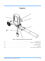
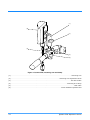
1
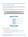
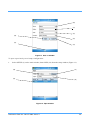
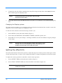
Vinten Radamec
Quattro PDA
Operators Guide
V4015-4980
Robotic Camera Control Systems
Quattro PDA
Operators Guide
Original Instructions
Publication Part No. V4015-4980 Issue 2
Copyright © Vitec Group plc 2009
All rights reserved throughout the world. No
part of this document may be stored in a
retrieval system. transmitted, copied or
reproduced in any way including, but not
limited to, photocopy, photograph, magnetic
or other record without the prior agreement
and permission in writing of Vitec Group plc.
Trademarks
Vinten Radamec® and Vinten® are
registered trademarks of the Vitec Group plc.
Windows Mobile® is a registered trademark
of the Microsoft Corporation.
Important information about this document
Information contained in this document is
subject to change. Camera Dynamics
Limited reserves the right, without notice, to
make changes in equipment design or
performance as progress in engineering,
manufacturing or technology may warrant.
Published by:
Technical Publications Department
William Vinten Building
Western Way
Bury St Edmunds
Suffolk IP33 3TB
UK
Tel: +44 1284 752 121
Fax: +44 1284 750 560
Printed in Great Britain by DPS, Newmarket, Suffolk
Safety - Read This First
Understanding these instructions
English
The original instructions presented in this operators guide were written in English, and subsequently
translated into other languages. If you are unable to understand these instructions, contact Vinten
Radamec or your distributor to obtain a translation of the original instructions (EU Countries).
БЪЛГАРСКИ
Оригиналните инструкции, представени в настоящото ръководство на производителя, бяха
написани на английски език, а след това - преведени на други езици. Ако не разбирате тези
езици, свържете се с Vinten Radamec или с Вашия дистрибутор, за да получите оригиналните
инструкции (за страните от Европейския съюз).
Česky
Pokyny uvedené v této operátorské příručce byly původně napsány anglicky a následně byly
přelo_eny do ostatních jazyků. Nerozumíte-li těmto pokynům, kontaktujte společnost Vinten Radamec
nebo svého distributora, abyste získali překlad originálních pokynů (členské státy EU).
Danish
De originale instruktioner, der præsenteres i denne betjeningsvejledning, er skrevet på engelsk og
derefter oversat til andre sprog. Hvis du ikke forstår disse instruktioner bedes du kontakte Vinten
Radamec eller vor forhandler for at få en oversættelse af de originale instruktioner (EU-lande).
Deutsch
Die Originalanleitung in diesem Bedienungshandbuch wurde auf Englisch verfasst und anschließend
in andere Sprachen übersetzt. Bei Verständnisproblemen in einer der übersetzten Sprachen
kontaktieren Sie bitte Vinten Radamec oder Ihren Fachhändler; dort erhalten Sie eine Übersetzung
der ursprünglichen Anleitung (EU-Staaten).
Eesti
Käesoleva kasutajajuhendi algtekst on koostatud inglise keeles ning seejärel tõlgitud teistesse
keeltesse. Kui juhend osutub teie jaoks arusaamatuks, võtke juhendi emakeelse tõlke hankimiseks
ühendust Vinten Radameci või kohaliku esindajaga (Euroopa Liidu riigid).
Ελληνικά
Οι αρχικές οδηγίες αυτού του οδηγού για το χειριστή συντάχθηκαν στα Αγγλικά και μεταφράστηκαν στη
συνέχεια σε άλλες γλώσσες. Εάν δυσκολεύεστε να καταλάβετε αυτές τις οδηγίες, επικοινωνήστε με τη
Vinten Radamec ή το διανομέα σας για να λάβετε μια μετάφραση των αρχικών οδηγιών (Χώρες ΕΕ).
Español
Las instrucciones originales que se indican en esta guía del operador se han redactado en inglés y
posteriormente se han traducido a otros idiomas. Si no entiende estas instrucciones, póngase en
contacto con Vinten Radamec o con su distribuidor para obtener una traducción de las instrucciones
originales (para países de la UE).
Français
Les instructions originales présentées dans ce guide d'utilisation ont été écrites en anglais puis
traduites dans d'autres langues. Si vous ne comprenez pas ces instructions, contactez Vinten
Radamec ou votre revendeur pour obtenir une traduction des instructions originales (pour les pays de
l'UE).
Gaeilge
Scríobhadh na treoracha bunaidh don treoirleabhar oibritheora seo as Béarla, agus aistríodh iad go
teangacha eile ina dhiaidh sin. Mura bhfuil tú in ann na treoracha seo a thuiscint, téigh i dteagmháil le
Vinten Radamec nó le do dháileoir, chun aistriúchán de na treoracha bunaidh a fháil (Tíortha an AE).
Italiano
Le istruzioni originali presentate in questa guida per l'operatore sono in lingua inglese e
successivamente tradotte nelle altre lingue. Qualora le istruzioni non fossero disponibili nella lingua
desiderata, potete contattare Vinten Radamec o il vostro distributore per ricevere la traduzione delle
istruzioni originali (Paesi UE).
Publication Part No. V4015-4980 Issue 2
3
Latviešu
Šajā operatora rokasgrāmatā iekļautie norādījumi sākotnēji tika sarakstīti angļu valodā un pēc tam
pārtulkoti citās valodās. Ja nesaprotat šos norādījumus svešvalodā, sazinieties ar Vinten Radamec vai
tirgotāju, lai saņemtu norādījumu tulkojumu (kādā no ES dalībvalstu valodām).
Lietuvių
Šiame operatoriaus vadove pristatomos pirminės instrukcijos parašytos anglų kalba ir vėliau išverstos
į kitas kalbas. Jei šių instrukcijų nesuprantate, susisiekite su „Vinten Radamec“ arba savo platintoju ir
gaukite pirminių instrukcijų vertimą (ES šalies kalba).
Magyar
A kezeloi útmutatóban található utasítások angol nyelven íródtak, és utólag fordították azokat más
nyelvekre. Ha nem érti ezen utasításokat, kérjük, vegye fel a kapcsolatot a Vinten Radamecnel vagy
a helyi képviselettel, és igényelje az eredeti utasítások fordítását (EU országok).
Malti
L-istruzzjonijiet originali ippreżentati f'din il-gwida ta' operaturi kienu miktuba bl-Ingliż, u sussegwentement maqluba fl-lingwi ohra. Jekk ma tistax tifhem dawn l-istruzzjonijiet, ikkuntattja lil Vinten Radamec
jew id-distributur tieghek biex tikseb traduzzjoni ta' l-istruzzjonijiet originali (Pajjiżi ta' UE).
Nederlands
De oorspronkelijke instructies in deze bedieningshandleiding zijn geschreven in het Engels en
vervolgens in andere talen vertaald. Als het onmogelijk is deze instructies te begrijpen, neemt u
contact op met Vinten Radamec of met uw distributeur om een vertaling te bemachtigen van de
oorspronkelijke instructies (EG-landen).
Polski
Oryginalne instrukcje zamieszczone w niniejszym podręczniku operatora zostały napisane w języku
angielskim, a następnie przetłumaczone na inne języki. Jeśli nie rozumieją Państwo tych instrukcji,
prosimy skontaktować się z siedzibą lub dystrybutorem Vinten Radamec, aby uzyskać tłumaczenie
oryginalnych instrukcji (kraje UE).
Português
As instruções originais apresentadas no guia do operador foram escritas em Inglês e traduzidas para
outros idiomas. Se não conseguir compreender estas instruções contacte a Vinten Radamec ou o seu
distribuidor para obter a tradução das instruções originais (Países da UE).
Română
Instrucţiunile originale prezentate în acest ghid pentru operatori au fost scrise în limba engleză, şi
traduse ulterior în alte limbi. În cazul în care nu înţelegeţi aceste instrucţiuni, contactaţi Vinten Radamec sau distribuitorul dumneavoastră pentru a obţine o traducere a instrucţiunilor originale (Ţările
UE).
Slovensky
Pôvodné pokyny, uvedené v tomto návode na obsluhu, boli napísané v anglictine a následne
preložené do iných jazykov. Ak nerozumiete týmto pokynom, obrátte sa na spolocnost Vinten
Radamec alebo vášho distribútora, aby vám zaslal preklad originálnych pokynov (krajiny EÚ).
Slovenščina
Originalno besedilo teh navodil za uporabo je bilo napisano v angleščini in prevedeno v ostale jezike.
Če ne razumete teh navodil, se obrnite na podjetje Vinten Radamec ali lokalnega zastopnika, ki vam
bo posredoval originalna navodila (velja za dr_ave EU).
Suomi
Tähän käyttäjän oppaaseen sisältyvät ohjeet on kirjoitettu alun perin englanniksi ja käännetty sitten
muille kielille. Ellet ymmärrä näitä ohjeita, ota yhteyttä Vinten Radameciin tai jälleenmyyjään ja pyydä
alkuperäisten ohjeiden käännöstä (EU-maat).
Svenska
Instruktionerna i denna handbok skrevs ursprungligen på engelska och har sedan översatts till flera
språk. Om du inte förstår dessa instruktioner, kontakta Vinten Radamec eller din återförsäljare för en
ny översättning av originalinstruktionerna (EU-länder).
4
Quattro PDA Operators Guide
Safety guidelines
Warning symbols in this guide
Where there is a risk of personal injury or injury to others, comments appear
highlighted by the word WARNING!—supported by the warning triangle symbol.
Where there is a risk of damage to the product, associated equipment, process or
surroundings, comments appear highlighted by the word CAUTION!
Warning symbols on the product
The following warning symbol may appear on the product.
On encountering the warning
triangle and open book symbols it is
imperative that you consult this
operators guide before using this
product or attempting any
adjustment or repair.
Publication Part No. V4015-4980 Issue 2
5
Important safety instructions
1. Take heed of warnings and instructions
You should read all of the safety instructions
before operating the equipment. Retain this
operators guide for future reference and adhere
to all warnings in the guide or on the
equipment. Do not attempt to operate this
equipment if you do not understand how to
operate it.
2. Usage Statement
Do not use this product for any other purpose
other than that specified in this usage
statement. The Vinten Radamec Quattro PDA
is designed for use in television studios to
configure and calibrate Vinten ‘E’ pan/tilt
heads and the Quattro SE pedestal for use with
studio VR systems. The Quattro PDA is
intended to be used by television camera
operators familiar with the Quattro system.
3. Water, moisture and dust
Protect the product from water, moisture and
dust. The presence of electricity near water can
be dangerous. Do not use the product near
water and take care that liquids are not spilled
onto the equipment. For outdoor applications,
only use products that are specifically designed
for outdoor usage.
4. Climate
The equipment should not be used outside the
operating limits. Refer to the Technical
Specifications for the operating range of the
equipment.
5. Cleaning
We encourage regular cleaning of the product.
• Do not use oil or grease on any exposed part of
the equipment. This is unnecessary and traps dirt
which acts as an abrasive.
• External electrical connection ports should only
be cleaned with a semi-stiff brush or a clean, dry
air supply.
6. Servicing
You should not attempt to service the
equipment. Contact Camera Dynamics Ltd or
your local distributor to arrange servicing.
Maintenance beyond that detailed in this guide
must be performed by competent personnel in
accordance with the procedures in the
Technical or Maintenance Manual for the
equipment.
7. Notes about Robotic equipment
Display prominent warning signs in studios,
alerting personnel that robotic equipment is
present and may move without warning. Ensure
personnel remain a minimum of 1 m (40 inches)
clear of robotic equipment in use.
Operators must familiarise themselves with the
resulting working envelope of robotic products
including all ancillary equipment (lens, zoom
and focus controls, viewfinder, prompter etc.),
to prevent inadvertent collisions.
Only operate robotic products remotely when
you can see them to avoid harm to personnel
and collisions with obstacles and other hazards.
8. Power sources
Only connect the equipment to a power supply
of the type described in the Technical
Specifications or as marked on the equipment.
9. Cables
Always ensure that all power and auxiliary
communications cables are routed so that they
do not present any danger to personnel. Take
care when routing cables in areas where robotic
equipment is in use.
• Do not use solvent or oil based cleaners,
abrasives or wire brushes to remove
accumulations of dirt as these damage the
protective surfaces. To clean mechanical
surfaces, use only detergent based cleaners.
6
Quattro PDA Operators Guide
Certificates and Compliances
The Quattro PDA conforms to the following European Directives:
2004/108/EC (Electromagnetic Compatibility Directive)
2006/95/EC (Low Voltage Directive)
1999/5/EC Radio and Telecommunications Terminal Equipment
This product has been tested and found compliant to the following test standards:
EMC:
IEC 61000-4-2:2001 (1.2)
IEC 61000-3-2:2005 (3rd Edition)
IEC 61000-4-3:2006 (3rd Edition)
IEC 61000-3-3:2005 (1.2) &
IEC 61000-4-4:2004 (2.4)
EN60950-1:2001
IEC 61000-4-5:2001 (1.1)
EN 55022:1998 & A1:2005 & A2:2003
IEC 61000-4-6:2003 (2nd Edition)
ETSI EN 300 328 (1.3.1, 2001-12)
IEC 6100004-8:2001 (1.1)
ETSI EN 301 489-17 (1.1.1)
IEC 61000-4-11:2004 (2nd Edition)
ETSI EN 301 489-1 (1.3.1)
Other certification
FCC:
Class B
Publication Part No. V4015-4980 Issue 2
7
Caring for the environment by recycling
Recycling old electrical and electronic equipment
This symbol on the product or on its packaging indicates that this product must not
be treated as household waste (applicable in the European Union and European
countries with separate collection systems). It shall be handed over to the
applicable collection point for the recycling of electrical and electronic equipment.
Please visit www.vinten.com/recycle for details.
By ensuring this product is disposed of correctly, you will help prevent potentially
negative consequences for the environment and human health, and help conserve
natural resources.
Disposal of waste batteries
Any batteries included with this product must not be treated as household waste (applicable in the
European Union and European countries with separate collection systems). By ensuring these
batteries are disposed of correctly, you will help prevent potentially negative consequences for the
environment and human health, and help conserve natural resources. Please view the section on how
to remove the battery from the product safely using the instructions in the PDA user manual. Hand
the battery over to the applicable collection point for recycling waste batteries. Please visit
www.vinten.com/recycle for details.
8
Quattro PDA Operators Guide
Technical Specification
Dimensions:
Weight . . . . . . . . . . . . . . . . . . . . . . . . . . . . . . . . . . . . . . . . . . . . . . . . . . . . . . . . . . . . . . . . . . . 482 g (1.06 lbs)
Length . . . . . . . . . . . . . . . . . . . . . . . . . . . . . . . . . . . . . . . . . . . . . . . . . . . . . . . . . . . . . . . . . . 16.5 cm (6.5 in.)
Width . . . . . . . . . . . . . . . . . . . . . . . . . . . . . . . . . . . . . . . . . . . . . . . . . . . . . . . . . . . . . . . . . . . . . 8.9 cm (3.5 in.)
Height . . . . . . . . . . . . . . . . . . . . . . . . . . . . . . . . . . . . . . . . . . . . . . . . . . . . . . . . . . . . . . . . . . . . 4.3 cm (1.7 in.)
Power:
Power consumption peak . . . . . . . . . . . . . . . . . . . . . . . . . . . . . . . . . . . . . . . . . . . . . . . . . . . . . . . . . . . . . 10 W
Power adaptor input voltage . . . . . . . . . . . . . . . . . . . . . . . . . . . . . . . . . . . Autoranging 110-240V AC 50/60 Hz
PDA input voltage . . . . . . . . . . . . . . . . . . . . . . . . . . . . . . . . . . . . . . . . . . . . . . . . . . . . . . . . . . 10-20V DC ±5%
Environmental:
Operating temperature . . . . . . . . . . . . . . . . . . . . . . . . . . . . . . . . . . . . . . . . . . . . . . . . . . . . . . . . . . -30°C–50°C
Protocols:
Communication facilities . . . . . . . . . . . . . . . . . . . . . . . . . . . . . . . . . . . . . . . . . . . . . . . . . . . . . . . . . . . . . RS232
Software:
PDA Operating Platform . . . . . . . . . . . . . . . . . . . . . . . . . . . . . . . . . . . . . . . . . . .Microsoft Windows Mobile 5.0
Quattro PDA Software Version . . . . . . . . . . . . . . . . . . . . . . . . . . . . . . . . . . . . . . . . . . . . . . . . . . . . . . . . . . 1.14
Specifications are subject to change without notice.
Publication Part No. V4015-4980 Issue 2
9
10
Quattro PDA Operators Guide
Contents
Page
Safety - Read This First . . . . . . . . . . . . . . . . . . . . . . . . . . . . . . . . . . . . . . . . . . . . . . . . . . . . . . . . . . . . . . . . 3
Safety guidelines. . . . . . . . . . . . . . . . . . . . . . . . . . . . . . . . . . . . . . . . . . . . . . . . . . . . . . . . . . . . . . . . . . 5
Important safety instructions. . . . . . . . . . . . . . . . . . . . . . . . . . . . . . . . . . . . . . . . . . . . . . . . . . . . . . . . . 6
Certificates and Compliances . . . . . . . . . . . . . . . . . . . . . . . . . . . . . . . . . . . . . . . . . . . . . . . . . . . . . . . . . . . 7
Caring for the environment by recycling . . . . . . . . . . . . . . . . . . . . . . . . . . . . . . . . . . . . . . . . . . . . . . . . 8
Technical Specification . . . . . . . . . . . . . . . . . . . . . . . . . . . . . . . . . . . . . . . . . . . . . . . . . . . . . . . . . . . . . . . . 9
Figures . . . . . . . . . . . . . . . . . . . . . . . . . . . . . . . . . . . . . . . . . . . . . . . . . . . . . . . . . . . . . . . . . . . . . . . . . . . . . 13
Installation
Unpacking . . . . . . . . . . . . . . . . . . . . . . . . . . . . . . . . . . . . . . . . . . . . . . . . . . . . . . . . . . . . . . . . . . . . . . 15
Fitting the Quattro PDA to the pan bar handle . . . . . . . . . . . . . . . . . . . . . . . . . . . . . . . . . . . . . . . . . . 15
Connecting the Quattro PDA to the HPM . . . . . . . . . . . . . . . . . . . . . . . . . . . . . . . . . . . . . . . . . . . . . . 16
Powering Up . . . . . . . . . . . . . . . . . . . . . . . . . . . . . . . . . . . . . . . . . . . . . . . . . . . . . . . . . . . . . . . . . . . . 16
Operation . . . . . . . . . . . . . . . . . . . . . . . . . . . . . . . . . . . . . . . . . . . . . . . . . . . . . . . . . . . . . . . . . . . . . . . . . . . 17
Operating the PDA . . . . . . . . . . . . . . . . . . . . . . . . . . . . . . . . . . . . . . . . . . . . . . . . . . . . . . . . . . . . . . . 17
Launching the Quattro PDA application . . . . . . . . . . . . . . . . . . . . . . . . . . . . . . . . . . . . . . . . . . . . . . . 17
About calibrating the Quattro SE system . . . . . . . . . . . . . . . . . . . . . . . . . . . . . . . . . . . . . . . . . . . . . . 17
Initial system start up . . . . . . . . . . . . . . . . . . . . . . . . . . . . . . . . . . . . . . . . . . . . . . . . . . . . . . . . . . . . . 17
Zeroing axes . . . . . . . . . . . . . . . . . . . . . . . . . . . . . . . . . . . . . . . . . . . . . . . . . . . . . . . . . . . . . . . . . . . . 19
How to zero the pan, tilt, zoom and focus axes . . . . . . . . . . . . . . . . . . . . . . . . . . . . . . . . . . . . 19
How to zero the Quattro SE pedestal height axis . . . . . . . . . . . . . . . . . . . . . . . . . . . . . . . . . . . 20
How to zero the Quattro SE pedestal steering (wheels). . . . . . . . . . . . . . . . . . . . . . . . . . . . . . 20
Homing the Quattro SE system . . . . . . . . . . . . . . . . . . . . . . . . . . . . . . . . . . . . . . . . . . . . . . . . . . . . . 21
Homing a MK I pedestal . . . . . . . . . . . . . . . . . . . . . . . . . . . . . . . . . . . . . . . . . . . . . . . . . . . . . . 21
Homing a MK II pedestal . . . . . . . . . . . . . . . . . . . . . . . . . . . . . . . . . . . . . . . . . . . . . . . . . . . . . 23
Displaying coordinate information for the camera, pedestal and head axes. . . . . . . . . . . . . . . . . . . . 26
Publication Part No. V4015-4980 Issue 2
11
Contents (Cont)
Page
Communicating navigational and positional data to the VR system . . . . . . . . . . . . . . . . . . . . . . . . . . 26
Set up and configuration . . . . . . . . . . . . . . . . . . . . . . . . . . . . . . . . . . . . . . . . . . . . . . . . . . . . . . . . . . . 27
Displaying the current software and firmware versions . . . . . . . . . . . . . . . . . . . . . . . . . . . . . . 28
Opening and saving configurations . . . . . . . . . . . . . . . . . . . . . . . . . . . . . . . . . . . . . . . . . . . . . 28
Changing the Display options . . . . . . . . . . . . . . . . . . . . . . . . . . . . . . . . . . . . . . . . . . . . . . . . . . 30
Setting the offset trim . . . . . . . . . . . . . . . . . . . . . . . . . . . . . . . . . . . . . . . . . . . . . . . . . . . . . . . . . . . . . 30
Maintenance
General . . . . . . . . . . . . . . . . . . . . . . . . . . . . . . . . . . . . . . . . . . . . . . . . . . . . . . . . . . . . . . . . . . . . . . . . 32
Routine checks . . . . . . . . . . . . . . . . . . . . . . . . . . . . . . . . . . . . . . . . . . . . . . . . . . . . . . . . . . . . . . . . . . 32
Routine checks . . . . . . . . . . . . . . . . . . . . . . . . . . . . . . . . . . . . . . . . . . . . . . . . . . . . . . . . . . . . . . . . . . 32
Adjustments . . . . . . . . . . . . . . . . . . . . . . . . . . . . . . . . . . . . . . . . . . . . . . . . . . . . . . . . . . . . . . . . . . . . 32
Software upgrades . . . . . . . . . . . . . . . . . . . . . . . . . . . . . . . . . . . . . . . . . . . . . . . . . . . . . . . . . . . . . . . 32
Troubleshooting . . . . . . . . . . . . . . . . . . . . . . . . . . . . . . . . . . . . . . . . . . . . . . . . . . . . . . . . . . . . . . . . . . . . . 33
Parts list . . . . . . . . . . . . . . . . . . . . . . . . . . . . . . . . . . . . . . . . . . . . . . . . . . . . . . . . . . . . . . . . . . . . . . . . . . . . 34
12
Quattro PDA Operators Guide
Figures
(1)
(6)
(2)
(3)
(5)
(4)
Figure 1 Quattro PDA mounted on the pan bar handle
(1). . . . . . . . . . . . . . . . . . . . . . . . . . . . . . . . . . . . . . . . . . . . . . . . . . . . . . . . . . . . . . . Mounting arm
(2). . . . . . . . . . . . . . . . . . . . . . . . . . . . . . . . . . . . . . . . . . . . . . . . . . .Mounting arm adjustment knob
(3). . . . . . . . . . . . . . . . . . . . . . . . . . . . . . . . . . . . . . . . . . . . . . . . . . . . . . . . . . . . . . Pan bar handle
(4). . . . . . . . . . . . . . . . . . . . . . . . . . . . . . . . . . . . . . . . . . . . . . . . . . . . . . . . . . Mounting arm clamp
(5). . . . . . . . . . . . . . . . . . . . . . . . . . . . . . . . . . . . . . . . . . . . . . . . . . . . . . . . . . . . . . . . . . PDA cable
(6). . . . . . . . . . . . . . . . . . . . . . . . . . . . . . . . . . . . . . . . . . . . . . . . . . . . Vinten Radamec Quattro PDA
Publication Part No. V4015-4980 Issue 2
13
(1)
(6)
(2)
(5)
(3)
(4)
Figure 2 Quattro PDA, mounting arm and clamp
(1). . . . . . . . . . . . . . . . . . . . . . . . . . . . . . . . . . . . . . . . . . . . . . . . . . . . . . . . . . . . . . . Mounting arm
(2). . . . . . . . . . . . . . . . . . . . . . . . . . . . . . . . . . . . . . . . . . . . . . . . . . .Mounting arm adjustment knob
(3). . . . . . . . . . . . . . . . . . . . . . . . . . . . . . . . . . . . . . . . . . . . . . . . . . . . . . . . . . . . . . Pan bar handle
(4). . . . . . . . . . . . . . . . . . . . . . . . . . . . . . . . . . . . . . . . . . . . . . . . . . . . . . . . . . Mounting arm clamp
(5). . . . . . . . . . . . . . . . . . . . . . . . . . . . . . . . . . . . . . . . . . . . . . . . . . . . . . . . . . . . . . . . . . PDA cable
(6). . . . . . . . . . . . . . . . . . . . . . . . . . . . . . . . . . . . . . . . . . . . . . . . . . . . Vinten Radamec Quattro PDA
14
Quattro PDA Operators Guide
Installation
The Vinten Radamec Quattro PDA simplifies the setup of the Quattro SE virtual tracking system,
allowing operators to easily configure the Head Processing Module (HPM) communication settings
to suit the studio Virtual Reality (VR) system. The Quattro PDA runs the Vinten Radamec Quattro
application software that provides various touchscreen options to allow operators to configure the VR
output, review encoder output and zero movement axes on the connected Quattro-SE pedestal and
Vector 950E or Vision 250E pan/tilt heads. The Quattro PDA is supplied with an articulated arm and
is mounted onto the non-telescopic part of the pan bar handle.
Unpacking
The Quattro PDA is supplied fitted with an articulated clamp arm for mounting onto the pan bar
handle. The Quattro PDA is typically supplied with:
•
AC charger (universal voltage)
•
USB cable
•
Captured full-size stylus
•
PDA user documentation
•
Screwdriver
Additionally, the Quattro PDA is supplied with:
•
PDA power/data cable (V3980-5036) for connecting the Quattro PDA to the HPM.
Fitting the Quattro PDA to the pan bar handle
The Quattro PDA should be positioned on the pan bar handle so that the camera operator can easily
view the PDA screen and perform various functions using the touchscreen.
To fit the Quattro PDA to the pan bar handle:
1.
Ensure that the pan bar is correctly attached to the head.
2.
Remove the two screws securing the mounting arm clamp (4) to the PDA mounting arm (1).
3.
Place the PDA mounting arm (1) over the fixed portion of the pan bar handle. Place the mounting
arm clamp (4) under the pan bar handle and secure the clamp to the arm using the two screws.
CAUTION!
DO NOT attach the Quattro PDA to the telescopic part of the pan
bar handle because you may damage the handle.
Publication Part No. V4015-4980 Issue 2
15
4.
Adjust the position of the Quattro PDA on the pan bar handle so that camera operators can easily
view the PDA screen and access the functions using the stylus. Loosen the mounting arm adjustment
knob (2) and position the Quattro PDA, then tighten the knob to secure the PDA into the required
position.
NOTE:
Mounting the Quattro PDA onto the pan bar handle will affect the fore
and aft balance of the head. Check the balance of the head after fitting
the Quattro PDA.
Connecting the Quattro PDA to the HPM
The Quattro PDA is connected to the HPM that is mounted onto a bracket secured to the base of the
head. Using a combined power and data cable (5), the Quattro PDA communicates with the HPM and
is also powered by the HPM. When connected to a powered HPM, the Quattro PDA internal battery
is constantly being charged. There is no requirement to charge the PDA battery unless it has been
disconnected from the HPM and operated for several hours without an external power source (refer
to the PDA user documentation for instructions about recharging the PDA).
CAUTION!
Switch off the power to the HPM, Quattro SE pedestal and the head
before connecting the Quattro PDA.
To connect the Quattro PDA to the HPM:
NOTE:
The PDA cable has a single serial connector at one end that connects
to the HPM and a combination of serial connector and power plug at
the other end which connects to the PDA.
1.
Connect the PDA serial connector to the Comms port on the Quattro PDA and then plug in the DC
power connector to the Power input socket. Refer to the PDA user documentation for Comms port
and power socket location.
2.
Connect the HPM serial connector to the PDA Comms port on the HPM.
Powering Up
When the Quattro PDA has been installed, switch on the power to the Quattro SE pedestal, head and
HPM. Refer to the PDA user documentation for instructions on powering up the PDA.
16
Quattro PDA Operators Guide
Operation
Operating the PDA
The PDA is supplied with a number of software applications installed, including the Quattro
application. Refer to the PDA user documentation for operating instructions including how to use the
touchscreen and stylus.
Launching the Quattro PDA application
To launch the Quattro application:
•
From the PDA menu, select START > QUATTRO.
When the Quattro application is launched, the main window appears (Figure 3). The main window
comprises a main message window (13) and a series of function keys (2)–(5), (9)–(12).
About calibrating the Quattro SE system
Pedestal floor travel and orientation are set relative to a studio floor target (Figure 6) (Figure 7),
which is detected by sensors mounted in the base of the pedestal. All other axes of movement are
homed either relative to an index point on the axis encoder or a repeatable end-stop on the axis. This
ensures that zoom, focus, pan, tilt and height axes produce repeatable positional feedback.
Initial system start up
When the HPM is powered up, the Quattro PDA application automatically begins to configure the
Quattro SE system (comprising the Quattro-SE pedestal and either the Vector 950E or the Vision
250E pan/tilt head). The Quattro PDA application will prompt you throughout the initial start up
process required to calibrate all movement axes, pan, tilt, zoom, focus, height and wheels (steering).
Details of the steps in this process are explained in the following sections of this guide.
When the initial start up calibration procedure is complete, each calibration step can be selected
individually by the operator. This allows zeroing and referencing of a specific axis without having to
repeat the system calibration.
NOTE:
The Genlock signal indicators (8) display a ‘tick’ when a signal
is detected from the connected equipment to aid diagnostics.
The left hand box indicates a Genlock signal is present at the
pedestal base and the right hand box indicates a Genlock signal
is present at the head.
Publication Part No. V4015-4980 Issue 2
17
(13)
(1)
(12)
(2)
(11)
(3)
(10)
(4)
(9)
(5)
(8)
(7)
(6)
Figure 3 Quattro PDA application, main window
(1). . . . . . . . . . . . . . . . . . . . . . . . . . . . . . . . . . . . . . . . . . . . . . . . . . . . . . Axis display scroll buttons
(2). . . . . . . . . . . . . . . . . . . . . . . . . . . . . . . . . . . . . . . . . . . . . . . . . . . . . . . . . . . . . . . .Setup button
(3). . . . . . . . . . . . . . . . . . . . . . . . . . . . . . . . . . . . . . . . . . . . . . . . . . . . . . . . . . . . . Zero axes button
(4). . . . . . . . . . . . . . . . . . . . . . . . . . . . . . . . . . . . . . . . . . . . . . . . . . . . . . . . . . . . Offset trim button
(5). . . . . . . . . . . . . . . . . . . . . . . . . . . . . . . . . . . . . . . . . . . . . . . . . . . . . . . . . Run navigation button
(6). . . . . . . . . . . . . . . . . . . . . . . . . . . . . . . . . . . . . . . . . . . . . . . . . . . . . . Navigation mode indicator
(7). . . . . . . . . . . . . . . . . . . . . . . . . . . . . . . . . . . . . . . . . . . . . . . . . . . . . . Communications indicator
(8). . . . . . . . . . . . . . . . . . . . . . . . . . . . . . . . . . . . . . . . . . . . . . . . . . . . . . . Genlock signal indicators
(9). . . . . . . . . . . . . . . . . . . . . . . . . . . . . . . . . . . . . . . . . . . . . . . . . . . . . . Axis display on / off toggle
(10) . . . . . . . . . . . . . . . . . . . . . . . . . . . . . . . . . . . . . . . . . . . . . . . . . . . . . . . . .Target homing button
(11) . . . . . . . . . . . . . . . . . . . . . . . . . . . . . . . . . . . . . . . . . . . . . . . . . . . . . . . . . . . . . . Accept button
(12) . . . . . . . . . . . . . . . . . . . . . . . . . . . . . . . . . . . . . . . . . . . . . . . . . . . . . . . . . . . . . . Cancel button
(13) . . . . . . . . . . . . . . . . . . . . . . . . . . . . . . . . . . . . . . . . . . . . . . . . . . . . . . . . Main message window
18
Quattro PDA Operators Guide
Zeroing axes
Using the Quattro PDA application, operators can zero the pan and tilt axes on the head, zoom and
focus axes on the camera lens, and the height and steering (wheels) on the Quattro SE pedestal.
•
From the Quattro PDA main window (Figure 3), select ZERO (3). The Zero axes window
appears (Figure 4).
(14)
(15)
(16)
(17)
Figure 4 Zero axes window
How to zero the pan, tilt, zoom and focus axes
To zero the pan, tilt, zoom and focus axes:
1.
From the Zero axes window (Figure 4), select ZERO PTZF (14).
2.
Move the zoom and focus axes through their entire range—end stop to end stop—and then select
ACCEPT (11) on the main window when prompted.
3.
A message appears indicating that the lens is zeroed and prompts the operator to lock the tilt axis in
the horizontal position and the pan axis is set either:
•
with indicator marks aligned on the pan axis (if marks are present), or
•
with the pan axis rotated so that the camera points straight ahead, toward the front of the
pedestal.
Publication Part No. V4015-4980 Issue 2
19
4.
When prompted, pan the head to the left until the index marker is found and a message appears
indicating the axis is homed.
NOTE:
5.
The pan axis index marker will need to be re-referenced if the head is
rotated through an angle greater than 360°.
When prompted, unlock the tilt axis and tilt the head fully up and down until the index marker is
found and a message appears indicating the axis is homed.
To return to the Quattro PDA main window without zeroing any axes, select CANCEL (17) on the
Zero Axes window.
How to zero the Quattro SE pedestal height axis
To zero the Quattro SE pedestal height axis:
1.
From the Zero Axes window, select ZERO HEIGHT (15).
2.
When prompted, lock the pedestal column in the fully down position.S
3.
Select ACCEPT (11) on the main window to set the height axis.
To return to the Quattro PDA main window without zeroing the height axis, select CANCEL (17) on
the Zero axes window.
How to zero the Quattro SE pedestal steering (wheels)
NOTE:
Ensure the pedestal is set to ‘crab’ mode (Crab/steer changeover
pedal). Refer to the Quattro SE pedestal operators guide (publication
number V3851-4980) for information on changing the mode.
To zero the angle encoders for all three wheels on the Quattro SE pedestal:
1.
From the Zero axes window, select ZERO WHEELS (16).
2.
When prompted, steer the wheels until messages in the Quattro PDA main message window (13)
indicate that all three wheel angle encoders are zeroed—with a separate message for each wheel.
3.
When all three wheel angle encoders are zeroed, a message appears indicating that zeroing is
complete.
To return to the Quattro PDA main window without zeroing the steering, select CANCEL (17) on the
Zero axes window.
20
Quattro PDA Operators Guide
Homing the Quattro SE system
When the Quattro SE system is initially powered up it will set X, Y (floor) travel and pedestal
orientation to zero, therefore the pedestal must be ‘homed’ relative to a floor target. Periodically the
error in X, Y (floor) travel and pedestal orientation will increase to a level where it is necessary to
‘rehome’ the pedestal relative to a floor target.
There are currently two versions of the Quattro-SE pedestal, each using a different optical sensor
arrangement and floor target. The MK I pedestal uses a three-line floor target (Figure 6) and the MK
II pedestal uses a two-line reflective tape target (Figure 7).
NOTE:
•
Before you start the homing process, check which version of pedestal
you are using by looking at the floor target installed.
From the Quattro PDA main window, select HOMING (10). The Homing window appears
(Figure 5).
(18)
(19)
(20)
(21)
Figure 5 Homing window
Homing a MK I pedestal
To home a MK I pedestal to the studio target datum (X and Y axis):
1.
Select 3 LINE TARGET (18) from the homing window (Figure 5). You can return to the main
window without affecting homing settings by selecting cancel (21).
2.
Position the pedestal over the floor target as shown in (Figure 6), ensuring that the pedestal
orientation is also approximately correct.
Publication Part No. V4015-4980 Issue 2
21
(22)
Figure 6 MK I floor target homing and target origin
NOTE:
The orientation of the MK I pedestal shown in (Figure 6) positions the
opto sensor (22) in the best position for homing.
The MK I pedestal uses one opto sensor (22) to locate the floor target
(Figure 6).
The origin of the MK I floor target lies at the point where the edges of
all three lines intersect, as shown in (Figure 6).
3.
Align the steering so that the pedestal can travel across the target at approximately 45° (Figure 6)
allowing the opto sensor (22) to run across all three lines on the target, and then select ACCEPT (11)
on the main window.
NOTE:
4.
If required, alternative pedestal orientations can be used; as long as
the operator ensures that the opto sensor (22) will travel across all
three lines on the target (Figure 6).
When prompted, run the pedestal across the target without steering. A message is displayed as each
of the three lines on the target are found.
NOTE:
An error message appears if the operator steers the pedestal during
this movement, or if the target lines are not found after a certain
distance of travel.
When all three target lines are found, a message appears indicating that homing is complete and the
main window appears (Figure 3).
22
Quattro PDA Operators Guide
Homing a MK II pedestal
To home a MK II pedestal to the studio target datum (X and Y axis):
1.
Select either HOME PEDAL AT FRONT (19) or HOME PEDAL AT REAR (20) from the Homing
window (Figure 5), depending on the orientation of the pedestal relative to the floor target—see
(Figure 8). You can return to the main window without affecting homing settings by selecting cancel
(21).
NOTE:
The origin of the MK II floor target lies at the point where the bottom
edge of the X-axis tape intersects with the right-hand edge of the Yaxis tape, as shown in (Figure 7).
The X and Y axis reflective tape strips must be perpendicular to each
other, but do not have to physically intersect.
The MK II pedestal uses two opto sensors (22) to locate the floor
target (Figure 7).
(22)
Figure 7 MK II floor target origin
2.
The pedestal must detect each axis (X and Y) individually. To reference the X-axis the pedestal must
be pushed so that both sensors cross the horizontal X-axis tape. The path of the pedestal across the
X-axis can be ±60° to the vertical Y-axis, approaching from above or below the X-axis with the
changeover pedal (23) either toward or away from the operator (Figure 8).
Publication Part No. V4015-4980 Issue 2
23
(23)
Home—pedal at front
(23)
Home—pedal at rear
Figure 8 MK II floor target—possible homing paths across X-axis
The edge of the pedestal base does not need to be exactly parallel to the X-axis, but the path across
the X-axis must not be parallel to the line between the two opto sensors (22), i.e. parallel to the back
edge of the pedestal base (Figure 9).
24
Quattro PDA Operators Guide
(22)
Figure 9 MK II floor target—impossible homing path
NOTE:
3.
Once both opto sensors (22) have crossed the X-axis, the pedestal’s
orientation and Y-position are calculated.
To reference the Y-axis the pedestal must be pushed so that one sensor (22) crosses the vertical Yaxis tape.
NOTE:
In practice these two axis referencing movements can be combined in
one diagonal path (Figure 10) which ensures that both opto sensors
first cross the X-axis and then one sensor crosses the Y-axis.
Figure 10 Two examples of referencing both target axes in one path
Publication Part No. V4015-4980 Issue 2
25
4.
When both axes are found, the main window is displayed and a message indicating that homing is
complete appears (Figure 3).
Displaying coordinate information for the
camera, pedestal and head axes
The main message window (13) on the main window can display coordinate information relating to
all axes of the camera, head and pedestal when in navigation mode (5). To display coordinate
information, select AXIS DISPLAY (9) on the main window—the information will continually
update in the main message window (13). Selecting AXIS DISPLAY (9) again will stop the
coordinate information updating, holding the latest coordinate information in the message window
(13). Reselecting AXIS DISPLAY (9) will restart coordinate information updates in the main
message window (13).
NOTE:
The main message window (13) can be configured to show axis
information either as positional measurements (default), encoder
counts (diagnostic) or wheel angles (diagnostic). For more detail refer
to ‘Changing the Display options’ on page 30.
Communicating navigational and positional
data to the VR system
Selecting RUN NAV (5) starts the navigation process and sends positional data to the studio VR
system. The RUN NAV (5) command can only be selected when all three wheel angle encoders have
been zeroed (see How to zero the Quattro SE pedestal steering (wheels) on page 20).
When nav mode is running, the RUN NAV button (5) will change to a STOP NAV button (5) and the
nav mode indicator (6) is selected (displays a ‘tick’). Selecting the STOP NAV button (5) will cause
the Quattro SE pedestal to stop updating its position and will cease VR data packet transmission.
NOTE:
1. Selecting OK (27) to exit the setup display, and accept setup
changes, will turn off NAV MODE (6). Select RUN NAV (5) to reestablish communication to the studio VR system.
2. Ensure that the virtual datum in the VR system corresponds with
the origin of the studio floor target for the Quattro-SE pedestal (Figure
6) (Figure 7).
26
Quattro PDA Operators Guide
Set up and configuration
There are four setup options available to PDA operators with all other options password protected for
technical operators wanting to perform diagnostics and system configuration.
CAUTION!
1.
Adjustments to any setup options requiring password entry
should only be carried out by competent personnel.
2.
Do NOT alter any setup options that you do not fully
understand.
(24)
(29)
(25)
(28)
(26)
(27)
Figure 11 Setup window
Publication Part No. V4015-4980 Issue 2
27
Displaying the current software and firmware versions
To display the software and firmware version information for the Quattro PDA software, HPM and
pedestal (Figure 12), select SETUP (2) on the main window and then ABOUT (25) on the Setup
window (Figure 11). If communication with a device is not established, the software version will
appear as x.xx (Figure 12).
Figure 12 About window
Opening and saving configurations
Alternative setup configurations can be saved and recalled as required. To save a setup configuration:
1.
Select SETUP (2) on the main window, then SAVE AS (29) on the Setup window (Figure 11).
2.
The Save as window appears (Figure 13).
3.
Type the desired file name into the name text box (30) using the touch screen keyboard, accessed by
selecting the keyboard icon (35).
4.
Select either the main memory or the memory card from the drop down menu as the destination
storage location (33).
5.
Select the appropriate SAVE FOLDER (31) from the drop down menu.
6.
Ensure that the file type drop down menu (32) is set to *.dat (32).
7.
Select SAVE (36) to save the setup configuration or CANCEL (34) to exit without saving.
28
Quattro PDA Operators Guide
(30)
(31)
(32)
(36)
(33)
(35)
(34)
Figure 13 Save as window
To open a previously saved setup configuration:
1.
Select SETUP (2) on the main window, then OPEN (24) from the setup window (Figure 11).
(40)
(37)
(39)
(38)
Figure 14 Open window
Publication Part No. V4015-4980 Issue 2
29
2.
If required, select the folder containing the setup files using the drop down menu (40) and ensure
that *.dat file types are displayed (38).
NOTE:
3.
The default location for all setup files (.dat) is the My
Documents\Quattro folder.
Select the required setup file (39) from the list to open it, or CANCEL to exit without opening any
files.
Changing the Display options
The main message window (13) can display either positional measurement data, encoder counts (for
diagnostic use) or wheel angles (for diagnostic use).
To alter the units shown in the main message window (13):
1.
Select SETUP (2) from the main window (Figure 3).
2.
Select either the POSITION, ENCODERS or WHEEL ANGLES options (28).
3.
Select OK (27) to save your settings—selecting CANCEL (26) will exit without saving any changes
to the setup).
NOTE:
Selecting OK (27) to exit the Setup window, and accept the setup
changes, will turn off NAV MODE (6). Select RUN NAV (5) to reestablish communication to the studio VR system.
Setting the offset trim
The offset trim function allows the operator to adjust the physical camera position with respect to the
virtual camera position, to remove error without needing to re-home the pedestal on the floor target.
To adjust the camera position to match the virtual camera position:
1.
Select OFFSET TRIM (4) from the main window (Figure 3).
2.
Select START OFFSET TRIM (41) from the Offset trim window (Figure 15).
NOTE:
30
The START OFFSET TRIM function (41) toggles to STOP OFFSET
TRIM when selected.
Quattro PDA Operators Guide
(41)
(42)
(43)
Figure 15 Offset trim window
3.
Reposition the camera as required to align the camera angle to the virtual camera angle.
NOTE:
Although all movement axes can be corrected using the offset trim
function, the pan axis is the most likely to build an error.
4.
Select STOP OFFSET TRIM (41).
5.
Move the camera and ensure that virtual camera movement matches.
6.
To save the camera trim changes, select OK (43). To revert back to the original settings select
CANCEL (42).
NOTE:
Once saved (43) camera trim changes are permanent. The pedestal
must be re-homed if the camera angle is very different to the virtual
camera angle (see Homing the Quattro SE system on page 21).
Publication Part No. V4015-4980 Issue 2
31
Maintenance
General
The PDA is robustly made to high engineering standards and little attention is required to maintain
serviceability save regular cleaning. Attention to the following points will ensure a long and useful
service life with minimum need for repair. Refer to the User Manuals supplied with the PDA for
instructions on regular maintenance.
Charging the PDA
The PDA will charge when connected to a powered Vinten Radamec HPM (see Connecting the
Quattro PDA to the HPM on page 16). To charge the PDA independently of the HPM, refer to the
PDA User Manual supplied with the device for instructions.
Routine checks
During use, check the data communications with the Vinten Radamec HPM. Re-fit cables if
necessary.
Adjustments
Adjustments to the setup options should only be carried out by competent and trained personnel.
CAUTION!
Do NOT alter any setup options that you do not fully understand.
The equipment may become inoperable
Refer to the appropriate section in the PDA User Manual if any problem is apparent with the device.
Software upgrades
Upgrades to the software may be issued from time to time. All software upgrades are installed and
configured by Camera Dynamics personnel or trained personnel from your local Camera Dynamics
distributor.
32
Quattro PDA Operators Guide
Troubleshooting
Problem
Check
No coordinate information appears in the
message window (13) when the HPM is
turned on.
Close the Quattro application and restart
the application.
No coordinate information appears in the
message window (13) after zeroing the
lens and the head
The PDA is unable to establish
communications with the Quattro-SE
pedestal—verify coms indicator (7) is
unticked.
Check power and ethernet cable
connections at either end of the pedestal
cable management system (into the
pedestal base and the HPM).
If unsuccessful, restart the PDA and power
cycle the HPM.
Coordinate information does not update
and no tracking data is received.
On the PDA, check that the pedestal ‘NAV
MODE’ is turned on—verify navigational
mode indicator (6) is ticked. See
Communicating navigational and
positional data to the VR system on
page 26.
On the PDA, check that both genlock
indicators (8) are ticked. The left hand box
indicates a genlock signal is present at the
pedestal base and the right hand box
indicates a genlock signal is present at the
head. If either box is unticked, check the
genlock cable connections at the HPM and
the pedestal.
Publication Part No. V4015-4980 Issue 2
33
Parts list
The following lists include main assemblies, user-replaceable spare parts and optional accessories.
For further information regarding repair or spare parts, please contact Vinten Radamec or your local
distributor.
For information on-line, visit our website at
www.vintenradamec.com
General Assembly
Part No.
Vinten Radamec PDA . . . . . . . . . . . . . . . . . . . . . . . . . . . . . . . . . . . . . . . . . . . . . . . . . . . . . . . . . . .V4015-0002
PDA cable . . . . . . . . . . . . . . . . . . . . . . . . . . . . . . . . . . . . . . . . . . . . . . . . . . . . . . . . . . . . . . . . . . . .V3980-5036
Mounting Arm . . . . . . . . . . . . . . . . . . . . . . . . . . . . . . . . . . . . . . . . . . . . . . . . . . . . . . . . . . . . . . . . . . . T001-065
Associated assemblies or options
Vinten Radamec HPM (Vector 950E mounting) . . . . . . . . . . . . . . . . . . . . . . . . . . . . . . . . . . . . . . .V3851-1009
Vinten Radamec HPM (Vision 250E mounting) . . . . . . . . . . . . . . . . . . . . . . . . . . . . . . . . . . . . . . .V3851-1032
Vector 950E pan and tilt head . . . . . . . . . . . . . . . . . . . . . . . . . . . . . . . . . . . . . . . . . . . . . . . . . . . . .V4004-0001
Vision 250E pan and tilt head . . . . . . . . . . . . . . . . . . . . . . . . . . . . . . . . . . . . . . . . . . . . . . . . . . . . . . . . . 3793-3
Quattro-SE pedestal, with large steering ring and moulded steering indicators . . . . . . . . . . . . . . .V3851-0001
Quattro-SE pedestal, with large steering ring and rivet steering indicators . . . . . . . . . . . . . . . . . .V3851-0002
34
Quattro PDA Operators Guide