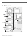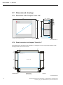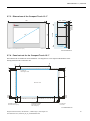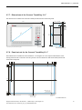
1
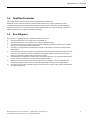
USER MANUAL 1.1 DPC3100 Industrial PC Copyright © Berghof Automation GmbH Reproduction and duplication of this document and utilisation and communication of its content is prohibited, unless with our express permission. All rights reserved. Damages will be payable in case of infringement. Disclaimer The content of this publication was checked for compliance with the hardware and software described. However, discrepancies may arise, therefore no liability is assumed regarding complete compliance. The information in this document will be checked regularly and all necessary corrections will be included in subsequent editions. Suggestions for improvements are always welcome. Subject to technical changes. Trademarks CANtrol® and CANtrol®- dialog are registered trademarks of Berghof Automation GmbH Microsoft®, Windows® and the Windows® Logo are registered trademarks of Microsoft Corporation in the USA and other countries. EtherCAT® is a registered trademark and patented technology, licensed from Beckhoff Automation GmbH, Germany. CiA® and CANopen® are registered community trademarks of CAN in Automation e.V. All rights reserved by the individual copyright holders. Content Completeness General Information on this Manual This equipment manual contains product-specific information valid at the time of publication. This equipment manual is only complete in conjunction with the product-related hardware and software user manuals required for the individual application. You can reach us at: Berghof Automation GmbH Harretstr. 1 72800 Eningen Germany T +49.7121.894-0 F +49.7121.894-100 e-mail: [email protected] www.berghof.com Berghof Automation GmbH works in accordance with DIN EN ISO 9001:2000. USER MANUAL 1.1 | DPC3100 Update Version Date Subject 1.1 03.04.2013 First Version Berghof Automation GmbH | Harretstrasse 1 | 72800 Eningen | www.berghof.com DPC3100_HB_en_2D1382001ZD00.docx 3 USER MANUAL 1.1 | DPC3100 Blank page 4 Berghof Automation GmbH | Harretstrasse 1 | 72800 Eningen | www.berghof.com DPC3100_HB_en_2D1382001ZD00.docx USER MANUAL 1.1 | DPC3100 Contents 1. GENERAL ..................................................................................................................................... 9 1.1. Scope of the manual .................................................................................................................... 9 1.2. About This Manual ....................................................................................................................... 9 1.3. Hazard Categories and Terminology ......................................................................................... 10 1.4. Qualified Personnel.................................................................................................................... 11 1.5. Due Diligence ............................................................................................................................. 11 1.6. Basic Safety Measures............................................................................................................... 12 1.7. Proper Use ................................................................................................................................. 13 1.8. Conformity Declaration .............................................................................................................. 13 1.8.1. CE Notice (European Union) ........................................................................................................ 13 1.9. Transport and Setup .................................................................................................................. 14 2. PRODUCT DESCRIPTION .......................................................................................................... 15 2.1.1. Interfaces..................................................................................................................................... 15 2.2. Identification .............................................................................................................................. 16 2.3. Technical data ............................................................................................................................ 18 2.4. Industrial PC construction ......................................................................................................... 20 2.4.1. Front view (Example 15" Connect-Key) ......................................................................................... 20 2.4.2. Rear view (Example 15" Connect-Key) ......................................................................................... 20 2.5. 2.5.1. 2.5.2. 2.5.3. Connections ............................................................................................................................... 21 Connector assignment ................................................................................................................. 21 Status indicators .......................................................................................................................... 21 External connections .................................................................................................................... 22 2.6. Block circuit diagram ................................................................................................................. 23 2.7. Dimensioned drawings .............................................................................................................. 24 2.7.1. Dimensions of the Compact Touch 10.4" ....................................................................................... 24 2.7.2. Panel cut-out for the Compact Touch 10.4" ................................................................................... 24 2.7.3. Dimensions of the Compact Touch 12.1" ....................................................................................... 25 2.7.4. Panel cut-out for the Compact Touch 12.1" ................................................................................... 25 2.7.5. Dimensions of the Compact Touch 15" .......................................................................................... 26 2.7.6. Panel cut-out for the Compact Touch 15" ...................................................................................... 26 2.7.7. Dimensions of the Connect Touch/Key 12.1" ................................................................................. 27 2.7.8. Panel cut-out for the Connect Touch/Key 12.1".............................................................................. 27 2.7.9. Dimensions of the Connect Touch/Key 15" .................................................................................... 28 2.7.10. Panel cut-out for the Connect Touch/Key 15" ................................................................................ 28 2.8. Mounting and installation .......................................................................................................... 29 2.8.1. Mounting...................................................................................................................................... 29 2.8.2. Connection .................................................................................................................................. 30 2.9. Pin assignment .......................................................................................................................... 31 2.9.1. Power supply ............................................................................................................................... 31 2.9.2. PS/2; keyboard .................................................................................................................... 31 2.9.3. 10/100 Base-T Network connection (Ethernet )..................................................................... 32 Berghof Automation GmbH | Harretstrasse 1 | 72800 Eningen | www.berghof.com DPC3100_HB_en_2D1382001ZD00.docx 5 USER MANUAL 1.1 | DPC3100 2.9.4. 10/100/1000 Base-T Network connection (Ethernet 2.9.5. 2.9.6. 2.9.7. 2.9.8. USB 1+2 and USB 3+4 ...................................................................................................... 33 CAN............................................................................................................................................. 34 COM1 and COM2 IOIOI............................................................................................................... 35 Optional COM3 and COM4 IOIOI ................................................................................................. 35 2.9.9. Optional VGA 3. ) ............................................................ 33 ....................................................................................................................... 36 OPERATING THE INDUSTRIAL PC............................................................................................. 37 3.1. Commissioning .......................................................................................................................... 37 3.1.1. Driver installation and initial startup ............................................................................................... 37 3.2. Decommissioning ...................................................................................................................... 38 3.2.1. Disposal ....................................................................................................................................... 38 3.3. Upkeep........................................................................................................................................ 38 3.4. Help in case of faults.................................................................................................................. 39 4. MAINTENANCE........................................................................................................................... 41 4.1. Opening the housing .................................................................................................................. 42 4.2. 4.2.1. 4.2.2. 4.2.3. 4.2.4. Motherboard ............................................................................................................................... 43 Internal connection ....................................................................................................................... 43 Mounting PC/104+ cards .............................................................................................................. 43 Battery replacement ..................................................................................................................... 44 CF card replacement .................................................................................................................... 44 4.3. Display........................................................................................................................................ 45 5. CHEMICAL RESISTANCE ........................................................................................................... 47 5.1. Resistance of the touch screen ................................................................................................. 47 5.2. 5.2.1. 5.2.2. 5.2.3. Resistance of the AUTOTEX front foil sheeting to chemicals ................................................... 48 General resistance of the foil sheeting material.............................................................................. 48 Resistance to household chemicals .............................................................................................. 49 Environmental values ................................................................................................................... 49 5.3. 5.3.1. 5.3.2. 5.3.3. Resistance of the AUTOFLEX- front foil sheeting to chemicals ................................................ 50 General resistance of the foil sheeting material.............................................................................. 50 Resistance to household chemicals .............................................................................................. 51 Outdoor use ................................................................................................................................. 51 6. ANNEX ........................................................................................................................................ 53 6.1. Environmental Protection .......................................................................................................... 53 6.1.1. Emission ...................................................................................................................................... 53 6.1.2. Disposal ....................................................................................................................................... 53 6.2. Maintenance/Upkeep .................................................................................................................. 53 6.3. Repairs/Service .......................................................................................................................... 53 6.3.1. Warranty ...................................................................................................................................... 53 6.4. Nameplate................................................................................................................................... 54 Nameplate descriptions (example) ................................................................................................ 54 6.5. Addresses and Bibliography...................................................................................................... 55 6.5.1. Addresses .................................................................................................................................... 55 6 Berghof Automation GmbH | Harretstrasse 1 | 72800 Eningen | www.berghof.com DPC3100_HB_en_2D1382001ZD00.docx USER MANUAL 1.1 | DPC3100 6.5.2. Standards/Bibliography ................................................................................................................ 56 Berghof Automation GmbH | Harretstrasse 1 | 72800 Eningen | www.berghof.com DPC3100_HB_en_2D1382001ZD00.docx 7 USER MANUAL 1.1 | DPC3100 Blank page 8 Berghof Automation GmbH | Harretstrasse 1 | 72800 Eningen | www.berghof.com DPC3100_HB_en_2D1382001ZD00.docx USER MANUAL 1.1 | DPC3100 1. General Documentation This equipment manual is intended for qualified personnel and contains information regarding the mounting, installation, commissioning and maintenance of the Industrial PC. The information contained in this manual is subject to change without prior notice. 1.1. Scope of the manual This manual applies to PCs of the DPC31XX T/K [CP] AT1.6 series. 1.2. About This Manual This equipment manual is an integral part of the product. Make sure the equipment manual is always available near the product’s point-of-employment. The manual contains information about the following topics: Areas of application Safety Mechanical construction Electrical construction Connections Commissioning Care and maintenance Decommissioning Disposal Berghof Automation GmbH | Harretstrasse 1 | 72800 Eningen | www.berghof.com 2VF100160FE01.docx | DPC3100_HB_en_2D1382001ZD00.docx 9 USER MANUAL 1.1 | DPC3100 1.3. Hazard Categories and Terminology DANGER Immediate danger. Failure to observe the information indicated by this warning will result in death, serious injury or extensive property damage. WARNING Potential danger. Failure to observe the information indicated by this warning may result in death, serious injury or extensive property damage. CAUTION Danger. Failure to observe the information indicated by this warning may result in injury or property damage. NOTICE No hazard. Information indicated in this manner provides additional notes concerning the product. 10 Berghof Automation GmbH | Harretstrasse 1 | 72800 Eningen | www.berghof.com DPC3100_HB_en_2D1382001ZD00.docx | 2VF100160FE01.docx USER MANUAL 1.1 | DPC3100 1.4. Qualified Personnel Only qualified personnel may install, operate and maintain the Industrial PC. Within the context of this documentation and the safety information it contains, qualified personnel constitutes trained specialists who have the authority to mount, install, commission, ground and identify equipment, systems and power circuits in accordance with the standards of safety technology, and who are familiar with the safety concepts of automation technology. 1.5. Due Diligence The operator or original equipment manufacturer (OEM) must ensure … That the Industrial PC is only employed for its intended use. That the Industrial PC is only employed in a fault-free, operational state. That the equipment manual is always maintained in a complete and legible condition and is available at the point-of-employment of the Industrial PC. That only properly qualified and authorized personnel mount, install, commission and maintain the Industrial PC. That these specialists receive regular and ongoing instruction in all pertinent questions related to work safety and environmental protection and that they are familiar with the contents of the equipment manual, in particular, with the safety information it contains. That the equipment identifiers as well as safety and warning information ap-plied to the Industrial PC are not removed and that they are maintained in a legible condition. That all international, federal, state and local ordinances governing the control of machinery and equipment applicable at the location at which the Industrial PC is employed are complied with. That the users always have available all relevant information they require with regard to the Industrial PC and its employment. Berghof Automation GmbH | Harretstrasse 1 | 72800 Eningen | www.berghof.com 2VF100160FE01.docx | DPC3100_HB_en_2D1382001ZD00.docx 11 USER MANUAL 1.1 | DPC3100 1.6. Basic Safety Measures Working on the PC Before beginning work on the Industrial PC you must always First ensure that the equipment is in a safe state. Then first switch the PC off, followed by the equipment, and Only then disconnect the PC from the equipment. WARNING Hazards due to unforeseeable functional and processing movements when the Industrial PC is disconnected. These can result in death, serious injury or extensive property damage. HAZARDOUS PROCESSES All equipment components must be disconnected from the Industrial PC whenever the Industrial PC is not being used for operational or control purposes, e.g., during maintenance or during functional checks after repairs. Lock out and tag out all equipment components after they have been switched off! Switching the PC off Before switching the Industrial PC off, make sure all programs have been properly exited. The Industrial PC must always be shut down normally. CAUTION Use the standard procedures to exit any software running on the Industrial PC. Failure to do so can result in data loss and damage to components. DATA LOSS Only switch the Industrial PC off once all running software has properly shut down. Opening the PC The supply voltage must be switched off before opening the housing or when installing or removing components. To do this, switch the power supply to the Industrial PC off. Then remove the plug from the power supply socket on the Industrial PC. WARNING Do not open the housing cover with the power switched on! Hazard due to contact with live components. This can result in death, serious injury or extensive property damage. HAZARDOUS VOLTAGE 12 Only open the housing cover once the Industrial PC has been safely disconnected from the power supply. Berghof Automation GmbH | Harretstrasse 1 | 72800 Eningen | www.berghof.com DPC3100_HB_en_2D1382001ZD00.docx | 2VF100160FE01.docx USER MANUAL 1.1 | DPC3100 1.7. Proper Use The Industrial PC is designed as an OEM*) component for further integration into industrial equipment, machinery and systems. The Industrial PC is used to operate a controller. It therefore performs functions not directly related to safety. The Industrial PC is designed for use within overvoltage category I (IEC 364-4-443) to operate machinery, equipment and industrial processes in low-voltage equipment in which the designated supply voltage does not exceed 1,000 V AC (50/60 Hz) or 1,500 V DC. NOTICE This Industrial PC has not been approved for use in explosion hazard areas. This Industrial PC is intended for employment in a typical Class A industrial environment. Limit value requirements in accordance with EN 55011 provide for two classifications: Class A for typical industrial environments. Class B for typical domestic environments. Fault-free and safe operation of the Industrial PC requires qualified project planning, proper transport, storage, setup and use, as well as careful maintenance and upkeep. The Industrial PC may only be employed within the context of the data specifications and applications defined in this equipment manual. Any other employment is deemed to represent improper use. Unauthorized modifications or alterations not described in this equipment manual are prohibited. *) OEM = Original Equipment Manufacturer 1.8. Conformity Declaration 1.8.1. CE Notice (European Union) Identification by the CE symbol indicates that this Industrial PC complies with the EMC guidelines and the low-voltage guidelines of the European Union. It further indicates compliance with the following technical standards: EN 55011:2007 Industrial, scientific and medical (ISM) radio-frequency Equipment Electromagnetic disturbance characteristics - Limits and methods of measurement, Class A EN 61326-1:2008-6 Electrical Equipment for Measurement, Control and Laboratory Use – EMC Requirements 1.) DC connections between parts of devices or systems which are not connected up to a DC supply mains. 2.) USB and printer connector cords < 3 m 3.) Set shielding bilaterally, shielded cables Berghof Automation GmbH | Harretstrasse 1 | 72800 Eningen | www.berghof.com 2VF100160FE01.docx | DPC3100_HB_en_2D1382001ZD00.docx 13 USER MANUAL 1.1 | DPC3100 1.9. Transport and Setup NOTICE Please note the specified storage conditions in the section ‘Technical Specifications’. Transport Protect the Industrial PC against extreme mechanical stress during transport. Always transport the Industrial PC in its original packaging. The built-in components are extremely sensitive to jarring and strong vibrations. CAUTION Condensation hazard resulting from climatic fluctuations. Risk of damage as a result of moisture forming on or in the Industrial PC (condensation). This can result in destruction of the device or consequential damages. CONDENSATION After storage or transport in cold weather or under conditions of strongly fluctuating temperatures, the Industrial PC must be allowed to slowly adjust to the ambient temperature at its point of use before it can be taken into service. In case of condensation, the unit may not be taken into service for at least 12 hours (temperature compensation). Unpacking Proceed as follows: Inspect the packaging for any external damage. If the packaging is severely damaged or if damage to the contents can be detected, do not open the packaging any further. Immediately contact your shipper and your supplier. Remove the packaging. Do not discard the original packaging! The packaging can be used for subsequent transport. Inspect the contents for visible shipping damage. Check the contents against the order for completeness. Save all included documentation. This documentation contains important information concerning the Industrial PC and is an integral part of the product. If shipping damage is detected or if the received contents do not agree with the order, please contact your supplier immediately. Setup This Industrial PC is designed for installation in fully enclosed circuit cabinets of industrial machinery and equipment. When installing the Industrial PC, take particular care to ensure that the included seal profiles are not damaged. Also ensure compliance with the ambient conditions specified under ‘Technical Specifications’. 14 Berghof Automation GmbH | Harretstrasse 1 | 72800 Eningen | www.berghof.com DPC3100_HB_en_2D1382001ZD00.docx | 2VF100160FE01.docx USER MANUAL 1.1 | DPC3100 2. Product description Short description The IBM-compatible Industrial PCs of the DPC3100 series are designed for front panel or circuit cabinet installation in harsh industrial environments. The fan-free design and flash memory (hard disk optional) keep maintenance expenditures to a minimum. Depending on the computing power required by the application, the DPC31XX can be equipped with a variety of processors. A wide performance spectrum ranging from a simple geode processor offering 500 MHz up to an Intel® Atom™1.6 GHZ is available. The DPC31XX has a 10, 12 or 15” TFT display. The housing dimensions and protective class (IP65 on the front) are identical on units of the ‘Connect’ series with either a touch screen or matrix keyboard. The ‘Compact’ series feature reduced mounting dimensions and is only available as touch screen. 2.1.1. Interfaces Ethernet Two Ethernet interfaces (1x 10/100 MBit/s, 1x 10/100/1000 MBit/s) are available. Thanks to the TCP/IP and UDP/IP protocols it is possible to link it very variably to visualisation software, to higher order control units or to the IT infrastructure. USB The max. 4+2 USB host interfaces provide a widely-used peripheral interface. For example it can be used to carry out an application update or data migration simply via a USB stick. CAN Interfaces The Industrial PC possesses 1 standard CAN interface which can be used up to 1 Mbit/s. Serial Interfaces There are two serial RS232 interfaces on the Industrial PC. Optionally, 2 RS422 interfaces can be realized with an additional card. Those are implemented as USB-toRS422 interfaces by a Prolific-IC. Driver support is available for (embedded) Windows XP. Please contact our Technical Support for other OS. PC/104+ It is possible to plug in a PC104 card for the Connect DPC. For that the 02 type is necessary. Berghof Automation GmbH | Harretstrasse 1 | 72800 Eningen | www.berghof.com 2VF100161FE01.docx | DPC3100_HB_en_2D1382001ZD00.docx 15 USER MANUAL 1.1 | DPC3100 2.2. Identification Product: Industrial PC, Type DPC3115 Nameplate 2VF100431DG00.cdr Identification key Connect series Using the identification key, the characteristics of the Industrial PC can be decoded as follows (refer to the nameplate). 1 2 3 4 5 6 7 D P C 3 1 1 5 8 9 T 10 11 12 13 14 15 16 17 18 19 ... 0 1 G E Diagonal screen size In Inch Clock frequency 500 = 500 MHz 1.6 = 1.6 GHZ (rounded value) Activation method T = Touchpanel K = Keyboard A = All (Touch + Keyboard) 0 0 Processor type GE = Geode AT = ATOM Design height 01 = 1 Plug line no PC104 possible 02 = 2 Plug lines 1x PC104 possible 2VF100422DG01.cdr 16 Berghof Automation GmbH | Harretstrasse 1 | 72800 Eningen | www.berghof.com DPC3100_HB_en_2D1382001ZD00.docx | 2VF100161FE01.docx USER MANUAL 1.1 | DPC3100 Identification key Compact series Using the identification key, the characteristics of the Industrial PC can be decoded as follows (refer to the nameplate). 1 2 3 4 5 6 7 8 D P C 3 1 1 5 9 T 10 11 12 13 14 15 16 17 18 19 20 21 22 ... C P 0 1 G E 0 0 Diagonal screen size In Inch Clock frequency 500 = 500 MHz 1.6 = 1.6 GHZ (rounded value) Processor type GE = Geode AT = ATOM Activation method T = Touchpanel Compact series CP = without front USB Design height 01 = 1 Plug line, no PC104 possible 02 = 2 Plug lines, 1x PC104 possible 2VF100423DG01.cdr Berghof Automation GmbH | Harretstrasse 1 | 72800 Eningen | www.berghof.com 2VF100161FE01.docx | DPC3100_HB_en_2D1382001ZD00.docx 17 USER MANUAL 1.1 | DPC3100 2.3. Technical data Industrial PC Compact series DPC31XX Type Compact-Touch Display 10.4" 12.1" 15" Designation DPC3110 T CP DPC3112 T CP DPC3115 T CP Dimensions (WxHxD [mm]) incl. front panel (01/02) 330 x 260 x 115/130 360 x 260 x 115/130 400 x 310.3 x 115/130 Installation depth [mm] (01/02) 110/125 110/125 110/125 Weight [kg] Approx. 5 Approx. 6 Approx. 7 Connect series DPC31XX Type Connect-Touch / Connect-Key Display 12.1" 15" Designation DPC3112 T/K DPC3115 T/K Dimensions (WxHxD [mm]) incl. front panel (01/02) 440 x 300 x 115/130 482,6 x 310.3 x 115/130 Installation depth [mm] (01/02) 110/125 110/125 Weight [kg] ca. 6.5 ca. 7.5 Operating conditions Ambient temperature 0°C to 50°C for DPC with touchscreen: 0°C to 35 °C max. 90 % relative air humidity 35°C to 50 °C max. 50 % relative Humidity max. 90 %, non-condensating Resistance to vibrations Vibration sinus-shaped (EN 60068-2-6) test: Fc 10 ... 150 Hz, 1 G (Operation Mode) Shock resistance 15 G (approx. 150 m/s²), 10 ms duration, semi-sinus (EN 60068-2-27) test: Ea Protection class Protection class IP20 (front panel, IP65) Power supply (24 V power pack) 18 Supply voltage +24 VDC (-15% /+20%) SELV, max. AC component 5% Current consumption typ. 1-1.5 A with +24 VDC, max. 2.0 A Expansion card: max. current consumption via PC104+ at +5 VDC = 2 A at +12 VDC = 1 A. Berghof Automation GmbH | Harretstrasse 1 | 72800 Eningen | www.berghof.com DPC3100_HB_en_2D1382001ZD00.docx | 2VF100161FE01.docx USER MANUAL 1.1 | DPC3100 Industrial PC Compatibility Electromagnetic resistance / emission EN 61326-1:2008-6 Interfaces Ethernet 1x 10/100 Base T 1x 10/100/1000 Base T USB 4x USB Rev. 2.0 (on rear) 2x USB Rev. 2.0 (on the front, optional) CAN-Bus 1x Standard CAN ISO 11898 Serial 2x RS232 C (COM1 / COM2) RS422/485 SUB-D9 (optional) PS/2 for touch PC: external keyboard only (not hot plug-capable) for keyboard PC: mouse + keyboard via Y-Kabel ((not hot plugcapable)) VGA 1x optional VGA connection Transport, storage Humidity Same values as listed under ‘Ambient conditions’. Vibration resistance Vibration resistance can be increased by appropriate transport packaging. Ambient temperature -25°C to +60°C; für DPC with touchscreen: -25°C to 0°C, and 35°C to 60 °C max. 40 % relative humidity 0°C to 35°C max. 90 % relative humidity Berghof Automation GmbH | Harretstrasse 1 | 72800 Eningen | www.berghof.com 2VF100161FE01.docx | DPC3100_HB_en_2D1382001ZD00.docx 19 USER MANUAL 1.1 | DPC3100 2.4. Industrial PC construction 2.4.1. Front view (Example 15" Connect-Key) USB 3 USB 4 2VF100179DG00.cdr 2.4.2. Rear view (Example 15" Connect-Key) Connections Front panel 2VF100428DG01.cdr 20 Berghof Automation GmbH | Harretstrasse 1 | 72800 Eningen | www.berghof.com DPC3100_HB_en_2D1382001ZD00.docx | 2VF100161FE01.docx USER MANUAL 1.1 | DPC3100 2.5. Connections 2.5.1. Connector assignment Option VGA (Sub-HD-15 ) X 41 COM2 (RS232 C) Option COM3+4 (RS422, Plug line 02) X 42 COM1 (RS232 C) X 27 USB2 + USB1 (Rev.2.0) X 15 10/100/1000 Base-T (Network) X 31 10/100 Base-T (Network) X 28 USB4 + USB3 (Rev.2.0) X 16 PS/2 (Keyboard, mouse) X 19 CAN X 26 Power supply (24 VDC) Option PC/104+ (Extension for case 02) 2VF100429DG01.cdr 2.5.2. Status indicators LED green ready LED green orange 100 1000 LED yellow Data Receive LED yellow LINK 2VF100430DG01.cdr Berghof Automation GmbH | Harretstrasse 1 | 72800 Eningen | www.berghof.com 2VF100161FE01.docx | DPC3100_HB_en_2D1382001ZD00.docx 21 USER MANUAL 1.1 | DPC3100 2.5.3. External connections NOTICE Connecting other devices Before connecting any peripheral device, please read the device’s associated documentation. When connecting or disconnecting cords, always hold them by their plugs. Never pull on the cords themselves! Connection points for all external connections are located on the back of the Industrial PC. All connections are plug-in type connections. X26 X19 X16 X28 X31 X15 X27 Option PC/104+ X42 X41 Option VGA 2VF100432DG01.cdr 22 Berghof Automation GmbH | Harretstrasse 1 | 72800 Eningen | www.berghof.com DPC3100_HB_en_2D1382001ZD00.docx | 2VF100161FE01.docx USER MANUAL 1.1 | DPC3100 2.6. Block circuit diagram Touchglas Inverter LP Status-LED Display USB optional USB 2x USB 2.0 FRONT RS232 X42 ETX-Board ETX Grafik RS232 X41 Ethernet ETX CompactFlash CPU IDE RAM steckbar/pluggable Touch controller PS/2 ISA X16 X15 10/100/1000 Base-T EthernetTransceiver X31 10/100 Base-T X27 USB X28 USB EthernetTransceiver 4x USB 2.0 DPM PCI Serial EEPROM VGA optional optional LPT, COM ETX Controller CAN HW-Monitor Tastaturmatrix + Weiche Keyboard matrix + separating filter Ethernet USB CAN Transceiver X19 USB optional RS422 Prolific DC X26 DC USB + 3,3 VDC + 5 VDC Mi + 12 VDC USB Flash-Modul (optional) BASIS 2VF100421DG00.cdr Berghof Automation GmbH | Harretstrasse 1 | 72800 Eningen | www.berghof.com 2VF100161FE01.docx | DPC3100_HB_en_2D1382001ZD00.docx 23 USER MANUAL 1.1 | DPC3100 2.7. Dimensioned drawings 2.7.1. Dimensions of the Compact Touch 10.4" 330 max. 110/125 6 , 4” 260 10 226,50 Gewindebolzen threaded bolt M4 x 16 mm 16 Freie Luftzirkulation free air circulation Freiraum / clearance > 20 mm Alle Maße in [mm] / All dimensions in [mm] DPC3110 T 2VF100433DG00.cdr 2.7.2. Panel cut-out for the Compact Touch 10.4" 0 10 16,75 290 40 0 The Industrial PC is intended for front installation. A rectangular cut-out is required. The thickness of the bearing material must not exceed 6 mm. 0 10 16,75 6 x Ø 5 mm Bohrungen / drills DPC3110 T CP 130 130 290 Fronttafel-Ausschnitt Front panel cut out 296,50 x 226,50 [mm] 313,25 320 330 Alle Maße in [mm] All dimensions in [mm] 40 243,25 250 260 0 10 16,75 243,25 250 260 Frontansicht Front view 2VF100424DG00.cdr 24 Berghof Automation GmbH | Harretstrasse 1 | 72800 Eningen | www.berghof.com DPC3100_HB_en_2D1382001ZD00.docx | 2VF100161FE01.docx USER MANUAL 1.1 | DPC3100 2.7.3. Dimensions of the Compact Touch 12.1" 360 max. 110/125 6 ” ,1 260 12 226,50 Gewindebolzen threaded bolt M4 x 16 mm 16 Freie Luftzirkulation free air circulation Freiraum / clearance > 20 mm Alle Maße in [mm] / All dimensions in [mm] DPC3112 T 2VF100434DG00.cdr 2.7.4. Panel cut-out for the Compact Touch 12.1" 0 40 280 The Industrial PC is intended for front installation. A rectangular cut-out is required. The thickness of the bearing material must not exceed 6 mm. 0 10 14 0 10 14 6 x Ø 5 mm Bohrungen / drills 80 DPC3112 T CP 246 250 260 Alle Maße in [mm] All dimensions in [mm] Fronttafel-Ausschnitt Front panel cut out 332 x 232 [mm] 346 350 360 320 180 40 14 0 246 250 260 Frontansicht Front view 2VF100425DG00.cdr Berghof Automation GmbH | Harretstrasse 1 | 72800 Eningen | www.berghof.com 2VF100161FE01.docx | DPC3100_HB_en_2D1382001ZD00.docx 25 USER MANUAL 1.1 | DPC3100 2.7.5. Dimensions of the Compact Touch 15" 400 max. 110/125 6 ” 284 15 310,30 (7 HE) Gewindebolzen threaded bolt M4 x 16 mm 16 Freie Luftzirkulation free air circulation Freiraum / clearance > 20 mm Alle Maße in [mm] / All dimensions in [mm] DPC3115 T 2VF100435DG00.cdr 2.7.6. Panel cut-out for the Compact Touch 15" 0 8,50 13 325 75 0 The Industrial PC is intended for front installation. A rectangular cut-out is required. The thickness of the bearing material must not exceed 6 mm. 0 8,50 13 6 x Ø 5 mm Bohrungen /drills 155 155 DPC3115 T CP 297 301,50 310 325 Fronttafel-Ausschnitt Front panel cut out 371 x 284 [mm] 385,50 390 400 Alle Maße in [mm] All dimensions in [mm] 75 0 10 14,50 297 301,50 310 Frontansicht Front view 2VF100426DG00.cdr 26 Berghof Automation GmbH | Harretstrasse 1 | 72800 Eningen | www.berghof.com DPC3100_HB_en_2D1382001ZD00.docx | 2VF100161FE01.docx USER MANUAL 1.1 | DPC3100 2.7.7. Dimensions of the Connect Touch/Key 12.1" The dimensions are identical for both units with keyboards and units with touch panels. 440 max. 110/125 6 8 9 4 5 6 S3 1 2 3 S4 0 . _ Shift Ctrl Enter S5 1 S6 1" 2, Pos1 S7 270 7 S2 300 S1 Gewindebolzen threaded bolt M4 x 16 mm 16 PgUp S8 BkSp PgDn S9 S10 F1 F2 F3 F4 F5 F6 F7 F8 F9 F10 F11 F12 Freie Luftzirkulation free air circulation Freiraum / clearance > 20 mm Alle Maße in [mm] / All dimensions in [mm] DPC3112 K 2VF100436DG00.cdr 2.7.8. Panel cut-out for the Connect Touch/Key 12.1" 426 430 440 400 360 220 40 0 10 14 The Industrial PC is intended for front installation. A rectangular cut-out is required. The thickness of the bearing material must not exceed 6 mm. The panel cut-outs are identical for both units with keyboards and units with touch panels. 0 10 14 150 DPC3112 K Bohrungen / drills Ø 5 mm (8x) 286 290 300 Alle Maße in [mm] / All dimensions in [mm] Fronttafel-Ausschnitt Front panel cut out Frontansicht Front view 412 x 272 [mm] 2VF100437DG00.cdr Berghof Automation GmbH | Harretstrasse 1 | 72800 Eningen | www.berghof.com 2VF100161FE01.docx | DPC3100_HB_en_2D1382001ZD00.docx 27 USER MANUAL 1.1 | DPC3100 2.7.9. Dimensions of the Connect Touch/Key 15" The dimensions are identical for both units with keyboards and units with touch panels. 482,6 (19") max. 110/125 6 8 9 4 5 6 S3 1 2 3 S4 0 . _ Shift Ctrl Enter S5 S6 " 15 S7 Pos1 PgUp S8 BkSp 280 7 S2 310,3 (7HE) S1 Gewindebolzen threaded bolt M4 x 16 mm 16 PgDn S9 S10 S11 S12 F1 F2 F3 F4 F5 F6 F7 F8 F9 F10 F11 F12 F13 F14 Freie Luftzirkulation free air circulation Freiraum / clearance > 20 mm F15 Alle Maße in [mm] / All dimensions in [mm] DPC3115K 2VF100438DG00.cdr 2.7.10. Panel cut-out for the Connect Touch/Key 15" 468 473 482 0 9 14 241 The Industrial PC is intended for front installation. A rectangular cut-out is required. The thickness of the bearing material must not exceed 6 mm. The panel cut-outs are identical for both units with keyboards and units with touch panels. 0 10 14 38,5 DPC3115 K Bohrungen / drills Ø 5 mm (6x) 271,5 296 300 310 Alle Maße in [mm] / All dimensions in [mm] Fronttafel-Ausschnitt Front panel cut out Frontansicht Front view 454 x 282 [mm] 2VF100439DG00.cdr 28 Berghof Automation GmbH | Harretstrasse 1 | 72800 Eningen | www.berghof.com DPC3100_HB_en_2D1382001ZD00.docx | 2VF100161FE01.docx USER MANUAL 1.1 | DPC3100 2.8. Mounting and installation 2.8.1. Mounting Required tools Allen key, socket wrench or open-end wrench SW, 7 mm (M4) Mounting The Industrial PC is equipped with 6 force fitted, M4 x approx. 16 mm threaded bolts. Number and order depend on the device type. For more details see section ‘Dimensioned drawings’. A secure mounting requires U washers, spring/lock washers and nuts (M 4). Remove the fastening nuts and washers from the bolts. Push the Industrial PC through the mounting cut-out. Secure the PC in the mounting cut-out. Adjust the PC in the mounting cut-out and tighten all nuts. 2VF100440DG00.cdr NOTICE Disassembly Disassembling/removing the Industrial PC occurs in reverse order. Berghof Automation GmbH | Harretstrasse 1 | 72800 Eningen | www.berghof.com 2VF100161FE01.docx | DPC3100_HB_en_2D1382001ZD00.docx 29 USER MANUAL 1.1 | DPC3100 2.8.2. Connection Power supply Power is supplied to the Industrial PC via an external 24 VDC power supply. Before connecting the external power supply, check to make sure it conforms to the required specifications below. External power supply (24 VDC) Output voltage +24 VDC SELV (-15% /+20%) Alternating current portion max. 5% The DC level must not drop below 20.4 V. Power output min. 2.0 A at +24 VDC at 25 °C (w/o PC104 expansion card) Installation All connections and wiring must be laid out to prevent any interference as a result of inductive or capacitive pick-ups in the Industrial PC. Input wiring must have adequate current and voltage resistance. Ground wire Connect the housing of the Industrial PC to the ground terminal (PE), copper lead cross-section min. 1.5 mm². PE nut lock washer thimble washer 2VF100441DG01.cdr 30 Berghof Automation GmbH | Harretstrasse 1 | 72800 Eningen | www.berghof.com DPC3100_HB_en_2D1382001ZD00.docx | 2VF100161FE01.docx USER MANUAL 1.1 | DPC3100 2.9. Pin assignment 2.9.1. Power supply Internal power pack The Industrial PC is equipped with an internal power pack for 24 VDC (19.2 V...30 V) input voltage. The power pack is equipped with built-in reverse polarity protection and a current at make limiter (5 A). The infeed and the power pack must be protected by an external short circuit and overload protector with an activation current of 6 A. 24 V power pack output voltages Maximum current load +5V 7A + 12 V 2.5 A X26 pin assignment X26 Phoenix MSTB 2.5/2-G-5.08 Außen Innen 1 external 24 VDC (18 V...30 V) power supply 2 external power supply GND 2.9.2. PS/2; keyboard CAUTION PS/2 is not hot plug-capable. If a PS/2 keyboard is connected during operation the touch screen and/or the keyboard may crash. X16 pin assignment X16 Min-D6 1 KBDAT 2 MSDAT; only on 'K' (keyboard) version 3 GND 4 VCC 5 KBCLK 6 MSCLK; only on 'K' (keyboard) version Berghof Automation GmbH | Harretstrasse 1 | 72800 Eningen | www.berghof.com 2VF100161FE01.docx | DPC3100_HB_en_2D1382001ZD00.docx 31 USER MANUAL 1.1 | DPC3100 NOTICE A Y cable is required to use the PS/2 mouse with version DPC31XXK. PS/2: for touch PC external keyboard only, for keyboard PC mouse and keyboard via Y cable 2.9.3. 10/100 Base-T Network connection (Ethernet ) The on-board 10/100 Base-T Ethernet adapter with an RJ-45 connection is used to establish the network link.The length of the cable depends on the ETX module used (tested for 50 m). For more details please refer to the ETX-Board (CPU board) manual. X31 pin assignment X31 1 TX+ 2 TX- 3 RX+ 4 75 Ohm 5 75 Ohm 6 RX- 7 75 Ohm 8 75 Ohm LED green ON – operational LED yellow FLASHING – Data Receive RJ45 32 10/100 Berghof Automation GmbH | Harretstrasse 1 | 72800 Eningen | www.berghof.com DPC3100_HB_en_2D1382001ZD00.docx | 2VF100161FE01.docx USER MANUAL 1.1 | DPC3100 2.9.4. 10/100/1000 Base-T Network connection (Ethernet ) The on-board 10/100/1000 Base-T Ethernet adapter with an RJ-45 connection is used to establish the network link.The length of the cable depends on the ETX module used (tested for 50 m). For more details please refer to the ETX-Board (CPU board) manual. X15 pin assignment X15 10/100/1000 1 MX0+ 2 MX0- 3 MX1+ 4 MX1- 5 MX2+ 6 MX2- 7 MX3+ 8 MX3- LED green orange 100 1000 LED yellow LINK RJ45 2.9.5. USB 1+2 and USB 3+4 USB Ports (Rev. 2.0) X27 and X28 pin assignment X27 and X28 USB 2 USB 1 USB 4 USB 3 B1 VCC B2 D- B3 D+ B4 GND Berghof Automation GmbH | Harretstrasse 1 | 72800 Eningen | www.berghof.com 2VF100161FE01.docx | DPC3100_HB_en_2D1382001ZD00.docx 33 USER MANUAL 1.1 | DPC3100 CAUTION The USB ports can provide a max. current of 0.5 A. A device requiring more current will not function and may therefore be damaged. Recommendation: Please use devices which have an internal power supply in this case. DAMAGE NOTICE Certain USB floppy drives may not be identified as the boot medium. Recommendation: Please use TEAC drives. The mechanical structure of the USB port is designed to max. 1000 mating cycles. NOTICE 2.9.6. CAN The CAN interface conforms to the ISO 11898 Standard. X19 pin assignment X19 6 9 NC 2 CAN_L 3 CAN_GND 4 NC 5 NC 6 NC 7 CAN_H 8 NC 9 NC 5 Sub-D9 M NOTICE 34 1 1 A terminating resistor for the CAN Bus can be connected with the switch S1 (see section ‘Motherboard’, ‘Internal connection’). Berghof Automation GmbH | Harretstrasse 1 | 72800 Eningen | www.berghof.com DPC3100_HB_en_2D1382001ZD00.docx | 2VF100161FE01.docx USER MANUAL 1.1 | DPC3100 2.9.7. COM1 and COM2 IOIOI Serial interfaces (COM1 / COM2) in accordance with RS232C X42 (COM1) and X41 (COM2) pin assignment X42 / X41 6 9 1 DCD 2 RXD 3 TXD 4 DTR 5 GND 6 DSR 7 RTS 8 CTS 9 RI 1 5 Sub-D9 M 2.9.8. Optional COM3 and COM4 IOIOI Serial interfaces (COM3 / COM4) in accordance with RS422 COM3 and COM4 pin assignment 6 9 1 Not used 2 RXD- 3 TXD- 4 Not used 5 GND 6 Not used 7 TXD+ 8 RXD+ 9 Not used 1 5 Sub-D9 M NOTICE COM3 and COM4 are implemented as RS422 interfaces. Conversion USB-to-Seriell ensues on the I/O board. In addition you find the Prolific driver in the device manager. Berghof Automation GmbH | Harretstrasse 1 | 72800 Eningen | www.berghof.com 2VF100161FE01.docx | DPC3100_HB_en_2D1382001ZD00.docx 35 USER MANUAL 1.1 | DPC3100 2.9.9. Optional VGA VGA (optional) not for devices of the Compact series Pin assignment Sub-HD-15F 36 1 VGA_R 2 VGA_G 3 VGA_B 4 NC 5 GND 6 GND 7 GND 8 GND 9 NC 10 GND 11 NC 12 DDDA 13 VGA_H 14 VGA_V 15 DDCK Berghof Automation GmbH | Harretstrasse 1 | 72800 Eningen | www.berghof.com DPC3100_HB_en_2D1382001ZD00.docx | 2VF100161FE01.docx USER MANUAL 1.1 | DPC3100 3. Operating the Industrial PC 3.1. Commissioning 3.1.1. Driver installation and initial startup The Industrial PC can be delivered with a preinstalled copy of the Linux XP embedded or XP Professional operating system. All hardware drivers required for the existing equipment are installed. Remove battery protection You must remove the battery protection before switching on for the first time! To do so, first slide off the flexible insulating tubing towards the front. The battery is located on the motherboard. Please also refer to the 'Motherboard' section. Battery protection 2VF100393DG01.cdr Power on The Industrial PC is not equipped with its own mains power switch. The Industrial PC starts when the equipment is switched on or when the power supply is connected. Switching off CAUTION Use the standard procedures to exit any software running on the Industrial PC. Failure to do so can result in data loss and damage to components. DATA LOSS Only switch the Industrial PC off once all running software has properly shut down. The Industrial PC is switched off when the equipment is switched off or the power supply is shut down Before switching the Industrial PC off, make sure all programs have been properly exited. The Industrial PC must always be shut down normally. NOTICE Software typically employed on the Industrial PC allows various users to be assigned different access privileges. Those users with no privileges to exit software are therefore also not permitted to switch the Industrial PC off. Berghof Automation GmbH | Harretstrasse 1 | 72800 Eningen | www.berghof.com 2VF100162FE01.docx | DPC3100_HB_en_2D1382001ZD00.docx 37 USER MANUAL 1.1 | DPC3100 3.2. Decommissioning 3.2.1. Disposal Disassembly The Industrial PC must be completely disassembled into its component parts for disposal. All metal components can be disposed of as recyclable metal waste. Electronic scrap All electronic components such as PCBs, drives, etc. must be sorted for disposal. Specifics concerning disposal are regulated by federal, state and local ordinances. Compliance with these is mandatory. Battery CAUTION Batteries contain materials which are hazardous to health and to the environment. Batteries may only be disposed of through authorized channels. HAZARDOUS MATERIAL EMISSIONS Make sure the battery is fully discharged. If necessary, protect the contacts against short circuiting with a strip of insulating tape. 3.3. Upkeep Cleaning In order to prevent faults due to accidental activation, the Industrial PC must be switched off when the front panel is cleaned. CAUTION Use the standard procedures to exit any software running on the Industrial PC. Failure to do so can result in data loss and damage to components. DATA LOSS Only switch the Industrial PC off once all running software has properly shut down. Use a moistened, clean, soft, lint-free cloth to clean the front of the Industrial PC. Please observe the following to prevent damaging the front panel during cleaning: Never use high-pressure or steam cleaners. Never use caustic cleansers, solvents, abrasives or hard objects when cleaning. Do not apply excessive pressure to the front panel when cleaning. 38 Berghof Automation GmbH | Harretstrasse 1 | 72800 Eningen | www.berghof.com DPC3100_HB_en_2D1382001ZD00.docx | 2VF100162FE01.docx USER MANUAL 1.1 | DPC3100 3.4. Help in case of faults Please read the section, ‘Basic Safety Measures’. If the actions described below are unsuccessful, please contact your supplier’s service department. Fault Possible cause Recommended corrective actions No function when the Industrial PC is started. No power to the Industrial PC. Make sure the power supply cable is plugged in. Check the pin assignment for a polarity reversal. Check (measure) the connection voltage. The Industrial PC fails to completely boot up. Compact Flash faulty (CF card). Replace the faulty CF card with a new one if one is available. Incorrect SETUP settings. Check the SETUP settings (Boot Device Priority). USB medium not bootable. Remove USB. Display shows nothing, external monitor OK. Faulty SETUP settings. Check SETUP display settings: 15"-XGA, 12.1"SVGA, 10.4"-VGA. LED display flickers. Operating voltage fluctuates between 17 and 18 VDC. Increase operating voltage, 19.2 VDC minimum. Berghof Automation GmbH | Harretstrasse 1 | 72800 Eningen | www.berghof.com 2VF100162FE01.docx | DPC3100_HB_en_2D1382001ZD00.docx 39 USER MANUAL 1.1 | DPC3100 Blank page 40 Berghof Automation GmbH | Harretstrasse 1 | 72800 Eningen | www.berghof.com DPC3100_HB_en_2D1382001ZD00.docx | 2VF100162FE01.docx USER MANUAL 1.1 | DPC3100 4. Maintenance Battery Use only VARTA CR2032 type batteries. The built-in battery must be replaced every 5 years at least. In the case of computers which are not connected to the power supply (non-operative) the battery capacity is sufficient for approximately 500 days (without protection of battery drain). Maintenance work Maintenance work on the Industrial PC, particularly work involving the opening of the housing, may only be performed by qualified personnel! Before beginning any maintenance work, please read the ‘General’ chapter, in particular, the ‘Basic Safety Measures’ section. WARNING Do not open the housing cover with the power switched on! Hazard due to contact with live components. This can result in death, serious injury or extensive property damage. HAZARDOUS VOLTAGE Only open the housing cover once the Industrial PC has been safely disconnected from the power supply. Maintenance work on the Industrial PC can result in damage if metal objects such as screws, nuts, tools, etc. fall on the PCB. if connecting cables are loosened, removed or incorrectly reconnected. After maintenance Before returning the Industrial PC to service, check to be sure that there are no foreign objects in the PC. there is a battery in the battery slot. all connections are correct and secure. the ground wire (PE) is properly connected. NOTICE Be sure all covers on the Industrial PC are closed before returning the PC to service! Berghof Automation GmbH | Harretstrasse 1 | 72800 Eningen | www.berghof.com 2VF100163FE01.docx | DPC3100_HB_en_2D1382001ZD00.docx 41 USER MANUAL 1.1 | DPC3100 4.1. Opening the housing Tools are required to open the housing cover on the Industrial PC. Open the housing cover as follows: Loosen the 4 fastening screws (A). The screws are captive (M4/PH1 Philips head). Lift the housing cover and flip it open. Cover fastening screw A A Expand laterally Caution: Do not lever out the device! 2VF100442DG01.cdr Reassemble the housing cover in the reverse order. 42 Berghof Automation GmbH | Harretstrasse 1 | 72800 Eningen | www.berghof.com DPC3100_HB_en_2D1382001ZD00.docx | 2VF100163FE01.docx USER MANUAL 1.1 | DPC3100 4.2. Motherboard 4.2.1. Internal connection S1 CF card battery OFF / ON 2VF100432DG01.cdr NOTICE A terminating resistor for the CAN Bus (X19) can be connected resp. disconnected with the switch S1 (Right = ON). It is connected ex factory (see section ‘Product description’, ‘Pin assignment’, ‘CAN’). 4.2.2. Mounting PC/104+ cards 4x bolt (Item-No. 2T0760000) max. length of external screw thread: 3.5 mm 2VF100458DG01.cdr Berghof Automation GmbH | Harretstrasse 1 | 72800 Eningen | www.berghof.com 2VF100163FE01.docx | DPC3100_HB_en_2D1382001ZD00.docx 43 USER MANUAL 1.1 | DPC3100 CAUTION Please use only bolts of the Berghof company with the order number 2T0760000 for mounting the PC/104+ cards. The usage of other distance bolts may cause a damage of the hardware. DAMAGE 4.2.3. Battery replacement CAUTION Batteries contain materials which are hazardous to health and to the environment. Batteries may only be disposed of through authorized channels. Make sure the battery is fully discharged. HAZARDOUS MATERIAL EMISSIONS If necessary, protect the contacts against short circuiting with a strip of insulating tape. Battery type The battery is located on the motherboard. To replace the battery, open the tension tab on the battery holder and remove the battery. Replace the dead battery only with a round cell type VARTA CR2032. Make sure the polarity is correct when installing the new battery. 2VF100443DG00.cdr 4.2.4. CF card replacement CF card removal The CF card is located on the motherboard. To replace the CF card, open the locking tab on the CF card socket. Pull the locking tab forward and away from the CF card, then flip the tab up. Carefully hold the CF card on its long sides and gently jiggle the card while pulling it out of its socket. 2VF100444DG00.cdr CF card installation Install the new CF card in the reverse order. Make sure the CF card is properly positioned in the socket. The card is equipped with a reversal protection. Do not force the card into the socket. After installing the CF card, re-secure it with the locking tab. 44 Berghof Automation GmbH | Harretstrasse 1 | 72800 Eningen | www.berghof.com DPC3100_HB_en_2D1382001ZD00.docx | 2VF100163FE01.docx USER MANUAL 1.1 | DPC3100 CF card type SILICON DRIVE = SSD-CXXX-3512, -3500 or -4300 Single Level Cell and fixed medium (XXX = storage capacity). 4.3. Display The lamps for the back-lit display have a half brightness time of 50000 h. Therefore it is not necessary to replace them. If it is necessary to replace the display for some reason, send the PC to the manufacturer. Berghof Automation GmbH | Harretstrasse 1 | 72800 Eningen | www.berghof.com 2VF100163FE01.docx | DPC3100_HB_en_2D1382001ZD00.docx 45 USER MANUAL 1.1 | DPC3100 Blank page 46 Berghof Automation GmbH | Harretstrasse 1 | 72800 Eningen | www.berghof.com DPC3100_HB_en_2D1382001ZD00.docx | 2VF100163FE01.docx USER MANUAL 1.1 | DPC3100 5. Chemical resistance Terminals, controllers with displays and industrial PCs with displays are available in 3 versions with regard to the front foil finish (refer to section on ‘Front foils’). The 3 versions also differ in respect of the materials used and their chemical resistance: Version Outside Inside Connect Touch AUTOTEX foil Touch foil Connect Key AUTOTEX foil Glass pane Clean Touch AUTOFLEX foil AUTOFLEX foil 5.1. Resistance of the touch screen The active area of the touch screen is resistant to the following chemicals if exposed to them for a period of one hour at a temperature of 21 °C: Industrial chemicals Household chemicals Acetone Ammonia-based glass cleaners Dichloromethane Laundry detergent Methyl ethyl ketone Cleansers (Fantastic, Formula 409, Joy, etc.) Isopropyl alcohol Vinegar Hexane Coffee Turpentine Tea Naphtha Grease Lead-free gasoline Cooking oil Diesel oil Salt Motor oil Transmission fluid Antifreeze Berghof Automation GmbH | Harretstrasse 1 | 72800 Eningen | www.berghof.com 2VF100123FE03.docx | DPC3100_HB_en_2D1382001ZD00.docx 47 USER MANUAL 1.1 | DPC3100 5.2. Resistance of the AUTOTEX front foil sheeting to chemicals 5.2.1. General resistance of the foil sheeting material AUTOTEX is based on a polyester foil sheet with a biaxial arrangement and therefore exhibits better resistance to solvents. It is stronger and more durable than other sheeting materials such as polycarbonate or PVC, commonly employed for touch pads and front face panels. AUTOTEX is resistant to the following chemicals in accord. with DIN 42 115, Part 2, and will exhibit no alterations for exposure periods of more than 24 hours: 48 Ethanol Cyclohexanol Diacetone alcohol Glycol Isopropanol Glycerin Methanol Triacetin Dowandol DRM/PM Formaldehyde 37% - 42% Acetaldehyde Aliphatic hydrocarbons Toluene Xylene Thinners (white spirits) l.l.l. trichloro ethane Ethyl acetate Diethyl ether N-butyl acetate Amyl acetate Butyl cellosolve Ether Acetone Methyl ethyl ketone Dioxan Cyclohexanon MIBK Isophoron Formic acid <50% Acetic acid <50% Phosphoric acid <30% Hydrochloric acid <36% Nitric acid <10% Trichloro acetic acid <50% Sulfuric acid <10% Ammonia <40% Caustic soda <40% Potassium hydroxide <30% Alkali carbonate Bichromate Potassium ferrocyanide Acetonitril Sodium bisulfate Drilling emulsions Diesel oil Varnish Paraffin Castor oil Silicone oil Turpentine oil replacements Brake fluid Decon Aircraft fuel Gasoline Water Salt water Sodium chloride <20% Hydrogen peroxide <25% Potash soap Laundry soap Tensides Softeners Ferric chloride (FeCl2) Ferrous chloride (FeCl3) Dibutyl phthalate Dioctyl phthalate Sodium carbonate Berghof Automation GmbH | Harretstrasse 1 | 72800 Eningen | www.berghof.com DPC3100_HB_en_2D1382001ZD00.docx | 2VF100123FE03.docx USER MANUAL 1.1 | DPC3100 AUTOTEX is resistant to glacial acetic acid in accordance with DIN 42 115, Part 2, for exposure times of <1 hour and will exhibit no visible damage. CAUTION SURFACE RESISTANCE The product is not resistant to the following chemicals and impact may damage the front foil: Concentrated mineral acids Concentrated alkaline solutions Benzyl alcohol Methyl alcohol Iodine or Iodine solution High pressure steam above 100°C 5.2.2. Resistance to household chemicals AUTOTEX is resistant to the following products and will exhibit no visible damage for exposure periods of 24 hours at 50 °C: Top Job Grape juice Ariel Ajax Jet Dry Milk Persil Vim Gumption Coffee Wisk Domestos Fantastic Lenor Vortex Formula 409 Downey Windex Very close examinations would reveal mild discoloration after exposure to the following materials: Mustard Tomato juice Ketchup Lemon juice 5.2.3. Environmental values Lowest exposure temperature After 0.5 million activations at –40°C, AUTOTEX exhibited no functional impairment. Highest exposure temperature High humidity (>80% rel.H.): 40°C Moderate humidity (10-80% rel.H.): 60°C Low humidity (<10% rel.H.): 85°C Outdoor use As is the case for all polyester-based sheeting, AUTOTEX is not intended for extended exposure to direct sunlight. Berghof Automation GmbH | Harretstrasse 1 | 72800 Eningen | www.berghof.com 2VF100123FE03.docx | DPC3100_HB_en_2D1382001ZD00.docx 49 USER MANUAL 1.1 | DPC3100 5.3. Resistance of the AUTOFLEX- front foil sheeting to chemicals 5.3.1. General resistance of the foil sheeting material AUTOFLEX is based on a polyester foil sheet with a biaxial arrangement and therefore exhibits better resistance to solvents. It is stronger and more durable than other sheeting materials such as polycarbonate or PVC, commonly employed for touch pads and front face panels. AUTOFLEX is resistant to the following chemicals in accord. with DIN 42 115, Part 2, and will exhibit no alterations for exposure periods of more than 24 hours: Ethanol Cyclohexanol Glycol Isopropanol Glycerin Methanol Acetaldehyde Aliphatic hydrocarbons Toluene Xylene Ethyl acetate Diethyl ether Acetone Methyl ethyl ketone Dioxan Formic acid <50% Acetic acid <50% Phosphoric acid <30% Hydrochloric acid <10% Nitric acid <10% Sulfuric acid <10% Sodium chloride <20% Hydrogen peroxide <25% Potash soap Laundry soap Softeners Ammonia <2% Caustic soda <2% Alkali carbonate Bichromate Potassium ferrocyanide Drilling emulsions Diesel oil Varnish Paraffin Castor oil Silicon oil Turpentine oil replacements AUTOFLEX is resistant to glacial acetic acid in accordance with DIN 42 115, Part 2, for exposure times of <1 hour and will exhibit no visible damage. CAUTION SURFACE RESISTANCE 50 The product is not resistant to the following chemicals and impact may damage the front foil: Concentrated mineral acids Concentrated alkaline solutions Benzyl alcohol Methyl alcohol Iodine or lodine solution High pressure steam above 100°C Berghof Automation GmbH | Harretstrasse 1 | 72800 Eningen | www.berghof.com DPC3100_HB_en_2D1382001ZD00.docx | 2VF100123FE03.docx USER MANUAL 1.1 | DPC3100 5.3.2. Resistance to household chemicals AUTOFLEX is resistant to the following products and will exhibit no visible damage for exposure periods of 24 hours at 50 °C: Top Job Grape juice Ariel Ajax Jet Dry Milk Persil Vim Gumption Coffee Wisk Domestos Fantastic Lenor Vortex Formula 409 Downey Windex Very close examinations would reveal mild discoloration after exposure to the following materials: Tomato juice Ketchup Lemon juice 5.3.3. Outdoor use As is the case for all polyester-based sheeting, AUTOTEX is not intended for extended exposure to direct sunlight. Berghof Automation GmbH | Harretstrasse 1 | 72800 Eningen | www.berghof.com 2VF100123FE03.docx | DPC3100_HB_en_2D1382001ZD00.docx 51 USER MANUAL 1.1 | DPC3100 Blank page 52 Berghof Automation GmbH | Harretstrasse 1 | 72800 Eningen | www.berghof.com DPC3100_HB_en_2D1382001ZD00.docx | 2VF100123FE03.docx USER MANUAL 1.1 | DPC3100 6. Annex 6.1. Environmental Protection 6.1.1. Emission When used correctly, our modules do not produce any harmful emissions. 6.1.2. Disposal At the end of their service life, modules may be returned to the manufacturer against payment of an allinclusive charge to cover costs. The manufacturer will then arrange for the modules to be recycled. 6.2. Maintenance/Upkeep WARNING Do not insert, apply, detach or touch connections while in operation – risk of destruction or malfunction. Disconnect all incoming power supplies before working on our modules; this also applies to connected peripheral equipment such as externally powered sensors, programming devices, etc. All ventilation openings must always be kept free of any obstruction. The modules are maintenance-free when used correctly. Clean only with a dry, non-fluffing cloth. Do not use detergents! 6.3. Repairs/Service WARNING Repair work may only be carried out by the manufacturer or its authorised service engineers. 6.3.1. Warranty Sold under statutory warranty conditions. Warranty lapses in the event of unauthorised attempts to repair the equipment and/or product, or in the event of any other form of intervention. Berghof Automation GmbH | Harretstrasse 1 | 72800 Eningen | www.berghof.com 2VF100055FE04.docx | DPC3100_HB_en_2D1382001ZD00.docx 53 USER MANUAL 1.1 | DPC3100 6.4. Nameplate Nameplate descriptions (example) 1 6 2 3 4 7 5 2VF100080DG02.cdr 1 Barcode same as identification number. 2 Module type plain-text name of module. 3 Identification no. is the unique labeling of the module, consists of two elements. Part no. (the first nine digits) The designation of this number suffices for ordering a module. The delivery takes place in each current hard- and software version. Serial no. (five digits behind the hyphen) 4 Version defines the design-level of the module as supplied ex-works. 5 Supply voltage 6 Production date year / calendar week of the production. 7 CE mark NOTICE The ‘Version’ (supply version) panel specifies the design-level of the module as supplied ex-works. When replacing a module, users, with the CNW (CANtrol Node Wizard) tool, can read off the current software version of the newly supplied module, and then reload their 'own' software version for a particular project if necessary. With the latter in mind, before the download you should always keep a record of the existing software levels in your project documentation (software version, node IDs, baud rate, etc.). 54 Berghof Automation GmbH | Harretstrasse 1 | 72800 Eningen | www.berghof.com DPC3100_HB_en_2D1382001ZD00.docx | 2VF100055FE04.docx USER MANUAL 1.1 | DPC3100 6.5. Addresses and Bibliography 6.5.1. Addresses CAN in Automation; international manufacturers and users organisation for CAN users in the field of automation: CAN in Automation e.V. (CiA) Am Weichselgarten 26 D-91058 Erlangen / Germany [email protected] www.can-cia.de CiA EtherCAT Technology Group ETG Headquarters Ostendstraße 196 D-90482 Nuremberg / Germany [email protected] www.ethercat.org ETG Beuth Verlag GmbH, 10772 Berlin or VDE-Verlag GmbH, 10625 Berlin DIN-EN Standards VDE Verlag GmbH, 10625 Berlin or Internet search: www.iec.ch IEC Standards Berghof Automation GmbH | Harretstrasse 1 | 72800 Eningen | www.berghof.com 2VF100055FE04.docx | DPC3100_HB_en_2D1382001ZD00.docx 55 USER MANUAL 1.1 | DPC3100 6.5.2. Standards/Bibliography Standard Label IEC61131-1 / EN61131-1 Programmable controllers Part 1: General information IEC61131-2 / EN61131-2 Programmable controllers Part 2: Equipment requirements and tests IEC61131-3 / EN61131-3 Programmable controllers Part 3: Programming languages IEC61131-4 / EN61131Bl1 Programmable logic controllers Supplementary Sheet 1: User guidelines IEC61000-6-4 / EN61000-6-4 German EMC Standard: Emitted interference IEC61000-6-2 / EN61000-6-2 German EMC Standard: Noise immunity ISO/DIS 11898 Draft International Standard: Road vehicles - Interchange of digital information - Controller Area Network (CAN) for high-speed communication DIN EN ISO 13849-1 Safety of machinery: Safety-related parts of control systems (Part 1) Bibliography A variety of specialist publications on the CANbus is available from specialist bookshops, or can be obtained through the CiA users' organisation. Notice: Our Technical Support team will be glad to provide other literature references on request. 56 Berghof Automation GmbH | Harretstrasse 1 | 72800 Eningen | www.berghof.com DPC3100_HB_en_2D1382001ZD00.docx | 2VF100055FE04.docx