1
TURBO
SUPERTERM
®
CICP1800/CICP1400UL
CICP1800T/CICP1400ULT
Access Control Unit
Installation and Service Manual
Version P1800v1.2
CI
CONTINENTAL
INSTRUMENTS
ACCESS CONTROL & INTEGRATED SECURITY
355 Bayview Avenue, Amityville, NY 11701
Phone: 631-842-9400 Fax: 631-842-9135
A NAPCO SECURITY GROUP COMPANY
© NAPCO 2004
WI1267A 10/04
1
Turbo Superterm P1800 v1.2
FCC Warning
Changes or modifications to this unit not expressly approved by the party responsible for compliance could void the user’s authority to operate the equipment.
NOTE
This equipment has been tested and found to comply with the limits for a Class A digital device, pursuant to Part 15 of the FCC
Rules. These limits are designed to provide reasonable protection against harmful interference when the equipment is operated in
a commercial environment. This equipment generates, uses, and can radiate radio frequency energy and, if not installed and used
in accordance with the instruction manual, may cause harmful interference to radio communications. Operation of this equipment in a residential area is likely to cause harmful interference in which the user will be required to correct the interference at
his own expense.
Shielded cables must be used with this unit to ensure compliance with the Class A FCC limits.
DISCLAIMER
Continental Instruments LLC makes no representations or warranties with respect to the contents hereof and specifically disclaims any implied warranties of merchantability or fitness for any particular purpose. Further, Continental Instruments LLC reserves the right to revise this publication and to make changes from time to time in the content hereof without obligation of Continental Instruments LLC to notify any person of such revision or changes.
Information furnished by Continental Instruments LLC is believed to be accurate and reliable. However, no responsibility is assumed by Continental Instruments LLC for its use; nor for any infringements of other rights of third parties which may result
from its use. No license is granted by implications or otherwise under any patent or patent rights of Continental Instruments
LLC.
Copyright © 2004 by Continental Instruments LLC. All rights reserved. No part of this publication may be reproduced, transmitted, transcribed, or stored in a retrieval system, without the prior written permission of Continental Instruments LLC, 355
Bayview Avenue, Amityville, NY 11701. 631-842-9400
A NAPCO SECURITY GROUP COMPANY
Turbo Superterm P1800 v1.2
2
The installation of this product should be made by qualified
service personnel and should conform to all local codes.
The lightning flash with arrowhead
symbol, within an equilateral triangle, is intended to alert the user to
the
presence
of
uninsulated
'dangerous voltage' within the product's enclosure that may be of sufficient magnitude to constitute a risk
of electric shock to persons.
The exclamation point within an
equilateral triangle is intended to
alert the user to the presence of important operating and maintenance
(servicing) instructions in the literature accompanying the product.
WARNING
UNPACKING AND INSPECTION
Unpack carefully. This is an electronic product and should be handled as such. Compare the items received with the packing list
with your order.
This product generates, uses, and can radiate
radio frequency energy and if not installed and
used in accordance with the instructions manual, may cause interference to radio communications. It has been tested and found to comply with the limits for a Class A computing device pursuant to Part 15 of FCC Rules, which
are designed to provide reasonable protection
against such interference when operated in a
commercial environment. Operation of this
product in a residential area is likely to cause
interference in which case the user at his own
expense will be required to take whatever
measures may be required to correct the interference.
Be sure to save:
1. The shipping cartons and insert pieces.
They are the safest material in which to
make future shipments of the product
2. The IMPORTANT SAFEGUARDS sheet
3. These Installation and Operating Instructions.
MAINTENANCE
WARNING
User maintenance of this unit is limited to external cleaning and inspection. For specific
recommendations refer to the IMPORTANT
SAFEGUARDS sheet packaged with this product
TO
REDUCE THE RISK OF FIRE OR SHOCK HAZARD,
DO NOT EXPOSE THIS PRODUCT TO RAIN OR MOISTURE.
3
Turbo Superterm P1800 v1.2
TABLE OF CONTENTS
DESCRIPTION....................................................................................................................................................................... 7
4-DOOR VERSION .................................................................................................................................................................... 7
REGULATORY CONSIDERATIONS ................................................................................................................................... 8
Regulatory Considerations for Turbo Superterm Installations ........................................................................................... 8
Specification Explanations ................................................................................................................................................. 8
UL 294 - Safety of Access Control System Units ................................................................................................................. 8
Installer Responsibilities (General) .................................................................................................................................... 9
UL294 General ................................................................................................................................................................... 9
UL294 Specific ................................................................................................................................................................... 9
CONFIGURATION .............................................................................................................................................................. 10
Standard Version .............................................................................................................................................................. 10
Expanded Version ............................................................................................................................................................. 10
Memory Configurations .................................................................................................................................................... 10
Expansion Boards and Accessories .................................................................................................................................. 11
Memory Expansion ........................................................................................................................................................... 11
Digital Input/Digital Output (DI/DO) Board .................................................................................................................... 11
Supervised Alarm Board ................................................................................................................................................... 11
Battery Backup ................................................................................................................................................................. 11
Power Transformer........................................................................................................................................................... 11
INSTALLATION.................................................................................................................................................................. 12
About This Manual ........................................................................................................................................................... 12
Installation Preparation ................................................................................................................................................... 13
Cabinet Mounting ............................................................................................................................................................. 14
Cable Routing ................................................................................................................................................................... 15
Incoming Power Conduit Knockout .................................................................................................................................. 15
Accessory Conduit Knockouts........................................................................................................................................... 15
Grounding Accessory Drain and Shield Wires ................................................................................................................. 15
POWER CONNECTIONS .................................................................................................................................................... 16
AC Power Source Grounding ........................................................................................................................................... 16
120VAC Power (220 VAC Optional) ................................................................................................................................ 16
Turbo Superterm Circuit Board Layout ............................................................................................................................ 17
Step-Down Transformer Connection ................................................................................................................................ 18
Power Input Terminal Strip Jumpers ................................................................................................................................ 18
Battery Backup Connection .............................................................................................................................................. 18
Expansion Power Supply Connection ............................................................................................................................... 19
DOOR CONNECTIONS ...................................................................................................................................................... 20
Wiegand/Proximity Reader Connections .......................................................................................................................... 20
Wiegand/Proximity Reader Cable Requirements .............................................................................................................. 20
Magnetic Stripe Reader Connection ................................................................................................................................. 22
Magnetic Stripe Reader Cable Requirements ................................................................................................................... 22
Keypad Connection........................................................................................................................................................... 23
Keypad Cable Requirements ............................................................................................................................................. 23
Door Status Sensor Connection ........................................................................................................................................ 24
Door Status Sensor Cable Requirements .......................................................................................................................... 24
Request-to-Exit (Bypass) Sensor Connection .................................................................................................................... 25
Request-to-Exit Sensor Cable Requirements ..................................................................................................................... 25
RELAY CONNECTIONS .................................................................................................................................................... 26
Description ....................................................................................................................................................................... 26
Door Strike Relays ............................................................................................................................................................ 26
Auxiliary Relays................................................................................................................................................................ 26
Console Relay ................................................................................................................................................................... 26
Relay Characteristics........................................................................................................................................................ 26
Door Strike Relay Operation ............................................................................................................................................ 28
LOCAL Power Connection ............................................................................................................................................... 30
Emergency Sensor Connection ......................................................................................................................................... 30
LOCAL Power Door Strike Connection ............................................................................................................................ 32
Door Strike Relay Connection - Normally Open ............................................................................................................... 32
Turbo Superterm P1800 v1.2
4
Door Strike Relay Connection - Normally Closed ............................................................................................................ 32
REMOTE Power Mode ..................................................................................................................................................... 34
Door Strike Relay Connection - Normally Open ............................................................................................................... 34
Door Strike Relay Connection - Normally Closed ............................................................................................................ 34
Auxiliary Relay Connection .............................................................................................................................................. 34
Auxiliary Relay Power Requirements ............................................................................................................................... 34
Auxiliary Relay Connection - Normally Open (NO).......................................................................................................... 34
Aux Relay Connection - Normally Closed (NC) ................................................................................................................ 34
AUXILIARY POWER.......................................................................................................................................................... 36
Additional +12VDC Power Outlets .................................................................................................................................. 36
ALARM CONNECTION ..................................................................................................................................................... 38
Supervised Alarms ............................................................................................................................................................ 38
Configuring an Alarm in the Supervised Condition .......................................................................................................... 38
Alarm Cable Requirements ............................................................................................................................................... 38
Tamper Switch .................................................................................................................................................................. 38
COMMUNICATION CONNECTION ................................................................................................................................. 40
RS-232 Communications - Host Computer/Modem .......................................................................................................... 40
RS-232 Cable Requirements ............................................................................................................................................. 40
Address Setting ................................................................................................................................................................. 40
Turbo Superterm to Host Computer/Modem Connection .................................................................................................. 40
Networking ........................................................................................................................................................................ 42
Network Jumper Settings .................................................................................................................................................... 42
Network Cable Requirements ............................................................................................................................................. 42
Network Address Settings ................................................................................................................................................... 42
RS-232 to RS-422 REPEAT Network ................................................................................................................................ 44
RS-232 to RS-422 REPEAT Jumper Setting ...................................................................................................................... 44
RS-232 to RS-422 REPEAT Drain Wires .......................................................................................................................... 44
RS-232 to RS-422 MULTIDROP Network ........................................................................................................................ 46
RS-232 to RS-422 MULTIDROP Drain Wires .................................................................................................................. 46
RS-232 to RS-422 MUTIDROP Jumper Setting ................................................................................................................ 46
RS-422 to RS-422 REPEAT Network ................................................................................................................................ 48
RS-422 to RS-422 REPEAT Drain Wires .......................................................................................................................... 48
RS-422 to RS-422 REPEAT Jumper Setting ...................................................................................................................... 48
RS-422 to RS-422 MULTIDROP Network ........................................................................................................................ 50
RS-422 to RS-422 MULTIDROP Drain Wires .................................................................................................................. 50
RS-422 to RS-422 MULTIDROP Jumper Setting .............................................................................................................. 50
Auxiliary Communications Channels ................................................................................................................................ 52
COM1 Terminal Strip Connection .................................................................................................................................... 52
Printer Cable Requirements ............................................................................................................................................. 52
Printer Setup Parameters ................................................................................................................................................. 52
COM2 Terminal Strip Connection .................................................................................................................................... 54
RS-232 Cable Requirements ............................................................................................................................................. 54
XTM Terminal Strip Connections ..................................................................................................................................... 54
RS-485 Cable Requirements ............................................................................................................................................. 54
EXPANSION BOARD CONNECTIONS............................................................................................................................. 56
Expansion Input/Output Boards........................................................................................................................................ 56
Expansion Board Connections .......................................................................................................................................... 56
Supervised Alarm Board Installation ................................................................................................................................ 58
Supervised Alarm Board Power Connection..................................................................................................................... 58
Supervised Alarm Board Power Cable Requirements ....................................................................................................... 58
Data/Control Line Ribbon Cable Connections ................................................................................................................. 58
Supervised Alarm Board Accessory Connections ............................................................................................................. 60
Supervised Alarm Cable Requirements ............................................................................................................................. 60
Supervised Alarm Board Address Selection Jumper ......................................................................................................... 60
Setting the Address Selection Jumper ............................................................................................................................... 60
DI/DO Board Connection ................................................................................................................................................. 62
DI/DO Board Power Cable Requirements ........................................................................................................................ 62
Data/Control Line Ribbon Cable Connections ................................................................................................................. 62
DI/DO Alarm Input Connections ...................................................................................................................................... 64
DI/DO Alarm Cable Requirements ................................................................................................................................... 64
5
Turbo Superterm P1800 v1.2
DI/DO Alarm Output Connections.................................................................................................................................... 66
DI/DO Alarm Board Address Selection Jumper................................................................................................................ 66
Setting the Address Selection Jumper ............................................................................................................................... 66
I/O SIGNAL MAPPING ....................................................................................................................................................... 68
Turbo Superterm Main Circuit Board: 8-Reader Version................................................................................................ 68
Turbo Superterm Main Circuit Board: 4-Reader Version................................................................................................ 69
Expansion I/O Boards....................................................................................................................................................... 70
DI/DO Board .................................................................................................................................................................... 70
Supervised Alarm Board ................................................................................................................................................... 71
SETTINGS............................................................................................................................................................................ 72
Jumper Settings ................................................................................................................................................................ 72
232-1 Jumper .................................................................................................................................................................... 72
EOL1 Jumper ................................................................................................................................................................... 72
EOL2 Jumper ................................................................................................................................................................... 72
COM1 Jumper .................................................................................................................................................................. 74
COM2 Jumper .................................................................................................................................................................. 74
MONITOR Jumper ........................................................................................................................................................... 74
MBAT Jumper................................................................................................................................................................... 76
MODE1 Jumper................................................................................................................................................................ 76
Door Strike Jumper Setting............................................................................................................................................... 78
LOCAL Power Jumper Setting.......................................................................................................................................... 78
REMOTE Power Jumper Setting ...................................................................................................................................... 78
TROUBLESHOOTING ........................................................................................................................................................ 80
LED Diagnostics .............................................................................................................................................................. 80
Turbo Superterm Circuit Board Main Fuse ...................................................................................................................... 81
Turbo Superterm Door Strike Fuses ................................................................................................................................. 81
UPGRADING ....................................................................................................................................................................... 82
Expanded Memory Upgrade ............................................................................................................................................. 82
2X2 MB Expansion Board Upgrade Procedure ................................................................................................................ 82
MAINTENANCE ................................................................................................................................................................. 87
Power Supply Replacement .............................................................................................................................................. 87
Backup Battery Replacement ............................................................................................................................................ 90
Backup Battery In-Line Fuse Replacement ....................................................................................................................... 90
Turbo Superterm Step-Down Transformer Replacement .................................................................................................. 89
Service Entrance Fuse Replacement ................................................................................................................................. 90
SPECIFICATIONS ............................................................................................................................................................... 91
POWER RATINGS .............................................................................................................................................................. 92
Turbo Superterm P1800 v1.2
6
DESCRIPTION
Turbo
Superterm
for a period of six months. In the event of a total failure of
the AC power supply and the backup battery, the Turbo Superterm would immediately be ready for full operating capability once a source of operating power is re-established.
DESCRIPTION
The Turbo Superterm is a fully programmable, self contained, 8-door access control system that offers users flexibility, expandability, and simplicity. Operating as a standalone unit or within a network, each Turbo Superterm
makes independent access control decisions.
For enhanced site access control requirements, multiple
Turbo Superterm units (a maximum of 63) may be networked together or with other Continental Instruments
products including Smarterm, Miniterm, Microterm and Super Two. A Turbo Superterm network may be configured
to operate in a repeater mode or in a multidrop mode, using
the RS-422 communications protocols.
The Turbo Superterm accepts Wiegand, Magnetic Stripe,
Proximity card readers, and Keypads to control the access
functions for a maximum of eight individual access points
(entrances/exits). It supports a maximum of 24 alarm devices including door contact sensors, door bypass switches,
or other related detection accessories. Seventeen onboard
Form C relays support door locking mechanisms, door
alarm shunts, request to-exit sensors, or handicapped access
privileges.
A single host computer may be used to manage and program one Turbo Superterm or a fully developed network of
Turbo Superterms, saving equipment and installation costs,
database entry/deletion procedures, and monitoring individual access usage.
The standard Turbo Superterm features a userprogrammable, onboard database that supports a maximum
of 40,000 card holders. Expansion components enable the
Turbo Superterm to support up to a maximum 210,000 card
holders with 4MB memory expansion.
Changes or upgrades to the Turbo Superterm operating software are readily downloadable from the host computer to
either one specific Turbo Superterm or an entire network of
Turbo Superterms, eliminating the risky practice of physically changing the ROM chips inside the unit(s).
Note: Card Capacities can vary due to changes in Firmware, Badge Length, and Panel Configuration (Transaction
buffer size, Time Schedule Blocks, and Access Groups).
Maximum Card Count can be verified by checking Communication Driver (Max Card Count Column).
4-Door Version
The standard Turbo Superterm uses an onboard 7AmpHour
(AH) backup battery to carry out full access control functions for a period of four hours in the event of an AC power
supply loss. The expanded Turbo Superterm features an
onboard 12AH backup battery to operate system devices for
the same length of time (four hours).
The 4-door version of the Turbo Superterm supports four
door connectors, nine relays, and 16 alarms. Installation
procedures for the 4-door version are the same as the 8-door
version.
The Turbo Superterm is available as a 4-door version. The
4-door version shares the same cabinet and main circuit
board as the 8-door version, but with fewer components.
In addition, an internal lithium battery protects the on-board
database and programmed operating instructions from loss
7
Turbo Superterm P1800 v1.2
REGULATORY CONSIDERATIONS
REGULATORY CONSIDERATIONS
UL 294 - Safety of Access Control System Units
Regulatory Considerations for Turbo Superterm Installations
•
The Turbo Superterm has been designed to standards that were
devised to assure safe and reliable performance. Verification
that these objectives have been met was delegated to Underwriters Laboratory (UL), the most established, nationally recognized testing laboratory (NRTL).
•
•
•
Specification Explanations
The following section outlines some of the benefits associated
with having the Turbo Superterm listed to the particular UL
specification.
Turbo Superterm P1800 v1.2
8
The product survives high voltage power-line and signal
line electrical transients.
Endurance proven by verifying operation of individual
access circuits for over 100,000 cycles at the maximum
load rating.
Affords some confidence that the installation will survive
physical attack without allowing invalid access to an area.
Effective backup power and recharge functions that assure
four hours of operation with the supplied standby batteries.
REGULATORY CONSIDERATIONS
Installer Responsibilities (General)
Installer Responsibilities (UL Specific)
For the Turbo Superterm to meet the users expectations under
any of the previously mentioned UL specifications, the installer has several definite responsibilities, including:
UL294 General
In UL294 installations, one DI/DO board may be installed in
the standard Turbo Superterm unit. Two DI/DO boards may
be installed in the expanded version when the optional 12V
power supply and the optional 12AH battery are used.
All wiring must conform to all National Electric Code (NEC)
specifications, where designated.
All wiring must conform to National Fire Protection Association (NFPA) schedule 70 specifications, where designated.
All wiring must conform to any and all local building electrical
codes.
Furthermore,
The transient protection circuits built into the unit will protect
the Turbo Superterm and most of the connected equipment
only when the chassis of the Turbo Superterm unit is effectively grounded.
UL 294 requires that the product be able to operate under
back-up power for four hours under the worst-case situation.
This condition will be met with continuous activation of all
accessory relays when one DI/DO board is installed in the
standard Turbo Superterm, and when two DI/DO boards are
installed in the expanded Turbo Superterm version.
UL294 Specific
Under UL294 specifications, only card readers specifically
listed in the UL file, or, which themselves carry the UL294
label, may be used.
The ratings and limitations declared on the Turbo Superterm
UL label must not be exceeded.
There are no special restrictions on which model Host Computer is used or which version of software is installed.
No more than one DI/DO (relay expansion)
board may be installed in the standard Turbo
Superterm version because an excess current
load may be drawn from the on-board power
supply when all of the relays are activated.
A maximum of three DI/DO boards may be
installed in the expanded version of the Turbo Superterm
when the optional 12V power supply is installed, or, eight
200mA proximity readers may receive power from the
door connectors.
9
Turbo Superterm P1800 v1.2
CONFIGURATION
CONFIGURATION
Standard Version
Capacities
The standard version Turbo Superterm provides access control
functions for up to eight doors and eight card readers. Each
5V reader may draw as much as 100mA from the 5V pin of the
reader connector, for a total current draw of 800mA per panel.
Eight 12V readers may draw up to a total per panel of 500mA
from the 12V pin of the reader connector.
The standard version may also provide 500mA at 12V for one
DI/DO (relay expansion) board or other 12V powered accessories. The DI/DO board adds 16 relay outputs to the eight accessory relay outputs provided on the main board. All 12V
accessories receive power from the backup battery when the
equipment is operating during a power failure.
Each of the 24 alarm inputs on the main board may be configured as supervised alarms (requiring termination resistors), or
standard alarms (requiring plain electrical contacts). Each Supervised Alarm Board added to the Turbo Superterm increases
the number of supervised alarm inputs by 16. Three Supervised Alarm Boards may be added to the standard Turbo Superterm unit.
Expanded Version
When additional 12V accessory power is required at a particular site, the unit may be ordered with an expansion power supply that allows the unit to retain all regulatory listings. This
unit will conservatively power eight 12VDC proximity readers
rated at 200mA each, or any combination of Supervised Alarm
Boards and DI/DO (Relay Expansion) Boards.
The expansion power option is bundled with a larger backup
battery allowing the unit to meet the standby power requirements of UL294 when two DI/DO boards are installed with all
relays activated at a 100% duty cycle.
Memory Configurations
The standard 512K memory configuration provides resources
for downloadable firmware as well as for the cardholder database and a transaction buffer. Two 2MB memory expansion
boards (2X2MB) are available for expansion of card database
and transaction buffer space. The 2MB expansion boards allow the Turbo Superterm to meet the requirements of managing large cardholder populations.
NOTE: Adding more than 1 expansion board prevents the
use of software virtual inputs.
Turbo Superterm P1800 v1.2
10
CONFIGURATION
Turbo
Superterm Cabinet
Turbo
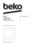
Figure 2 - Turbo Superterm Components
Expansion Boards and Accessories
Memory Expansion
•
•
Standard Memory: The standard UL version uses a
static 512K x 8 RAM (U61) to support downloadable
code, to provide working RAM, and to support the card
database.
2-4 MB Expansion: Two optional 2MB of RAM memory expansion boards (2X2MB) may be added to the
Turbo Superterm, providing support for a maximum
210,000 card holders.
NOTE: The Standard RAM (512K x 8)
should ONLY be removed when BOTH
2X2MB expansion boards are installed. See
memory upgrade information beginning on
page 82.
Digital Input/Digital Output (DI/DO) Board
The DI/DO Board supports up to eight, non-supervised inputs
and provides 16 relay outputs to devices controlled by twostate signals (see Figure 2).
Supervised Alarm Board
The Supervised Alarm Board supports 16 supervised alarms,
with each alarm having five states (normal, abnormal, open,
short, and ground fault).
Battery Backup
During power interruptions, the Turbo Superterm continues
operating for a maximum of 4 hours via an on-board 7 AmpHour back-up battery (standard version) or a 12 AmpHour
back-up battery (expanded version).
The backup battery provides DC power for all Turbo Superterm access control and alarm monitoring functions. After
charging for 48-hours, the battery carries the rated load for
four or more hours. A low-voltage battery sensing circuit protects the Turbo Superterm by disconnecting the battery from
the main circuit if the battery discharges too much current.
To provide adequate power for a minimum of four hours, the
standard Turbo Superterm 7 AmpHour battery allows the installation of only one DI/DO board.
The expanded Turbo Superterm version includes a 12AH
backup battery to provide adequate power for two DI/DO
boards for a minimum of four hours.
Power Transformer
The step-down transformer provides 14VAC to the on-board
linear power supply. An AC power terminal block and
grounding screw provide connection points for the three incoming 120VAC service lines.
Optional Turbo Superterm versions are available that will support 220VAC power where required for use outside of the
United States.
11
Turbo Superterm P1800 v1.2
INSTALLATION
INSTALLATION
CAUTION
Prevent the risk of a fire by replacing ALL
fuses with the same type and rating (see
page 88, Backup Battery Inline Fuse Replacement). The main fuse protects the linear power supply circuit against excessive
currents and short circuits. Failure of the
linear power supply (other than a blown
fuse) fuse usually indicates a fault in a
power supply component. There are no
user-servicable parts in the Turbo Superterm cabinet. The power supply must be
replaced if it fails.
WARNING
The linear power supply has exposed terminals (see page 11). DO NOT probe the
Turbo Superterm cabinet and expose yourself to high voltage and a shock hazard.
WARNING
The risk of a serious electrical shock exists
if the wiring harness power connector is
removed from the Turbo Superterm circuit
board, but AC power remains live at the
AC Input Terminal Block (see Figure, page
11).
WARNING
Prevent shock during servicing when the
POWER ON lamp is disconnected. To determine if power is present, check the status
of the Turbo Superterm's top LED (see
page 80, LED Diagnostics). The top LED
will be illuminated if power is present.
Only qualified service personnel familiar with all local building codes should attempt this installation. Take appropriate
safeguards to avoid unintentional operation by employees and
maintenance personnel working about the premises.
The installation of each Turbo Superterm system should be
completed and tested on its own before connecting into a network. Any possible wiring or installation problems are magnified many times by the complexity of the network.
Once an individual panel has been tested and found operating
satisfactorily, it can then be safely brought into the network.
The following warnings are designed for the safety of the
Turbo Superterm install/service technician and for the continued proper function of the Turbo Superterm unit.
About This Manual
This manual describes the installation of the Turbo Superterm
Access Control Unit and the specific accessories that connect
to it.
NOTES:
Notes are included with a procedure informing the technician about related material.
CAUTION
Cautions indicate that a particular process
requires special attention.
WARNING
Warnings indicate that a particular process
exposes the technician to live circuits or
that making wrong connections can lead to
equipment failure.
CAUTION
Do not place accessory circuit cables in the
same conduit sections containing power
cables.
Turbo Superterm P1800 v1.2
12
INSTALLATION
21.5 inches high (546mm)
X
21.25 inches wide (540mm)
X
7.0 inches deep (178mm)
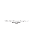
Installation Preparation
First, select a mounting location within a secure, limited access
area (see Figure 3). Ensure that an "earth ground" connection
is available near the Turbo Superterm installation site. Note
the type of wall construction that the enclosure will be secured
to.
•
•
Determine that adequate space is available for mounting
the Turbo Superterm cabinet on a wall with no interference from wires, pipes, or other obstructions.
•
Confirm that adequate free space exists on both sides of
the Turbo Superterm cabinet for cabling conduit entering
and exiting the cabinet.
•
Determine the directions of the cabling conduit exiting the
Turbo Superterm cabinet. Confirm sufficient access to
ceilings and/or walls before fitting the conduit lengths.
Proper installation of the Turbo Superterm cabinet requires an area of free space measuring:
Turbo
Superterm
Panel
Assembly
Figure 3 - Turbo Superterm Installation Location
13
Turbo Superterm P1800 v1.2
INSTALLATION
Cabinet Mounting
Inspect the mounting surface around the proposed installation
site. The mounting surface must be capable of supporting 55
pounds (25Kg) plus any additional weight of the installation
hardware.
CAUTION
Use only suitable mounting hardware for the
type of wall construction encountered.
3.
Place the Turbo Superterm cabinet out of the way.
4.
Drill pilot holes to the required depth and size for the
mounting screws.
5.
Insert the mounting screws into the wall. Leave approximately one quarter of the screw's length protruding from
the wall.
NOTE: Do not tighten screws completely at this time.
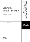
1.
Determine the Turbo Superterm cabinet mounting location.
6.
2.
Mark the four mounting holes against the mounting surface using the Turbo Superterm cabinet as a template or
using the measurements provided in Figure 4.
Secure the Turbo Superterm cabinet to the mounting surface
and tighten the remaining length of the screws.
Place the Turbo Superterm cabinet over the mounting
screws.
NOTE: Mark the small oval portion of the cabinet screw
holes (see Figure 5, Detail A).
Figure 4 - Turbo Superterm Cabinet Mounting Hole
Dimensions
Figure 5 - Turbo Superterm Mounting Screws
Turbo Superterm P1800 v1.2
14
INSTALLATION
standard two-size knockouts located on the left and right sides
of the cabinet (see Figure 6). The outer knockout size accepts
EIA standard 1-inch conduit connectors and the inner knockout accepts EIA standard 3/4-inch conduit connectors.
Cable Routing
All associated cabling for the Turbo Superterm is divided into
two categories:
•
•
Power Cables and Accessory Relay Devices
This category contains all the power cables servicing the
Turbo Superterm and any accessory relay controlled devices connected to it.
Grounding Accessory Drain and Shield Wires
Ensure electromagnetic compatibility and reliable performance
by keeping all accessory drain and shield wires as short as possible.
Communication Cables
This category contains all the communication cabling between the Turbo Superterm and all communication devices, all alarm devices, and all card reader devices.
All accessory drain and shield wires (except RS-232) connect
to ground posts mounted along the knockout strips on both
sides of the Turbo Superterm cabinet (see Figure 6).
The following procedures assure proper installation of all drain
and shield wires.
NOTE: For proper operation of the Turbo Superterm, route EACH category of cabling in SEPARATE conduit (i.e., DO NOT mix alarm and communication cables in the same conduit as relay
and power cables).
•
•
Incoming Power Conduit Knockout
The Turbo Superterm System requires 120VAC, 60 Hz voltage
to the AC Input Power Terminal Block (see page 16). The
power cabling is delivered to the Turbo Superterm through a
knockout located on the lower center of the left side cabinet
wall (see Figure 6). The knockout accepts EIA standard 1inch or 3/4 inch conduit connectors.
•
•
Carefully remove the cable jacket after the cable enters the
Turbo Superterm cabinet.
Place the drain and shield wires under the ground post
screw.
Verify a good connection and tighten the ground post
screw.
Connect the accessory wires to the appropriate terminal
strip on the Turbo Superterm circuit board.
NOTE: All wiring must conform to National Electric Code (NEC), NFPA 70, as well as any local
building codes.
Accessory Conduit Knockouts
All cabling for the Turbo Superterm is routed through EIA
Turbo Superterm Accessory
Knockouts (18 total)
Turbo
Superterm
Cabinet
Turbo Superterm Accessory
Knockouts (11 total)
Figure 6 - Cabling Conduit Knockouts
15
Turbo Superterm P1800 v1.2
POWER CONNECTIONS
120VAC Power (220 VAC Optional)
POWER CONNECTIONS
The Turbo Superterm system requires 120VAC, 60 Hz voltage. The incoming 120VAC source voltage connects to the
AC Input Power Terminal Block located in the lower left-hand
corner of the Turbo Superterm cabinet (see Figure 7).
AC Power Source Grounding
The Turbo Superterm main circuit board has built-in surge
suppression devices. The surge suppressors require a good
earth ground connection to operate effectively.
NOTE: Use of a dedicated, unswitched 120VAC
power source results in optimal performance with
minimum interference. Turbo Superterm units with
optional 220VAC power are available where required for use outside of the United States.
Check the DC resistance between the 120VAC power ground
terminal and a known earth ground such as a metal water pipe
or structural steel building component
CAUTION
DC resistance between the 120VAC power ground
terminal and a known earth ground must be no
greater than 50 ohms.
WARNING
Verify that the AC source voltage is switched off
at the breaker panel before proceeding with connections.
If the DC resistance is acceptable, install the 120VAC power
cabling using the ground terminal as the earth ground.
Table 1 lists the incoming 120VAC source voltage connections
to the AC Input Power Terminal Block.
Table 1- AC Input Power Terminal Block Connections
Incoming 120VAC
Wire Color
AC Input Terminal
Block
Line
Black
L
Neutral
White
N
Ground
Green
Turbo Superterm Cabinet
Figure 7 - AC Input Power Terminal Block
Turbo Superterm P1800 v1.2
16
POWER CONNECTIONS
Turbo Superterm Circuit Board Layout
The Turbo Superterm circuit board (see Figure 8) provides
wiring terminal strips for external access control devices (card
readers, keypads, alarms, etc.).
The following descriptions in this manual reference the Turbo
Superterm main circuit board, shown below, and use cutaway
drawings to identify specific locations on the circuit board.
Figure 8 - Turbo Superterm Circuit Board Layout
17
Turbo Superterm P1800 v1.2
POWER CONNECTIONS
Table 2 - Connection Table for Step-Down Transformer
Power Input Terminal Strip
Step-Down Transformer Connection
The Turbo Superterm circuit board is powered from an internal power supply driven by a separate step-down transformer.
The step-down transformer is mounted on the bottom ledge of
the Turbo Superterm cabinet (see Figure 2, page 11, Turbo
Superterm Components).
Pin #
Function
1
REG IN
2
DC
3
CHARGER
The Step-Down transformer connects to the Turbo Superterm
circuit board through the Power Input terminal strip (see Figure 8, page 17, Turbo Superterm Circuit Board Layout).
4
+12V
5
-BAT
Table 2 lists the connections between the Step-Down Transformer and the Turbo Superterm Power Input terminal strip.
Refer to Figure 9, page 19, while reading Table 2 for StepDown Transformer to Turbo Superterm Circuit Board connections.
6
+BAT
7
NOTES: If the Turbo Superterm is NOT using the optional Expansion Power Supply, leave the female Molex
connector from the transformer unconnected.
If the Turbo Superterm is equipped with an Expansion
Power Supply, connect the female Molex connector from
the Expansion Power Supply to the male Molex connector
of the Transformer Assembly (see Figure 9).
Wire Color
Function
AC2
Black
AC Power
8
GND
Yellow
GND
9
AC1
White
AC Power
Table 3 - Connection Table for Terminal Strip
Power Input Terminal Strip
Power Input Terminal Strip Jumpers
Backup Battery
Pin #
Function
Jumper
1
REG IN
Jump to Pin 2 (DC)
2
DC
Jump to Pin 1 (REG
IN) &3 (CHARGER)
Pins 1, 2, and 3 of the standard Turbo Superterm (with no Expansion Power Supply) must be jumped together. Table 3
lists the pin connections on the Power Input terminal strip that
require jumpers. Refer to Figure 9, page 19 while reading
Table 3 for Power Input terminal strip jumper connection.
NOTE: If using an Expansion Power Supply, pin 1 must
be open, and pins 2 and 3 must be jumpered together. Refer to CAUTION on page 19.
Battery Backup Connection
During power interruptions, the Turbo Superterm continues
operating for a maximum of 4 hours via an on-board 7A-hour
back-up battery (standard version) or a 12A-hour back-up battery (expanded version).
3
CHARGER
4
+12V
5
-BAT
6
+BAT
7
AC2
8
GND
9
AC1
Jump to Pin 2 (DC)
Table 4 - Connection Table for Backup Battery
Power Input Terminal Strip
Table 4 lists the connections from the Battery Backup to the
Turbo Superterm Power Input terminal strip. Refer to Figure
9, page 19, while reading Table 3 for Battery Backup to
Turbo Superterm Circuit Board connections.
WARNING
Do NOT connect the Backup Battery or provide
AC source voltage to the Turbo Superterm until
all accessory cabling is completed.
Turbo Superterm P1800 v1.2
Transformer Assembly
18
Pin #
Function
1
REG IN
2
DC
3
CHARGER
4
+12V
5
-BAT
6
+BAT
7
AC2
8
GND
9
AC1
Backup Battery
Function
Neg (-) post
Pos (+) post
POWER CONNECTIONS
Table 5 - Connection Table for Expansion Power Supply
Expansion Power Supply Connection
Power Input Terminal Strip
The Turbo Superterm circuit board provides +12V power for
accessories via an expansion power supply.
Expansion Power Supply
Pin #
Function
Table 5 lists the connections from the Expansion Power Supply to the Power Input terminal strip (see Figure 9).
1
REG IN
2
DC
Jumper to pin 3 (CHARGER)
NOTE: Connect the female Molex connector from the
Expansion Power Supply to the male Molex connector of
the Transformer Assembly (see Figure 9).
3
CHARGER
Jumper to pin 2 (DC)
4
+12V
Red
Pos (+) post
5
-BAT
Black
Neg (-) post
6
+BAT
7
AC2
8
GND
9
AC1
CAUTION
Using the Expansion Power Supply requires placing a jumper between pins 2 and 3 of the Power
Input terminal strip (see Figure 9 and Table 5).
NOTE: Pin 1 must remain OPEN.
Wire Color
Function
Turbo Superterm Circuit Board
Figure 9 - Connecting Transformer, Battery, and Power Supply to Turbo Superterm Circuit Board
19
Turbo Superterm P1800 v1.2
DOOR CONNECTIONS
DOOR CONNECTIONS
Inputs from Card Readers, Keypads, and Door Alarms connect
to the Turbo Superterm via eight terminal strips (labeled DR1,
DR2, DR3, DR4, DR5, DR6, DR7, and DR8).
Wiegand/Proximity Reader Cable Requirements
Wiegand/Proximity Readers require a 5-conductor cable between the Turbo Superterm and the particular unit (see Figure
10).
NOTE: The terminal strips are grouped in pairs on one connector block.
• Terminal strips DR1 and DR2 are paired together on the
same connector block located in the upper left-hand comer
of the Turbo Superterm Circuit Board (see page 17, Turbo
Superterm Circuit Board Layout).
• Terminal strips DR3 and DR4 are paired together on the
same connector block located on the lower left-hand
comer of the Turbo Superterm Circuit Board.
• Terminal strips DR5 and DR6 are paired together on the
same connector block in the upper right-hand corner of the
Turbo Superterm Circuit Board.
• Terminal strips DR7 and DR8 are paired together on the
same connector block located on the lower right-hand side
of the Turbo Superterm Circuit Board.
NOTE: DO NOT use twisted pair cables.
Readers may have a combined maximum current draw of
500mA (+12VDC) or 800mA (+5VDC) per Turbo Superterm
Circuit Board.
EXAMPLE: If eight identical +5VDC Readers are connected
to one Turbo Superterm, each Reader could draw a maximum
of 100mA.
Table 7 lists the cable gauge-vs-length requirements for proper
operation of the Turbo Superterm and a Wiegand/Proximity
Reader.
Table 7 - Cable Requirements for Wiegard/Proximity
Readers
Unit
Distance
Wire Gauge
(maximum)
Wiegand Reader
500ft/153m
22AWG Shielded w/
drain
Wiegand/Proximity Reader Connections
Wiegand/Proximity Readers connect to terminal strips DR1
through DR8 (see Figure 10). Terminal strips DR1 through
DR8 follow the same connection procedures.
Table 6 lists the connections between the DR1 through DR8
terminal strips and the Wiegand/Proximity Readers.
Table 6 - Connection Table for Wiegand /Proximity
Reader
DRx Terminal
Strip Pin #
Function
Wire Color
1
+5VDC
Red*
3
+12VDC
Red*
4
Ground
Black
5
LED
Brown
6
Data-1/DAT
White
7
Data-0/CLK
Green
Proximity Reader
18AWG Shielded w/
drain
CAUTION
Keep all drain and cable shield wires between the
Turbo Superterm and any Wiegand/Proximity Readers short. Connect drain and cable shield wires to
the ground posts located on both sides of Turbo Superterm
cabinet. DO NOT ground drain wires and cable shields at any
other point.
Note: Please refer to reader manufacturer for specific instructions and specifications.
* Proximity Reader may be powered by either
+5VDC or +12VDC.
Turbo Superterm P1800 v1.2
500ft/153m
20
DOOR CONNECTIONS
Turbo Superterm Cabinet
Ground Post
Turbo Superterm Circuit Board
Figure 10 - Wiegand/Proximity Reader Connection to Turbo Superterm Board
21
Turbo Superterm P1800 v1.2
DOOR CONNECTIONS
Magnetic Stripe Reader Connection
Magnetic Stripe Reader Cable Requirements
Magnetic Stripe Readers connect to terminal strips DR1
through DR8 (see Figure 11). Terminal strips DR1 through
DR8 follow the same connection procedures.
Magnetic Stripe Readers require a 5-conductor cable between
the Turbo Superterm and the particular unit (see Figure 11).
Table 8 lists the connections between the DR1 through DR8
terminal strips and the Magnetic Stripe Reader.
Table 8 - Connection Table for Magnetic Stripe Reader
DRx Terminal Strip Pin #
Function
1
4
5
6
7
NOTE: DO NOT use twisted pair cables.
If the Magnetic Stripe Reader does not feature an LED indicator, substitute with a 4-conductor cable.
Table 9 lists the cable gauge-vs-length requirements for proper
operation of the Turbo Superterm and Magnetic Stripe Readers.
+5VDC
Ground
LED
Data-1/DAT
Data-0/CLK
Table 9 - Cable Requirements for Magnetic Stripe Reader
Unit
Distance
Wire Gauge
Magnetic
(maximum)
22AWG
Stripe
500ft/153m
Shielded w/drain
Reader
CAUTION
Keep all drain and cable shield wires between the Turbo Superterm and Magnetic Stripe Readers short. Connect drain and cable shield wires to the ground posts located on both sides of Turbo Superterm cabinet. DO
NOT ground drain wires and cable shields at any other point.
Note: Please refer to reader manufacturer for specific instructions and specifications.
Turbo Superterm
Cabinet Ground Post
Turbo Superterm Circuit Board
Figure 11 - Magnetic Stripe Reader Connection to Turbo Superterm Board
Turbo Superterm P1800 v1.2
22
DOOR CONNECTIONS
Keypad Connection
Keypad Cable Requirements
Twelve-position Keypads connect to terminal strips DR 1
through DR8 (see Figure 12). Terminal strips DR1 through
DR8 follow the same connection procedures.
Keypads require a 22AWG, 7-conductor, stranded, shielded,
cable with drain wire between the Turbo Superterm and the
particular unit (see Figure 12).
Table 10 lists the connections between the DR 1 through DR8
terminal strips and the Keypad.
NOTE: DO NOT use twisted pair cables.
Table 11 lists the cable gauge-vs-length requirements for
proper operation of the Turbo Superterm and the Keypad.
Table 10 - Connection Table for Keypad Reader
DRx Terminal
Strip
Pin #
Function
Wire Color
8
Row 1
Brown
9
Row 2
Red
10
Row 3
Orange
11
Row 4
Yellow
12
Column 1
Green
13
Column 2
Blue
14
Column 3
Violet
Table 11- Cable Requirements for Keypads
Unit
Keypad
Distance
(maximum)
500ft/153m
Wire Gauge
22AWG Shielded w/
drain
CAUTION
Keep all drain and cable shield wires between the Turbo Superterm and Keypads short. Connect drain and cable shield wires to the ground posts located on both sides of Turbo Superterm cabinet. DO NOT ground drain
wires and cable shields at any other point.
Turbo
Superterm
Cabinet
Ground Post
Turbo Superterm Circuit Board
Figure 12 - Keypad Connection to Turbo Superterm Board
23
Turbo Superterm P1800 v1.2
DOOR CONNECTIONS
Door Status Sensor Connection
Door Status Sensor Cable Requirements
Door Status sensors connect to the Turbo Superterm through
eight terminal strips labeled DR 1 through DR8 (see Figure
13).
Door Status sensors require a 22AWG, 2-conductor, stranded,
shielded, cable with drain wire between the Turbo Superterm
and the particular unit (see Figure 13).
Table 12 lists the connections between the DR1 through DR8
terminal strips and the Door Status sensor.
NOTE: DO NOT use twisted pair cables.
Table 12 - Connection Table for Door Status Sensor
DRx Terminal
Strip
Signal
Pin #
Door Status
Table 13 lists the cable gauge-vs-length requirements for
proper operation of the Turbo Superterm and the Door Status
sensor.
Table 13 - Cable Requirements for Door Status Sensor
Unit
Distance
Wire Gauge
Door
500ft/153m
22AWG Shielded w/
Status Sensor
drain
Sensor Function
15
Alarm
Positive
16
Return
Negative
NOTES: Refer to page 38, Alarm Connection, to configure
Door Status sensors as supervised alarms.
Door Status sensor connections to the Turbo Superterm are not
sensitive to polarity.
CAUTION
Keep all drain and cable shield wires between the Turbo Superterm and Keypads short. Connect drain and cable shield wires to the ground posts located on both sides of Turbo Superterm cabinet. DO NOT ground drain
wires and cable shields at any other point.
Turbo Superterm Cabinet
Ground Post
Turbo Superterm Circuit Board
Figure 13 - Door Status Sensor to Turbo Superterm Connections
Turbo Superterm P1800 v1.2
24
DOOR CONNECTIONS
Request-to-Exit (Bypass) Sensor Connection
Request-to-Exit Sensor Cable Requirements
Request-to-Exit sensors (also known as Bypass sensors) work
in conjunction with Door Status Sensors to provide complete
facility entry and exit control. The Request-to-Exit sensor input connects to the same Turbo Superterm terminal strip (DR1
through DR8) that the associated Door Status Sensor connects
to (see Figure 14).
Request-to-Exit sensors require a 22AWG, 2-conductor,
stranded, shielded, cable with drain wire between the Turbo
Superterm and the particular unit (see Figure 14).
Table 14 lists the connections between the DR1 through DR8
terminal strips and the associated Request-to-Exit sensor.
Table 15 lists the cable gauge-vs-length requirements for
proper operation of the Turbo Superterm and the Request-toExit sensor.
NOTE: DO NOT use twisted pair cables.
Table 14 - Connection Table for Request-to-Exit Sensor
DRx Terminal
Strip Pin #
Signal
Request-to-Exit
Sensor Function
17
Alarm
Positive
18
Return
Negative
Table 15 - Cable Requirements for Request-to-Exit Sensor
Unit
Distance
Wire Gauge
Request-to-Exit
(maximum)
22AWG Shielded w/
Sensor
500ft/153m
drain
NOTE: Request-to-Exit sensor connections to the Turbo Superterm are not sensitive to polarity.
CAUTION
Keep all drain and cable shield wires between the Turbo Superterm and Keypads short. Connect drain and cable shield wires to the ground posts located on both sides of Turbo Superterm cabinet. DO NOT ground drain
wires and cable shields at any other point.
Turbo Superterm Cabinet
Ground Post
Turbo Superterm Circuit Board
Figure 14 - Request-to-Exit Sensor to Turbo Superterm Connection
25
Turbo Superterm P1800 v1.2
RELAY CONNECTIONS
RELAY CONNECTIONS
Description
The Turbo Superterm provides 17 Form C relays to control
door strikes, door alarm shunts, alarms, cameras, etc.
The relays are divided into three categories:
•
•
•
Door Strike Relays
Auxiliary Relays
Console Relay
Door Strike Relays
Eight relays are designated as door strike relays and work in
conjunction with card readers and keypads to control access at
particular door sites.
Console Relay
The Console Relay may be linked to specific events such as
invalid door access, alarm input, and tamper switch input. The
console relay is linked to an event through software.
The console relay is labeled RLY 17 and is located on the far
right hand side of the first bank of relay terminal strips of the
Turbo Superterm Circuit Board (see Figure 15).
Relay Characteristics
The relays on the Turbo Superterm Circuit Board all share the
following characteristics:
Form C relay with a contact rating of 2A at 28VDC.
The Normally Open (NO) and the Normally Closed (NC) contacts are the default state of non-energized relays.
Metal oxide varistors (MOVs) are placed across the contacts to
reduce electrical noise. The MOVs limit any noise caused by
the strike coil to 56 volts.
The door strike relays are the first bank of relay terminal strips
labeled, from left to right, RLY 1, RLY 3, RLY 5, RLY 7,
RLY 9, RLY 11, RLY 13, and RLY 15, located on the bottom
of the Turbo Superterm Circuit Board (see Figure 15).
NOTES: Installing a 56 volt MOV at the strike coil
further reduces possible noise input.
Because of this noise, door strike wiring MUST NOT
be put in the same conduit with other wiring.
Auxiliary Relays
Eight relays are designated as auxiliary relays and may be used
for access control functions such as door alarm shunts.
The auxiliary relays are the second bank of relay terminal
strips labeled, from left to right, RLY 2, RLY 4, RLY 6, RLY
8, RLY 10, RLY 12, RLY 14, and RLY 16, located on the
Turbo Superterm Circuit Board (see Figure 15).
Turbo Superterm P1800 v1.2
Using door strikes with a coil voltage greater than 28VDC
or 28VAC requires using external relays that can be
driven by Turbo Superterm relays.
Additional MOV's are available form Continental Instruments
as part number (RV0005).
26
RELAY CONNECTIONS
Turbo Superterm Circuit Board
Figure 15 - Turbo Superterm Circuit Board Relay Location
27
Turbo Superterm P1800 v1.2
RELAY CONNECTIONS
The default settings of the jumpers, as shipped from the
factory, are the REMOTE power mode. Refer to page 78
(Table 50) for specific information about setting the door
strike jumpers.
Door Strike Relay Operation
The Turbo Superterm offers two configurations for controlling
power to each door strike circuit:
Relay circuits in the REMOTE configuration are isolated
from one another and isolated from the Turbo Superterm
power supply.
The LOCAL strike power configuration simplifies wiring at
the site by using a single power source to operate several door
control circuits (see Figure 16). This option is selected by setting a pair of jumpers on the Turbo Superterm printed circuit
board.
The REMOTE strike power configuration provides conventional dry-contact outputs, typically controlling a circuit where
the power source for the electric lock is near the door controlled by the relay (see Figure 16).
NOTES: Both LOCAL and REMOTE strike power configurations may be mixed on the same Turbo Superterm panel.
Operating door strike relays in either the LOCAL or the
REMOTE mode requires setting two jumpers per relay.
Turbo Superterm P1800 v1.2
28
RELAY CONNECTIONS
Turbo
Superterm Circuit Board
28VDC or 28VAC max.
Figure 16 - LOCAL and REMOTE Power Configurations
29
Turbo Superterm P1800 v1.2
RELAY CONNECTIONS
LOCAL Power Connection
In LOCAL power mode, a single, external power supply
(28VDC or 28VAC max.) is mounted outside of and adjacent
to the Turbo Superterm cabinet. This supply provides power
to a maximum of eight Turbo Superterm door strike relays
through the STKPWR terminal strip located on the lower edge
of the Turbo Superterm circuit board (see Figure 17).
Strike power is routed through the Turbo Superterm circuit
board to the individual relay connectors, thus eliminating the
need for separate power supplies at each door.
•
•
The STK- input (STKPWR - Pin 4) is routed to the COMMON (C) relay connection (RLY #X - Pin 2).
The STK+ input (STKPWR - Pin 3) is routed through the
DIS pins (1 and 2) to the Normally Open (NO, RLY #X Pin 1) or the Normally Closed (NC, RLY #X - Pin 3), depending on the state of the relay.
Emergency Sensor Connection
An external emergency sensor may be used to disconnect the
LOCAL strike power supply if an emergency condition is detected.
The emergency sensor is placed in series with the STK+ signal
by connecting it between Pin 1 and Pin 2 of the STKPWR terminal strip (see Figure 18).
NOTES: The emergency sensor must be a Normally Closed (NC) switch and the strike relays
must be wired in a Normally Closed (NC) configuration (refer to page 32, LOCAL Power Door Strike
Connection).
If an emergency sensor is not used, place a jumper between
Pin 1 and Pin 2 on the STKPWR terminal strip (see Figure 17).
A Normally Closed (NC) emergency switch may be used in
conjunction with the Local power mode to disconnect the
strike power upon an emergency situation.
Table 17 - Connection Table for Emergency Sensor and
External Power Supply
NOTE: Operating a door strike relay in the LOCAL mode
requires setting two jumpers per relay. Refer to page 78
(Table 50) for specific information about setting the door
strike jumpers.
All door strike relays connected in the LOCAL power configuration operate from the same power source and must have the
same voltage rating.
If an emergency sensor is not used, install a jumper between
Pin 1 (DIS) and Pin 2 (DIS) on the STKPWR terminal strip.
Table 16 lists the connections between the STKPWR terminal
strip and the external power supply (see Figure 17).
Table 16 - Connection Table for External Power Supply
STKPWR Terminal Strip
Positive (+)
Pin # 3
Negative (-)
Pin #4
Turbo Superterm P1800 v1.2
STKPWR Terminal Strip
Emergency Sensor
Pin #1 (DIS)
Emergency Sensor
Pin #2 (DIS)
Power Supply Positive (+)
Pin #3 (STY, +)
Power Supply Negative (-)
Pin #4 (STK -)
NOTE: Normally Closed (NC) emergency sensor connections are not sensitive to polarity.
All strike relay circuits (odd numbered relays) are individually
fuse protected in both the LOCAL or the REMOTE configuration.
Power Supply
Device
30
RELAY CONNECTIONS
Turbo Superterm Circuit Board
Figure 17 - LOCAL Power Supply Connection
Turbo Superterm Circuit Board
Figure 18 - Emergency Sensor Connection
31
Turbo Superterm P1800 v1.2
RELAY CONNECTIONS
LOCAL Power Door Strike Connection
All door strike relays operating in LOCAL power mode distribute strike power from the LOCAL power supply. However, each relay may be configured in one of two specific
ways.
Door Strike Relay Connection - Normally
Closed
Table 19 lists the connections between the RLY#x terminal
strip and the associated door strike for a Normally Closed
(NC) condition (see Figure 20).
1. A door strike relay set in a Normally Closed (NC) configuration holds a door strike circuit closed until an event triggers the relay and releases the door strike.
Table 19 - Connection Table for Door Strike Relay Normally Closed (NC) Condition
2. A door strike relay set in a Normally Open (NO) configuration keeps a door strike circuit open until an event triggers
the relay and engages the door strike.
NOTE: Operating the door strike relays with an
emergency sensor requires Normally Closed (NC)
conditions (power is disconnected from the door
strike in emergency situations).
Door Strike Relay Connection - Normally
Open
Table 18 - Connection Table for Door Strike Relay Normally Open (NO) Condition
RLY#x Pin
Positive (+)
Pin 1
Common (-)
Pin 2
NOTE: Operating door strike relays on LOCAL power requires setting two jumpers per relay. Refer to page 78 (Table
50), Door Strike Jumper Settings, for specific information
about setting the jumpers.
Turbo Superterm P1800 v1.2
RLY#x Pin
Positive (+)
Pin 3
Common (-)
Pin 2
NOTE: Operating door strike relays on LOCAL power requires setting two jumpers per relay. Refer to page 78 (Table
50), Door Strike Jumper Settings, for specific information
about setting the jumpers.
Table 18 lists the connections between the RLY#x terminal
strip and the associated door strike for a Normally Open (NO)
condition (see Figure 19).
Door Strike Signal
Door Strike Signal
32
RELAY CONNECTIONS
Turbo Superterm Circuit Board
Figure 19 - LOCAL Power Door Strike Relay Connection - Normally Open (NO) Condition
Turbo Superterm Circuit Board
Figure 20 - LOCAL Power Door Strike Relay Connection - Normally Closed (NC) Condition
33
Turbo Superterm P1800 v1.2
RELAY CONNECTIONS
REMOTE Power Mode
In REMOTE power mode, each door strike operates from an
individual power supply (typically a transformer mounted at
the door site). In the REMOTE power mode, the door strike
relays operate as conventional dry contacts and may be configured as Normally Open (NO) or Normally Closed (NC).
NOTES: Door strike relays operating in the REMOTE mode
do not respond to an emergency sensor.
Operating a door strike relay in the REMOTE mode requires
setting two jumpers per relay. Refer to page 78 for specific
information about setting the door strike jumpers.
Door Strike Relay Connection - Normally
Open
Table 20 lists the connections between the RLY#x terminal
strip and the door strike for a Normally Open (NO) relay condition (see Figure 21).
Table 20 - Connection Table for Door Strike Relay Normally Open (NO) Condition
Door Strike Signal
RLY#x
Positive (+)
Pin 1
Common (-)
Pin 2
Strike Jumper Settings, for specific information about setting
the jumpers.
Auxiliary Relay Connection
The Turbo Superterm supports eight auxiliary relays for controlling external devices including, door alarm shunts, cameras, temperature controls, intercoms, area lighting, or any
other device using electrical inputs to change the status of a
control circuit.
Auxiliary devices only connect to even numbered Turbo Superterm relays. The eight relays are located on the bottom center of the Turbo Superterm circuit board above the door strike
relays.
The eight auxiliary relays are labeled: RLY 2; RLY 4; RLY 6;
RLY 8; RLY 10; RLY 12; RLY 14; RLY 16.
Auxiliary Relay Power Requirements
The Turbo Superterm does not provide on-board power to the
eight auxiliary relays. Each auxiliary relay may be used to
switch an external signal.
Auxiliary Relay Connection - Normally Open
(NO)
Table 22 lists the connections for an Auxiliary relay in a normally open configuration.
Table 22 - Connection Table for Auxiliary Relay Normally Open (NO) Condition
NOTE: Operating door strike relays on REMOTE power requires setting two jumpers per relay. Refer to page 78, Door
Strike Jumper Settings, for specific information about setting
the jumpers.
Door Strike Relay Connection - Normally
Closed
Table 21 lists the connections between the RLY#x terminal
strip and the door strike for a Normally Closed (NC) relay condition (see Figure 22).
RLY#x
Positive (+)
Pin 3
Common (-)
Pin 2
Normally Open
Pin 1
Common
Pin 2
Table 23 lists the connections for an Auxiliary relay in a normally closed configuration.
Table 23 - Connection Table for Auxiliary Relay Normally Closed (NC) Condition
NOTE: Operating door strike relays on REMOTE power requires setting two jumpers per relay. Refer to page 78, Door
Turbo Superterm P1800 v1.2
RLY#x
Aux Relay Connection - Normally Closed (NC)
Table 21 - Connection Table for Door Strike
Relay - Normally Closed (NC) Condition
Door Strike Signal
Signal
34
Signal
RLY#x
Normally Closed
Pin 3
Common
Pin 2
RELAY CONNECTIONS
NOTE: Strike power is PROVIDED when
the relay activates.
Turbo Superterm Circuit Board
Figure 21 - REMOTE Power Fail Secure Door Strike Relay Connection - Normally Open (NO) Condition
NOTE: Strike power is REMOVED when the
relay activates.
Turbo Superterm Circuit Board
Figure 22 - REMOTE Power Magnetic Lock or Fail Safe Door Strike Relay Connection - Normally Closed (NC) Condition
35
Turbo Superterm P1800 v1.2
AUXILIARY POWER
AUXILIARY POWER
WARNING
Verify that the main power to the Turbo Superterm circuit board is OFF before connecting any
optional devices.
The AUX POWER terminal strip (labeled 12_V) provides
+12VDC power outlets for a maximum of three expansion I/O
option boards or auxiliary devices. The AUX POWER terminal strip is located in the lower right-hand corner of the Turbo
Superterm circuit board (see Figure 23). For specific information regarding expansion boards, refer to page 56, Expansion
Input/Output Boards.
WARNING
Observe Positive and Negative wire polarity between option boards and the Turbo Superterm.
Table 24 lists the AUX POWER terminal strip pin numbers
and their associated functions.
Additional +12VDC Power Outlets
Table 24 - AUX POWER (12_V) Terminal Strip
Functions
Pin
Function
1
+12
2
GND
3
+12
4
GND
5
+12
6
GND
An additional eight + 12VDC outlets are available (if not being
used for readers) for powering accessories including motion
detectors and +12V alarm devices.
The third pin (Pin 3) of the DR1 through DR8 terminal strips
provides +12VDC to suitable access control accessories (see
Figure 24).
NOTE: +12VDC current draw is limited to a total maximum
value of 0.50 Amps for the basic Turbo Superterm version
(without Expansion Power Supply) and 1.60 Amps for the Expanded Turbo Superterm Version (with Expansion Power Supply).
Turbo Superterm P1800 v1.2
36
AUXILIARY POWER CONNECTION
Turbo
Superterm Circuit Board
Figure 23 - Onboard +12VDC Power Supply Outlets
Turbo Superterm Circuit Board
Figure 24 - Additional +12VDC Power Supply Outlets
37
Turbo Superterm P1800 v1.2
ALARM CONNECTION
ALARM CONNECTION
Table 25 - ALARM Terminal Strip Input Pins
Pin
Signal
1
AL 17
2
RT17
3
AL18
4
RT18
5
AL 19
6
RT19
7
AL20
8
RT20
9
AL21
10
RT21
11
AL22
12
RT22
13
AL23
14
RT23
15
AL24
16
RT24
The Turbo Superterm has a total of 24 supervised alarm inputs.
Sixteen alarm inputs are located on the DR1 through DR8 terminal strips, and are used for Request-to-Exit and Door Status
sensor functions (see pages 24 and 25).
An additional eight auxiliary alarm inputs are located on the
ALARM terminal strip located on the upper left-hand comer of
the Turbo Superterm circuit board (see Figures 25 and 26).
These auxiliary alarm inputs may be used for dry contact type
inputs (unsupervised) or supervised alarms.
Supervised Alarms
Supervised alarms provide monitoring of alarm inputs for fault
or tamper conditions. Three additional alarm states may be
detected by installing two-1K Ohm) resistors near the alarm
contacts.
In addition to the standard Normal and Abnormal alarm conditions, the supervised alarms report Open, Closed, and Fault
conditions.
• An Open condition is the result of a cut wire.
Alarm Cable Requirements
•
A Closed condition is the result of shorting the alarm contacts together.
Connecting alarm sensors to the Turbo Superterm board requires 22 AWG, stranded, shielded, cables with drain wires.
•
A Fault condition is the result of grounding one of the
alarm wires.
NOTE: DO NOT use twisted pair wires.
Configuring an Alarm in the Supervised Condition
1) Use two 1K Ohm, 1/4W, ±5% carbon film resistors per
alarm.
2) Install R 1 in parallel with the alarm contacts (see Figure
26).
3) Install R2 in series with the alarm input conductor.
NOTE: For maximum protection, install the resistors close to
the alarm contacts and embed them in epoxy.
Table 25 lists the ALARM terminal strip pin numbers and the
respective signals.
Turbo Superterm P1800 v1.2
CAUTION
Keep all drain and cable shield wires between the
Turbo Superterm and Keypads short. Connect
drain and cable shield wires to the ground posts
located on both sides of Turbo Superterm cabinet. DO
NOT ground drain wires and cable shields at any other
point.
Tamper Switch
The Turbo Superterm cabinet has a built-in tamper switch.
The tamper switch is factory wired and requires no adjustment.
NOTE: When the Tamper Switch closes, all LEDs will extinguish (except AC on LBD1). Refer to page 80, LED Diagnostics, for more specific information.
38
ALARM CONNECTION
Turbo Superterm Cabinet Ground
Post
Turbo Superterm Circuit Board
Figure 25 - ALARM Terminal Strip - Unsupervised Alarm Condition
Turbo Superterm Cabinet
Ground Post
Turbo Superterm Circuit Board
Figure 26 - ALARM Terminal Strip - Supervised Alarm Condition
39
Turbo Superterm P1800 v1.2
COMMUNICATION CONNECTIONS
COMMUNICATION CONNECTION
RS-232 Communications - Host Computer/
Modem
Operating as a stand-alone system, the Turbo Superterm communicates with a host computer (directly or through a modem)
through the RS-232 channel.
Proper RS-232 communications require observing the EIA
standard pin definitions of Data Terminal Equipment (DTE)
and Data Control Equipment (DCE).
NOTE: All RS-232 equipment made by Continental Instruments LLC, including the Turbo Superterm, are configured as
DTE devices.
NOTE: Set switch position 7 of Dip Switch S 1 on the Turbo
Superterm to OFF when using a modem. Refer to page 42, for
specific instructions on setting the S 1 DIP switch.
1) Connect the Transmit pin of the RS-232 device to POLL
terminal strip pin number 4 (labeled RxD) (see Figure 28).
2) Connect the Receive pin of the RS-232 device to POLL
terminal strip pin number 5 (labeled TxD).
3) Connect the Ground pin of the RS-232 device to POLL
terminal strip pin number 6 (labeled GND).
4) Connect the RS-232 cabling drain wire/shield to
GROUND at the host computer/modem end of the cable.
Do Not connect the drain wire at the Turbo Superterm end
of the cable.
Table 27 lists the connections between the POLL terminal strip
and a host computer.
RS-232 Cable Requirements
RS-232 communications between the Turbo Superterm and a
host computer/modem require stranded, 3 conductor, 22 AWG
cable with shielding and a drain wire.
NOTE: DO NOT use twisted pair wires.
Table 27 - Connection Table for Host Computer
Signal
Table 26 lists the cable gauge-vs-length requirements for
proper operation of the Turbo Superterm and the host computer.
Turbo SuHost Com- Host Comperterm
puter DB9-S puter DB25POLL Pin #
pin
S pin
TXD
4
2
3
RXD
5
3
2
GND
6
5
7
Table 26 - RS-232 Cable Gauge-vs-Length
Unit
Distance
Wire Gauge
Host
Computer/
Modem
50ft (15.2m)
(Maximum)
22AWG Shielded
w/Drain
Table 28 lists the connections between the Turbo Superterm
POLL terminal strip and a modem.
Table 28 - Connection Table for Modem
Signal
Turbo Superterm
POLL Pin#
Modem DB25-P
NOTES: A host computer is typically connected to the RS232 cable using either a DB9-S or a DB25-S connector. Modems are typically connected to the RS-232 cable using a
DB25-P connector.
TXD
4
2
RXD
5
3
Address Setting
GND
6
7
Operating the Turbo Superterm on the RS-232 channel requires setting a board address on DIP switch S 1 (address zero
is not valid). Refer to page 42, Network Address Setting, For
specific information.
Turbo Superterm to Host Computer/Modem
Connection
Figure 27 shows a direct Turbo Superterm-to-host computer
connection.
Figure 28 shows a Turbo Superterm-to-host computer connection through a modem.
Turbo Superterm P1800 v1.2
40
COMMUNICATION CONNECTIONS
Turbo Superterm Circuit Board
Figure 27 - Turbo Superterm-to-Host Computer Connection
Turbo Superterm Circuit Board
Figure 28 - Turbo Superterm-to-Modem-to-Computer Connection
41
Turbo Superterm P1800 v1.2
COMMUNICATION CONNECTIONS
Networking
The Turbo Superterm can be networked with a maximum of 62
other Turbo Superterm units or other Continental Instruments access control devices (Superterm, Smarterm, Miniterm, Microterm
and Super Two). NOTE: Multidrop networks are limited to 32
access control devices.
The following network configurations are possible:
RS-232 to RS-422 Networks
RS-232 to RS-422 REPEAT Network
RS-232 to RS-422 MULTIDROP Network
For REPEAT network configurations, cable length between
EACH Turbo Superterm is restricted to a maximum length of
4000 feet (1220m).
For MULTIDROP network configurations, a maximum of 9 panels can be installed with a total cable length of 4000 feet (1220m).
A pair of line drivers is required for every 9 panels--installing a
pair of line drivers after the 9th panel will allow you to expand an
additional 9 panels and 4000 feet (1220m) of cable. Line drivers
can be ordered using part number CICE1940PL-1.
Network Address Settings
RS-422 to RS-422 Networks
RS-422 to RS-422 REPEAT Network
RS-422 to RS-422 MULTIDROP Network
NOTES: If the first Turbo Superterm in the network is less than
50 feet (15.2m) from the host computer, the first Turbo Superterm
in the network may be used to convert the RS-232 polling signal
to RS-422 for the remainder of the network.
If the first Turbo Superterm in the network is more than 50 feet
(15.2m) from the host computer, an RS-422 polling line converter
is required.
Network Jumper Settings
The MODE1 and the EOL2 jumpers on each Turbo Superterm
must be set depending on the type of network configuration.
Refer to page 72 for specific information regarding the EOL2
jumper.
Refer to page 76 for specific information regarding the MODE 1
jumper.
Operating the Turbo Superterm with a host computer, or in a network, requires that each Turbo Superterm ( and other devices)
have an individual, unique address other than zero.
An 8-position DIP switch labeled S 1 mounted on the Turbo Superterm Circuit Board determines each Turbo Superterm's address
(see Figure 29).
Table 29 lists 63 Turbo Superterm address switch positions.
NOTES: Address switch (S I) positions 7 and 8 are not used for
networks connected directly to a host computer. Set
both switches to the ON position.
If the network is connected to the host computer
through a modem, the first Turbo Superterm in the network must have switch position 7 (Modem) set to the
OFF position. All other Turbo Superterm units in the network
must have switch position 7 set to ON.
Addresses shown in Figure 29 are for example purposes only.
Note: Panels on Modems should start with Physical Address #
1 with each new Node to assure proper Panel to Host Dialup.
Network Cable Requirements
Networking multiple Turbo Superterms requires 4-conductor cable (2-two wire twisted pair), stranded, 22AWG, with shielding,
and drain wire.
Turbo Superterm
Circuit Board
Turbo Superterm
Circuit Board
First Network Turbo Superterm
Turbo Superterm
Circuit Board
Second Network Turbo Superterm
Third Network Turbo Superterm
Figure 29 - Turbo Superterm Address Switch (S I) Location
Turbo Superterm P1800 v1.2
42
COMMUNICATION CONNECTIONS
Table 29 - Turbo Superterm Address Switch (S1) Positions
Turbo Superterm Address Switch Position Number
Number
1
2
1
OFF
ON
2
ON
OFF
3
OFF
OFF
4
ON
ON
5
OFF
ON
6
ON
OFF
7
OFF
OFF
8
ON
ON
9
OFF
ON
10
ON
OFF
11
OFF
OFF
12
ON
ON
13
OFF
ON
14
ON
OFF
15
OFF
OFF
16
ON
ON
17
OFF
ON
18
ON
OFF
19
OFF
OFF
20
ON
ON
21
OFF
ON
22
ON
OFF
23
OFF
OFF
24
ON
ON
25
OFF
ON
26
ON
OFF
27
OFF
OFF
28
ON
ON
29
OFF
ON
30
ON
OFF
31
OFF
OFF
32
ON
ON
33
OFF
ON
34
ON
OFF
35
OFF
OFF
36
ON
ON
37
OFF
ON
38
ON
OFF
39
OFF
OFF
40
ON
ON
41
OFF
ON
42
ON
OFF
43
OFF
OFF
44
ON
ON
45
OFF
ON
46
ON
OFF
47
OFF
OFF
48
ON
ON
49
OFF
ON
50
ON
OFF
51
OFF
OFF
52
ON
ON
53
OFF
ON
54
ON
OFF
55
OFF
OFF
56
ON
ON
57
OFF
ON
58
ON
OFF
59
OFF
OFF
60
ON
ON
61
OFF
ON
62
ON
OFF
63
OFF
OFF
3
ON
ON
ON
OFF
OFF
OFF
OFF
ON
ON
ON
ON
OFF
OFF
OFF
OFF
ON
ON
ON
ON
OFF
OFF
OFF
OFF
ON
ON
ON
ON
OFF
OFF
OFF
OFF
ON
ON
ON
ON
OFF
OFF
OFF
OFF
ON
ON
ON
ON
OFF
OFF
OFF
OFF
ON
ON
ON
ON
OFF
OFF
OFF
OFF
ON
ON
ON
ON
OFF
OFF
OFF
OFF
43
4
ON
ON
ON
ON
ON
ON
ON
OFF
OFF
OFF
OFF
OFF
OFF
OFF
OFF
ON
ON
ON
ON
ON
ON
ON
ON
OFF
OFF
OFF
OFF
OFF
OFF
OFF
OFF
ON
ON
ON
ON
ON
ON
ON
ON
OFF
OFF
OFF
OFF
OFF
OFF
OFF
OFF
ON
ON
ON
ON
ON
ON
ON
ON
OFF
OFF
OFF
OFF
OFF
OFF
OFF
OFF
5
ON
ON
ON
ON
ON
ON
ON
ON
ON
ON
ON
ON
ON
ON
ON
OFF
OFF
OFF
OFF
OFF
OFF
OFF
OFF
OFF
OFF
OFF
OFF
OFF
OFF
OFF
OFF
ON
ON
ON
ON
ON
ON
ON
ON
ON
ON
ON
ON
ON
ON
ON
ON
OFF
OFF
OFF
OFF
OFF
OFF
OFF
OFF
OFF
OFF
OFF
OFF
OFF
OFF
OFF
OFF
6
ON
ON
ON
ON
ON
ON
ON
ON
ON
ON
ON
ON
ON
ON
ON
ON
ON
ON
ON
ON
ON
ON
ON
ON
ON
ON
ON
ON
ON
ON
ON
OFF
OFF
OFF
OFF
OFF
OFF
OFF
OFF
OFF
OFF
OFF
OFF
OFF
OFF
OFF
OFF
OFF
OFF
OFF
OFF
OFF
OFF
OFF
OFF
OFF
OFF
OFF
OFF
OFF
OFF
OFF
OFF
Turbo Superterm P1800 v1.2
COMMUNICATION CONNECTIONS
RS-232 to RS-422 REPEAT Network
If the first Turbo Superterm in the network is less than 50 feet
(15.2m) from the host computer, it may be used to convert the
RS-232 polling signal from the host to RS-422 for the remainder of the network.
•
•
Refer to page 76 for information regarding setting the MODE1
jumper.
Refer to page 72 for information regarding setting the EOL2
jumper.
Connect the first Turbo Superterm to the RS-232 port of
the host computer.
Connect the remainder of the network using the Turbo
Superterm's RS-422 ports.
RS-232 to RS-422 REPEAT Drain Wires
Refer to Figure 30 for a typical REPEAT mode network connection diagram.
Table 30 lists the required connections for an RS-232 to RS422 REPEAT network.
RS-232 to RS-422 REPEAT Jumper Setting
Operating a Turbo Superterm network in the REPEAT mode
requires setting the MODE 1 and EOL2 jumpers.
The drain wires for all RS-422 cables in the network must be
grounded to the individual Turbo Superterm's Cabinet Ground
Post (see Figure 30). Ground RS-422 cables at the end closest
to the host computer.
NOTE: Ground the drain wire for the RS-232 cables at the
host computer end of the cable.
To convert an RS-232 signal to an RS-422 signal, the first
Turbo Superterm unit in the network must be in REPEAT
mode.
Table 30 - RS-232 to RS-422 REPEAT Network Connections
Host
Turbo Superterm #1 Turbo Superterm #2 Turbo Superterm 3# Turbo Superterm #4
Computer
MODE1 Jumper =
REPEAT
EOL2 jumper = IN
Signal
RS-232
RXD
RS-232
TXD
RS-232
GND
Connector/Pin
POLL 4 (TXD)
POLL 5 (RXD)
POLL 6 (GND)
POLL 7 (RPT/T+)
POLL 8 (RPT/T-)
POLL 9 (RPT/R+)
POLL 10 (RPT/R-)
MODE1 Jumper =
REPEAT
EOL2 jumper = IN
MODE1 Jumper =
REPEAT
EOL2 jumper = IN
MODE1 Jumper =
REPEAT
EOL2 jumper = IN
MODE1 Jumper =
REPEAT
EOL2 jumper = IN
Connector/Pin
Connector/Pin
Connector/Pin
Connector/Pin
POLL 13 (MD/R+)
POLL 14 (MD/R-)
POLL 11 (MD/T+)
POLL 12 (MD/T-)
POLL 7 (RPT/T+)
POLL 8 (RPT/T-)
POLL 9 (RPT/R+)
POLL 10 (RPT/R-)
Turbo Superterm P1800 v1.2
to next
Turbo Superterm
POLL 13 (MD/R+)
POLL 14 (MD/R-)
POLL 11 (MD/T+
POLL 12 (MD/T-)
POLL 7 (RPT/T+)
POLL 8 (RPT/T-)
POLL 9 (RPT/R+)
POLL 10 (RPT/R-)
44
POLL 13 (MD/R+)
POLL 14 (MD/R-)
POLL 11 (MD/T+)
POLL 12 (MD/T-)
>>>>
>>>>
>>>>
>>>>
COMMUNICATION CONNECTIONS
RS-232 Host to Turbo Superterm
RS-422 Turbo Superterm to
Turbo Superterm
to Next Network
Turbo Superterm
Turbo
Superterm
Cabinet Ground Post
Turbo
Superterm
Cabinet Ground Post
Turbo Superterm Circuit Board
First Network Turbo Superterm
REPEAT Mode
MODE 1 Jumper = RPT (pins 1 and 2)
EOL2 Jumper= IN (pins 1 and 2)
Turbo Superterm Circuit Board
Turbo Superterm Circuit Board
Second Network Turbo Superterm
Third Network Turbo Superterm
REPEAT Mode
MODE1 Jumper = RPT (pins 1 and 2)
EOL2 Jumper = IN (pins 1 and 2)
REPEAT Mode
MODE 1 Jumper =RPT (pins 1 and 2)
EOL2 Jumper = IN (pins 1 and 2)
Figure 30 - Turbo Superterm RS-232 -to- RS-422 REPEAT Network Connection
45
Turbo Superterm P1800 v1.2
COMMUNICATION CONNECTIONS
RS-232 to RS-422 MULTIDROP Network
Figure 31 shows the required connections for an RS-232 to
RS-422 MULTIDROP network.
•
•
Connect the first Turbo Superterm to the RS-232 port of
the host computer.
Connect the remainder of the network using the Turbo
Superterm's RS-422 ports.
Table 31 lists the required connections for an RS-232 to RS422 MULTIDROP network.
RS-232 to RS-422 MUTIDROP Jumper Setting
Operating a Turbo Superterm network in the MULTIDROP
mode requires setting the MODE 1 and EOL2 jumpers.
Refer to page 76 for information regarding setting the MODE1
jumper.
Refer to page 72 for information regarding setting the EOL2
jumper.
RS-232 to RS-422 MULTIDROP Drain Wires
The drain wires for all RS-422 cables in a MULTIDROP network must be connected together (isolated from the boards)
and connected to the ground post at the FIRST Turbo Superterm in the network (the Turbo Superterm unit CLOSEST to
the host computer).
Table 31- RS-232 to RS-422 MULTIDROP Network Connections
Host Computer
Turbo Superterm #1
Turbo Superterm #2
Turbo Superterm 3#
Last Turbo Superterm
MODE 1 jumper =
RPT
EOL2 jumper = IN
MODE 1 jumper =
MD
EOL2 jumper = OUT
MODE 1 jumper =
MD
EOL2 jumper = OUT
MODE 1 jumper =
MD
EOL2 jumper = IN
Connector/Pin
Connector/Pin
Connector/Pin
Connector/Pin
POLL 13 (MD/R+)
POLL 14 (MD/R-)
POLL 11 (MD/T+)
POLL 12 (MD/T-)
POLL 13 (MD/R+)
POLL 14 (MD/R-)
POLL 11(MD/T+
POLL 12 (MD/T-)
Signal
RS-232 RXD
RS-232 TXD
RS-232 GND
POLL 4 (TXD)
POLL 5 (RXD)
POLL 6 (GND)
POLL 7 (RPT/T+)
POLL 8 (RPT/T-)
POLL 9 (RPT/R+)
POLL 10 (RPT/R-)
Turbo Superterm P1800 v1.2
46
>> POLL 13 (MD/R+)
>> POLL 14 (MD/R-)
>> POLL 11 (MD/T+)
>> POLL 12 (MD/T-)
COMMUNICATION CONNECTIONS
2/3
3/2
5/7
RS-232 Host to Turbo Superterm
DRAIN WIRE NOTE: Connect all drain wires
together from the LAST Turbo Superterm unit in
the network TO the FIRST Turbo Superterm unit
in the network. Connect the drain wire from the
FIRST Turbo Superterm to the FIRST Turbo Superterm cabinet ground post.
RS-422 Turbo Superterm to Turbo
Superterm
to Next Network
Turbo Superterm
1st Turbo
Superterm
Cabinet Ground Post
Turbo Superterm Circuit Board
First Network Turbo Superterm
REPEAT Mode
MODE1 Jumper = RPT (pins 1 and 2)
EOL2 Jumper= IN (pins 1 and 2)
Turbo Superterm Circuit Board
Turbo Superterm Circuit Board
Second Network Turbo Superterm
Third Network Turbo Superterm
MULTIDROP Mode
MODE 1 Jumper= MD (pins 2 and 3)
EOL2 Jumper = OUT (pins 2 and 3)
MULTIDROP Mode
MODE1 Jumper= MD (pins 2 and 3)
EOL2 Jumper = OUT (pins 2 and 3)
NOTE: Set the EOL2 jumper for the last
Figure 31 - Turbo Superterm RS-232 -to- RS-422 MULTIDROP Network Connection
47
Turbo Superterm P1800 v1.2
COMMUNICATION CONNECTIONS
RS-422 to RS-422 REPEAT Network
If the first Turbo Superterm in a network is more than 50 feet
(15.2m) from the host computer, the polling line from the host
computer must use RS-422 standards.
RS-422 to RS-422 REPEAT Drain Wires
A Continental Instruments RS-422 Polling Line Converter
may be used at the host computer to convert RS-232 to RS422.
RS-422 to RS-422 REPEAT Jumper Setting
Figure 32 shows the required connections for an RS-422-to
RS-422 REPEAT network.
Refer to page 76 for information regarding setting the MODE1
jumper.
Table 32 lists the necessary connections between:
• A host computer and the first Turbo Superterm in the network,
and
• The first Turbo Superterm in the network and the remaining Turbo Superterm (62 maximum) in a network.
Refer to page 72 for information regarding setting the EOL2
jumper.
Ground the drain wires for all RS-422 cables in the network at
each individual Turbo Superterm in the network.
Operating a Turbo Superterm network in the REPEAT mode
requires setting the MODE 1 jumper and the EOL2 jumper.
Table 32 - RS-422 to RS-422 REPEAT Network Connections
Host Computer
Turbo Superterm
#1
Turbo Superterm
#2
Turbo Superterm
3#
Turbo Superterm
#4
next
Turbo Superterm
MODE1 jumper= RPT MODE1 jumper= RPT MODE1 jumper= RPT MODE1 jumper= RPT MODE1 jumper= RPT
EOL2 jumper = IN
EOL2 jumper = IN
EOL2 jumper = IN
EOL2 jumper = IN
EOL2 jumper = IN
Signal
Connector/Pin
RS-422 TXD+
RS-422 TXDRS-422 RXD+
RS-422 RXD-
POLL 13 (MD/R+)
POLL 14 (MD/R-)
POLL 11 (MD/T+)
POLL 12 (MD/T-)
POLL 7 (RPT/T+)
POLL 8 (RPT/T-)
POLL 9 (RPT/R+
POLL 10 (RPT/R-)
Turbo Superterm P1800 v1.2
Connector/Pin
POLL 13 (MD/R+)
POLL 14 (MD/R-)
POLL 11 (MD/T+)
POLL 12 (MD/T-)
POLL 7 (RPT/T+)
POLL 8 (RPT/T-)
POLL 9 (RPT/R+)
POLL 10 (RPT/R-)
Connector/Pin
Connector/Pin
POLL 13 (MD/R+)
POLL 14 (MD/R-)
POLL 11 (MD/T+
POLL 12 (MD/T-)
POLL 7 (RPT/T+)
POLL 8 (RPT/T-)
POLL 9 (RPT/R+)
POLL 10 (RPT/R-)
POLL 13 (MD/R+)
POLL 14 (MD/R-)
POLL 11 (MD/T+)
POLL 12 (MD/T-)
48
Connector/Pin
>>>>
>>>>
>>>>
>>>>
COMMUNICATION CONNECTIONS
RS-422 Host to Turbo Superterm
RS-422 Turbo Superterm
to Turbo Superterm
to Next Network
Turbo Superterm
2nd Turbo Superterm Cabinet
Ground Post
1st Turbo
Superterm
Cabinet Ground Post
Turbo Superterm Circuit Board
Turbo Superterm Circuit Board
First Network Turbo Superterm
Second Network Turbo Superterm
Third Network Turbo Superterm
REPEAT Mode
MODE 1 Jumper = RPT (pins 1 and 2)
EOL2 Jumper = IN (pins 1 and 2)
REPEAT Mode
MODE 1 Jumper = RPT (pins 1 and 2)
EOL2 Jumper = IN (pins 1 and 2)
REPEAT Mode
MODE 1 Jumper = RPT (pins 1 and 2)
EOL2 Jumper= IN (pins 1 and 2)
Turbo Superterm Circuit Board
Figure 32 - Turbo Superterm RS-422 to RS-422 REPEAT Network Connection
49
Turbo Superterm P1800 v1.2
COMMUNICATION CONNECTIONS
RS-422 to RS-422 MULTIDROP Network
Figure 33 shows the required connections for an RS-422-toRS422 MULTIDROP network.
Table 33 lists the necessary connections between:
•
A host computer and the first Turbo Superterm in the network,
and
• The first Turbo Superterm in the network and the following Turbo Superterms (32 maximum) in a network.
RS-422 to RS-422 MULTIDROP Drain Wires
Ground the drain wires for all RS-422 cables in the network to
the Turbo Superterm ground posts.
the network to the drain wire at the Polling Line Converter
(see Figure 33).
Connect the drain wire from the Polling Line Converter to the
ground at the rear of the host computer.
RS-422 to RS-422 MULTIDROP Jumper Setting
Operating a Turbo Superterm network in the MULTIDROP
mode requires setting the MODE 1 and EOL2 jumpers.
Refer to page 76 for information regarding setting the MODE I
jumper.
Refer to page 72 for information regarding setting the EOL2
jumper.
NOTE: Connect all drain wires together starting at the LAST
Turbo Superterm in the network and working toward the
FIRST Turbo Superterm in the network.
Connect the drain wire from the FIRST Turbo Superterm in
Table 33 - RS-422 to RS-422 MULTIDROP Network Connections
Host Computer
Signal
Turbo Superterm #1
Turbo Superterm #2
Turbo Superterm 3#
Turbo Superterm #4 Last Turbo Superterm
MODE1 jumper= MD
MODE1 jumper= MD
MODE1 jumper= MD
MODE1 jumper= MD
MODE1 jumper= MD
EOL2 jumper = OUT
EOL2 jumper = OUT
EOL2 jumper = OUT
EOL2 jumper = OUT
EOL2 jumper = IN
Connector/Pin
Connector/Pin
Connector/Pin
Connector/Pin
Connector/Pin
RS-422 TXD+
POLL 13 (MD/R+)
POLL 13 (MD/R+)
POLL 13 (MD/R+)
POLL 13 (MD/R+)
>> POLL 13 (MD/R+)
RS-422 TXD-
POLL 14 (MD/R-)
POLL 14 (MD/R-)
POLL 14 (MD/R-)
POLL 14 (MD/R-)
>> POLL 14 (MD/R-)
RS-422 RXD+
POLL 11 (MD/T+)
POLL 11 (MD/T+)
POLL 11 (MD/T+
POLL 11 (MD/T+)
>> POLL 11 (MD/T+)
RS-422 RXD-
POLL 12 (MD/T-)
POLL 12 (MD/T-)
POLL 12 (MD/T-)
POLL 12 (MD/T-)
>> POLL 12 (MDT-)
Turbo Superterm P1800 v1.2
50
COMMUNICATION CONNECTIONS
RS-422 Host to Turbo Superterm
RS-422 Turbo Superterm
to Turbo Superterm
Turbo Superterm Circuit Board
Turbo Superterm Circuit Board
First Network Turbo Superterm
MULTIDROP Mode
MODE 1 Jumper= MD (pins 2 and 3)
EOL2 Jumper = OUT (pins 2 and 3)
WARNING:
A repeater MUST be installed for every 9 panels.
Turbo Superterm Circuit Board
Second Network Turbo Superterm
Last Network Turbo Superterm
MULTIDROP Mode
MODE 1 Jumper = MD (pins 2 and 3)
EOL2 Jumper = OUT (pins 2 and 3)
MULTIDROP Mode
MODE 1 Jumper= MD (pins 2 and 3)
EOL2 Jumper = IN (pins 1 and 2)
Figure 33- RS-422 to RS-422 MULTIDROP Network Connection
51
Turbo Superterm P1800 v1.2
COMMUNICATION CONNECTIONS
Auxiliary Communications Channels
Printer Cable Requirements
The Turbo Superterm has three additional terminal strips for
use with auxiliary RS-232 and RS-485 devices. The COM1
and COM2 terminal strips are RS-232 channels for use with
printers, CRTs and other similar devices. The XTM port is
used with RS-485 devices.
Printer-to-Turbo Superterm connections require a 22AWG, 3
conductor, stranded, shielded cable with drain wire.
NOTE: Cable length between the Turbo Superterm and a
printer is limited to a maximum of 50ft (15m).
NOTE: Only two of the three auxiliary channels may be
used at the same time. The COM 1 terminal strip is always
enabled while the COM2 or the XTM terminal strip is selected via a jumper.
Table 35 lists the cable gauge-vs-length requirements for
proper operation of the Turbo Superterm and a printer.
Table 35 -- Cable Requirements for Printer Connection
COM1 Terminal Strip Connection
A printer connects to the COM1 terminal strip via a DB25-P
connector (see Figure 34).
Connect the COM1 RS-232 cable drain wire/shield to
GROUND at the printer end of the cable. DO NOT connect
the drain wire/shield at the Turbo Superterm end of the cable.
Table 34 lists the connections between the COM1 terminal
strip and a printer.
DB-25P Pin #
4
TXD
3
5
RXD
2
6
GND
7
Turbo Superterm P1800 v1.2
Wire Gauge
Printer
50 ft/15m
22AWG Shielded
w/drain
Proper operation between the Turbo Superterm and a printer
requires that the printer be set to the following parameters:
Table 34 - Connection Table for COM1 Terminal Strip
Function
Distance
(maximum)
Printer Setup Parameters
Note: Functionality of COM1 may vary with Firmware and
may not be available on all versions.
COM1 Pin #
Unit
Baud Rate:
Parity:
Data Bits:
Stop Bits:
52
9600
None
8
1
COMMUNICATION CONNECTIONS
Turbo Superterm Circuit Board
Figure 34- COM1 Terminal Strip Connection
53
Turbo Superterm P1800 v1.2
COMMUNICATION CONNECTIONS
COM2 Terminal Strip Connection
XTM Terminal Strip Connections
An auxiliary RS-232 device connects to the Turbo Superterm
through the COM2 terminal strip (see Figure 35).
An auxiliary RS-485 device connects to the Turbo Superterm
through the XTM terminal strip (see Figure 35).
Table 36 lists the connections between the COM2 terminal
strip and a RS-232 device.
Table 38 lists the connections between the XTM terminal strip
and a RS-485 device.
Table 38 - Connection Table for XTM Terminal
Strip
Table 36 - Connection Table for COM2 Terminal
Strip
COM2 Pin #
Function
XTM Pin #
Function
4
TXD
1
XTM+
5
RXD
2
XTM-
6
GND
NOTE: Proper operation of the Turbo Superterm and an RS232 device requires setting the COM2 jumper. Refer to page
74 for specific information regarding setting the COM2
jumper.
NOTE: Proper operation of the Turbo Superterm and an RS485 device requires setting the COM2 jumper. Refer to page
74 for specific information regarding setting the COM2
jumper.
RS-485 Cable Requirements
RS-232 Cable Requirements
RS-232 device connections to the COM2 terminal strip require
a 22AWG, 3-conductor, stranded, shielded cable with drain
wire.
NOTE: Cable length between the Turbo Superterm and an
RS-232 device is limited to a maximum of 50 ft (15m).
Table 37 lists the cable gauge-vs-length requirements for
proper operation of the Turbo Superterm and the RS-232 device.
Table 37 - Cable Requirements for RS-232 Connection
Unit
Distance
(maximum)
Wire Gauge
RS-232
Device
50 ft/15m
22AWG Shielded
w/drain
RS-485 connections to the XTM terminal strip require a
22AWG, 2-conductor, stranded, shielded cable with drain
wire.
NOTES: The drain wire/shield connects to the Turbo Superterm cabinet ground post (see Figure 35).
Cable length between the Turbo Superterm and an RS-485 device is limited to a maximum of 4000 ft (1220m).
Table 39 lists the cable gauge-vs-length requirements for
proper operation of the Turbo Superterm and the RS-485 device.
Table 39 -- Cable Requirements for RS-485 Connection
Unit
Distance
(maximum)
Wire Gauge
RS-485
Device
4000 ft/1220m
22AWG Shielded
w/drain
Note: Functionality of COM2 and XTM Terminal may vary
with Firmware and may not be available on all versions.
Turbo Superterm P1800 v1.2
54
COMMUNICATION CONNECTIONS
Turbo
Superterm
Cabinet Ground Post
Turbo Superterm Circuit Board
Figure 35 - Connecting Auxiliary RS-232 and RS-485 Devices to the Turbo Superterm
55
Turbo Superterm P1800 v1.2
EXPANSION BOARD CONNECTIONS
EXPANSION BOARD CONNECTIONS
Expansion Input/Output Boards
Expansion Board Connections
Expansion boards require the following cables and wires:
Expansion Input/Output (I/O) boards are used with the Turbo
Superterm to increase the input and output capacity of the system. Expansion I/O boards include a Supervised Alarm board
and a Digital Input/Digital Output (DI/DO) board.
• Power wires between the Expansion boards and the Turbo
Superterm main circuit board
• Data/Control ribbon cable between Expansion boards and
the Turbo Superterm main circuit board
• Supervised Alarm boards have 16 Supervised alarm inputs.
• DI/DO boards have 8 non-supervised alarm inputs and 16
relay outputs.
• I/O cables between Expansion boards and accessories
A maximum of three boards may be added to the Turbo Superterm. These boards mount to the inside door of the Turbo Superterm cabinet (see Figure 36).
NOTE: Refer to page 10, Configuration, for allowed Expansion Board combinations.
Turbo Superterm P1800 v1.2
56
EXPANSION BOARD CONNECTIONS
Turbo Superterm Cabinet
on Turbo Superterm
Main Circuit Board
on Turbo Superterm Main
Circuit Board
Figure 36 - Expansion Input/Output Board Layout in Turbo Superterm Cabinet
57
Turbo Superterm P1800 v1.2
EXPANSION BOARD CONNECTIONS
Supervised Alarm Board Installation
Supervised Alarm boards mount to any one of the three Expansion I/O board slots located on the side panel of the Turbo Superterm cabinet. The Supervised Alarm board is secured to the
Turbo Superterm cabinet with three 6-32 screws (see Figure
37). The Supervised Alarm board receives addition mounting
support from three snap standoffs affixed to the Turbo Superterm cabinet.
Supervised Alarm Board Power Connection
The Supervised Alarm board requires +12VDC for proper operation. Power for the Supervised Alarm board is supplied
from the Auxiliary Power terminal strip located on the
Turbo Superterm main circuit board (see Figure 38).
NOTE: Route all cables between the Expansion I/O boards
and the Turbo Superterm circuit board through the wire guides
provided on the Turbo Superterm cabinet.
Data/Control Line Ribbon Cable Connections
The Supervised Alarm board communicates with the Turbo
Superterm through a 34-pin ribbon cable. The Supervised
Alarm board contains two identical 34-pin connectors (labeled
P1 and P2).
The 34-pin connector labeled P1 is used for daisy-chaining
other Expansion I/O boards to the Supervised Alarm board
(see Figure 37).
The 34-pin connector labeled P2 is used for connecting the
Supervised Alarm board to other Expansion I/O boards
(through daisy-chaining) or for connecting to the main circuit
board of the Turbo Superterm.
NOTE: Pin 1 on the ribbon cable is indicated by a
red wire and a notch (arrow) on the connector
header. The ribbon cables must be installed with
proper Pin 1 alignment.
The Auxiliary Power terminal strip provides three sets of
+12VDC connections for use with Expansion I/O boards.
Table 40 lists the connections between the Supervised Alarm
board and the Auxiliary Power terminal strip.
Table 40 - Supervised Alarm Board Connection Table
Supervised
Alarm Board
Connector/Pin #
Function
Auxiliary Power
Terminal Strip
Pin #
J2 - 1
+12VDC
1, 3, or 5
J2 - 2
GND
2, 4, or 6
All Expansion I/O boards mounted on the Turbo Superterm
cabinet are joined with either 5-inch ribbon cables or 18-inch
ribbon cables.
•
•
Warning: The 18-inch ribbon cable should NOT
be used to connect Expansion I\O boards together and should only be used to connect Expansion I\O to the Superterm main circuit board.
Supervised Alarm Board Power Cable Requirements
The Supervised Alarm board requires 18AWG stranded wire
between the Input Power terminal strip (labeled J2) and the
Auxiliary Power terminal strip on the Turbo Superterm main
circuit board.
Turbo Superterm P1800 v1.2
The 5-inch ribbon cables are used for inter-connecting
(daisy-chaining) the Expansion I/O boards mounted on the
cabinet wall.
The 18-inch ribbon cable is used to connect the innermost
Expansion I/O board to the Turbo Superterm main circuit
board at the Data/Control Line Input Terminal Strip.
58
EXPANSION BOARD CONNECTIONS
Figure 37 - Supervised Alarm Board Layout
Turbo Superterm Circuit Board
Figure 38 - Supervised Alarm Board-to-Turbo Superterm Power Connection
59
Turbo Superterm P1800 v1.2
EXPANSION BOARD CONNECTIONS
Supervised Alarm Board Accessory Connections
Supervised Alarm Board Address Selection
Jumper
The Supervised Alarm board provides terminal strips for 16
alarm inputs. The alarm inputs are connected to the Supervised Alarm board using connectors J4 through J19 (see Figure
40).
Proper operation of the Turbo Superterm and any Expansion I/
O boards requires that each Expansion I/O board have a unique
address.
NOTE: Route all cables between the Supervised Alarm
boards and the accessory alarm inputs through the wire guides
provided on the Turbo Superterm cabinet.
Table 41 lists the connections between the Supervised Alarm
board and the alarm inputs.
Table 41 - Accessory Input Connection Table
Supervised Alarm Board
Connector J4-J19
Pin #
Function
1
Alarm Signal
2
Alarm Return
NOTE: Alarm connections are not sensitive to polarity.
CAUTION
A When powering-up the Turbo Superterm system, at least one of the supervised alarm inputs
must be in a non-open condition. The Turbo Superterm will not be able to initialize the Supervised Alarm board if all of the inputs are open.
The Supervised Alarm board has an on-board Address Selection jumper that identifies the board to the Turbo Superterm
(see Figure 40).
Setting the Address Selection Jumper
The I/O signal definitions (numbers assigned to inputs and outputs) are determined by the Expansion I/O board address settings. Refer to the section on I/O Signal Mapping, page 68).
1) Install all of the Expansion I/O boards in the Turbo Superterm Cabinet before setting the Address Selection jumper.
2) Determine the location of the Expansion I/O board in the
order, from right to left, that the Expansion I/O boards are
mounted (see Figure 40).
3) Set the Supervised Alarm board Address Selection jumper
accordingly.
NOTES: The Address Selection jumper has four possible positions, X1, X2, X3, and X4. Position X4 is reserved for future
use.
Do NOT use position X4 when setting the Address Selection
jumper.
Supervised Alarm Cable Requirements
Alarm inputs require a 22AWG, 2-conductor, stranded,
shielded cable with drain wire between the alarm sensor and
the Supervised Alarm board. DO NOT use twisted pair cable.
Table 42 lists the cable gauge-vs-length requirements for
proper operation of the Supervised Alarm board and the alarm
sensor device.
Table 42 - Cable Requirements for Alarm Inputs
Unit
Supervised
Alarm
Input
Distance
(maximum)
500 ft/153m
Wire Gauge
22AWG Shielded
w/drain
Figure 39 - Expansion Board Address Positions
NOTE: All alarm input cables must be grounded. Refer to
the section on Grounding Accessory Drain and Shield Wires,
Page 15.
Turbo Superterm P1800 v1.2
60
EXPANSION BOARD CONNECTIONS
Figure 40 - Supervised Alarm Board Alarm Input Connections and Address Settings
61
Turbo Superterm P1800 v1.2
EXPANSION BOARD CONNECTIONS
DI/DO Board Connection
DI/DO boards mount to any one of the three Expansion I/O
board slots located on the side panel of the Turbo Superterm
cabinet. The DI/DO board is secured to the Turbo Superterm
cabinet with three 6-32 screws (see Figure 41). The DI/DO
board receives addition mounting support from three snap
standoffs affixed to the Turbo Superterm cabinet.
DI/DO Board Power Cable Requirements
The DI/DO board requires 18AWG stranded wire between the
Input Power terminal strip (labeled J2) and the Auxiliary
Power terminal strip on the Turbo Superterm main circuit
board.
Data/Control Line Ribbon Cable Connections
DI/DO Board Power Connection
The DI/DO board requires +12VDC for proper operation.
Power for the DI/DO board is supplied from the Auxiliary
Power terminal strip located on the Turbo Superterm main circuit board (see Figure 42).
NOTE: Route all cables between the Expansion I/O boards
and the Turbo Superterm circuit board through the wire guides
provided on the Turbo Superterm cabinet.
The Auxiliary Power terminal strip provides three sets of
+12VDC connections for use with DI/DO boards.
The DI/DO board communicates with the Turbo Superterm
through a 34-pin ribbon cable. The DI/DO board contains two
identical 34-pin connectors (labeled J 18 and J 19).
The 34-pin connector labeled J19 is used for daisy-chaining
other Expansion I/O boards to the DI/DO board (see Figure
41).
The 34-pin connector labeled J18 is used for connecting the
DI/DO board to other Expansion I/O boards (through daisychaining) or for connecting to the main circuit board of the
Turbo Superterm.
Table 43 lists the connections between the DI/DO board and
the Auxiliary Power terminal strip.
NOTE: Pin 1 on the ribbon cable is indicated by a
red wire and a notch (arrow) on the connector
header. The ribbon cables must be installed with
proper Pin 1 alignment.
Table 43 - DI/DO Board Connection Table
DI/DO Board
Function
Connector - Pin #
Auxiliary Power
Terminal Strip
Pin #
J2 - 1
+12VDC
1, 3, or 5
J2 - 2
GND
2, 4, or 6
All Expansion I/O boards mounted on the Turbo Superterm
cabinet are joined with either 5-inch ribbon cables or 18-inch
ribbon cables.
The 5-inch ribbon cables are used for inter-connecting (daisychaining) the Expansion I/O boards mounted on the cabinet
wall.
The 18-inch ribbon cable is used to connect the innermost Expansion I/O board to the Turbo Superterm main circuit board
at the Data/Control Line Input Terminal Strip.
Warning: The 18-inch ribbon cable should NOT
be used to connect Expansion I\O boards together and should only be used to connect Expansion I\O to the Superterm main circuit board.
Turbo Superterm P1800 v1.2
62
EXPANSION BOARD CONNECTIONS
Figure 41 - DI/DO Board Layout
Turbo Superterm Circuit Board
Figure 42 - DI/DO Board -to- Turbo Superterm Power Connection
63
Turbo Superterm P1800 v1.2
EXPANSION BOARD CONNECTIONS
DI/DO Alarm Input Connections
DI/DO Alarm Cable Requirements
The DI/DO board provides eight non-supervised alarm inputs
(see Figure 43).
Alarm inputs require 22AWG, 2-conductor, stranded, shielded
cable with drain wire. DO NOT use twisted pair cables.
The eight non-supervised alarm inputs are connected to the DI/
DO board through the Alarm Input terminal strip.
NOTES: Route all cables between the Expansion I/
O boards and the Turbo Superterm circuit board
through the wire guides provided on the Turbo Superterm cabinet.
Table 44 lists the connections to the Alarm Input terminal strip
and the appropriate functions of each connection.
Table 44 - Alarm Input Terminal Strip Connection Table
Alarm Input Terminal Strip
Pin #
1
2
3
4
5
6
7
8
9
10
11
12
13
14
15
16
Turbo Superterm P1800 v1.2
Function
Alarm 8 Signal
Alarm 8 Return
Alarm 7 Signal
Alarm 7 Return
Alarm 6 Signal
Alarm 6 Return
Alarm 5 Signal
Alarm 5 Return
Alarm 4 Signal
Alarm 4 Return
Alarm 3 Signal
Alarm 3 Return
Alarm 2 Signal
Alarm 2 Return
Alarm 1 Signal
Alarm 1 Return
Cable length between the DI/DO board and an alarm device is
limited to a maximum of 500 ft (153m).
Table 45 lists the cable gauge-vs-length requirements for
proper operation of the DI/DO board and the alarm device.
Table 45 -- Cable Requirements for Alarm Inputs
Unit
Distance
(maximum)
Wire Gauge
Alarm
Device
500ft/153m
22AWG Shielded w/
drain
NOTE: All alarm input cables must be grounded. Refer to
the Grounding Accessory Drain and Shield Wire section, Page
15.
64
EXPANSION BOARD CONNECTIONS
Figure 43 - DI/DO Board Alarm Input Terminal Strip
65
Turbo Superterm P1800 v1.2
EXPANSION BOARD CONNECTIONS
DI/DO Alarm Output Connections
The DI/DO board incorporates 16 relays (K1 through K16)
that provide 16 "Form C" contact sets. Connections to these
relays are made through the Alarm Output terminal strips labeled J 1 through J 16 (see Figure 45).
DI/DO Alarm Board Address Selection Jumper
Each contact set consists of a normally open (NO), a common
(C), and a normally closed (NC) connection point.
Where Jxx is to be interpreted as J1-J16,
• Jxx-1 = Normally Closed
• Jxx-2 = Common
• Jxx-3 = Normally Open
The DI/DO Alarm board has an on-board Address Selection
jumper that identifies the board to the Turbo Superterm (see
Figure 45).
Proper operation of the Turbo Superterm and any Expansion I/
O boards requires that each Expansion I/O board have a unique
address.
Setting the Address Selection Jumper
1. Install all of the Expansion I/O boards in the Turbo Superterm Cabinet before setting the Address Selection jumper.
NOTE: The contact rating is 3 Amperes (resistive).
In order to reduce electrical noise generated by controlled devices such as electric door strikes or magnetic locks, a MetalOxide-Varistor (MOV) has been placed across each of the relay contact sets.
NOTE: These MOVs have a voltage rating of 56 Volts DC.
Maximum efficiency of the Turbo Superterm requires installing additional MOVs across each door strike or magnetic lock,
as close to the device as is possible.
NOTE: Additional MOVs are available from Continental Instruments as part number, Rv0005.
2. Determine the location of the DI/DO Alarm board in the
order, from right to left, that the Expansion I/O boards are
mounted (see Figure 44).
3. Set the DI/DO Alarm board Address Selection jumper accordingly.
NOTE: The Address Selection jumper has four possible positions, Xl, X2, X3, and X4. Position X4 is reserved for future
use.
Do NOT use position X4 when setting the Address Selection
jumper.
CAUTION
Door strike wiring must not be placed in the cables, bundles, or conduit with other wiring. Transients produced by these wires may cause unreliable operation of the Turbo Superterm. Maintain a minimum of six inches distance between door strike wiring and
all other input wiring.
Figure 44 - Expansion Board Address Positions
Turbo Superterm P1800 v1.2
66
EXPANSION BOARD CONNECTIONS
Figure 45 - DI/DO Board Relay Output Connections and Address Setting
67
Turbo Superterm P1800 v1.2
I/O SIGNAL MAPPING
I/O SIGNAL MAPPING
Turbo Superterm Main Circuit Board: 8Reader Version
The alarm inputs and relay outputs for the Turbo Superterm
board and for Expansion I/O boards are assigned specific numbers for use when programming and displaying signals with a
host computer.
The 8-Reader version has 25 alarm inputs and 17 relay outputs. Table 46 defines the terminal strip, the associated pin
number, the associated signal, and the associated input/output
number.
Table 46 - 8-Reader I/O Signal Definition
INPUTS
OUTPUTS
Pin #
Signal
1, 2, 3
Door Strike 1
1, 2, 3
Door Shunt 1
Connector
DR1
DR1
Pin #
15,16
17,18
Signal
Door 1 Sensor
Door 1 Bypass
Input #
1
2
Connector
RLY_1
RLY_2
DR2
DR2
15,16
17,18
Door 2 Sensor
Door 2 Bypass
3
4
RLY_3
RLY_4
1, 2, 3
1, 2, 3
Door Strike 2
Door Shunt 2
3
4
DR3
15,16
Door 3 Sensor
5
RLY_5
1, 2, 3
Door Strike 3
5
DR3
17,18
Door 3 Bypass
6
RLY_6
1, 2, 3
Door Shunt 3
6
DR4
DR4
15,16
17,18
Door 4 Sensor
Door 4 Bypass
7
8
RLY_7
RLY_8
1, 2, 3
1, 2, 3
Door Strike 4
Door Shunt 4
7
8
DR5
DR5
15,16
17,18
Door 5 Sensor
Door 5 Bypass
9
10
RLY_9
RLY_10
1, 2, 3
1, 2, 3
Door Strike 5
Door Shunt 5
9
10
DR6
DR6
15,16
17,18
Door 6 Sensor
Door 6 Bypass
11
12
RLY_11
RLY_12
1, 2, 3
1, 2, 3
Door Strike 6
Door Shunt 6
11
12
DR7
DR7
15,16
17,18
Door 7 Sensor
Door 7 Bypass
13
14
RLY_13
RLY_14
1, 2, 3
1, 2, 3
Door Strike 7
Door Shunt 7
13
14
DR8
DR8
15,16
17,18
Door 8 Sensor
Door 8 Bypass
15
16
RLY_15
RLY_16
1, 2, 3
1, 2, 3
Door Strike 8
Door Shunt 8
15
16
Alarm
Alarm
Alarm
Alarm
Alarm
Alarm
Alarm
Alarm
Tampr1
1,2
3,4
5,6
7,8
9,10
11,12
13,14
15,16
1,2
Aux Alarm 17
Aux Alarm 18
Aux Alarm 19
Aux Alarm 20
Aux Alarm 21
Aux Alarm 22
Aux Alarm 23
Aux Alarm 24
Tamper
17
18
19
20
21
22
23
24
81
RLY_17
1, 2, 3
Console Relay
73
Turbo Superterm P1800 v1.2
68
Output #
1
2
I/O SIGNAL MAPPING
Turbo Superterm Main Circuit Board:
4-Reader Version
The 4-Reader version has 17 alarm inputs and 9 relay outputs.
Table 47 defines the terminal strip, the associated pin number,
the associated signal, and the associated input/output number.
Table 47 - 4-Reader I/O Signal Definition
INPUTS
OUTPUTS
Pin #
Signal
Connector
Pin #
Signal
Input #
Connector
DR1
DR1
15,16
17,18
Door 1 Sensor
Door 1 Bypass
1
2
RLY_1
RLY_2
1, 2, 3
1, 2, 3
Door Strike 1
Door Shunt 1
1
2
DR2
DR2
15,16
17,18
Door 2 Sensor
Door 2 Bypass
3
4
RLY_3
RLY_4
1, 2, 3
1, 2, 3
Door Strike 2
Door Shunt 2
3
4
DR3
DR3
15,16
17,18
Door 3 Sensor
Door 3 Bypass
5
6
RLY_5
RLY_6
1, 2, 3
1, 2, 3
Door Strike 3
Door Shunt 3
5
6
DR4
DR4
15,16
17,18
Door 4 Sensor
Door 4 Bypass
7
8
RLY_7
RLY_8
1, 2, 3
1, 2, 3
Door Strike 4
Door Shunt 4
7
8
Alarm
Alarm
Alarm
Alarm
Alarm
Alarm
Alarm
Alarm
Tampr1
1,2
3,4
5,6
7,8
9,10
11,12
13,14
15,16
1,2
Aux Alarm 9
Aux Alarm 10
Aux Alarm 11
Aux Alarm 12
Aux Alarm 13
Aux Alarm 14
Aux Alarm 15
Aux Alarm 16
Tamper
9
10
11
12
13
14
15
16
81
RLY_17
1, 2, 3
Console Relay
73
69
Output #
Turbo Superterm P1800 v1.2
I/O SIGNAL MAPPING
Expansion I/O Boards
DI/DO Board
The Expansion I/0 Boards will have different I/O signal number assignments depending on the board address setting.
The DI/DO board has 8 alarm inputs and 16 relay outputs.
Table 48 defines the terminal strip, the associated pin number,
the associated signal, and the associated input/output number.
Table 48 - DI/DO Board I/O Signal Definition--INPUTS
4-Door Turbo Superterm
8-Door Turbo Superterm
CSX1
CSX2
CSX3
CSX1
CSX2
CSX3
Connector
Pin #
Signal
Input #
Input #
Input #
Input #
Input #
Input #
J20
15,16
AL1, RT1
17
33
49
25
41
57
J20
13,14
AL2, R12
18
34
50
26
42
58
J20
11,12
AL3, RT3
19
35
51
27
43
59
J20
9,10
AL4, RT4
20
36
52
28
44
60
J20
7,8
AL5, RT5
21
37
53
29
45
61
J20
5,6
AL6, RT6
22
38
54
30
46
62
J20
3,4
AL7, RT7
23
39
55
31
47
63
J20
1,2
AL8, RT8
24
40
56
32
48
64
Table 48 - DI/DO Board I/O Signal Definition--OUTPUTS
Connector
Pin #
Signal
J1
J2
J3
J4
J5
J6
J7
J8
J9
J10
J11
J12
J13
J14
J15
J16
1, 2, 3
1, 2, 3
1, 2, 3
1, 2, 3
1, 2, 3
1, 2, 3
1, 2, 3
1, 2, 3
1, 2, 3
1, 2, 3
1, 2, 3
1, 2, 3
1, 2, 3
1, 2, 3
1, 2, 3
1, 2, 3
CH1
CH2
CH3
CH4
CH5
CH6
CH7
CH8
CH9
CH10
CH11
CH12
CH13
CH14
CH15
CH16
8-Door Turbo Superterm
CSX1
CSX2
CSX3
Output#
Output#
Output#
17
33
49
18
34
50
19
35
51
20
36
52
21
37
53
22
38
54
23
39
55
24
40
56
25
41
57
26
42
58
27
43
59
28
44
60
29
45
61
30
46
62
31
47
63
32
48
64
Table 48a - 4 Door Superterm
CSX1
CSX2
CSX3
Output #
Output#
Output #
9
10
11
12
13
14
15
16
17
18
19
20
21
22
23
24
25
26
27
28
29
30
31
32
33
34
35
36
37
38
39
40
41
42
43
44
45
46
47
48
49
50
51
52
53
54
55
56
*NOTE: Relay outputs are limited to a maximum of 72 (73 is reserved for the console relay).
NOTE: Enclosure can only accommodate 3 expansion boards.
Turbo Superterm P1800 v1.2
70
I/O SIGNAL MAPPING
Supervised Alarm Board
The Supervised Alarm board has 16 alarm inputs. Table 49
defines the terminal strip, the associated pin number, the associated signal, and the associated input/output number.
* NOTE: Inputs are limited to a maximum of 80 (81 is reserved for the tamper switch).
NOTE: Enclosure can only accommodate 3 expansion boards.
71
Turbo Superterm P1800 v1.2
SETTINGS
SETTINGS
strip, the EOL1 jumper on the LAST unit in the communication network must be set to the TERMINATED position.
Jumper Settings
Turbo Superterm TERMINATED
Set the jumper to contact the center post (pin 2) and the
lefthand post (pin 1) (see Figure 46).
The Turbo Superterm circuit board functions with a variety of
options. Proper circuit operation requires setting specific
jumpers depending on the installed access control accessories,
the installed system options, and any network configurations.
Turbo Superterm NOT TERMINATED
Set the jumper to contacting the center post (pin 2) and the
right-hand post (pin 3).
232-1 Jumper
The 232-1 jumper enables either the RS-232 communication
lines connected to the COM2 terminal strip or the RS-485
communication lines connected to the XTM terminal strip.
COM2 Enabled
The COM2 port is enabled when the Turbo Superterm uses
RS-232 communications protocol. Connections to the external device are made through the COM2 terminal strip.
•
•
EOL2 Jumper
When operating multiple Turbo Superterm units in a MULTIDROP RS-422 network, the EOL2 jumper on the LAST unit
in the communication network must be set to the TERMINATED position.
NOTE: When operating multiple Turbo Superterm
units in a REPEAT RS-422 network, the EOL2
jumper on every Turbo Superterm unit must be set to
the TERMINATED position.
Set the jumper to contact the center post (pin 2) and the
lefthand post (pin 1) (see Figure 46).
XTM Enabled
The XTM port is enabled when the Turbo Superterm uses
RS-485 communications protocol. Connections to the external device are made through the XTM terminal strip.
Turbo Superterm TERMINATED
Set the jumper to contact the center post (pin 2) and the
lefthand post (pin 1) (see Figure 46).
Set the jumper to contact the center post (pin 2) and the
right-hand post (pin 3).
Turbo Superterm NOT TERMINATED
Set the jumper to contact the center post (pin 2) and the
right-hand post (pin 3).
EOL1 Jumper
When using the RS-485 communication protocol to network
multiple Turbo Superterm units through the POLL terminal
Turbo Superterm P1800 v1.2
72
SETTINGS
Turbo
Superterm
Terminated
Turbo
Superterm
Terminated
Turbo
Superterm
Not
Terminated
Turbo Superterm
Circuit
Board
Turbo
Superterm
Not
Terminated
Figure 46 - 232-1, EOL1, and EOL2 Jumper Locations and Settings
73
Turbo Superterm P1800 v1.2
SETTINGS
COM1 Jumper
The COM1 jumper establishes the communication baud rates
between the Turbo Superterm and external devices using the
COM-1 terminal strip.
The available COM1 baud rate selections are:
Determine the optimal communication rate between the Turbo
Superterm and the peripheral communication device.
Set the COM2 jumper to contact the two posts adjacent to the
desired baud rate (see Figure 47).
MONITOR Jumper
The Turbo Superterm has the capability to output programming data to a dedicated monitor.
1200Kbps
Pins 7 and 8
2400Kbps
Pins 5 and 6
4800Kbps
Pins 3 and 4
Hookup Monitor
9600Kbps
Pins 1 and 2
Use the Hookup Monitor mode when a dedicated monitor is
connected to the Turbo Superterm.
Determine the optimal communication rate between the Turbo
Superterm and the peripheral communication device.
• Set the COM1 jumper to contact the two posts adjacent to
the desired baud rate (see Figure 47).
COM2 Jumper
The COM2 jumper establishes the communication baud rates
between the Turbo Superterm and external devices using the
COM-2 input terminal strip.
•
Do Not Hookup Monitor
Use the Do Not Hookup Monitor mode when no monitor is
connected to the Turbo Superterm.
•
The available COM2 baud rate selections are:
1200Kbps
Pins 7 and 8
2400Kbps
Pins 5 and 6
4800Kbps
Pins 3 and 4
9600Kbps
Pins 1 and 2
Turbo Superterm P1800 v1.2
Set the jumper to contact the center post (pin 2) and the
lefthand post (pin 1) (see Figure 47).
74
Set the jumper to contact the center post (pin 2) and the
right-hand post (pin 3) (see Figure 47).
SETTINGS
Turbo Superterm
Circuit
Board
Figure 47 - COM1, COM2, and MONITOR Jumper Locations and Settings
75
Turbo Superterm P1800 v1.2
SETTINGS
MBAT Jumper
MODE1 Jumper
A lithium battery preserves data stored in memory for 6
months in the event of a power failure or loss of the system
battery-backup (see Figure 48).
The MODE 1 jumper is used to designate the particular Turbo
Superterm as an active REPEATER or a passive MULTIDROP network member (see Figure 48).
NOTES: The Turbo Superterm is shipped with the MBAT
jumper in the OUT mode to prevent unnecessary battery drain.
MULTIDROP Mode
Use this mode when the Turbo Superterm RS-422 Polling port
is operating in a MULTIDROP network.
• Set the jumper to contact the center post (pin 2) and the
right-hand post (see pin 3).
DO NOT confuse the lithium battery with the back-up battery
(see page 11). The lithium battery does not operate the Turbo
Superterm in the event of a power failure.
IN - Data Saved
The IN mode activates the lithium battery and preserves
Turbo Superterm data in the event of a power failure or loss
of the system battery-backup.
• Set the jumper to contact the center post (pin 2) and the
left hand post (pin 1).
REPEATER Mode
Use this mode when the Turbo Superterm RS-422 Polling port
is operating in a REPEATER network.
• Set the jumper to contact the center post (pin 2) and the
left-hand post (pin 1).
OUT - Data Lost
The OUT mode de-activates the lithium battery. No Turbo
Superterm programming or database information will be
saved.
• Set the jumper to contact the center post (pin 2) and the
right-hand post (pin 3).
Turbo Superterm P1800 v1.2
76
SETTINGS
Turbo
Superterm
Circuit
Board
Figure 48 - Jumper Locations and Settings
77
Turbo Superterm P1800 v1.2
SETTINGS
Door Strike Jumper Setting
LOCAL Power Jumper Setting
Door strike power may be either LOCAL or REMOTE (see
page 28).
Operating specific relays on LOCAL power requires setting
two associated jumpers to the LOCAL position.
• Verify that both jumpers for the associated relay (see Ta-
Each of the Turbo Superterm's door strike relays requires setting two associated jumpers.
The jumpers, labeled S3 through S18, are located on the Turbo
Superterm circuit board below the bank of relays and between
the relay fuses (see Figure 49).
NOTE: Use insulated needle-nose pliers when
working with jumpers.
Table 50 relates the door strike relays to the appropriate
jumper numbers.
ble 50) contact the center post, pin 2, and the right-hand
post, pin 3 (see Figure 49, Detail A).
NOTE: The letters R and L on the jumper refer to REMOTE
and LOCAL. They DO NOT refer to Right and Left.
REMOTE Power Jumper Setting
Operating specific relays on REMOTE power requires setting
two associated jumpers to the REMOTE position.
• Verify that both jumpers for the associated relay (see Table 50) contact the center post, pin 2, and the left-hand
post, pin 1 (see Figure 49, Detail B).
Table 50 - Door Strike Relays and Associated Jumpers
Door Strike Relay #
Jumper Pair
1
S3 and S4
3
S5 and S6
5
S7 and S8
7
S9 and S10
9
S11 and S12
11
S13 and S14
13
S15 and S16
15
S17 and S18
Turbo Superterm P1800 v1.2
NOTE: The letters R and L on the jumper refer to REMOTE
and LOCAL. They DO NOT refer to Right and Left.
78
SETTINGS
Turbo Superterm Circuit Board
Figure 49 - Turbo Superterm Door Strike Jumper Settings
79
Turbo Superterm P1800 v1.2
TROUBLESHOOTING
LED Diagnostics
The Turbo Superterm circuit board uses LEDs to indicate the
presence of required voltages and polling signals. Figure 50
shows the LED position on the Turbo Superterm circuit board
and the individual LED functions.
Table 51 - LED Diagnostic Functions
LED Number
LED Indication
Notes
1
AC
2
+12VDC
+12VDC voltage is present on the Turbo Superterm Circuit Board for distribution to the
DR1 through DR8 terminal strips and at the AUX Power Terminal Strip
3
+5VDC
+5VDC voltage is present on the Turbo Superterm Circuit Board for distribution to the
DR1 through DR8 terminal strips
4
RXD
Presence of an incoming polling signal from other panels or host computer (Panel Communication)
5
TXD
Presence of an outgoing polling signal from the Turbo Superterm board to a host computer (Panel Communication)
6
Blank
No function
7
Blank
No function
8
T2
9
Blank
10
T1
AC voltage is present at the AC Power Input Terminal Block pins 7, 8, and 9
Reserved for test function
No function
Indicates CPU is operating ("Heartbeat")
Turbo Superterm Circuit Board
Figure 50 - Turbo Superterm Status LED's
Turbo Superterm P1800 v1.2
80
TROUBLESHOOTING
Turbo Superterm Circuit Board Main Fuse
Turbo Superterm Door Strike Fuses
A 10-ampere (10A) slow-blow fuse protects the strike power
circuit from faults and over current. The fuse is located on the
lower right-hand edge of the circuit board above the STKPWR
terminal strip (see Figure 51).
Eight 2-ampere (2A) slow-blow fuses protect the door strike
circuits. These fuses are located in line across the lower center
surface of the Turbo Superterm circuit board (see Figure 52).
WARNING
Verify that the main AC power to the Turbo Superterm cabinet is switched OFF and locked
against accidental starting.
WARNING
Verify that the main AC power to the Turbo Superterm cabinet is switched OFF and locked
against accidental starting.
1.
1.
2.
3.
4.
Turn OFF the main circuit breaker controlling power to
the Turbo Superterm cabinet.
Using a non-conducting fuse puller, remove the old fuse
(see Figure 51).
Replace the fuse with a 5mm x 20mm long, 10-Amp,
250V, slow-blow fuse.
Reset the the main circuit breaker.
2.
3.
4.
5.
Turn OFF the main circuit breaker controlling power to
the Turbo Superterm cabinet.
Locate the faulty door strike fuse (F2 - F9) (see Figure
52).
Using a non-conducting fuse puller, remove the old fuse.
Replace the fuse with a 2-Amp, SB, 250V, plug-in, slowblow fuse.
Reset the the main circuit breaker.
Turbo
Superterm
Circuit
Board
Turbo Superterm Circuit Board
Figure 51 - Turbo Superterm Main Fuse Location
Figure 52 - Door Strike Fuse Location
81
Turbo Superterm P1800 v1.2
UPGRADING
UPGRADING
Expanded Memory Upgrade
The Turbo Superterm card holder capacity may be expanded
by installing optional memory boards. The expanded memory
may be factory installed or upgraded in the field. Memory upgrade options include two 2X2 MB memory boards (refer to
Expansion Boards and Accessories section, page 11).
POWER
CONNECTOR
2X2 MB Expansion Board Upgrade Procedure
Allows the Turbo Superterm controllers to meet the requirements of managing large cardholder populations. THIS INSTALLATION procedure IS INTENDED FOR QUALIFIED
SERVICE PERSONNEL ONLY. CAUTION: A second 2X2
MB memory board may be installed only on the Turbo Superterm
family main circuit boards. If installing two memory boards
(2MB each, 4 MB total) on the Turbo Superterm family of boards,
the memory device located in U61 must be removed before installing the second 2X2 MB memory board.
1.
Remove MBAT jumper and place on pins 2 and 3 (OUT).
See page 77 (Figure 48).
2.
Remove power from the Turbo Superterm. Inside the housing, remove the power connector from the bottom of the
panel. (see Figure 53). Ensure that all power LED's are off.
Turbo Superterm P1800 v1.2
Figure 53 - Remove Power
82
UPGRADING
3.
4.
Install polarizing plastic pin into socket (see Figure 54
below). The plastic pin is placed in the 2nd socket hole
(from the top) to ensure that the 2X2 MB memory board
pins are inserted correctly.
Insert 2X2 MB memory board into the right vertical
socket in the Controller PCB (see Figure 54). Insert the
top pin of the 2X2 MB memory board into the top socket
hole (the missing pin in the 2X2 MB memory board
should be at the top).
POLARIZING PLASTIC
PIN IN SOCKET
MISSING PIN IN 2X2
MB MEMORY BOARD
Figure 54: Insert 2X2 MB memory board. Be sure top pin is inserted into the top socket. Note the
location of missing pin in the 2X2 MB memory board and the location of the polarizing plastic
pin in the socket.
83
Turbo Superterm P1800 v1.2
UPGRADING
5.
Insert the second memory board into the left vertical
socket in the Turbo Superterm PCB's (see Figure 54d on
previous page). As with the first memory card in step 3,
insert the top pin of the 2X2 MB memory board into the
top socket hole (the missing pin in the memory board at
the top).
If installing a second memory card in the left vertical
memory socket of the Turbo Superterm boards, you
MUST first remove the memory device (chip or module)
from location U61 (see Figure 55 and 55a, below). Always use the proper tool to remove the device, such as a
DIP removal tool.
512KB
Figure 55a: Using a DIP removal tool as shown, remove memory device from location U61 (only if 2nd
memory card is installed). See diagram at left for location of this memory device on the TurboSuperterm
Circuit boards.
Figure 55: Location of memory device in U61.
Turbo Superterm P1800 v1.2
TurboSuperterm
Circuit
Board
84
UPGRADING
6.
align with the "bracket notches" in the memory cards. If
bracket is difficult to secure, be sure the pins in the memory board are installed correctly (see steps 2-3).
Install bracket. The Z-shaped memory board bracket is
designed to add physical stability to the 2X2 MB memory boards. Secure the Z-shaped bracket to the controller
PCB with the Phillips-head screw (inserted into the hole
vacated by the 3/4" nylon standoff base in step 2). Helpful Hint: Use the Phillips screwdriver to hold the screw
in the bracket hole (see figure 55b). While screw is held
in place, insert screw into controller PCB hole and secure
(see figure 55c). The notches in the Z-shaped bracket
DO NOT FORCE BRACKET OR DAMAGE
TO THE PCB AND MEMORY CARD CAN
RESULT (see figure 55d).
Z-SHAPED
BRACKET
NOTCHES IN
MEMORY
CARDS AND
BRACKET
Figure 55b: Helpful Hint. Hold screw in place
with screwdriver before inserting screw.
SCREW
HOLE
Figure 55d: Finished installation. The
notches in the bracket align with the notches
in the memory cards, holding the memory
cards in place.
Figure 55c: While holding screw in place
with screwdriver, insert screw into controller
PCB hole and secure.
85
Turbo Superterm P1800 v1.2
UPGRADING
7.
Restore power. Reconnect power connector at bottom of
board. Replace MBAT jumper on pins 1 and 2 (IN), See
page 77 (Figure 48). The "Heart beat" lamp should blink
(at a rate of once every second) at location T1 on the LED
display.
If there is a problem:
If the "Heartbeat" lamp on the PCB does not activate, then the
firmware probably did not recognize the 4 MB configuration,
therefore, be sure to upgrade the firmware to version 1.04.XX
or later by installing an EEPROM memory chip into socket
U39 with markings "Version 1.04.XX" (or later) and re-test
system.
Turbo Superterm P1800 v1.2
86
MAINTENANCE
MAINTENANCE
Expansion Power Supply Replacement
The following procedure applies after determining that the
Turbo Superterm on-board Linear Power Supply needs replacing.
WARNING
Verify that the AC source voltage is switched off
at the breaker panel before proceeding with
power supply replacement.
1.
2.
3.
Open the Turbo Superterm cabinet and locate the 12VDC
power supply (P/N CICPEXPPWS) in the lower right corner of the cabinet (see Figure 56).
Disconnect the 2-pin Molex connector from the transformer module's power supply wires (one black and one
white).
Disconnect the RED wire of the 12VDC output wiring
harness from the power input terminal strip pin 4 (refer to
page 18, Step-Down Transformer Connection for specific
information).
4. Disconnect the BLACK wire of the 12VDC output wiring
harness from the power input terminal strip pin 5 (refer to
page 18, Step-Down Transformer Connection, for specific
information).
5. Remove the two #6-32 nuts securing the power supply
bracket to the Turbo Superterm cabinet.
6. Remove the power supply bracket from the Turbo Superterm cabinet.
7. Remove the two #6-32 nuts securing the power supply
chassis to the rear wall of the Turbo Superterm cabinet.
8. Remove the two #6-32 x 1/4" Phillips head screws securing the power supply chassis to the bottom of the Turbo
Superterm cabinet.
9. Remove the power supply chassis from the Turbo Superterm cabinet.
10. Install the new power supply in the reverse order of the
removal.
Turbo Superterm Cabinet
Turbo
Superterm Power
Supply Chassis
Figure 56 - Turbo Superterm Power Supply Replacement
87
Turbo Superterm P1800 v1.2
MAINTENANCE
Backup Battery Replacement
Backup Battery In-Line Fuse Replacement
WARNING
Verify that the AC source voltage is switched off
at the breaker panel before proceeding with
backup battery replacement.
1.
2.
3.
4.
5.
6.
7.
8.
Open the Turbo Superterm cabinet and locate the backup
battery (P/N CI-HE0042 & CI-HE0047) secured to the
lower center ledge of the cabinet (see Figure 57).
Remove the two #6-32 x 1/4" screws securing the backup
battery to the Turbo Superterm cabinet.
Disconnect the RED lead from pin 6 (labeled +BAT) of
the power input terminal strip (refer to page 18, StepDown
Transformer Connection for specific information).
Disconnect the BLACK lead from pin 5 (labeled -BAT) of
the power input terminal strip.
Disconnect the RED lead from the POSITIVE terminal of
the battery.
Disconnect the BLACK lead from the NEGATIVE terminal of the battery.
Remove the old battery.
Install the new battery in the reverse order of the removal.
Note: The PowerSonic PS-1270 or PS-12120 are accepted replacements.
WARNING
Verify that the AC source voltage is switched off
at the breaker panel before proceeding with inline fuse replacement.
1.
2.
3.
Open the Turbo Superterm cabinet and locate the backup
battery secured to the lower center ledge of the Turbo Superterm cabinet (see Figure 57).
Remove the old fuse from the fuse holder and replace with
a new 3AG, 3A fuse.
Close the Turbo Superterm cabinet and restore the AC
source voltage.
Turbo Superterm Cabinet
Figure 57 - Turbo Superterm Battery/In-Line Fuse Location
Turbo Superterm P1800 v1.2
88
MAINTENANCE
Turbo Superterm Step-Down Transformer Replacement
WARNING
Verify that the AC source voltage is switched off
at the breaker panel before proceeding with
power supply replacement.
1.
2.
3.
Open the Turbo Superterm cabinet and locate the transformer assembly (P/N CI-0300-1172-01) secured to the
lower left-hand ledge of the Turbo Superterm cabinet (see
Figure 58).
Disconnect the BLACK lead from pin 7 (labeled AC2) of
the power input terminal strip (refer to page 18, StepDown Transformer Connection for specific information).
Disconnect the YELLOW lead from pin 8 (labeled GND)
of the power input terminal strip.
4.
Disconnect the WHITE lead from pin 9 (labeled AC1) of
the power input terminal strip.
5. Disconnect the 2-wire Molex connector between the transformer and the expansion power supply.
6. Disconnect the transformer's NEUTRAL (White) lead
from the AC input power terminal block (refer to page 16,
120VAC Power for specific information).
7. Disconnect the transformer's LINE (Black) lead from the
AC input power terminal block.
8. Remove the four (4) lock nuts securing the transformer
assembly to the Turbo Superterm cabinet.
9. Remove the old transformer assembly.
10. Install the new transformer assembly in the reverse order
of the removal.
Turbo Superterm Cabinet
Figure 58 - Replacing the Turbo Superterm Transformer Assembly
89
Turbo Superterm P1800 v1.2
MAINTENANCE
Service Entrance Fuse Replacement
WARNING
Verify that the AC source voltage is switched off
at the breaker panel before proceeding `with service entrance fuse replacement.
1.
2.
3.
4.
5.
6.
Open the Turbo Superterm cabinet and locate the transformer assembly secured to the lower left-hand ledge of
the Turbo Superterm cabinet (see Figure 59).
Locate the fuse housing in the upper left-hand comer of
the transformer assembly.
Remove the old fuse.
Replace with a new 3AG, 2A/120VAC fuse. (220VAC
outside the United States: Replacement fuse is 5x20mm
1A time lag fuse).
Close the Turbo Superterm cabinet.
Restore the AC source voltage to the Turbo Superterm.
Turbo Superterm Cabinet
Figure 59 - Service Entrance Fuse Replacement
Turbo Superterm P1800 v1.2
90
SPECIFICATIONS
SPECIFICATION
Readers
Quantity (8/4-Door)
8/4
Anti-Passback
Comments
Full function on or off line
Standard
Access Modes
4
Card Only, Unique Code only, Card and Code, Free Access
Serial Ports
3
Host computer, Aux. (RS-232)
Polling Modes
4
Dial-up (RS-232), RS-422 Multidrop and Repeat (RS485)
Baud Rates
7
1200, 2400, 4800, 9600, 19.2kbps, 38.4kbps, 57.6 kbps
Keypads
8/4
4x3
Relays
17/9
Form "C", contact rating of 2A @28VDC (Fused). Expandable
Alarms
24/16
Supervised or non-supervised (host programmable)
LEDs
16/8
2 LEDs per door
Tamper Switch
1
Pre-assigned
Reader Types
Wiegand/Proximity, Magnetic Stripe
Supply Voltage
120/220 VAC
Current Draw
1.0A @ 120VAC (Maximum)
Primary Battery Backup
(Memory Only)
6 Months nominal at 25°C
Battery Backup
Approx. 4-6 hours
Weight
48 lbs.
Enclosure Dimensions
21.5"H x 21.25"W x 7"D
Temperature Range
Operating
Storage
32-115°F (0-46°C)
32-149°F (0-65°C)
Relative Humidity
0% to 80% non-condensing
Card Capacity
20,000
Standard, expandable to 200,000
Time Zones
128
Standard
Access Levels
255
Standard
Holidays
50
Standard
Link Programs
64
Standard
Facility Codes
10
Standard
Transaction Buffer
1000
Standard, expandable to 250,000
91
Turbo Superterm P1800 v1.2
SPECIFICATIONS
Cables
AWG
Type *
Maximum Length
Alarm Inputs
22 ga
Stranded, shielded, w/drain 2conductor alarm
500 ft
(153m)
Readers:
Magnetic Stripe &
Wiegand/Proximity
22 ga
Stranded, shielded, w/drain 4 or 5conductor
(5-conductor for readers w/ LEDs)
500 ft
500 ft w/unbuffered
Wiegand
(153m unbuffered)
Readers:
Magnetic Stripe
22 ga
Stranded, shielded, w/drain 4 or 5conductor
(5-conductor for readers w/ LEDs)
500 ft
(153m)
Keypad
22 ga
Stranded, shielded w/drain
7-conductor
500 ft
(153m)
Polling Line
RS-422 (Network)
22 ga
Stranded, shielded, w/drain
2-twisted pair
4000 ft
(1220m)
22 ga
Stranded, shielded, w/drain
50 ft
(15m)
22 ga
Stranded, shielded, w/drain 3conductor
50 ft
(15m)
RS-232, Dial-Up
(Host Computer)
Aux. 232 Port
* NOTE: DO NOT use twisted pair cables except for RS-422 and RS-485 connections.
POWER RATINGS
As supplied from the factory, the Turbo Superterm contains a
115VAC Power Supply, or an optional 220VAC Power Supply.
Continental Instruments LLC recommends using a dedicated,
unswitched power outlet to prevent any interference from other
equipment that might be connected on the same line.
Voltage
AC- 105-125VAC
Current
(Maximum)
1.0 Amperes
210-250VAC
0.5 Amperes
DC- 12VDC
0.5 Amperes
Turbo Superterm P1800 v1.2
Power
(Maximum)
125VA
6 Watts
92