1
AB5 and AB51 Drivers User Manual
Lists of Figures and Tables
List of Figures
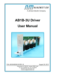
Figure 1: AB5 Driver Box .................................................................................................... 11
Figure 2: AB5 Driver Front Panel ........................................................................................ 14
Figure 3: Differential Analog Input Connection .................................................................... 16
Figure 4: Single-ended (non-differential) Analog Input Connection..................................... 17
Figure 5: Joystick Connection ............................................................................................. 18
Figure 6: Velocity vs. Command Using the AB5/AB51 Driver .............................................. 29
Figure 7: Force vs. Velocity Using the AB5/AB51 Driver at the Various Work Regimes
(a-h) ....................................................................................................................... 30
Figure 8: TP Mechanism Block Diagram ............................................................................. 35
Figure 9: DIP Switch Location inside the AB5/AB51 Driver Box .......................................... 35
Figure 10: DIP Switch Position Map .................................................................................... 36
Figure 11: Thermal Protection Sequence ............................................................................ 38
Figure 12: Opto-Isolated Input Interface .............................................................................. 42
Figure 13: Jumper 2 Configuration ...................................................................................... 43
Figure 14: Layout and Mechanical Dimensions ................................................................... 45
List of Tables
Table 1: Front Panel Connectors ........................................................................................ 15
Table 2: AB5/AB51 Driver Specifications ............................................................................ 26
Table 3: EOP Table for HR Motors Driven by AB5 (Standard LUT) .................................... 30
Table 4: EOP Table for HR Motors Driven by the AB51 Driver (Reduced LUT). ................. 31
Table 5 : Front Panel LED Indicators .................................................................................. 39
Table 6: Control Terminal Block Pinout ............................................................................... 40
Table 7: Motor Output Port Pinout ....................................................................................... 40
Table 8: I/O Port Connector Pinout ..................................................................................... 41
Nanomotion Ltd.
9