1
This document is available at HTTP://WWW.FALCOM.DE/
Falcom STEPP II
Software version 1.6.6
and greater versions
Description
Version 1.02
SOFTWARE 1.6.6 DESCRIPTION
VERSION 1.02
Index of contents
0
OVERVIEW OF DOCUMENT ....................................................4
0.1
RELATED DOCUMENTS ..............................................................................................................5
1
OVERVIEW & FEATURES OF THE SOFTWARE ...........................6
1.1
FEATURES OF THE SOFTWARE .....................................................................................................6
1.2
CONFIGURATION SOFTWARE.....................................................................................................7
1.3
VERSION HISTORY ....................................................................................................................8
1.3.1
1.3.2
Firmware version 1.6.6.......................................................................................................8
Firmware version 1.6.2.......................................................................................................8
2
THE STEPP II STARTERKIT...........................................................9
3
PREPARING TO USE THE HISTORY AND GEO-FENCING
FUNCTIONS ...........................................................................10
3.1
TRACKING ........................................................................................................................... 10
3.1.1
History function ............................................................................................................... 10
3.1.1.1 Filter Settings ............................................................................................................................... 11
3.1.1.2 Configuration examples............................................................................................................ 11
3.1.1.2.1 Examples of history configuration..................................................................................................12
3.1.1.3 How to download the history records ..................................................................................... 12
3.1.1.3.1 NMEA and Binary history data........................................................................................................13
3.2
GEO-FENCING ..................................................................................................................... 14
3.2.1
Configure Geo-fencing................................................................................................. 14
3.2.1.1 How to do Geo-fencing with the STEPP II ................................................................................ 14
3.2.1.2 Determine the Zone’s Grid Coordinates ................................................................................. 14
3.2.1.3 Set up the No-Go Zone Entry event ......................................................................................... 16
4
CONFIGURATION COMMANDS - FOR FALCOM STEPP II ...18
4.1
SMS AND PSRF COMMAND SYNTAX ..................................................................................... 18
4.1.1
SMS Command syntax................................................................................................... 18
4.1.1.1 SMS Command structure .......................................................................................................... 19
4.1.2
NMEA Messages syntax ................................................................................................. 20
4.1.2.1 NMEA messages improved structure ....................................................................................... 21
4.1.3
4.1.4
4.2
Response message structure........................................................................................ 22
Combining commands on the same command line .............................................. 22
NMEA MESSAGES TRANSMITTED/SELECTED BY/TO STEPP II DEVICE .......................................... 23
4.2.1
4.3
Description of NMEA output messages ...................................................................... 23
SUPPORTED PARAMETER ........................................................................................................ 29
4.3.1
4.3.2
4.3.3
4.3.4
4.3.5
4.3.6
4.3.7
4.3.8
4.3.9
4.3.10
NAME................................................................................................................................ 29
PIN..................................................................................................................................... 29
PWD .................................................................................................................................. 30
RING.................................................................................................................................. 31
PORT<index> ................................................................................................................... 31
KEY<index> ...................................................................................................................... 32
IN<index>......................................................................................................................... 33
TEL<index> ....................................................................................................................... 35
VOL ................................................................................................................................... 36
LOG .................................................................................................................................. 36
This confidential document is a property of FALCOM GmbH and may not be copied or circulated without previous permission.
Page 1
SOFTWARE 1.6.6 DESCRIPTION
VERSION 1.02
4.3.11
4.3.12
4.3.13
4.3.14
4.3.15
4.3.16
4.3.17
4.3.18
4.4
ACK................................................................................................................................... 37
GPSRESET.......................................................................................................................... 38
GSMRESET......................................................................................................................... 38
GSMCALL ......................................................................................................................... 39
MSG .................................................................................................................................. 39
GEOMSG.......................................................................................................................... 41
GEO<index> .................................................................................................................... 42
DEL .................................................................................................................................... 43
HOW TO SEND SMS MESSAGE TO THE STEPP II DEVICE ............................................................ 44
4.5
SMS CONFIGURATION COMMANDS– SUPPORTED FROM FIRMWARE 1.6.2................................. 45
4.5.1
4.5.2
4.5.3
4.5.4
4.5.5
4.5.6
4.5.7
4.5.8
4.5.9
4.6
&CNF [PWD] UNIT NAME=VALUE[:NAME=VALUE] Write device configuration ..... 46
&CNF [PWD] PASS Define a password for SMS configuration ................................. 48
&REQ [PWD] POS [n] Request vehicle position with defined period ..................... 48
&REQ [PWD] POS Configure and request vehicle position with defined period . 49
&REQ [PWD] CNF Read the configuration of device............................................... 50
&REQ [PWD] CONNECT Initiate a return call as a data call................................... 50
&REQ [PWD] PHONE<index> [phone] Initiate a listen or voice call ....................... 51
&REQ [PWD] START [latitiude],[longitude] Request vehicle position every
defined period................................................................................................................ 51
&CNF [PWD] WATCH [radious],[text] Set a master region ....................................... 52
NMEA COMMANDS – SUPPORTED FROM FIRMWARE 1.6.2 ..................................................... 54
4.6.1
4.6.2
4.6.3
4.7
$PSRF108,NAME=VALUE[:NAME=VALUE] Write device configuration.................... 54
$PSRF103,[msg],00,[rate],01[*CkSum]<CR><LF> Select protocols to be sent to .. 56
$PSRF109,[data][*ChSum]<CR><LF> Download the history data .......................... 57
GPIOP FORMAT PROTOCOL ................................................................................................. 58
4.8
DESCRIPTION OF THE BINARY FORMAT ..................................................................................... 59
4.8.1
Convert the GPIO hexadecimal value to binary format ......................................... 60
5
HOW TO UPDATE THE NEW FIRMWARE INTO THE STEPP II ...61
6
APPENDIX A ..........................................................................62
6.1
HOW TO CONVERT THE COORDINATES .................................................................................... 62
6.2
THE DIFFERENCE BETWEEN THE VOICE AND ALARM CALLS ......................................................... 63
6.2.1
6.2.2
6.3
Voice channel ................................................................................................................ 63
Alarm channel ................................................................................................................ 63
WHAT TO DO IF THE DEFINED PASSWORD OF DEVICE FAILS ?...................................................... 63
6.4
DEFAULT SETTINGS OF THE FIRMWARE 1.6.5 ............................................................................. 64
6.5
PIN ASSIGNMENTS OF THE XF55-AVL CORRESPONDING TO THE FIRMWARE VERSION 2.0RC1 ..... 64
This confidential document is a property of FALCOM GmbH and may not be copied or circulated without previous permission.
Page 2
SOFTWARE 1.6.6 DESCRIPTION
VERSION 1.02
Version history:
Version number Author
1.00
Fadil Beqiri
Changes
Initial version
- On chapter 4 an important note added.
1.01
-
Manual layout improved, and all SMS commands and
NMEA messages updated.
-
New manual layout.
-
The description of PIN parameter added.
-
Due to the new released firmware version 1.6.6 the
following chapters are added/updated; chapter 1.3
added, chapters 4.3.12 and 4.5.9 updated.
-
Up to 180.000 recordr instead of 100.000 can be stored
into the History.
-
Chapter 6.4 added (default settings of firmware 1.6.6)
-
Chapter 6.5 added.
1.02
Fadil Beqiri
Fadil Beqiri
This confidential document is a property of FALCOM GmbH and may not be copied or circulated without previous permission.
Page 3
SOFTWARE 1.6.6 DESCRIPTION
VERSION 1.02
0 OVERVIEW OF DOCUMENT
Falcom STEPP II is a Plug & Play GSM/GPS device, which contains a software
application that can be configured. The concept of the device is based on a simple
implementation for a wide range of applications with low costs and high flexibility. In
particular it offers a speedy development of systems solutions within the fields of:
-
Fleet management with GPS-location
-
Vehicle security
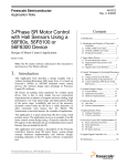
At the core of the above-mentioned system solutions is a classical set-up with clientserver architecture. In this scenario, Falcom STEPP II represents the so-called mobile
client (see image 1).
The integration of Falcom STEPP II requires a clear definition:
•
The characteristics of the integrated software solution of Falcom STEPP II as
a client of the user solution, and the possibilities for configuration.
•
The instruction command for communicating with the client as the main
part of the server application.
•
The hardware interfaces and the respective, necessary installation
guidelines. This part ensures the physical integration of the device to the
target surroundings.
This document seeks to describe the Falcom STEPP II firmware and its possibilities for
configuration.
Furthermore, in this document you will find a detailed description of the instruction
command, providing a foundation for the set-up of own server applications for
communicating with the mobile client (Falcom STEPP II ).
The hardware interfaces and the respective installation guidelines are described in a
separate document (“stepp_II_hardware_manual.pdf”).
This software description reflects Falcom STEPP II’s firmware version 1.6.2 and greater
versions. By using a Falcom SWING it was developed as a communication device
(GSM Modem). However, it can be used with other software compatible GSM
modems such as Falcom A2D-1, SAMBA, TWIST and Falcom TANGO.
In chapter 1 “STEPP II STARTERKIT” you’ll find a reference of the supplied
hardware – components which will support you during the evaluation and
configuration of Falcom STEPP II.
The STARTERKIT contains all hardware and software components required for an
initial start-up and configuration of Falcom STEPP II.
This confidential document is a property of FALCOM GmbH and may not be copied or circulated without previous permission.
Page 4
SOFTWARE 1.6.6 DESCRIPTION
VERSION 1.02
Image 1: Simplified presentation of the AVL client-server architecture.
(Falcom offers a wide variety of GSM modems for enabling
communication on the server side).
GSM modem used on the server side, Falcom recommends:
Falcom SWING-SET
Falcom TANGO
SAMBA
Falcom TWIST
Or other software compatible devices
For more technical details on Falcom products, go to www.falcom.de.
0.1 Related documents
1. SiRF binary and NMEA protocol specification;
www.falcom.de/Service/Manuals/SiRF
2. stepp_II_getting_started.pdf
3. “SteppConfig” Configuration software
4. stepp_II_hardware_manual.pdf
This confidential document is a property of FALCOM GmbH and may not be copied or circulated without previous permission.
Page 5
SOFTWARE 1.6.6 DESCRIPTION
VERSION 1.02
1 OVERVIEW & FEATURES OF THE SOFTWARE
This section tries to explain in general the Falcom STEPP II software (known as
firmware) and its possibilities for configuration.
1.1 Features of the Software
The internal firmware of STEPP II terminal is a fundamental component which in
combination with the excellent hardware performance makes the STEPP II to be on
the top of applications where the fleet management is required. It is an application
designed to be deployed in the field of fleet management. With Falcom STEPP II
terminal running this application mounted in a fleet of vehicles, a remote
administration center is enabled to optimize that fleet’s operations. Of course, it is
also plausible to use the application to monitor stationary devices (such as gas tanks,
industrial machines, etc.).
This application provides the following features:
positioning via GPS
log data to flash memory
download history data via locally or over-air.
remote communications over GSM, more specifically:
SMS message generation and retrieval
data calls (incoming and outgoing)
handling of incoming calls of any type
monitoring of triggers:
general-purpose I/Os (GPIO’s)
ignition lines
activation of general-purpose outputs in a number of ways:
separately activation/deactivation
impulse
periodic
command line interface via locally or (remote) GSM data call, allowing for:
configuration
position, trigger, auxiliary queries
message generation
SIM card access
remote configurability and queries via SMS or GSM data calls
configurable triggered and explicitly requested transmission of:
positional data
trigger status
auxiliary information
periodic transmission
password protection to limit access (both local and remote)
Geo-fencing management, applied to a wide variety of events:
entered/exited/both, in/from marked zones
territory management (up to 99 different zones management)
route verification
This confidential document is a property of FALCOM GmbH and may not be copied or circulated without previous permission.
Page 6
SOFTWARE 1.6.6 DESCRIPTION
VERSION 1.02
arrival/departure notification
prohibited locations
illegal entries
unauthorized movement, and more
All aforementioned feature events can be controlled and GPS position can be
received by means of any GSM phone. You can easily make configuration and
feature changes either locally or over-air. All features can be configured and their
state can be changed using configuration tool (named “SteppConfig”). A brief
description is attached on the next section.
Current position of terminal (i.e. tracks, boats and cars) can be polled remotely over
GSM DATA call.
1.2 Configuration software
For evaluation purposes FALCOM GmbH provides a configuration software which
operates on both Microsoft Windows systems (such as Windows95®, Windows98®,
Windows2000® and WindowsXP®) and GNU/Linux systems, that enables basic
handling and visualization of the remote/local configuration. This configuration
software is included in the delivery pack. The latest released versions of the STEPP II
device firmware, configuration software (named “SteppConfig.exe”) and manuals
can be found on the CD.
With this configuration software it is possible to request GPS position data from the
STEPP II terminal, to trigger its circuit activities, to receive alarm and status reports, as
well as to execute remotely a wide range of configurations. In this case the software
offers an interchangeable client/server communication.
This software can also be used as a configuration manager of the device where the
following settings can be done:
History function (combinations between time, distance and velocity, about
180.000 records possible)
Setting alarm inputs (for each input individually configurable telephone
number, alarm text as SMS, last position)
Automatic tracking (history or current position report by timer or other
event)
Geo-fencing (send report when approaching pre-defined zone
coordinates, deviates off a pre-defined route or detects if a car leaves a
pre-defined country).
Depending on the configuration, the device exchanges data with a server
application (e.g. Mapping-Software, etc.). The STEPP II can be configured by the
user via local RS232-interface or remotely over the GSM (air link).
This confidential document is a property of FALCOM GmbH and may not be copied or circulated without previous permission.
Page 7
SOFTWARE 1.6.6 DESCRIPTION
VERSION 1.02
1.3 Version History
1.3.1 Firmware version 1.6.6
The firmware of Falcom STEPP II is constantly being improved and new features are
added. All commands and parameters having the symbol (1) are available only in
the Firmware 1.6.6 and greater versions.
The following features are improved and new parameters are added:
•
The parameter GPSRESET initiates a Coldstart (feature of the previous
firmware versions) after the user-specified time, if the GPS within that time in
minutes no GPS-fix is obtained. The firmware 1.6.5 and greater versions
initiate a Hotstart (as a default setting) instead of a Cold start that improves
the performance of unit. The default setting of the GPS startup mode can
also be manually changed. To change the default setting the second
parameter <startup_mode> can be specified to: C, W and H
corresponding to the Coldstart, Warmstart and Hotstart respectively.
However, note that the GPSRESET can be sent without specifying the
<startup_mode>. See also the GPSRESET parameter description.
•
To specify a Master region at first you have to specify via the GEOMSG
parameter the phone number where the message (text specified on the
&CNF WATCH) has to be sent and then the &CNF WATCH with userspecified value can be sent to the target STEPP II device. In the firmware
1.6.5 and greater versions the GEOMSG settings are built-in the &CNF
WATCH as one line (command). The purpose of this command is to save
the end user time and simplify the configuration of a Master region. Once
a Master region is configured, all user-defined parameter are performed
and implemented. If the Master region is cleared (by sending the
command &CNF WATCH 0), it does not mean that the GEOMSG settings
will automatically be cleared. The GEOMSG settings can only be cleared
separately, if these settings are no more required by the user (since these
settings may still be used for other geofencing regions), by sending the
command (&CNF UNIT GEOMSG) without parameter entry to the target
device. See also the description in chapter 4.5.9.
1.3.2 Firmware version 1.6.2
Initial firmware version for the STEPP II device.
This confidential document is a property of FALCOM GmbH and may not be copied or circulated without previous permission.
Page 8
SOFTWARE 1.6.6 DESCRIPTION
VERSION 1.02
2 THE STEPP II STARTERKIT
Refer to the “stepp_II_getting_started.pdf” user manual.
This confidential document is a property of FALCOM GmbH and may not be copied or circulated without previous permission.
Page 9
SOFTWARE 1.6.6 DESCRIPTION
VERSION 1.02
3 PREPARING TO USE THE HISTORY AND GEOFENCING FUNCTIONS
3.1 Tracking
3.1.1 History function
The History memory enables the receiver to store position, time and events in the onboard flash memory. When receiving valid GPS protocols, Falcom STEPP II is capable
of saving up to 180.000 GPS protocols in its history memory.
When the memory space has been used up, the oldest protocols will automatically
be deleted to make space for new incoming data (FIFO principle).
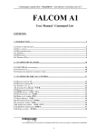
Image 3 shows a logical flow chart, for better understanding how Falcom STEPP II
saves history data.
History
History- -Filter
Filter
No
No
Fix
FixPosition
Position
enable
enable? ?
Yes
Yes
No
No
X*X*
SV
SVsolution?
solution?
Yes
Yes
No
No
>Min
>Min
Time?
Time?
Yes
Yes
No
No
No
No
End
End
>Min
>Min
Distance?
Distance?
>Max
>Max
Time?
Time?
Yes
Yes
No
No
End
End
>Max
>Max
Distance?
Distance?
Yes
Yes
No
No
>Max
>Max
Speed?
Speed?
End
End
Yes
Yes
Yes
Yes
No
No
>Min
>Min
Speed?
Speed?
Yes
Yes
Store
Storedata
dataon
on
Flash
Flashmemory
memory
*)*) XX>=
>=3;
3;
END
END
Image 3: History Filter
This confidential document is a property of FALCOM GmbH and may not be copied or circulated without previous permission.
Page 10
SOFTWARE 1.6.6 DESCRIPTION
VERSION 1.02
Taking the illustrated logic into consideration, several varieties of saving history data
are possible.
3.1.1.1
Filter Settings
By configuring supplementary filters, the history function offers the possibility to
reduce the number of stored data records. These filters prevent the history from
storing unnecessary data, e.g. if a vehicle is not moving.
To set these filters, a configuration command can be sent to the device either locally
(by connecting the device to a PC, whereby only NMEA messages are available for
use) or over-air (GSM network, whereby both SMS commands and NMEA messages
can be set via SMS).
3.1.1.2
Configuration examples
The following will explain the used filters for time, distance and speed.
The respective minimum values for time, speed and distance have an ANDConjunction, meaning that if only value does not apply, then all three values are
ignored and not saved in the history.
The maximum values have an OR-Conjunction. If one of the maximum parameters
has been met, the GPS protocols will be saved in the history.
In accordance with the above flow chart, either all minimum parameters or just one
maximum parameter have to be exceeded, and the NMEA protocols are stored in
the history.
Parameter explanation:
The parameters used in examples below such as the FixMin Time, FixMax
Time, Dist.Min, Dist.Max, SpeedMin and Speed Max correspond to the
<fmin>, <fmax>, <dmin>, <dmax>, <smin> and <smax> used in the SMS
commands and NMEA messages respectively.
Minimum (lowest value)
Time filter
Distance filter
Speed filter
Maximum (highest value)
FixMinTime (Seconds)
FixMaxTime (Seconds)
AND
OR
Dist.Min (Meters)
Dist.Max (Meters)
AND
OR
SpeedMin (km/h)
SpeedMax (km/h)
Combination of both
OR
Storing of protocol
Table 1: Conditions for saving data in the history
Logs every 10 sec.
Logs every 100 m
Logs every second at
speed ≥ 40 km/h
FixMin
Time [s]
0
0
FixMax
Time [s]
10
0
Dist.
Min[m]
0
0
Dist.
SpeedMin Speed
Max [m] [km/h]
Max [km/h]
0
0
0
100
0
0
0
0
0
0
0
40
Table 2: Programming example
This confidential document is a property of FALCOM GmbH and may not be copied or circulated without previous permission.
Page 11
SOFTWARE 1.6.6 DESCRIPTION
VERSION 1.02
3.1.1.2.1 Examples of history configuration
When history logging is enabled and the minimum number of satellites is visible (not
included in tables below), history records will be stored depending on the time,
distance and speed conditions. The history records would be stored in the NMEA
format as specified in Section 4.2.1. Below are some configuration examples, which
can be sent to the STEPP II device as a command via SMS or using the NMEA
messages, sent locally to the device.
Example 1
Record every 50 m if the vehicle has a speed less then 25 km/h
Record every 2 sec. if the vehicle is moving at a speed between 25
and 50 km/h
Record every second if the vehicle is driving faster than 50 km/h
Example 1, settings
SMS command
NMEA message
FixMin
FixMax
Dist.Min Dist.Max SpeedMin Speed
Time [s] Time [s] [m]
[m]
[km/h]
Max [km/h]
2
0
0
50
25
50
&CNF [PWD] UNIT MSG=S132345678,4,2,0,0,50,25,50,RMCIOP
$PSRF108,LOG=4,2,0,0,50,25,50*7A
Example 2
Record every 50m if the vehicle is driving faster than 25 km/h
Example 2, settings
SMS command
NMEA message
FixMin
FixMax
Dist.Min Dist.Max SpeedMin Speed
Time [s] Time [s] [m]
[m]
[km/h]
Max [km/h]
0
0
50
0
25
0
&CNF [PWD] UNIT MSG=S132345678,4,0,0,50,0,25,0,RMCIOP
$PSRF108,LOG=4,0,0,50,0,25,0*4D
Example 3
Record every 2 sec. if the vehicle is moving at a speed between 25
and 50 km/h
Example 3, settings
SMS command
NMEA message
FixMin
FixMax
Dist.Min Dist.Max SpeedMin Speed
Time [s] Time [s] [m]
[m]
[km/h]
Max [km/h]
2
0
0
0
25
50
&CNF [PWD] UNIT MSG=S132345678,4,2,0,0,0,25,50,RMCIOP
$PSRF108,LOG=4,2,0,0,0,25,50*4F
Example 4
Record every second if the vehicle is driving faster than 50 km/h
Example 4, settings
SMS command
NMEA message
3.1.1.3
FixMin
FixMax
Dist.Min Dist.Max SpeedMin Speed
Time [s] Time [s] [m]
[m]
[km/h]
Max [km/h]
0
0
0
0
0
50
&CNF [PWD] UNIT MSG=S132345678,4,0,0,0,0,0,50,RMCIOP
$PSRF108,LOG=4,0,0,0,0,0,50*7A
How to download the history records
Stored GPS history data can be retrieved either locally (via serial link) or remotely (via
data connection). An executable command, see chapters 4.6.3, can be sent to the
device either locally or over-air (after a data call is established, a NMEA message
can be sent to the STEPP II device).
This confidential document is a property of FALCOM GmbH and may not be copied or circulated without previous permission.
Page 12
SOFTWARE 1.6.6 DESCRIPTION
VERSION 1.02
Please, refer to the used terminal program, how to capture the incoming data into a
*.log file format.
After the GPS history data are successfully downloaded and captured into a file on
PC, the evaluation of the stored records can be performed using mapping software
(Map&Guide or another one) and a suitable user developed program (the user
developed program reads the GPS data position from the stored *.log file and sent
them to a COM port where the Map software is connected). To do this, open the
map software and select and select the COM port where the data will be read. Start
the user developed program and sent the read data from the *.log file to the COM
port where the Map software is connected. The route by means of the GPS data
position from the selected file is being displayed in the map.
Please note that, if the stored records are in the binary format, they could not be
accepted from the mapping software. A description about this format is attached in
chapter 4.8.
3.1.1.3.1 NMEA and Binary history data
The stored position data in NMEA format begins with $GPLOG,1,….. and ends with
$GPLOG,0,….. indicating the start date/time (29 October 2004 08:51:06) and end
date/time (29 October 2004 11:53:14). All records between the start and end records
include the stored GPS position data. A description about the NMEA messages is
attached in chapter 4.2.1
The stored position data in binary format also begins with $GPLOG,1,….. and ends
with $GPLOG,0,….. indicating the start date/time (29 October 2004 08:51:06) and
end date/time (29 October 2004 11:53:14). All record data between the start and
This confidential document is a property of FALCOM GmbH and may not be copied or circulated without previous permission.
Page 13
SOFTWARE 1.6.6 DESCRIPTION
VERSION 1.02
end lines include the stored GPS data in the binary format. A description about this
format is attached in chapter 4.8. This format offers a maximum data compression.
3.2 Geo-fencing
3.2.1 Configure Geo-fencing
This section describes how the Geo-fencing works and how to set up a No-Go Zone
Entry event to the terminal, it is assumed that the users have a basic understanding
of conditional logic and geographic coordinates.
The term “No-Go Zone Entry” used in the manual, signifies defined customer area(s)
on which configuration of events are possible.
3.2.1.1
How to do Geo-fencing with the STEPP II
The Geo-fencing is a term used to describe an event when the vehicle fited with a
GSM/GPS unit places an electronic rectangle coordinates around your vehicle.
Once a geo-fence is established, users can be automatically notified, as a result of
exception reporting, if a vehicle enters and/or leaves the user pre-defined area(s).
This functionality can be used for territory management, route verification,
arrival/departure notification and prohibited locations. Exception reporting can also
be applied to a wide variety of additional events, such as arrivals, departures,
deliveries, pick-ups, illegal entries, unauthorized movement, and more. The STEPP II
terminal based on the GPS system, recognizes if the vehicle crosses a user-defined
geographic boundary, therefore, a SMS alert is issued. The constructed form of
geographic boundary zones (restricted customer areas) is rectangular ones and
they can be in different sizes, but the smallest size is 30 x 30 meters recommended.
The figure below shows possibilities of defining geographic zones.
3.2.1.2
Determine the Zone’s Grid Coordinates
The STEPP II firmware supports three different kinds of coordinate format for latitude
and longitude. These formats are based on the output of NMEA protocol format. So
the coordinates may be one of the following types:
This confidential document is a property of FALCOM GmbH and may not be copied or circulated without previous permission.
Page 14
SOFTWARE 1.6.6 DESCRIPTION
•
VERSION 1.02
Latitude, longitude(in degrees, minutes, seconds).
-
•
$GPRMC,141038.641,A,50'42'44",N,10'52'55",E,0.08,17.08,280104,,*09
Latitude, longitude (in decimal degrees).
•
$GPRMC,141128.638,A,50.712222,N,10.881944,E,0.07,103.22,280104,,*3E
Latitude, longitude (GPS NMEA format).
-
$GPRMC,141037.641,A,5042.5103,N,1052.0101,E,0.09,13.54,280104,,*0E
First, you have to use your mapping software (Map&Guide or another one) to
determine the rectangle coordinates for your set zone. In order to do this, open the
map software and locate the coordinate text that displays the geographic
coordinates of your cursor location on the map:
For the Map&Guide, by moving the mouse cursor on the map the current
coordinates (Longitude/Latitude in degrees, minute and second) are displayed at
the bottom corner on the first panel of the viewer window.
Locate the zone you want to define on the map, and note down the upper left
corner (UL) and the lower right corner (LR) coordinates of a rectangle that defines
the zone, as shown in figure below.
In our example (in degrees, minutes, seconds):
-
Latitude (UL) = 10°52’55” N
-
Longitude (UL) = 50°42’44” W
-
Latitude (LR) = 10°57’14” N
-
Longitude (LR) = 50°40’18” W
The coordinates can also be defined in other formats (Map&Guide uses
degrees and decimal minutes notation).
In order to convert coordinates from degrees, minutes, seconds format to decimal
format, refer to chapter 6.
You have now determined the grid coordinates for your rectangular zone. One last
step before setting up the event, is to determine the sign of the coordinate values.
Please remember that, Latitude North and Longitude East are positive and Latitude
South and Longitude West are negative (see figure below):
This confidential document is a property of FALCOM GmbH and may not be copied or circulated without previous permission.
Page 15
SOFTWARE 1.6.6 DESCRIPTION
3.2.1.3
VERSION 1.02
Set up the No-Go Zone Entry event
Set up the event as normal, and enter the parameters as indicated in chapter 4.3.17.
&CNF UNIT GEO<index>=<reg_name>,<reg_id>,<long_UL>,<lat_UL>,<long_LR>,<lat_LR>,
<when>
&CNF UNIT GEO01=Ilmenau,01,50.7122,10.8819,50.6716,10.9538,0
$PSRF108,GEO01=Ilmenau,01,50.7122,10.8819,50.6716,10.9538,0*1A
For our example:
This will result in an event being recorded in the STEPP II when the Latitude of the
vehicle’s current position is bigger than 10°57’14” AND smaller than 10°52’55”AND
the Longitude of the vehicle’s current position is bigger than 50°42’44” AND smaller
than 50°40’18”. That means the FALCOM STEPP II will send a SMS alert message if a
vehicle leaves that defined zone.
Concerning the set No-Go Zone Entry event, the STEPP II terminal supports three
different configuration types:
1 - if the vehicle enters the pre-defined zone.
2 - if the vehicle leaves the pre-defined zone.
3 - if the vehicle enters and leaves the pre-defined zone.
The other possibility is also supported, when the user sets up to 99 different zones with
the same ID number. The STEPP II recognises those restricted zones as a single zone.
The set up of zones has to be adjacent to or overlapped zones (no free space
between zones). That means if the vehicle leaves the first zone and at the same time
enters to the next one and others, (depending on the amount of set zones) the STEPP
II compares the ID zones (the previous zone with the next one) if they correspond, no
SMS message will be sent. When the vehicle leaves the current zone and does not
contemporaneously enter to the next one, so a SMS alert message with
corresponding zone identification text will be sent to the predefined phone number.
In other words this geo-fencing feature allows you to establish an area where the
vehicle can travel. If the vehicle travels outside this area, an exception report is sent
to the target phone number.
Now simply download the new configuration to the vehicle by sending the commad
in table above, and your STEPP II unit will start recording events based on the defined
geographic zone.
The STEPP II device can store up to 100 regions, one of which is the
master region. The master region is pre-defined and is not configurable
by a direct connected STEPP II , but it can be activated and
deactivated by using the SMS messages (refer to the chapter 4.5). The
area indicator of master region is “00”.
This confidential document is a property of FALCOM GmbH and may not be copied or circulated without previous permission.
Page 16
SOFTWARE 1.6.6 DESCRIPTION
VERSION 1.02
In order to configure the STEPP II remotely via SMS or data connection, please, refer
to the chapters 4.5 and 4.6, a comprehensive description is also added.
After the user has defined and activated geo-fencing zone(s), and then
the STEPP II device is switched off; in the next start-up, STEPP II compares
its obtained valid position with the positions of activated geo-fencing
zone(s). If they are identical (means, within the activated area), a SMS
will be sent to the target phone number specified on the GEOMSG
parameter.
This confidential document is a property of FALCOM GmbH and may not be copied or circulated without previous permission.
Page 17
SOFTWARE 1.6.6 DESCRIPTION
VERSION 1.02
4 CONFIGURATION COMMANDS - FOR FALCOM
STEPP II
This chapter explains the configuration commands for Falcom STEPP II.
There are two categories of configuration commands:
•
Commands for SMS remote configuration
•
Commands for direct configuration of a Falcom STEPP II connected to
software “SteppConfig”
In Table 3 you will find an overview of the commands for SMS remote configuration
of a Falcom STEPP II.
Important:
Take into account, that all configuration commands sent to the STEPP II (via SMS,
data connection or locally) should match exactly the parameter format (Syntax)
described in this manual.
!!! Note that incorrect assigned parameters into a configuration command may
carry the STEPP II device into the instability conditions (such as the STEPP II could
not be available, could not pick up a voice call etc.) and its configuration can
only locally be improved (via a direct connected STEPP II device).
4.1 SMS and PSRF Command syntax
4.1.1 SMS Command syntax
The SMS commands can be sent to the device same as a SMS text, but their format
have to be considered. The "&CNF" or "&REQ" command header must be set at the
beginning of each command line. In commands described below, the SMS
password is indicated as [PWD] enclosed in square brackets or PWD, indicating that
it is an optional field.
Types of SMS commands:
Command type
Syntax
Readable command
&REQ [PWD] CNF
Writable command
Executable command
Clear Command
&CNF [PWD] UNIT
<Parameter_name>=<value>
&CNF [PWD]
<Parameter_name> <value>
&CNF [PWD]
<Parameter_name>
Function
This command returns the current set
value of the parameter or parameters.
This command sets user-definable
parameter values.
This command performs an event to
the device.
This command deactivates that
parameter name (deletes the value(s))
which previously has (have) been
specified.
This confidential document is a property of FALCOM GmbH and may not be copied or circulated without previous permission.
Page 18
SOFTWARE 1.6.6 DESCRIPTION
4.1.1.1
VERSION 1.02
SMS Command structure
In the table below you will find two types of the SMS commands, which can be sent
to the STEPP II device.
The SMS command including the parameter [PWD] has to be used, if
the parameter [PWD] is already specified, otherwise the device will
not accept commands without entering that password.
The SMS command excluding [PWD] parameter can be used, if the
[PWD] parameter is empty (not specified from the user).
All SMS commands have to be sent in uppercase (capital letters), otherwise, the
configuration could not be accepted. If a sent command (via SMS, data
connection or locally) is incorrectly typed (based on the structure in the table below)
by the user, the device ignores (refuses) that command and no configuration is
performed or you may carry the STEPP II device into the instability conditions.
If more than one parameter (combining commands on the same writable
command line) should be sent within a command (SMS message), they should be
separated by colons “:” (indicated as [:]). The square brackets have to be omitted
when you input that command.
IIf a command (message including one of the parameter names
<Parameter_name>) is sent without value then the corrent status (value) of that
parameter stored into the FLASH memory will be deleted (deactivated), except the
“&REQ<space>CNF” read command.
The <space> string included in the command structure indicates that the command
header and/or parameter has to be separated by spaces (“ “).
Do not use the quotation marks if a <value> is a character string, e.g. <text>.
Types of SMS commands:
Command type
Readable command
Writable command
Combining commands on
the
same writable
command line
Executable command
Structure
&REQ<space>[PWD]<space>CNF
or
&REQ<space>CNF
&CNF<space>[PWD]<space>UNIT<space> <Parameter_name>=
<value>,<value>,….<value>
or
&CNF<space>UNIT<space> <Parameter_name>=<value>,<value>,
….<value>
&CNF<space>[PWD]<space>UNIT<space> <Parameter_name>=
<value>,<value>,….<value>[:] <Parameter_name>=<value>,
<value>,….<value>[:]
….
or
&CNF<space>UNIT<space>
<Parameter_name>=<value>,<value>,….<value>[:]
<Parameter_name>=<value>, <value>,….<value>[:]
….
&CNF<space>[PWD]<space>
<Parameter_name><space> <value>,<value>,….<value>
or
&CNF<space>
<Parameter_name><space><value>,<value>,….<value>
This confidential document is a property of FALCOM GmbH and may not be copied or circulated without previous permission.
Page 19
SOFTWARE 1.6.6 DESCRIPTION
VERSION 1.02
&CNF<space>[PWD]<space><Parameter_name>
or
&CNF<space><Parameter_name>
Clear Command
4.1.2 NMEA Messages syntax
The NMEA message can be sent to the remote device same as a SMS text, but the
format of these messages has to be considered. The "$PSRF<m_id>" NMEA command
must be set at the beginning of each command line. The last two characters
<CR><LF> are "control" characters and are not normally printed (for this reason they
are customarily shown enclosed in brackets.
The NMEA standard message has the following formats and in this format it will also
be accepted by the STEPP II device:
Command
$PSRF<m_id>
Parameter
<Date>
Checksum
<*CKSUM>
End Sequence
<CR><LF>
The $PSRF message header and the parameter <m_id> message identifier create a
NMEA command.
The parameter <Date> can contain different valid parameters, which are supported
by the STEPP II device.
The checksum <*CKSUM> consists of a “*” character followed by two hex values.
In order to calculate the Checksum, use your own application. Below a small
source code written in Visual Basic:
{*****************************************}
Public Sub CheckSum(field As String)
If field = “” then CS = “*”
CS = 0
For i = 1 to Len(field)
CS = CS Xor Asc(Mid$(field, i, 1))
Next
CS = Hex(CS)
If Len(CS) =1 then
CS = “0” & CS
CS = “*” & CS
END SUB
{*****************************************}
Therefore, the string over which the checksum has to be calculated is:
field = PSRF<m_id>,<data>
excluding “$”character.
All fields in all proprietary NMEA messages are required, none are optional.
All NMEA messages are comma delimited “,”.
Types of NMEA messages:
NMEA
Syntax
Message type
Selectable
message
$PSRF103,<msg>,00,<rate>,01
<*CkSum><CR><LF>
Function
This NMEA message select the supported
messages which can be polled once, or
set up periodically.
This confidential document is a property of FALCOM GmbH and may not be copied or circulated without previous permission.
Page 20
SOFTWARE 1.6.6 DESCRIPTION
Writable
message
Executable
message
4.1.2.1
$PSRF108,<Parameter_name>
=<value><*CkSum><CR><LF>
$PSRF109,<r_data>,<s_date>,
<s_time>,<e_date>,<e_time>
<*CkSum><CR><LF>
VERSION 1.02
This NMEA message sets user-definable
parameter values.
This NMEA message sets user-definable
parameter values to download the stored
history data.
NMEA messages improved structure
All NMEA messages have to be sent in uppercase (capital letters) otherwise the
configuration could not be accepted. If a send message (via SMS, data connection
or locally) is incorrectly typed by the user (based on the structure in the table below),
the device ignores (refuses) that command and no configuration is performed. Due
to the incorrectly typed of NMEA message you may carry the STEPP II device into the
instability conditions.
If more than one parameter (combining message on the same writable message
line) has to be sent within a command (NMEA message), they should be separated
by colons “:” (indicated as [:]). The square brackets have to be omitted when you
input that command.
If a parameter <parameter_name> of NMEA message is sent without value to the
device then this parameter is deactivated by setting an undefined value.
Different from the SMS command, the parameters of NMEA message are not
separated by spaces (“ “).
The Falcom STEPP II acceptes following formats:
Command type
Selectable Message
Writable Message
Combining message on
the same writable
message line
Executable message
Structure
$PSRF103,<msg>,00,<rate>, 01<*CkSum><CR><LF>
$PSRF108,<parameter_name>=<value><*CkSum><CR><LF>
$PSRF108,<parameter_name>=<value>,<value>,….<value>[:]
<parameter_name>=<value>,<value>,….<value>[:]…
<*CkSum><CR><LF>
$PSRF109,<r_data>,<s_date>,<s_time>,<e_date>,<e_time>
<*CkSum><CR><LF>
This confidential document is a property of FALCOM GmbH and may not be copied or circulated without previous permission.
Page 21
SOFTWARE 1.6.6 DESCRIPTION
VERSION 1.02
4.1.3 Response message structure
A SMS alarm report is presented in numeric and/or text format, which includes the
parameters, marked with blue colour listed in the table below. An improved
description including an example is attached in the table 4.
If the responded message does not fit in (due to limited text length within a SMS of
160 characters) one SMS message, it is sent in several SMS messages. In this case,
CNF is replaced by CNFxx, where xx is the message index starting from 00. In the last
message, CNF is replaced by ENDxx. See the Example 2 in table below.
Types of response message:
Respond
Structure
message type
+CMT: <SMS header>
<device_name><space>END<index><space>
<parameter_name>=<configuration>
or
+CMT: <SMS header> <device_name><space>CNF<index><space>
From read
<parameter_name>=<configuration>
command
…
…
…
+CMT: <SMS header> <device_name><space>END<index><space>
<parameter_name>=<configuration>
stepp_II CNF01
NAME=stepp_II:LOG=3,1,900,0,0,0,0:GEO01=Langewiesen,1,5041
stepp_II CNF02 PIN=1111:NMEA=9600-8N1,GGA.1,GLL.1,GSA.1,
GSV.1,RMC.1,IOP.1,GS
Example 1
stepp_II CNF03 PORTS=P1#E,0,0,P2#Z,5,5,P3#A, 0,0,P4#A,0,0:UNIT=FAL
STEPP V1.6.2
stepp_II END04 GPSFIX=5040.4012 1058.8418 782464386 3976357 771535
4910975
From
execution
<device_name><space><alarm_text><CR><LF> <first_protocol><CR><LF>
command
<second_protocol><CR><LF>
(if an alarm is
triggered)
<device_name>alfa_car<alarmtext>AlarmImput1<CRLF>
<first_protocol> $GPRMC,103530.000,A,5040.3986,N,01058.8636,
Example 2
E,0.06,171.45,290903,,*04<CRLF>
<second_protocol>$GPIOP,11000001,00010000,4.82,3.69,4.06*72
4.1.4 Combining commands on the same command line
You may enter several SMS commands or NMEA messages on the same line. This
eliminates the need to type the message header or NMEA message before each
parameter configuration. Instead, it is only needed once at the beginning of the
command line. Use a colon “:” as command delimiter.
The command line buffer accepts a maximum of 160 characters due to the SMS
limitation of 160 characters. If this number is exceeded, the sent commands will be
ignored from the STEPP II device or ERROR is returned.
This confidential document is a property of FALCOM GmbH and may not be copied or circulated without previous permission.
Page 22
SOFTWARE 1.6.6 DESCRIPTION
VERSION 1.02
4.2 NMEA messages transmitted/selected by/to STEPP II
device
The STEPP II device transmits NMEA sentences every second, depending on the
configuration. The identifiers for the NMEA messages transmitted by the STEPP II
device are listed below. Excepting GPIOP and GPGSM all other messages are based
on the NMEA standard messages.
GPGGA
GPS Fix Data
GPRMC
Recommended Minimum Specific GPS Data
GPGSV
GPS Satellites in View
GPGSA
GPS DOP and Active Satellites
GPGLL
Geographic Position in Latitude/Longitude.
GPIOP
STEPP II Device Input/Output Ports
GPGSM
STEPP II Device GSM Status.
A full description and definition of the listed NMEA messages is provided in the next
subsection of this section.
4.2.1 Description of NMEA output messages
The following table is intended as a quick reference to explain the formats used in
the tables below.
Format
hhmmss.ss
ddmmyy
ddmm.mmmm
dddmm.mmmm
dd.dddddd
dd'mm'ss"
x
xx
x.x
hh
bbbbbbbb
a
"a"
<CR><LF>
Description
Time: hh hours, mm minutes, ss.ss seconds.
Date: day dd, month mm, year yy.
Latitude: dd degrees, mm.mmmm minutes.
Longitude: ddd degrees, mm.mmmm minutes.
Latitude/longitude: dd.dddddd degrees.
Latitude/longitude: dd degrees, mm minutes, ss seconds
Integer.
Integer having exactly two digits (using leading zeros).
Number including fraction.
Two-digit hexadecimal number (using uppercase A–F).
Eight-digit binary number.
ASCII text.
ASCII text in quotation marks.
Carriage return and line feed.
The $GPGGA message includes time, position, GPS quality and number of satellites in
use.
Example:
$GPGGA,133726.569,5040.4365,N,01058.5646,E,1,03,8.9,92.9,M,,,,0000*3F
Field
1
Format
$GPGGA
Example
$GPGGA
Description
Start of sentence
2
hhmmss.ss
133726.569
UTC time
3
ddmm.mmmm
5040.4365
Latitude
4
a
N
Latitude direction (N/S)
5
dddmm.mmmm
01058.5646
Longitude
This confidential document is a property of FALCOM GmbH and may not be copied or circulated without previous permission.
Page 23
SOFTWARE 1.6.6 DESCRIPTION
VERSION 1.02
6
a
E
Longitude direction (W/E)
7
x
1
8
xx
03
GPS fix quality:
0: invalid
1: GPS fix
2: DGPS fix
Number of satellites in use
9
x.x
8.9
10
11
12
13
14
15
16
17
x.x
M
x.x
M
x
xxxx
*hh
<CR><LF>
92.9
M
0000
*3F
Horizontal dilution of precision (relative
accuracy of horizontal position)
Altitude above mean sea level (geoid)
Altitude units (meters)
Height of geoid above earth ellipsoid
Geoid height units (meters)
Time since last DGPS update (seconds)
DGPS reference station ID
Checksum
End of message termination
Table 1: The GPGGA message data format.
The $GPRMC message includes time, date, position, course and speed data.
Example:
$GPRMC,133725.569,A,5040.4365,N,01058.5650,E,0.05,302.98,251004,,*00
Field
1
2
3
Format
$GPRMC
hhmmss.ss
a
Example
$GPRMC
133725.569
A
4
5
6
7
8
9
10
11
12
13
14
ddmm.mmmm
a
dddmm.mmmm
a
x.x
x.x
ddmmyy
x.x
a
*hh
<CR><LF>
5040.4365
N
01058.5650
E
0.05
302.98
251004
*00
Description
Start of sentence
UTC time
Position validity (A: valid, V: invalid or S*: Last stored
valid position)
Latitude
Latitude direction (N/S)
Longitude
Longitude direction (W/E)
Speed (knots)
Heading (degrees)
Date
Magnetic variation (degrees)
Magnetic variation direction (W/E)
Checksum
End of message termination
Table 2: The GPRMC message data format.
_______________________________________________________________________________
*
This remark is a reference from description of $GPRMC and $GPGLL
messages, only. The STEPP II device will store the latest valid GPS fix. In
case of user requests the vehicle position and the up to date position of
the device is invalid, the device holds the latest stored valid GPS fix
(longitude, latitude and altitude) and sends it to the target phone
number in a string formatted as shown below. The validity status
indicator in capital letter inside the $GPRMC and $GPGLL protocols will
be switched from V to S –letter.
This confidential document is a property of FALCOM GmbH and may not be copied or circulated without previous permission.
Page 24
SOFTWARE 1.6.6 DESCRIPTION
VERSION 1.02
Example:
Send:
&REQ PWD POS 0
//The user request of vehicle position was at 12:39:55.
Receive:
$GPRMC,094055.121,S,5040.4014,N,01058.8657,E,,,280103,,*16
//a RMCprotocol will be sent to the message sender with switched
status indicator from “V” to “S”. The attached time (the UTC time
between the message header and status indicator) does not
correspond to the time of position request (current time). The latest
valid GPS position holds form storage will be sent to the SMS receiver
including the recorded time (e.g. 09:40:55).
The received $GPRMC message above that is sent to the SMS receiver instead of
the device sends an invalid GPS position as below:
Receive:
$GPRMC,123955.221,V,0000.0000,N,00000.0000,E,,,280103,,*34
This feature allows the user of the device to calculate the time on which the
device has not been able to obtain the location fix. In this case the calculation
time of the invalid GPS position is 02 hours and 59 minutes.
________________________________________________________________
The $GPGSV includes the number of satellites in view satellite ID numbers and their
elevation, azimuth and signal-to-noise ratio.
Example:
$GPGSV,3,1,10,05,79,067,39,30,63,277,35,14,37,269,,09,36,145,*78
$GPGSV,3,2,10,24,28,098,36,06,24,212,,04,24,058,29,17,16,129,*7F
$GPGSV,3,3,10,01,13,328,34,25,05,311,*74
Field
1
2
3
4
5
6
7
8
9
10
11
12
13
Format
$GPGSV
x
x
xx
xx
xx
xxx
xx
*hh
<CR><LF>
Example
$GPGSV
3
3
10
01
14
328
34
25
05
311
*74
Description
Start of sentence
Number of messages (1 to 3)
Message number (1 to 3)
Number of satellites in view (1 to 12)
Satellite PRN number
Satellite elevation (degrees) (00 to 90), may be null
Satellite azimuth (degrees) (000 to 359), may be null
Satellite signal to noise ratio in dB (00 to 99), may be null
Similar to 5–8 for next satellite, may all be null
Similar to 5–8for next satellite, may all be null
Similar to 5–8 for next satellite, may all be null
Checksum
End of message termination
Table 3: The GPGSV message data format.
This confidential document is a property of FALCOM GmbH and may not be copied or circulated without previous permission.
Page 25
SOFTWARE 1.6.6 DESCRIPTION
VERSION 1.02
The $GPGSA message includes the list of satellites being used.
Example:
$GPGSA,A,2,05,09,04,,,,,,,,,,13.4,8.9,10.0*3D
Field
1
2
Format
$GPGSA
a
Example
$GPGSA
A
3
x
2
4
xx,xx, . . .
05
5
6
7
8
9
x.x
x.x
x.x
*hh
<CR><LF>
13.4
8.9
10.0
*3D
Description
Start of sentence
Operating mode:
M:
Manual, operate in 3-D mode.
A:
Automatically choose 2-D or 3-D mode.
Fix mode:
1:
Fix not available
2:
2-D fix
3:
3-D fix
PRN numbers of satellites in use (unused fields
null)
Position dilution of precision
Horizontal dilution of precision
Vertical dilution of precision
Checksum
End of message termination
Table 4: The GPGSA message data format.
The $GPGLL message includes the latitude, longitude, UTC time of position fix and
status..
Example:
$GPGLL,5040.4025,N,01058.8342,E,113704.665,A*32
Field
1
2
3
4
5
6
7
8
9
Format
$GPGLL
ddmm.mmmm
a
dddmm.mmmm
a
hhmmss.sss
a
*hh
<CR><LF>
Example
$GPGLL
5040.4025
N
01058.8342
E
113704.665
A
*32
Description
Start of sentence
Latitude
Latitude direction (N/S)
Longitude
Longitude direction (W/E)
UTC Position
Position validity (A: valid, V: invalid or S*: invalid)
Checksum
End of message termination
Table 5: The GPGLL message data format.
The $GPIOP message includes the status of the digital/analogue inputs and output
ports. A detailed description is also attached in chapter 4.7.
Example:
$GPIOP,01000000,00000000,0.28,0.28,4.15*72
Field
1
2
Format
$GPIOP
bbbbbbbb
Example
$GPIOP
01000000
Description
Start of sentence
Inputs:
8–1 (1: on, 0: off)
1–4:
Inputs 1–4
5–6:
Unused
7:
Car battery status
This confidential document is a property of FALCOM GmbH and may not be copied or circulated without previous permission.
Page 26
SOFTWARE 1.6.6 DESCRIPTION
VERSION 1.02
3
bbbbbbbb
00010000
4
5
6
7
8
x.x
x.x
x.x
*hh
<CR><LF>
0.28
0.28
4.15
*72
8:
Outputs:
1–4:
5 :
Ignition status
8–1 (1:on, 0: off)
Outputs 1–4
always is set to 1, indicates the
outputs are operational.
6–8:
Unused
Analog input 1 (V)
Analog input 2 (V)
Backup battery level (V)
Checksum
End of message termination
Table 6: The GPIOP message data format.
The $GPGSM message includes the GSM operator and reception status. Keep in
mind that the GPGSM message can be sent in one of three different modes. The first
parameter after the message header $GPGSM identifies the mode on which the
device is currently processing. Each of the following tables, recognizing the GPGSM
message, specifies one of three modes.
In the $GPGSM message the number of the caller will also be transmitted if the caller
number is not available in the access/authorization list.
Table below shows the mode 0 which indicates that the sentence gives the GSM
module status.
Example:
$GPGSM,0,1,0,"T-Mobile D",20,5518,4caa*32
Field
1
2
3
4
5
6
Format
$GPGSM
x
b
x
"a"
xx
Example
$GPGSM
0
1
0
"T-Mobile D"
20
7
8
9
10
a
a
*hh
<CR><LF>
5518
4caa
*32
Description
Start of sentence
GSM status mode: 0
Registration (1:registered, 0: unregistered)
GSM status
Network operator name
GSM field strength (0 to 31) 0: $-$113 dB 31: $-$51
dB
Area code
Cell ID
Checksum
End of message termination
Table 7: The GPGSM message data format in GMS status mode.
Table below shows the mode 1 which indicates that an SMS message was received.
Example:
$GPGSM,1,+490172123456,"","My Message"*54
Field
1
2
3
4
5
6
7
Format
$GPGSM
x
a
"a"
"a"
*hh
<CR><LF>
Example
$GPGSM
1
+49123456
""
"My message"
*54
Description
Start of sentence
SMS message received mode: 1
Sender number
Sender phonebook entry
SMS message text
Checksum
End of message termination
This confidential document is a property of FALCOM GmbH and may not be copied or circulated without previous permission.
Page 27
SOFTWARE 1.6.6 DESCRIPTION
Table 8:
VERSION 1.02
The GPGSM message data format in SMS message
received mode.
Table below shows the mode 2, which indicates that there was an incoming call.
Example:
$GPGSM,2,V,+490172123456,""*11
Field
1
2
3
Format
$GPGSM
x
a
Example
$GPGSM
2
V
4
5
6
7
a
"a"
*hh
<CR><LF>
+49123456
""
*11
Description
Start of sentence
Received call mode: 2
Call type:
D: data call
V: voice call
A: listen call
Caller number
Caller phonebook entry
Checksum
End of message termination
Table 9: The GPGSM message data format in received call mode.
This confidential document is a property of FALCOM GmbH and may not be copied or circulated without previous permission.
Page 28
SOFTWARE 1.6.6 DESCRIPTION
VERSION 1.02
4.3 Supported parameter
The Falcom STEPP II operating with firmware version 1.6.2 and greater supports the
following listed parameters <parameter_name>. Each parameter name is
distinguished as caption (section). Within a section you will find two tables; the first
one indicates the <parameter_name>=<value> format (the command syntax); the
second one shows the example(s) how the SMS command and/or NMEA message
can be sent to the STEPP II device.
Keep in mind that, if one of following parameter names, described in the chapters
below, is supposed to be sent via the NMEA message ($PSRF108), which is
transmitted in the form of "sentences", then their format must be considered by the
user. The sentence begins with "$" character, next come the four letters "talker ID"
and three letter "sentence ID", followed by a number of parameters separated by
commas, and terminated by a calculated checksum, and a carriage return/line
feed.
4.3.1 NAME
Syntax
NAME=<name>
This parameter allows you to define or change the device name.
<name>
It identifies the name of STEPP II device. When the device sends a SMS
message to the message sender or target phone number, it identifies
itself using this identifier.
How the parameter could be sent:
SMS
command
NMEA
message
&CNF PWD UNIT NAME=alfa_car
&CNF UNIT NAME=alfa_car
&CNF UNIT NAME
$PSRF108,NAME=alfa_car*1D
$PSRF108,NAME*05
Notes
•
If the device name has already been set, each other <name> message
sent to the device overwrites the existent entry.
•
A SMS command sent without value deletes the existent entry.
4.3.2 PIN
Syntax
PIN=<new_pin>
The parameter lets the STEPP II device store the entered PIN <new_pin> of the
used SIM card. The PIN entry can only locally be performed by using the $PSRF108
message.
<new_pin>
It specifies the PIN number of the used SIM card. This may be for example
the SIM PIN to register onto the GSM network, or the SIM PIN to replace
the current PIN number with a new one.
This confidential document is a property of FALCOM GmbH and may not be copied or circulated without previous permission.
Page 29
SOFTWARE 1.6.6 DESCRIPTION
VERSION 1.02
How the parameter could be sent:
SMS
command
NMEA
message
Not supported
$PSRF108,PIN=1321*69
Notes
•
Successful PIN authentication only confirms that the entered PIN was
recognized and correct. The PIN acception does not necessarily imply that
the STEPP II is registered to the desired network. Typical example: PIN was
entered and accepted, but the STEPP II fails to register to the network. This
may be due to missing network coverage, denied network access with
currently used SIM card, no valid roaming agreement between home
network and currently available operators etc.
•
To verify the present status of network registration, please refer to the LED
states in the hardware manual of the STEPP II device. The next way to verify
if it is available, establisch remotely a voice or data call.
•
No PIN request is more pending, if the PIN number of used SIM card once
has been specified and it is sent to the STEPP device. The STEPP stores that
specified PIN and uses it upon request of the GSM part. No more PIN entry
is required from your part, as long as the used SIM card is not replaced by a
new one.
•
A SMS command sent without value deletes the existed entry.
4.3.3 PWD
Syntax
PWD=<password>
This parameter allows you to define or to change the device password for SMS
configuration.
<password>
It specifies the password (string type) for the device configuration via
SMS. The user-specified password protects the STEPP II device from the
prohibited accesses. Password consists of a string with a length up to 40
characters.
How the parameter could be sent:
SMS
command
&CNF PWD UNIT PWD=tommy001
&CNF UNIT PWD=tommy001
&CNF tommy001UNIT PWD
NMEA
message
$PSRF108,PWD=tommy001*2F
Notes
•
•
If the device password has already been set, and the user would like to
change it, the SMS command:
&CNF tommy001 UNIT PWD=tommy002
has to be sent to the device.
A SMS message sent to the device without value deletes the current
password (assumed the password has already been set).
This confidential document is a property of FALCOM GmbH and may not be copied or circulated without previous permission.
Page 30
SOFTWARE 1.6.6 DESCRIPTION
VERSION 1.02
4.3.4 RING
Syntax
RING=<ring_melody>
This parameter is intended for modifying on your own preferences the ring melody
for voice calls.
<ring_melody>
It chooses the type of ring melody. We have chosen to let you decide
your own preferences when you start using ring melody. You have a
choice of 10 different ring melodies. The ringer melody value
<ring_melody> can be set in the range of 0 to 10.
If the value <ring_melody> is set to 0, the loudspeaker plays no melody. If
one of following values (1 to 9) is set, then each setting plays a different
melody on the loudspeaker (audio output).
To use the buzzer rather than the loudspeaker, set the value to 10.
How the parameter could be sent:
SMS
command
NMEA
message
&CNF PWD UNIT RING=2
&CNF UNIT RING
$PSRF108,RING=2*1F
$PSRF108,RING*10
Notes
•
If the ring melody has already been defined, and the user would like to
change it, the SMS command:
&CNF UNIT RING=8
•
has to be sent to the device.
A SMS message sent to the device without value deletes the current value
of the ring melody and sets it to the factory setting 3.
4.3.5 PORT<index>
Syntax
PORT<index>=<trig_type>,<on_time>,<off_time>
This parameter is intended for changing the present status of the STEPP II digital
outputs.
<index>:
It specifies the index of output ports. The index can be set from 1 to 4
corresponding to the provided output ports of the Falcom STEPP II
respectively.
<trig_type>:
It specifies the trigger type, it can be set to A, E, I or Z.
A=
the user-specified PORT<index> will be set to the OFF state.
E=
the user-specified PORT<index> will be set to the ON state.
I =
the user-specified PORT<index> will be set to E or A for a given
<on_time> time which means an impulse will be generated.
Z=
the user-specified the PORT<index> will periodically be triggered
to ON and OFF sates giving a periodic <on_time> and
<off_time> impulses in second(s) respectively which means
cyclic ON/OFF.
<on_time>
This confidential document is a property of FALCOM GmbH and may not be copied or circulated without previous permission.
Page 31
SOFTWARE 1.6.6 DESCRIPTION
VERSION 1.02
Specifies the number of seconds for ON time period.
<off_time>:
Specifies the number of seconds for OFF time period.
How the parameter could be sent:
SMS
command
NMEA
message
&CNF UNIT PORT1=Z,1,1
&CNF UNIT PORT2=E
&CNF UNIT PORT3=A
&CNF UNIT PORT4=I,2
$PSRF108,PORT1=Z,1,1*4D
$PSRF108,PORT2=E*51
$PSRF108,PORT3=A*54
$PSRF108,PORT4=I,2*45
Notes
•
If the command &CNF UNIT PORT<index>=I,5 (whereby the <off_time> is not
required) is sent to the device, the user-defined output alters its state from
ON to OFF or vice versa for the user-specified <on_time> time,
independent of the output state. The software negates internally the
<on_time> regarding the current state of user-defined output PORT<index>.
4.3.6 KEY<index>
Syntax
KEY<index>=<type><phone;phone_1;...phone_n>,<text>,<protocols>,<edge>
This parameter is intended to configure the alarm inputs of the STEPP II.
<index>:
It specifies the index of the provided alarm inputs. The index can be set
from 1 to 4 corresponding to the four digital inputs of the STEPP II device
respectively. The index 7 corresponds to the battery line and 8 to the
ignition line. See related documents [4].
<type>:
It specifies the alarm type. It can be set to S, D, V or A corresponding to
SMS, Data call, Voice call or Alarm (listen-in mode) call respectively, see
also section 6.2.
<phone;phone_1;...phone_n>:
It specifies the phone number(s) where the alarm has to be sent. More
than one number can be entered using a semicolon as a separator
between two phone numbers. The <phone;phone_1;...phone_n> field
consists of a numeric with a length up to 100 digits. Remember the length
of SMS, up to 160 characters (!).
<text>:
It specifies the identification text which will be sent in case of alarm to
the message sender or user-specified <phone;phone_1;...phone_n>
number, only if the alarm type <type> is set to S (for SMS connection).
The <text> field consists of a string with a length up to 40 characters.
<protocols>:
It defines the output NMEA messages (see chapter 4.2) which will be sent
to the message sender or user-specified <phone;phone_1;...phone_n>
number, only if the alarm type <type> is set to S (for SMS).
<edge>:
It defines the edge that triggers the alarm. It can be set to:
This confidential document is a property of FALCOM GmbH and may not be copied or circulated without previous permission.
Page 32
SOFTWARE 1.6.6 DESCRIPTION
1
VERSION 1.02
by rising edge, Low to High trigger state,
2
by falling edge, High to Low trigger state or
3
by both, High to Low or Low to High trigger states.
How the parameter could be sent:
SMS
command
NMEA
message
&CNF UNIT KEY1=S0123456,alarm triggered in
KEY1,RMCIOP,1
&CNF UNIT KEY2=V0123456;01234678,,,2
&CNF UNIT KEY3=D0123456,,,3
&CNF UNIT KEY4=A0123456,,,2
&CNF UNIT KEY4
$PSRF108,KEY1=S0123456,alarm triggered in
KEY1,RMCIOP*7C
$PSRF108,KEY2=V0123456;01234678*0D
$PSRF108,KEY3=D0123456,,RMCIOP*22
$PSRF108,KEY4=A0123456*2A
Notes
•
If a digital input has already been configured, each other command sent
to the device overwrites the existing configuration.
•
If an imput is configured to establish a voice or a data call the context of
<text>and <protocols> fields can be removed (not required to be set).
•
If the field <edge> is not specified the alarm will be triggered by rising edge
(Low to High state) of the user-defined input (default setting).
•
If the STEPP II device is configured to establish a voice or a data call to
target phone number and the target phone/mobile is switched off or it is
already not registered in the GSM network, the STEPP II device tries up to 3
times to reach that phone number. In case of an unsuccessful connection,
the STEPP II ignores it.
•
If
more
than
one
phone
number
is
specified
in
the
<phone;phone_1;...phone_n> field and the STEPP II device is configured to
establish a Voice or a Data call to target phone numbers, then it tries up to
3 times to reach one of the specified phone numbers.
•
To delete the present configuration of a digital input, a SMS command
without value has to be sent to the device.
4.3.7 IN<index>
Syntax
IN<index>=<type> <phone;phone_1;… phone_n>,<text>,<min_val>,
<max_val>,<protocols>
This parameter is intended to configure the alarm analogue inputs of the STEPP II.
When the analog input <index> goes beyond the <min_val> or <max_val> limits
an alarm is triggered and STEPP II sends a notification text <text> on specified
<phone;phone_1;… phone_n> mobile phones with attached one or two
protocols <protocols>, if the type of GSM connection <type> is set to S (for SMS
connection).
<index>:
The analog input index. The index can be set to 1 or 2 for the provided
analog inputs respectively.
<type>:
This confidential document is a property of FALCOM GmbH and may not be copied or circulated without previous permission.
Page 33
SOFTWARE 1.6.6 DESCRIPTION
VERSION 1.02
It specifies the alarm type. It can be set to S, D, V or A corresponding to a
SMS, Data call, Voice call or Alarm (listen-in mode) call respectively; see
also section 6.2,.
<phone;phone_1;… phone_n>:
It specifies the phone number(s) where the alarm has to be sent. More
than one number can be entered using a semicolon as a separator
between two numbers. The <phone;phone_1;… phone_n> field consists
of a numeric with a length up to 100 digits. Remember the SMS length,
up to 160-characters.
<text>:
It specifies the identification text, which will be sent to the target phone
number, only if the alarm type <type> is set to S (for SMS connection).
<min_val>:
It defines the minimum value before analog input triggered.
<max_val>:
It defines the maximum value before analog input triggered.
<protocols>:
It defines the input NMEA messages (see chapter 4.2), which will be sent
to the message sender, only if the alarm type <type> is set to S (for SMS).
How the parameter could be sent:
SMS
command
NMEA
message
&CNF UNIT IN1=S0123456,alarm in analogue input
1,2,4,IOP
&CNF UNIT IN2=S0123456,alarm in analogue input
1,3,5,IOP
&CNF UNIT IN2
$PSRF108,IN1=S0123456,alarm in analogue input
1,2,4,IOP*14
$PSRF108,IN2=S0123434,alarm in analogue input
2,3,5,IOP*10
$PSRF108,IN2*37
Notes
•
If an analogue input has already been configured, each other SMS
command sent to the device overwrites the existing configuration.
•
If an imput is configured to establish a voice or a data call the context of
<text>and <protocols> fields can be removed (not required to be set).
•
If the STEPP II device is configured to establish a voice or a data call to a
target phone number and the target phone/mobile is switched off or it is
already not registered in the GSM network, the STEPP II device tries up to 3
times to reach that phone number. In case of an unsuccessful connection,
the STEPP II ignores it.
•
If more then one phone number is specified in <phone;phone_1;…
phone_n> field and the STEPP II device is configured to establish a Voice or
a Data call to target phone numbers, then the STEPP II tries up to 3 times to
reach one of the specified phone numbers.
•
To delete the present configuration of an analogue input, a SMS message
without value has to be sent to the device.
This confidential document is a property of FALCOM GmbH and may not be copied or circulated without previous permission.
Page 34
SOFTWARE 1.6.6 DESCRIPTION
VERSION 1.02
4.3.8 TEL<index>
Syntax
TEL<index>=<type><ath_phone>
This parameter allows you to determine the index in the authorized list where the
phone number has to be saved.
<index>
It specifies the entry index of list from 0 to 9 to save the given
<ath_phone> number.
<type>:
It specifies the alarm type. It can be set to S, D, V or A corresponding to
an SMS, Data call, Voice call or Alarm (listen-in mode) call respectively;
see also section 6.2,
<ath_phone>
It determines the authorized network numbers. The specified phone
number(s) may also be called “device administrator(s)”
How the parameter could be sent:
SMS
command
NMEA
message
&CNF UNIT TEL0=S+49123456
&CNF UNIT TEL1=V+49123457
&CNF UNIT TEL2=A+49123458
&CNF UNIT TEL3=D+49123459
&CNF UNIT TEL3
$PSRF108,TEL0=S+49123456*20
$PSRF108,TEL1=V+49123457*25
$PSRF108,TEL2=A+49123458*3E
$PSRF108,TEL3=D+49123459*3B
$PSRF108,TEL3*6C
Notes
•
If you define at least one phone number into the authorized list, the access
permissions are allowed only for that number(s) (i.e. except the authorized
persons, no other person can access the STEPP II device)
•
The access permissions are allowed for all users, if the authorized list is
empty (i.e. unspecified persons who knows the phone number of the STEPP
II can access it).
•
Using the entry type the STEPP II can establish different call types.
•
The STEPP II allways compares the caller number with the number(s) stored
in the autorized list, and if no identical numbers are found, calls could not
be established.
•
If the caller number is identical to one of the numbers stored in the
autorized list, however the types <type> are different, for example, the type
of stored phone numbers is S (specified for SMS) and caller connection is a
Voice, Data or Alarm type, the call could not be established. STEPP II
hangs-up that call and sends a SMS to the caller including GPS protocols.
•
If type <type> connection is not specified, the <ath_phone> number will be
available only for Data call (default setting).
•
To delete a phone number from the authorized list, a SMS command
without value has to be sent to the device.
This confidential document is a property of FALCOM GmbH and may not be copied or circulated without previous permission.
Page 35
SOFTWARE 1.6.6 DESCRIPTION
VERSION 1.02
4.3.9 VOL
Syntax
VOL=<spk_lev>,<mic_lev>
This parameter allows you to adjust the loudspeaker and microphone volume
levels. The values of the volume can be specified by entering one of the
supported values in a range of 0 to 15.
<spk_lev>:
The speaker level value can be defined from 0 (silent) to 15 (loudest).
<mic_lev>:
The microphone level value can be defined from 0 (silent) to 15
(loudest).
How the parameter could be sent:
SMS
command
NMEA
message
&CNF UNIT VOL=10,12
$PSRF108,VOL=10,12*44
4.3.10 LOG
Syntax
LOG=<sat>,<tmin>,<tmax>,<dmin>,<dmax>,<smin>,<smax>
Configuring triggers specifies to the STEPP II device under what circumstances a
position should be logged to memory. This parameter allows you to
specify/modify the parameters of the history data. The history logging depends
on the view satellites and the minimum or maximum time, distance and speed. If
all minimum values or just one maximum value is exceeded, then the STEPP II
begins storing the NMEA protocols in the history.
Once all parameters required for the new configuration have been specified,
transferred (via SMS or locally) and accepted from the device, the STEPP II begins
to implement the parameters.
New configurations take effect immediately, so they become permanently
enabled until changed.
<sat>
It determines the minimum number of in view satellites able to start the
history logging.
<tmin>
It specifies the minimum time. The unit is second [s]
<tmax>
It specifies the maximum time. The unit is second [s]
<dmin>
It specifies the minimum distance. The unit is meter [m]
<dmax>
It specifies the maximum distance. The unit is meter [m]
<smin>
It specifies the minimum speed. The unit is kilometer per hour [km/h]
<smax>
It specifies the maximum speed. The unit is kilometer per hour [km/h]
This confidential document is a property of FALCOM GmbH and may not be copied or circulated without previous permission.
Page 36
SOFTWARE 1.6.6 DESCRIPTION
VERSION 1.02
How the parameter could be sent:
SMS
command
NMEA
message
&CNF UNIT LOG=4,5,3600,0,0,0,0
$PSRF108,LOG=4,5,3600,0,0,0,0*7F
Notes
•
To understand and to set properly the <sat>,<tmin>,<tmax> and <dmin>,
<dmax>,<smin> and <smax> parameters, please, refer to the chapter
3.1.1.2. In that chapter you will find detailed information.
•
If all <tmin>,<dmin> and <smin> limits are exceeded, a history record will
be stored. Any null value is ignored.
•
If any of <tmax>,<dmax>,<smax> limits is exceeded, a history record will be
stored. Any null value is ignored.
4.3.11 ACK
Syntax
ACK=<ack>
This parameter enables you to activate/deactivate the confirmation of SMS sent
by STEPP II. If active it confirms successful receipt of a new message (SMS
delivering or SMS status report) routed directly to the message sender. Device
shall manually disable routing to the message sender by setting the <ack> value
to zero. Default setting is 1.
<ack>
Indicates that new SMS status report whether or not has to be received.
Following values are available for use:
0
no indications (confirmations) are routed to the message
sender.
1 indications (confirmations) are routed to the message sender.
How the parameter could be sent:
SMS
command
NMEA
message
&CNF PWD UNIT ACK=0
&CNF PWD UNIT ACK=1
$PSRF108,ACK=0*46
$PSRF108,ACK=1*47
Notes
•
If value <ack> is set to 1, the STEPP II device will send back a response to
indicate the new configuration has correctly been received and upon
success the result code representation “<name> OK” will be displayed to
the message sender. If the sent command was a bad command or has a
bad parameter the result code representation “<name> bad command”
or “<name> bad parameter” will be displayed to the message sender
respectively. The response message representation always corresponds to
the sent command.
•
The device shall not send another result code to the message sender until
the previous one is acknowledged (assumed the <ack> value has been set
to 1).
This confidential document is a property of FALCOM GmbH and may not be copied or circulated without previous permission.
Page 37
SOFTWARE 1.6.6 DESCRIPTION
VERSION 1.02
4.3.12 GPSRESET
Syntax
GPSRESET=<n_gps>
1
GPSRESET=<n_gps>,<startup_mode >
This parameter allows the STEPP II device to reset the GPS core (in user defined
interval of time). It will occur only if the STEPP II is unable to calculate a valid
position due to the failure of satellites in view (less then 3 satellites or other
conditions). This procedure repeats itself until the valid position computation (a
GPS-fix) of GPS receiver is completed.
<n_gps>
It specifies the number of minutes to reset the GPS core. The <n_gps> is
an integer value, and its unit is minute.
<startup_mode1>
It specifies the startup-mode of integerated GPS receiver in the STEPP II
device. The GPS receiver can manually be initiated to one of three
different start up specified in the <startup_mode>. In order to perform
one of three different start up modes the <startup_mode> can be set to
C, W or H corresponding to Cold, Warm or Hot start respectively. The
default setting of startup procedure is set to H corresponding to the Hot
start with a period of time of 10 minutes.
How the parameter could be sent:
SMS
command
NMEA
message
&CNF PWD UNIT GPSRESET=10
&CNF PWD UNIT GPSRESET=10,C
$PSRF108,GPSRESET=10*2F
$PSRF108,GPSRESET=10,C*40
Notes
•
After each GPS reset, a SMS message including the GPS position may be
delivered from the device, if the user-defined configuration in the MSG or
GEOMSG parameter is exceeded. The SMS message will be sent to the
user-specified phone number in the <m_phone> or <g_phone> field
respectively.
•
The GPS part resets itself (makes a hot start) every 10 minutes if no
configuration is performed (= default setting) and if no GPS fix is obtained.
The STEPP II operating with firmware 1.6.2 and earlier versions perform Cold
starts, only.
•
Please not that, the new <startup_mode> parameter is supported by the
firmware 1.6.5 and greater versions, only.
4.3.13 GSMRESET
Syntax
GSMRESET=<n_gsm>
This parameter allows the STEPP II device to reset the GSM core (in user defined
interval of time).
<n_gsm>
Indicates the set time of reset. The <n_gsm> is an integer value, and its
unit is in minute.
How the parameter could be sent:
SMS
command
&CNF PWD UNIT GSMRESET=3
&CNF PWD UNIT GSMRESET
This confidential document is a property of FALCOM GmbH and may not be copied or circulated without previous permission.
Page 38
SOFTWARE 1.6.6 DESCRIPTION
VERSION 1.02
$PSRF108,GSMRESET=3*00
$PSRF108,GSMRESET*0E
NMEA
message
Notes
•
If a STEPP II originated data call is set up (indicated by the result code
“CONNECT 9600”) and no GPS protocols or data are being transmitted to
the other call party, the STEPP II device resets the GSM engine after userdefined timeout is exceeded. The countdown starts when the result code
“CONNECT 9600” appears to the called party.
•
To stop the GSM reset, a SMS message without value has to be sent to the
device.
4.3.14 GSMCALL
Syntax
GSMCALL=<n_call>
This parameter determines the amount of time to wait for data transmission. When
a data connection is already established (indicated by the called party result
code “CONNECT 9600” and no data is being sent), the STEPP II waits additionally
<n_call> seconds before it sends the user defined protocols. The countdown starts
when the result code “CONNECT 9600” appears to the called party.
<n_call>
Number of seconds to wait for data transmission.
How the parameter could be sent:
SMS
command
NMEA
message
&CNF PWD UNIT GSMCALL=10
&CNF PWD UNIT GSMCALL
$PSRF108,GSMCALL=10*65
$PSRF108,GSMCALL*59
Notes
•
When a data connection is already established, within the wait <n_call>
time, other commands can be sent to the device.
4.3.15 MSG
Syntax
MSG=<type><m_phone>,<sat>,<tmin>,<tmax>,<dmin>,<dmax>,<smin>,
<smax>,<protocols>
This parameter can be used to configure the STEPP II device for periodically
delivering the GPS protocols. The configuration depends on the on view satellites
and the minimum or maximum time, distance and speed. If all minimum values or
just one maximum value is exceeded, then the STEPP II triggers an alarm SMS to
the specified <m_phone> phone number.
An SMS message is sent to the specified <m_phone> phone number when the
minimum number of satellites <sat> is available and the condition specified in all
<tmax>,<dmax> and <smax> values or just one of <tmin>,<dmin> and <smin>
values are satisfied. The SMS message may contain up to two GPS protocols
specified in the <protocols> field. Messages are not sent more frequently than
one message every 30 seconds (default setting).
<type>:
It specifies the alarm type. It can be set to S, D, V or A corresponding to a
SMS alarm, Data call, Voice call or Alarm (listen-in mode) call
respectively, see also section 6.2
This confidential document is a property of FALCOM GmbH and may not be copied or circulated without previous permission.
Page 39
SOFTWARE 1.6.6 DESCRIPTION
VERSION 1.02
<m_phone>:
It specifies the phone number where the alarm has to be sent.
<sat>
It specifies the minimum number of satellites in view (recommended > 3)
<tmin>
It specifies the minimum time. The unit is second [s]
<tmax>
It specifies the maximum time. The unit is second [s]
<dmin>
It specifies the minimum distance. The unit is meter [m]
<dmax>
It specifies the maximum distance. The unit is meter [m]
<smin>
It specifies the minimum speed. The unit is kilometers per hour [km/h]
<smax>
It specifies the maximum speed. The unit is kilometers per hour [km/h]
<protocols>:
It defines the input GPS protocols, which will be sent to the message
sender, only if the alarm type <type> is set to S (for SMS).
How the parameter could be sent:
SMS
command
NMEA
message
&CNF [PWD] UNIT MSG=S132345678,4,60,0,0,0,0,0,RMCIOP
&CNF [PWD] UNIT MSG=S0125156105,4,60,0,0,0,0,0,RMCIOP
$PSRF108,MSG=S132345678,4,60,0,0,0,0,0,RMCIOP*06
$PSRF108,MSG=S0125156105,4,60,0,0,0,0,0,RMCIOP*62
Notes
•
If all <tmax>,<dmax> and <smax> limits are exceeded and the minimum
number of satellites <sat> is available, SMS messages will periodically be
sent to the specified phone number. Any null value is ignored.
•
If any of <tmin>,<dmin> and <smin> limits is exceeded and the minimum
number of satellites <sat> is available, SMS messages will periodically be
sent to the specified phone number. Any null value is ignored.
•
To stop transferring of such protocols the command &REQ POS 0 or &CNF
UNIT MSG (without parameters) has to be sent to the device.
•
The phone number <m_phone> can also be another participant (message
receiver), different from the message sender. The STEPP II device transfers
the GPS protocols to the assigned participant. This feature allows the
specified participants to have knowledge of the device location and/or
device events (depending on the user-specified protocol(s)). This feature
can be enabled from the device manager (one of the authorized phone
numbers, if specified), without the need to enter the phone numbers of
these participants in the authorized list. In this way the participants could
not access the STEPP II device, however he/they will be informed from the
STEPP II device about its current location or other events. This feature can
also be called “alarm forwarding”, diverting incoming calls to another
phone number.
This confidential document is a property of FALCOM GmbH and may not be copied or circulated without previous permission.
Page 40
SOFTWARE 1.6.6 DESCRIPTION
VERSION 1.02
4.3.16 GEOMSG
GEOMSG=<type><g_phone>,<sat>,<tmin>,<tmax>,<dmin>,<dmax>,
<smin>,<smax>,<protocols>
Syntax
This parameter is the same one as the MSG parameter, however it must be used
for geo-fencing configuration, only. That means a SMS message is sent to the
specified phone number <g_phone>, and not to the phone number m_phone
specified by the MSG parameter. Additionally, the parameter GEOMSG is
independent of the MSG parameter configuration.
A SMS message is sent to the specified phone number <g_phone> when the
minimum number of satellites <sat> is available and the condition specified in all
<tmax>,<dmax> and <smax> values or just one of <tmin>,<dmin> and <smin>
values are satisfied. The SMS message may contain up to two GPS protocols
specified in <protocols> parameter. Messages are not sent more frequently than
one message every 30 seconds.
<type>:
It specifies the type of alarm. It can be set to S, D, V or A corresponding
to a SMS alarm, Data call, Voice call or Alarm (listen-in mode) call
respectively, see also section 6.2
<g_phone>:
It specifies the phone number where the alarm has to be sent.
<sat>
It specifies the minimum number of satellites in view (recommended > 3)
<tmin>
It specifies the minimum time. The unit is second [s]
<tmax>
It specifies the maximum time. The unit is second [s]
<dmin>
It specifies the minimum distance. The unit is meter [m]
<dmax>
It specifies the maximum distance. The unit is meter [m]
<smin>
It specifies the minimum speed. The unit is kilometers per hour [km/h]
<smax>
It specifies the maximum speed. The unit is kilometers per hour [km/h]
<protocols>:
It defines the input NMEA messages (see chapter 4.2) that will be sent to
the message sender, only if the alarm type <type> is set to S (for SMS).
How the parameter could be sent:
SMS
command
NMEA
message
&CNF [PWD] UNIT GEOMSG=S132345678,4,60,0,0,0,0,0,
RMCIOP
&CNF [PWD] UNIT GEOMSG=S0125156105,4,60,0,0,0,0,0,
RMCIOP
&CNF UNIT GEOMSG
$PSRF108,GEOMSG=S132345678,4,60,0,0,0,0,0,RMCIOP*4B
$PSRF108,GEOMSG=S0125156105,4,60,0,0,0,0,0,RMCIOP*70
$PSRF108,GEOMSG*16
This confidential document is a property of FALCOM GmbH and may not be copied or circulated without previous permission.
Page 41
SOFTWARE 1.6.6 DESCRIPTION
VERSION 1.02
Notes
•
If all <tmax>,<dmax> and <smax> limits are exceeded and the minimum
number of satellites <sat> is available, SMS messages will periodically be
sent to the specified phone number. Any null value is ignored.
•
If any of <tmin>,<dmin> and <smin> limits is exceeded and the minimum
number of satellites <sat> is available, SMS messages will periodically be
sent to the specified phone number. Any null value is ignored.
•
To stop transferring of protocols the command &CNF UNIT GEOMSG
(without parameters) has to be sent to the device.
•
The phone number <g_phone> can also be another participant (message
receiver), different from the message sender. The STEPP II device transfers
the GPS protocols to the assigned participant. This feature allows the
specified participants to have knowledge of the device location and/or
device events (depending on the user-specified protocol(s)). This feature
can be enabled from the device manager (one of the authorized phone
numbers, if specified), without the need to enter the phone numbers of
these participants in the authorized list. In this way the participants could
not access the STEPP II device. This feature can also be called “alarm
forwarding”.
4.3.17 GEO<index>
Syntax
GEO<index>=<reg_name>,<reg_id>,<long_UL>,<lat_UL>,<long_LR>,
<lat_LR>,<when>
This parameter allows the STEPP II device to determine an area (geofencing
region). Up to 99 areas are possible. Chapter 3.2 gives more information about
the features of geofencing.
<index>:
The region index (00–99). The 00 region is the master region.
<reg_name>:
String, optional region name up to 20 characters are available. The text is
sent in any message related to the respective region.
<reg_id>:
The region ID is an optional positive number that identifies an area. It can
be the same one for different areas that are overlapped to each other.
<long_UL>,<long_UL>,<lat_LR>,<lat_LR>:
The region boundaries. Three different formats for Latitude/Longitude
can be used (degrees, minutes, secondes or decimal or NMEA format).
For more information, see chapter 6.1.
<when>:
Controls when to send periodical messages related to the region (in
addition to the messages when a region boundary is crossed). Indicates
the type of activation which can be set to:
0
the alarm is issued by leaving the defined zone.
1
the alarm is issued by entering into the defined zone.
2
the alarm is issued by entering and leaving the defined zone.
How the parameter could be sent:
This confidential document is a property of FALCOM GmbH and may not be copied or circulated without previous permission.
Page 42
SOFTWARE 1.6.6 DESCRIPTION
SMS
command
NMEA
message
VERSION 1.02
&CNF UNIT GEO01=Ilmenau,01,50.69181,10.89674,50.67472,
10.94447,0
&CNF UNIT GEO02=Langewiesen,02,50.68175,10.95133,
50.66715,10.98726,1
&CNF UNIT GEO03=Manebach,03,50.68505,10.85257,50.67375,
10.86674,2
&CNF UNIT GEO03
$PSRF108,GEO01=Ilmenau,01,50.69181,10.89674,50.67472,10
.94447,0 *1C
$PSRF108,GEO02=Langewiesen,02,50.68175,10.95133,50.6671
5,10.98726,1*00
$PSRF108,GEO03=Manebach,03,50.68505,10.85257,50.67375,1
0.86674,2*1C
$PSRF108,GEO03*4C
Notes
•
Please note that, to prevent the alarms SMS sent from the STEPP device
after each geo-fencing area configuration, at first configure the geofencing area(s) via SMS, and finally configure the destination number
<g_phone> where the SMS alarm should be sent to. It could be performed
using the command:
&CNF UNIT GEOMSG=S012345678,3,0,0,0,0,0,0,RMCGGA
•
Different possibilities can be combined when specifying the control
indicator <when> in the command to be sent.
•
If the minimum time <tmin> specified by the GEOMSG parameter is
exceeded, SMS messages will periodically be sent to the message receiver
as long as the device is entered in a restricted area.
•
To delete the present configuration of GEO<index>, a SMS message
without value has to be sent to the device.
4.3.18 DEL
Syntax
DEL=<asci_code>
The responded SMS message from the STEPP II device includes the end sequence
<CR><LF> between each of the <alarm_text>,
<first_protocol>
and
<second_protocol> as default setting, see chapter 4.1.3. The default delimiter
<CR><LF> can be replaced with user configurable delimiter by setting the DEL
parameter to an ASCII value (i.e. 32 for space and 13 for CR).
Parameter Description
<asci_code>:
it specifies the ASCI code value.
How the parameter could be sent:
SMS
command
NMEA
message
&CNF UNIT DEL=124
$PSRF108,DEL=124*45
Notes
•
Do not use this command, if not required.
This confidential document is a property of FALCOM GmbH and may not be copied or circulated without previous permission.
Page 43
SOFTWARE 1.6.6 DESCRIPTION
VERSION 1.02
4.4 How to send SMS message to the STEPP II device
Syntax
Write Command
The text mode has to be set using AT+CMGF=1
AT+CMGS=<STEPP_II_phone_number><CR>
<text> <ctrl-z>/<esc>
Response(s)
+ CMGS: <m_ref>
OK/ERROR
If sending fails see notes below.
Command Description
The write command transmits a short message from GSM modem (connected
to a PC/laptop) to the STEPP II device using a terminal program.
After invoking the write command wait for the prompt ">" and then start to
write the message (SMS command(s) or NMEA message(s)). To send the
message, simply press <CTRL-Z>. After the prompt a timer will be started to
observe the input. To abort sending use <ESC>. Abortion is acknowledged with
"OK", though the message will not be sent. The message reference <m_ref> is
returned to the GSM modem on successful message delivery.
This description is applied for the GSM modems distributed by Falcom GmbH.
Please refer to the user manual of the used GSM modem and search for the
“How to send SMS message to the network”.
Parameter Description
<STEPP_II_phone_number>
It specifies the target phone number (STEPP II phone number).
<CR>
It specifies the <RETURN> key or carriage return ASCI code (13), which
has to be entered to enable the text entry <text>.
<text>
It specifies the text (NMEA message or SMS command) which has to be
sent to the target device (STEPP II terminal), see chapters 4.5 and 4.6
<ctrl-z>
It specifies the keyboard shortcut <CTRL+Z> for sending the text to the
specified phone number <STEPP_II_phone_number>.
Notes
•
The maximum length of a received SMS by the STEPP II device is predefined
up to 160 characters using the 7 bit GSM coding scheme. If the length is
longer then 160 characters the STEPP II ignores that SMS command.
•
If sending fails, for example, if a message is too long, a result code is
responded with "ERROR".
•
Note that some providers do not recognize an @ symbol used within a
<text> field, see commands in the next chapters. A widely used alternative
is typing "*" as defined in GSM 03.40 (GPP TS 23.40).
•
All characters (SMS command or NMEA message) entered behind the
prompt ">" will be recognized as GSM characters.
Example:
This confidential document is a property of FALCOM GmbH and may not be copied or circulated without previous permission.
Page 44
SOFTWARE 1.6.6 DESCRIPTION
VERSION 1.02
AT+CMGS=012345678
> &CNF UNIT NAME=alfa_car <CTRL+Z>
4.5 SMS configuration Commands– supported from
firmware 1.6.2
To control your STEPP II device you can simply send SMS commands over-air (GSM
network). Please, keep in mind, the STEPP II device works properly using SMS
commands, only when PIN authentication of the used SIM card and basis
configurations have locally been done (if PIN is required) and it is also registered in
the GSM network.
SMS messages described below can be used to configure the STEPP II device, to
request specific information via SMS such as the position and to instruct the device
to initiate a GSM connection such as a data call. After the configuration is
accepted and completed, the STEPP II device sends back its information via SMS in
various situations. The stored history data can be retrieved at a later time over-air via
GSM data connection. Based on the user remote configuration the stored history
data into the FLASH memory can also locally be received for further evaluation.
The STEPP II device offers two different access permissions that can be performed by
using the SMS commands:
•
If a SMS password and/or at least one phone number is defined into the
authorized list, the access permissions are allowed only for specific users
(i.e. except the authorized persons, no other person can access the STEPP II
device)
•
If no SMS password and/or none phone number is specified into the
authorized list, the access permissions are allowed for all users (i.e.
unspecified persons who knows the phone number of the STEPP II can
access it).
If a SMS password is defined, the STEPP II device will not accept SMS commands
without that password, so it should be included in SMS messages after the message
header such as &REQ or &CNF. The SMS password is indicated as [PWD] or PWD,
indicating that it is an optional field. Additionally, the PWD parameter protects the
STEPP II device from the unidentified accesses.
The device also provides four digital outputs, four digital inputs, two analogue inputs
and digital inputs for the ignition and battery status in a car. Each of the inputs can
be configured to trigger the device to send a SMS message or initiate a data, alarm
or voice call.
All SMS commands have to be sent in uppercase (capital letters) otherwise the
configuration could not be accepted.
None of these SMS commands can be sent locally through serial interface to the
device. These commands can only be sent as a SMS message (over GSM network).
This confidential document is a property of FALCOM GmbH and may not be copied or circulated without previous permission.
Page 45
SOFTWARE 1.6.6 DESCRIPTION
VERSION 1.02
4.5.1 &CNF [PWD] UNIT
configuration
Command
Examples
NAME=VALUE[:NAME=VALUE]
Write
device
&CNF [PWD] UNIT <patameter_name>=<value>:<parameter_name>=<value>...:
<parameter_name>=<Value>
&CNF
&CNF
&CNF
&CNF
&CNF
&CNF
&CNF
&CNF
&CNF
&CNF
&CNF
&CNF
&CNF
…….
PWD UNIT NAME=name
PWD UNIT RING=2
PWD UNIT PWD=password
PWD UNIT PORT1=Z,1,1
PWD UNIT KEY1=S123456,Alarm Input 1,RMC
PWD UNIT TEL0=V+4912345678
PWD UNIT VOL=10,12
PWD UNIT LOG=4,5,3600,0,0,0,0
PWD UNIT IGN=15
PWD UNIT IN1= S123456,Alarm Analogue1,2,3,IOP
PWD UNIT TEL1=S0123456:VOL=7,10
PWD UNIT TEL1
UNIT VOL=10,12
Command Description
Using this command the STEPP II device can be configured and a range of
parameters can be set. Each parameter can be configured and adapted to
the user requirements.
Parameter Description
<parameter_name>
It indicates that the inserted parameter name will be changed or new
configured. It depends on the parameter name to be handled; please,
refer to the chapter 4.3. In that chapter you will find more details about
the supported parameter.
The following parameter name <parameter_name> can be used:
NAME
It allows you to define or change the device name.
PWD
It allows you to define or to change the device
password.
RING
It is intended for modifying to your own preferences the
ring melody for voice calls.
PORT<index> It is intended for changing the present status of the
STEPP II digital outputs and its <index> specifies the
index of output ports.
KEY<index>
It is intended for configuring the digital inputs of the
STEPP II and its <index> specifies the index of digital
inputs.
IN<index>
It is intended for configuring the analogue inputs of the
STEPP II and its <index> specifies the index of analogue
inputs.
TEL<index>
It allows you to define the phone numbers which have
to be saved in the access/authorization list, and the
<index> specifies the entry index of list.
This confidential document is a property of FALCOM GmbH and may not be copied or circulated without previous permission.
Page 46
SOFTWARE 1.6.6 DESCRIPTION
VERSION 1.02
VOL
It allows you to adjust
microphone volume levels.
the
loudspeaker
and
LOG
It allows you to modify/set the parameters for the
history data.
ACK
It allows you to activate/deactivate the confirmation
of SMS sent by STEPP II.
GPSRESET
It allows the STEPP II device to reset periodically the GPS
core.
GSMRESET
It allows the STEPP II device to reset periodically the
GSM core.
GSMCALL
It allows you to determine the amount of time to wait
for data transmission.
MSG
It allows you to configure the STEPP II device for
periodically delivering of GPS protocols.
GEOMSG
It allows you to configure the STEPP II to get the geofencing messages periodically or only one-time.
GEO<index> It allows the STEPP II device to determine an area
(geofencing region).
DEL
It allows you to specifiy a delimiter in the received SMS
messages.
<value>
It specifies the value(s) of the entered parameter name. The value
depends on the parameter name to be handled; please, refer to the
chapter 4.3. In that chapter you will find more details about the
supported parameter.
Notes
•
If more than one parameter has to be sent within a SMS message
(command), they should be separated by colons [:]. In the table above,
the type <S> is used to initiate that type of GSM connection is SMS. The
<0123456> is the phone number to connect to and <text> is the text to be
sent. Keep in mind that the length of text within a SMS is limited to 160
characters.
•
If no authorized numbers are set, the device accepts all incoming calls
and messages. To prevent the STEPP II device from accepting all calls and
messages, up to ten authorized numbers are available.
•
If the type <type> (if the entered parameter supports it) of GSM
connection is set to D, V or A corresponding to a Data call, Voice call or
Alarm (listen-in mode) call respectively, no text <text> and protocol
<protocols> are required.
•
The values of the loudspeaker and microphone volumes recommanded to
be specified at 6.
•
If a message including one of the aforementioned parameter is sent
without value then the current status (value) of that parameter stored into
the FLASH memory will be deleted (deactivated).
•
In the history of STEPP II the events of $GPIOP protocol can also be saved.
This confidential document is a property of FALCOM GmbH and may not be copied or circulated without previous permission.
Page 47
SOFTWARE 1.6.6 DESCRIPTION
VERSION 1.02
4.5.2 &CNF [PWD] PASS Define a password for SMS configuration
Command
&CNF [PWD] PASS <password>
Examples
&CNF PWD PASS <password>
&CNF PASS <password>
&CNF PWD PASS
Command Description
Use this command when you want individually to define or to change a
password specified for the lock of unidentified accesses. A password consists
of a string of numeric digits with a length in the range of up to 40 characters.
Additionally, the password may also be configured using the PWD parameter
name. Accordingly, the password may be called "device password". The
password is not associated with the PIN of the SIM card.
Parameter Description
<password>
It specifies the password for the configuration by SMS. Password consists
of a string with a length up to 40 characters.
Notes
•
The unblocking procedure is performed, if no password value <password>
is allocated, whereby the old password [PWD] has to be included. If you
have forgotten the parameter [PWD], the unblocking procedure is
described in chapter 6.3.
4.5.3 &REQ [PWD] POS [n] Request vehicle position with defined period
Command
&REQ [PWD] POS <n>
Examples
&REQ PWD POS 0
&REQ PWD POS 5
&REQ POS 10
Command Description
Using this command the STEPP II device position can be requested, either for
just one time or periodically. The position (a SMS message containing the
$GPGGA and $GPRMC NMEA sentences) is returned to the message sender.
Parameter Description
<n>
Request device (vehicle) position every <n> minute(s).
Notes
•
If no period <n> is given, the sending of position is stopped.
•
If a period <n> is specified (in seconds), the <tmin> on the MSG parameter
is also modified so that the position is sent periodically.
•
If the period <n> is set to 0, the periodic messages are stopped and the
position (GPGGA and GPRMC) is sent once.
This confidential document is a property of FALCOM GmbH and may not be copied or circulated without previous permission.
Page 48
SOFTWARE 1.6.6 DESCRIPTION
VERSION 1.02
4.5.4 &REQ [PWD] POS Configure and request vehicle position with defined
period
Command
Examples
&REQ [PWD] POS
<sat>,<tmin>,<tmax>,<dmin>,<dmax>,<smin>,<smax>,<protocols>
&REQ
&REQ
&REQ
&REQ
&REQ
PWD
PWD
PWD
PWD
POS
POS 4,0,0,0,0,0,0,RMCIOP
POS 4,0,0,0,50,25,50,RMC
POS 4,30,0,0,50,25,50,RMC
POS 4,60,0,0,50,25,50,GGAIOP
4,60,0,0,50,25,50,GGAIOP
Command Description
Using this command the STEPP II device can be configured and based on the
user limited configuration. It is able to implement it and in case of limited
configuration is exceeded, the STEPP II sent the position requested by the user;
either for just one time or periodically (depends on the user set <tmin> value).
The position (a SMS message containing one of possible combination of NMEA
sentences, e.g. $GPRMC and $GPIOP) is returned to the message sender every
<tmin> second(s).
To understand and properly set the following parameters, please, refer to the
chapter 3.1.1.2. In that chapter you will find detailed information about the set
parameters.
Parameter Description
<sat>
It specifies the minimum number of satellites in view (recommended > 3)
<tmin>
It specifies the minimum time. The unit is second [s]
<tmax>
It specifies the maximum time. The unit is second [s]
<dmin>
It specifies the minimum distance. The unit is meter [m]
<dmax>
It specifies the maximum distance. The unit is meter [m]
<smin>
It specifies the minimum speed. The unit is kilometers per hour [km/h]
<smax>
It specifies the maximum speed. The unit is kilometers per hour [km/h]
<protocols>:
It defines the input GPS protocols that will be sent to the message
sender. The STEPP II device can send a set combination of provided
NMEA sentences every user defined <tmin> time.
Notes
•
If the STEPP II is unable to calculate a valid position due to the satellites in
view (less then 3 satellites), und the device is configured to send
periodically the messages, then it stops sending of messages, und when a
valid position is being obtained it starts again sending out of user defined
messages.
•
The <tmin> parameter has to be ≥ 30.
•
The <sat> parameter has to be ≥ 4
This confidential document is a property of FALCOM GmbH and may not be copied or circulated without previous permission.
Page 49
SOFTWARE 1.6.6 DESCRIPTION
VERSION 1.02
•
If the number of satellites <sat> is set to 0 the STEPP II device ignores all
other parameters and sends out to the message sender the $GPGGA and
$GPRMC protocols, only.
•
Keep in mind, if the &REQ [PWD] POS command (with user-defined
parameters) is sent to the STEPP II device, the MSG parameters are also
modified. The difference between the &REQ [PWD] POS command and
the MSG parameter is:
•
The STEPP II device transfers the user-defined GPS protocols only to
message sender, if the &REQ [PWD] POS (with parameters) is sent to the
STEPP II device.
•
Using the MSG parameter, the STEPP II device transfers the user-defined
GPS protocols to the specified phone number <m_phone> which can also
be another message receiver, different from the message sender.
•
If the parameter <tmin> is set to “0” the SETPP II will send a single message
to the message sender.
4.5.5 &REQ [PWD] CNF Read the configuration of device
Command
&REQ [PWD] CNF
Examples
Respond
SMS
&REQ PWD CNF
stepp_II CNF01 NAME=stepp_II:LOG=3,1,900,0,0,0,0:GEO01=Langewiesen,1,5041
stepp_II CNF02 PIN=1111:NMEA=9600-8N1,GGA.1,GLL.1,GSA.1,GSV.1,RMC.1,IOP.1,GS
stepp_II CNF03 PORTS=P1#E,0,0,P2#Z,5,5,P3#A,0,0,P4#A,0,0:UNIT=FAL STEPP V1.6.2
stepp_II END04 GPSFIX=5040.4012 1058.8418 782464386 3976357 771535 4910975
Command Description
Using this command the STEPP II device delivers to the message sender in one
or more SMS messages whole configuration settings stored in the internal FLASH
memory. If parameter PWD is already specified, the PWD value will not be
delivered from the device.
Notes
•
If the configuration does not fit in (due to limited text length within a SMS of
160 characters) one SMS message, it is sent in several SMS messages. In this
case, CNF is replaced by CNFxx, where xx is the message index starting
from 00. In the last message, CNF is replaced by ENDxx. See respond
messages in table above.
4.5.6 &REQ [PWD] CONNECT Initiate a return call as a data call
Command
&REQ [PWD] CONNECT <phone>
Examples
&REQ
&REQ
&REQ
&REQ
PWD CONNECT 1234567
CONNECT +491234567
PWD CONNECT 0221345789
PWD CONNECT
Command Description
Using this command the STEPP II device can be instructed to start a GSM
connection. It initiates a return call from the device as a data call and transfers
the set GPS protocols.
The target phone number can also be another receiver (not the message
sender). The STEPP II device will transfer its GPS positions to the target userspecified phone number.
This confidential document is a property of FALCOM GmbH and may not be copied or circulated without previous permission.
Page 50
SOFTWARE 1.6.6 DESCRIPTION
VERSION 1.02
Parameter Description
<phone>
It specifies the target phone number where the GSM data connection
has to be established. The specified call number should be for data call.
Notes
•
If no number is given, the device will start a data connection to the
message sender.
4.5.7 &REQ [PWD] PHONE<index> [phone] Initiate a listen or voice call
Command
&REQ [PWD] PHONE<index> <phone>
Examples
&REQ PHONE1 0123405
&REQ PHONE2 0123045
Command Description
Using this command the STEPP II device can be instructed to start a GSM
connection. It initiates a return call from the device as an alarm or voice call.
The target phone number can also be another receiver (not the message
sender). The STEPP II device will establish an alarm or voice call to the target
specified phone number. Please, refer to the chapter 6.2 for more information
about the voice and alarm calls.
Parameter Description
<index>
It specifies the entry index of call connection type. The following values
are supported:
1
initiates a return call from the device as an alarm (listen-in
mode) call
2
initiates a return call from the device as a voice call
<phone>
It specifies the target phone number where the GSM call connection has
to be established. The specified call number should be for voice call.
Notes
•
If no number is given, the device will start a voice or alarm call to the
message sender.
4.5.8 &REQ [PWD] START [latitiude],[longitude] Request vehicle position
every defined period
Command
&REQ [PWD] START <latitiude>,<longitude>
Examples
&REQ PWD START
&REQ PWD START 50.70 10.98
Command Description
The GPS system can be reset to a particular latitude and longitude using this
SMS message. This command resets the GPS receiver and GSM engine of the
STEPP II as well.
Parameter Description
<latitiude>
This confidential document is a property of FALCOM GmbH and may not be copied or circulated without previous permission.
Page 51
SOFTWARE 1.6.6 DESCRIPTION
VERSION 1.02
It specifies the Latitude of the device. Its unit is degree.
<longitude>
It specifies the Longitude of the device. Its unit is degree.
Notes
•
If the message sender knows the coordinates of the STEPP II device, the
latitude and longitude can be specified for a quick position fix.
4.5.9 &CNF [PWD] WATCH [radious],[text] Set a master region
Command
&CNF [PWD] WATCH <radius>,<text>
&CNF [PWD] WATCH <radius>,<text>,<type><g_phone>,<sat>,
<tmin>,<tmax>,<dmin>,<dmax>, <smin>,<smax>,<protocols>
Examples
1
&CNF PWD WATCH 200,The alfa_car is stolen
&CNF PWD WATCH 200,The alfa_car is
stolen,S0125156105,4,0,0,0,0, 0,0,RMC
&CNF PWD WATCH 0
Command Description
This SMS command can be performed by monitoring an abandoned vehicle
fitted with STEPP II device. Sending this command, the STEPP II device
generates automatically a Master region (GEO00) with a given <radius> value.
The center of the generated Master region is the current STEPP II position. If the
vehicle goes out of this Master region, an alarm will be sent to the pre-defined
phone number <g_phone> from the GEOMSG parameter.
The firmware 1.6.5 and greater versions support the GEOMSG settings to be
included into the &CNF WATCH as one line (command). So a Master region
can be configured at once, instead of sending at first the command GEOMSG
parameter and then initialize the Master region via &CNF WATCH (feature of
the firmware 1.6.2 and early versions) by using two separated SMS.
Parameter Description
<radius>
Optional positive number, unit is meter. Place the vehicle into a restricted
circle zone, whereby the current position (including Latitude and
Longitude) of the STEPP II is the center of circle and <radius> is the radius
of circle.
<text>
String, the SMS message which will be delivered from the STEPP II device
to the target phone number <g_phone> specified by the GEOMSG
parameter. This parameter is optional, up to 20 character can be set.
<type1>
It specifies the type of alarm. It can be set to S, D, V or A corresponding
to a SMS alarm, Data call, Voice call or Alarm (listen-in mode) call
respectively, see also section 6.2.
<g_phone1>
It specifies the phone number where the alarm has to be sent.
<sat1>
It specifies the minimum number of satellites in view (recommended > 3)
<tmin1>
This confidential document is a property of FALCOM GmbH and may not be copied or circulated without previous permission.
Page 52
SOFTWARE 1.6.6 DESCRIPTION
VERSION 1.02
It specifies the minimum time. The unit is second [s]
<tmax1>
It specifies the maximum time. The unit is second [s]
<dmin1>
It specifies the minimum distance. The unit is meter [m]
<dmax1>
It specifies the maximum distance. The unit is meter [m]
<smin1>
It specifies the minimum speed. The unit is kilometers per hour [km/h]
<smax1>
It specifies the maximum speed. The unit is kilometers per hour [km/h]
<protocols1>
It defines the input NMEA messages (see chapter 4.2) that will be sent to
the message recipient, only if the alarm type <type> is set to S (for SMS).
Notes
•
A SMS alarm message is issued, if the vehicle fitted with STEPP II moves
beyond the user-defined master region. Please, note that, if master region
is activated, other set Geo-fencing areas are deactivated.
•
If the value <radius> is set to 0, then the device deactivates the master
region and automatically activates the other set Geo-fencing areas (if
defined).
•
!!!! Please note that, operating with firmware 1.6.2 and early versions, you
have to configure first the destination number where the SMS alarm should
be sent to. This could be done by using the command:
•
&CNF UNIT GEOMSG=S012345678,3,60,0,0,0,0,0,IOPRMC
•
(this is only an example, other configuration events are also possible).
Finally configure the Master region via SMS command.
•
The parameters <sat>,<tmin>,<tmax>,<dmin>,<dmax>,<smin>, <smax> or
<protocols> integrated into the &CNF WATCH command are the same
one provided by the GEOMSG, but they are supported to be entered in
the &CNF WATCH command by using the firmware 1.6.5 and greater
versions, only.
•
If one of the parameters <sat>,<tmin>,<tmax>,<dmin>,<dmax>,
<smin>,<smax> or <protocols> is specified, the GEOMSG settings are also
modified based on the user defined value.
•
If the Master region is deactivated (by sending the command &CNF
WATCH 0), the GEOMSG settings are still available. The GEOMSG settings
can only be cleared separately. If these settings are no more required for
other geofencing regions by the user, to clear the command (&CNF UNIT
GEOMSG) without parameter has to be sent to the STEPP II device.
This confidential document is a property of FALCOM GmbH and may not be copied or circulated without previous permission.
Page 53
SOFTWARE 1.6.6 DESCRIPTION
VERSION 1.02
4.6 NMEA Commands – supported from firmware 1.6.2
The NMEA messages can also be sent to the STEPP II terminal via SMS configuration. If
more than one NMEA message are to be sent in one SMS message, they should be
separated by inserting the End Sequence termination line (carriage return and line
feed). Please note that, if an SMS password is enabled, NMEA sentences starting with
$PSRF108 are not accepted via SMS configuration.
All of these NMEA messages can be sent to the device either locally through serial
interface or as a SMS over-air (GSM network).
If a Data call is established to the STEPP II device, the NMEA messages can also be
directly transmited.
4.6.1 $PSRF108,NAME=VALUE[:NAME=VALUE] Write device configuration
Command
$PSRF108,<parameter_name>=<value>:<parameter_name>=<value>
...:<parameter_name>=<Value><*CkSum><CR><LF>
Examples
$PSRF108,PIN=0000*68
$PSRF108,NAME=tommy001*6B
$PSRF108,RING=2*1F
$PSRF108,PWD=123456*7B
$PSRF108,PORT1=Z,1,1*4D
$PSRF108,KEY1=S123456,Alarm Input 1,RMC*65
$PSRF108,TEL0=V+4912345678*2A
$PSRF108,VOL=10,12*44
$PSRF108,LOG=4,5,3600,0,0,0,0*7F
$PSRF108,IN1=S123456,Alarm Analogue1,2,3,IOP*72
$PSRF108,TEL1=S0123456:VOL=7,10*7F
$PSRF108,TEL1*6E
Command Description
Using this command the STEPP II device can be configured and a range of
parameters can be set. Each parameter can be configured and adapted to
the user preference.
Parameter Description
<parameter_name>
It indicates that the inserted parameter name will be changed or new
configured. It depends on the parameter name to be handled. Please,
refer to the chapter 4.3. In that chapter you will find more details about
the supported parameter.
The following parameter name <parameter_name> can be used:
PIN
It allows you to set the PIN of used SIM card (only
locally).
NAME
It allows you to define or change the device name.
PWD
It allows you to define or to change the device
password.
RING
It is intended for modifying to your own preferences the
ring melody for voice calls.
This confidential document is a property of FALCOM GmbH and may not be copied or circulated without previous permission.
Page 54
SOFTWARE 1.6.6 DESCRIPTION
VERSION 1.02
PORT<index> It is intended for changing the present status of the
STEPP II digital outputs and its <index> specifies the
index of output ports.
KEY<index>
It is intended for configuring the digital inputs of the
STEPP II and its <index> specifies the index of digital
inputs.
IN<index>
It is intended for configuring the analogue inputs of the
STEPP II and its <index> specifies the index of analogue
inputs.
TEL<index>
It allows you to define the phone numbers which have
to be saved in the access/authorization list, and the
<index> specifies the entry index of list.
VOL
It allows you to adjust
microphone volume levels.
LOG
It allows you to modify/set the parameters for the
history data.
ACK
It allows you to activate/deactivate the confirmation
of SMS sent by STEPP II.
GPSRESET
It allows the STEPP II device to reset periodically the GPS
core.
GSMRESET
It allows the STEPP II device to reset periodically the
GSM core.
GSMCALL
It allows you to determine the amount of time to wait
for data transmission.
MSG
It allows you to configure the STEPP II device for
periodically delivering of GPS protocols.
GEOMSG
It allows you to configure the STEPP II to get geofencing messages periodically or one-time regions for
periodically delivering of GPS protocols.
the
loudspeaker
and
GEO<index> It allows the STEPP II device to determine an area
(geofencing region).
DEL
It allows you to specifiy a delimiter on the received SMS
messages.
<value>
It specifies the value(s) of the entered parameter name. The value
depends on the parameter name to be handled; please, refer to the
chapter 4.3. In that chapter you will find more details about the
supported parameter and an improved value description.
<*CkSum>
CheckSum has to be calculated.
Notes
•
If more than one parameter has to be sent within this message, they should
be separated by colons [:]. Keep in mind, if this message is supposed to be
sent as a SMS, the length of text within a SMS is limited to 160 characters.
•
If no phone numbers are set in the authorized list, the device accepts all
incoming calls and messages. To prevent the STEPP II device from
This confidential document is a property of FALCOM GmbH and may not be copied or circulated without previous permission.
Page 55
SOFTWARE 1.6.6 DESCRIPTION
VERSION 1.02
accepting all calls and messages, at least an authorized number has to be
available in the authorized list.
•
If a message including one of the aforementioned parameter is sent
without value then the corrent value of that parameter stored into the
FLASH memory will be deleted (deactivated).
•
The events of $GPIOP protocol can also be stored in the history data.
4.6.2 $PSRF103,[msg],00,[rate],01[*CkSum]<CR><LF> Select protocols to be
sent to
Command
$PSRF103,<msg>,00,<rate>,01<*CkSum><CR><LF>
Examples
$PSRF103,00,00,00,01*24
$PSRF103,00,00,01,01*25
$PSRF103,01,00,00,01*25
$PSRF103,01,00,01,01*24
$PSRF103,02,00,00,01*26
$PSRF103,02,00,01,01*27
$PSRF103,03,00,00,01*27
$PSRF103,03,00,01,01*26
$PSRF103,04,00,00,01*20
$PSRF103,04,00,01,01*21
Command Description
This command is used to control the output of supported NMEA messages
GGA, GLL, GSA, GSV, RMC, GPIOP and GPGSM. Using this command message,
NMEA messages may be polled once, or setup for periodic output.
Parameter Description
<msg>
It specifies the NMEA message which will be configured. Following values
are available:
00
corresponds to the GPGGA message
01
corresponds to the GPGLL message
02
corresponds to the GPGSA message
03
corresponds to the GPGSV message
04
corresponds to the GPRMC message
07
corresponds to the GPIOP message
08
corresponds to the GPGSM message
00
predefined value
<rate>
specifies the message period in seconds. Following values can be set:
00
disables the message specified in the <msg> field
01
enables the message specified in the <msg> field
01
predefined value.
<*CkSum>
CheckSum has to be calculated.
Notes
This confidential document is a property of FALCOM GmbH and may not be copied or circulated without previous permission.
Page 56
SOFTWARE 1.6.6 DESCRIPTION
•
VERSION 1.02
If the field <rate> is specified to 0, the selected message <msg> will be
disabled (switched OFF).
4.6.3 $PSRF109,[data][*ChSum]<CR><LF> Download the history data
Command
$PSRF109,<r_data>,<s_date>,<s_time>,<e_date>,<e_time>
<*CkSum><CR><LF>
Examples
$PSRF109,1,280104,155811,300104,150000*36
Command Description
Download history from STEPP II using specified parameters. This command
enables you to retrieve stored GPS history data either from a directly
connected STEPP II or from communicating one via a data line.
The data into the on-board memory are stored according to UTC Time
(Universal Time Coordinated). Therefore, the parameters of this command are
also based on the UTC time.
Parameter Description
<r_data>
It specifies the download history format. The default for the download
date format is set to 0 (NMEA format). The GPS data can be configured
in the following data formats:
0
corresponds to the request history in the NMEA format
1
corresponds to the request history in the binary format
<s_date>
Specifies the start date. Its format is DDMMYY
<s_time>
Specifies the start time. Its format is HHMMSS
<e_date>
Specifies the end date. Its format is DDMMYY
<e_time>
Specifies the end time. Its format is HHMMSS
<*CkSum>
CheckSum has to be calculated.
Notes
•
To download the history data, please consider the UTC Time, otherwise you
will download the stored data in the incorrect time.
This confidential document is a property of FALCOM GmbH and may not be copied or circulated without previous permission.
Page 57
SOFTWARE 1.6.6 DESCRIPTION
VERSION 1.02
4.7 GPIOP format protocol
The $GPIOP status protocol appears in the following format:
$GPIOP
8-Bit value – Input
8-Bit value – Output
Value analogue input 1
Value analogue input 2
Value internal battery voltage
GPS
Status protocol
I I I I I I I I - Input-Bits KEY8..KEY1
OOOIOOOO - Output-Bits PORT8..PORT1
adc1 – A/D – Wandler 1 – Molex Pin2
adc2 – A/D – Wandler 2 – Molex Pin4
Voltage of internal battery
configured GPS protocol
In the example the inputs / outputs marked red have
been set.
Note that, the fifth output (bit 4 counting from left
to right) will always be set to logic HIGH (1). This
output could not be accessed from the user, it only
indicates that the output driver is suitched on.
I I I I I I I I = Input 2 and 8 (Ignition) active
OOOOOOOO = Output 1 and 3 activated
$GPIOP,01000010,00010101,0.00,0.00,4.07*70
The below schematic shows the structure and description (of each bit) of the
$GPIOP protocol message.
This confidential document is a property of FALCOM GmbH and may not be copied or circulated without previous permission.
Page 58
SOFTWARE 1.6.6 DESCRIPTION
VERSION 1.02
4.8 Description of the binary format
The binary format stored in the memory of the STEPP II device has the following
structure.
Name
Format
Checksum
End Sequence
$GPLOG
<data_1>,<data_2>
<*CKSUM>
<CR><LF>
$GPLOG,19590B9E336B822E685F2C6264030010421500200025,195910DE33BBCB2EB69
C2CA7B105001000100000000*62<CR><LF>
A record line in the binary format consists of two data records - the <data_1> and
<data_2> fields, similar regarding the build structure, with a maximum data
compression. Data records <data_1> and <data_2> are comma delimited “,”. This
format can be applied when a large amount of recorded data in a short time is
required to be downloaded from the STEPP II device remotely via a data call
connection.
The following table is intended as a quick reference to explain the stored binary
data.
Name
Bytes
$GPLOG
-
<data_1> first data record
GPS time*
4
(since 01/06/1980)
X-position**
3
Y-position**
3
Z-position**
3
SVs in Fix***
1
Velocity
2
Binary (hex)
Scale Example
-
*100
Units
ASCII (Dec)
Scale
19590B9E
Seconds
425266078
336B82
2E685F
2C6264
03
0010
m
m
m
3369858
3041375
2908772
3
0.1
has to be
converted in
the binary
format, see
chapter 4.8.1
2.83
4.54
-
m/s
Vs÷100
GPIO
2
4215
-
Analogue 1
Analogue 2
Delimiter[,]
2
2
-
0020
0025
-
V÷36.3/256
V÷36.3/256
-
-
Example
-
-
<data_2> second data record
It has the same structure as first data record, but it may contains different values.
*0D
* GPS time
The number of seconds since Saturday/Sunday Midnight UTC,
with time zero begging this midnight. Used with GPS Week
Number to determine a specific point in GPS Time.
** X, Y, Z position
Coordinates of user’s position in ECEF (meters). The Earthcentered Earth-Fixed (ECEF) is a Cartesian coordinate system
with its origin located at the center of the Earth. The coordinate
system used by GPS to describe 3-D location. For WGS-84 (World
Geodetic System 1984) reference ellipsoid. ECEF coordinated
have the Z-axis aligned with the Earth’s spin axis, The X-axis
through the insertion of the Prime meridian and the Equator and
This confidential document is a property of FALCOM GmbH and may not be copied or circulated without previous permission.
Page 59
SOFTWARE 1.6.6 DESCRIPTION
VERSION 1.02
the Y-axis is rotated 90 degrees East of the X-axis about the Zaxis.
For validated and invalidated solution definition, see table
below.
***SVs in Fix
SVs in Fix
Hex
0 x 00
0 x 01
0 x 02
0 x 03
0 x 04 to 0 x 0C
ASCII
0
1
2
3
4 to 12
Example
0x6
6
Description
No navigation solution
1 Satellite solution
2 Satellite solution
3 Satellite solution
> 3 Satellite solution
6 satellites are in view
4.8.1 Convert the GPIO hexadecimal value to binary format
In order to identify the status of provided GPIO states, you have to convert the
corresponding hexa value in the binary format. The schematic below shows the
structure of the GPIO protocol message converted from hexa value (4215) in the
binary format. The GPIO state consists of a 16 bit values (4 Bytes), where the first 8 bits
(0-7 bits, counting begin from right to left) inicate the outputs state and the last 8 bits
(8-15 bits) indicate the inputs state. Each bit contains the current state of the
corresponding STEPP II device input/output. If the bit x is set to 1/0, it means that the
input or output is set to HIGH/LOW state, respectively.
This confidential document is a property of FALCOM GmbH and may not be copied or circulated without previous permission.
Page 60
SOFTWARE 1.6.6 DESCRIPTION
VERSION 1.02
5 HOW TO UPDATE THE NEW FIRMWARE INTO THE
STEPP II
Please refer to the “stepp_II_user_guide.pdf” user manual, chapter 2.
This confidential document is a property of FALCOM GmbH and may not be copied or circulated without previous permission.
Page 61
SOFTWARE 1.6.6 DESCRIPTION
VERSION 1.02
6 APPENDIX A
6.1 How to convert the coordinates
In order to convert coordinates from degrees, minutes, seconds format to decimal
format, use this easy formula:
degrees + (minutes/60) + (seconds/3600)
The example coordinate above (UL) would be calculated as:
In our example:
•
Latitude (LR) = 10°52’55” N
•
Longitude (LR) = 50°42’44” W
Latitude (UL)
-
X° Y' Z'' = [10 + (52/60) + (55/3600)] = 10.8819// Latitude (UL)
-
X° No conversion required
Longitude (UL)
-
X° Y' Z'' = [50 + (42/60) + (44/3600)] = 50.7122// Longitude (UL)
-
X° No conversion required
The example coordinate above (LR) would be calculated as:
In our example:
•
Latitude (LR) = 10°57’14” N
•
Longitude (LR) = 50°40’18” W
Latitude (LR)
-
X° Y' Z'' = [10 + (57/60) + (14/3600)] = 10.9538 // Latitude (LR)
-
X° No conversion required
Longitude (LR)
-
X° Y' Z'' = [50 + (40/60) + (18/3600)] = 50.6716// Longitude (LR)
-
X° No conversion required
This confidential document is a property of FALCOM GmbH and may not be copied or circulated without previous permission.
Page 62
SOFTWARE 1.6.6 DESCRIPTION
VERSION 1.02
6.2 The difference between the Voice and Alarm calls
The hardware of the Falcom STEPP II supports two different audio channels
(interfaces), which can be used for different user requirements:
•
Voice Call (available on the AMP 15-pin connector)
•
Alarm Call (available on the MOLEX 16-pin connector)
6.2.1 Voice channel
The voice channel of Falcom STEPP II allows the message sender to conduct a
normal telephone conversation with the Falcom STEPP II. For this, Falcom STEPP II
operates in Hands-Free mode. Requirements are to connect a loud speaker to the
pins 9 and 10 and a Hands-Free microphone to the pins 7 and 8 of the Falcom STEPP
II 15-pin connector.
Falcom STEPP II will automatically answer an incoming call after the second or third
ring.
Condition for receiving an incoming call is that the caller’s number has
to be configured.
6.2.2 Alarm channel
The alarm channel allows the message sender to establish a voice call (listen-in
mode) to the Falcom STEPP II, without activating the loud speaker connected to the
Falcom STEPP II.
In this case, connect a Hands-Free microphone to pins 1 and 3 of the Falcom STEPP II
16-pin connector.
Condition for receiving an incoming call is that the caller’s number has
to be configured.
6.3 What to do if the defined password of device fails ?
The NMEA message in the table below is mainly intended for use if the parameter
[PWD] has been specified, and you have forgotten the specified password of STEPP II
device. In this case no configuration could be made via SMS commands.
Command
Examples
$PSRF108,PWD=<value>*XX
$PSRF108,PWD*XX
$PSRF108,PWD=tommy001*6B
$PSRF108,PWD*41
Command Description
This command has to be sent only locally to the STEPP device (by connecting the
device to a PC/laptop). After the password is specified or deleted, the device
can be accessed remotely via SMS.
Parameter Description
<value>
It allows you to define the password of device.
This confidential document is a property of FALCOM GmbH and may not be copied or circulated without previous permission.
Page 63
SOFTWARE 1.6.6 DESCRIPTION
VERSION 1.02
6.4 Default settings of the firmware 1.6.5
The standard STEPP firmware 1.6.5 has the following default settings, all others settings
are deacivated and require a manual configuration.
General settings
COM port settings
Value
Description
9600
8
N
1
NMEA
GGA
GSA
GSV
RMC
baudrate
databit
parity
stopbit
NMEA format
GPGGA protocol will be delivered every second
GPGSA protocol will be delivered every second
GPGSV protocol will be delivered every second
GPRMC protocol will be delivered every second
ACK
1
GPSRESET
10,H
TEL<index>
<type>=[empty]
KEY<index>
<edge>=[empty]
MSG
<tmin>=[< 30]
DEL
<CR><LF>
Each SMS message sent to the STEPP device will
be confirmed to the message sender.
The GPS rreceiver makes a hotstart (H) every 10
minutes, if no GPS-fix is obtained.
If type <type> connection on this parameter is not
specified, the <ath_phone> number will be
available only for Data call.
If the field <edge> is not specified the alarm will be
triggered by rising edge (Low to High state) of the
user-defined input.
Messages are not sent more frequently than one
message every 30 seconds, if the <tmin> is
specified less then 30.
The responded SMS message from the STEPP
device includes the end sequence <CR><LF>
between each of message.
Protocol format
Protocols
Parameters
6.5 Pin assignments of the XF55-AVL corresponding to the
Firmware version 2.0RC1
STEPP II
PORT<index>, IN<index> and KEY<index>
(pin assignments on the
16-pin Molex connector)
allocated by the firmware version 1.6.5
OUTPUTS
PORT
<index>
Parameter Name
1
PORT1
2
PORT2
3
PORT3
4
PORT4
Corresponds
TO
PIN
PIN NAME
7
Out_1
5
Out_2
9
Out_3
11
Out_4
PIN
PIN NAME
Analogue INPUTS
<index>
Parameter Name
Corresponds
This confidential document is a property of FALCOM GmbH and may not be copied or circulated without previous permission.
Page 64
SOFTWARE 1.6.6 DESCRIPTION
KEY
VERSION 1.02
1
IN1
2
IN2
TO
4
Analog Input 1
2
Analog Input 2
PIN
PIN NAME
Digital INPUTS
KEY
<index>
Parameter Name
1
KEY1
12
Inp_1
2
KEY2
10
Inp_2
3
KEY3
8
Inp_3
4
KEY4
6
Inp_4
5
KEY5
-
-
6
KEY6
-
-
7
KEY7
15
VC+
8
KEY8
13
IGN
Corresponds
TO
This confidential document is a property of FALCOM GmbH and may not be copied or circulated without previous permission.
Page 65