1
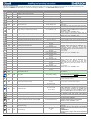
LABEL
VALUE
DESCRIPTION
RANGE
AMt
10
rAL
tEr
Probe for room temperature alarm.
ALC
rE
Room temperature alarm configuration: relative to
set point or absolute.
ALU
15.0
High room temperature alarm setting.
ALL
15.0
Low room temperature alarm setting.
[0.0°C to 50.0°C] or
[-55.0°C to ALU]
AHY
1.0
Differential for room temperature alarm.
[0.1°C to 25.5°C]
[1°F to 45°F]
ALd
15
Room Temperature alarm delay.
dLU
50.0
dLL
-50.0
dAH
1.0
Differential for temperature alarm (defrost probe).
ddA
15
Temperature alarm delay (defrost probe).
FLU
50.0
FLL
-50.0
FAH
1.0
Differential for temperature alarm (fan probe).
FAd
15
Temperature alarm delay (fan probe).
0 to 255min
dAo
1.3
Delay of temperature alarm at start-up.
0.0 to 24h00min (144)
EdA
20
Alarm delay at the end of defrost.
0 to 255min
dot
20
Temperature alarm exclusion after door open.
0 to 255min
Sti
nU
Stop regulation interval.
Time with fan at maximum speed or ON time for
relay on Anti-sweat regulation.
[10 to 60s] or
[10 to 60min]
NOTES
trA = AC: Anti-sweat heaters cycle period;
trA = rEG: Time with fan at maximum speed.
During this time the fan works at maximum speed. If
intended for fan, the basetime is on seconds, for antisweat regulation the basetime is on minutes.
ALARM
nP; P1; P2; P3; P4; P6; tEr
rE; Ab
[0.0°C to 50.0°C] or
[ALL to 150.0°]
0 to 255min
High temperature alarm setting (defrost probe).
Always absolute.
Low temperature alarm setting (defrost probe).
Always absolute.
[dLL to 150.0°C]
[dLL to 302°F]
[-55.0°C to dLU]
[-67°F to dLU]
[0.1°C to 25.5°C]
[1°F to 45°F]
0 to 255min
High temperature alarm setting (fan probe). Always
absolute.
Low temperature alarm setting (fan probe) Always
absolute.
Std
5
Stop duration.
tbA
Y
Silencing alarm relay by pressing a key.
[FLL to 150.0°C]
[FLL to 302°F
[-55.0°C to FLU]
[-67°F to FLU]
[0.1°C to 25.5°C]
[1°F to 45°F]
0.0 to 24h00min (144)
nU
1 to 255min
n; Y
It selects the probe used to signal alarm temperature.
rE = High and Low alarms related to set-point;
Ab = High and low alarms related to the absolute
temperature.
ALC = rE:
[32°F to 90°F];
ALC = Ab: [ALL to 150°C] or [ALL to 302°F].
When this temperature is reached and after the ALd
delay time is expired, the HA alarm will be enabled.
ALC = rE:
ALC = Ab: [-55.0°C to ALU] or [-67°F to ALU].
After this temperature is reached and the ALd delay
time is expired, the LA alarm will be enabled.
Threshold recovery after a temperature alarm.
Time interval between the detection of an alarm
condition and the corresponding alarm signaling.
After this temperature is reached and the ddA delay
time is expired, the HAd alarm will be enabled.
After this temperature is reached and the ddA delay
time is expired, the LAd alarm will be enabled.
Threshold recovery after a temperature alarm.
Time interval between the detection of an alarm
condition and the corresponding alarm signaling.
After this temperature is reached and the FAd delay
time is expired, the HAF alarm will be enabled.
When this temperature is reached and after the FAd
delay time is expired, the LAF alarm will be enabled.
Threshold recovery after a temperature alarm.
Time interval between the detection of an alarm
condition and the corresponding alarm signaling.
After powering on the instrument: time interval between
the detection of the temperature alarm condition and
the alarm signaling. Format: hours.10min, resolution:
10min.
At the end of the defrost cycle: time interval between
the detection of the temperature alarm condition and
the alarm signaling.
After regulating continuously for Sti time, the valve
closes for Std time in order to prevent ice creation.
Format: hours.10min, resolution: 10min.
It defines stop regulation time after Sti. During this
interval, the display shows StP message.
-
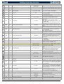
OUTPUT CONFIGURATION:
nU; CPr; dEF;
FAn; ALr; LiG;
AUS; db; onF; AC
OA1
CPr
Relay on terminals 9-10 configuration
CoM
CUr
Modulating output configuration.
CUr; tEn
AOP
CL
Alarm relay polarity.
OP; CL
iAU
n
Auxiliary output independent from ON/OFF state.
n; Y
nU = not used; CPr = compressor / valve; dEF = defrost;
FAn = Fan; ALr = Alarm; LiG = Light; AUS = auxiliary;
db = heater for neutral zone (not available with CrE = Y);
onF = ON/OFF; AC = anti-sweet.; E3r: solenoid valve for EX3 or for
mechanical solenoid valve
Cur = 4 to 20mA current output;
tEn = 0 to 10V voltage output.
CL = normally closed;
OP = normally opened.
n = if the instrument is switched off also the auxiliary
output is switched off;
Y = the auxiliary output state is unrelated to the
ON/OFF device status.
DIGITAL INPUTS
i1P
CL
Digital input 1 polarity.
i1F
dor
Digital input 1 configuration.
d1d
15
Digital input 1 activation delay.
1592023110 XM668D GB r2.6 03.04.2015
OP; CL
EAL; bAL; PAL;
dor; dEF; AUS;
LiG; OnF; Htr;
FHU; ES; HdY
0 to 255min
XM668D
CL = the digital input is activated by closing the contact;
OP = the digital input is activated by opening the
contact.
EAL = external alarm; bAL = serious external alarm;
PAL = pressure switch activation; dor = door open;
dEF = defrost activation; AUS = auxiliary activation;
LiG = light activation; OnF = switch on/off the
instrument;
Htr = change type of action; FHU = not used;
ES = activate energy saving; HdY = activate holiday
function.
When [i1F = PAL]: time interval to calculate the
number of the pressure switch activation.
When [i1F = EAL or bAL] (external alarms): d1d
parameter defines the time delay between the detection
and the successive signaling of the alarm.
When [i1F = dor]: this is the delay to activate door
open alarm.
13/15