1
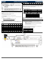
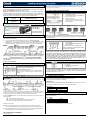
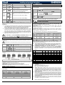
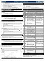
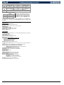
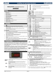
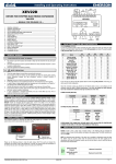
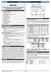
6.5 ABSOLUTE MAXIMUM POWER XM668D is able to drive a wide range of stepper valves, on the following table are indicated the maximum values of current that the actuator can supply to the stepper wiring. The TF20D Dixell transformer has to be used. dPP is the value read by the pressure gauge; dP6 is the value read by the temperature probe, temperature of the gas on the outlet section of the evaporator; SH is the value of the superheat. The nA or Err messages mean that the superheat has no sense in that moment and its value is not available. 6.10 HOW TO CONNECT MONITORING SYSTEM VALVE TYPE NOTE: the electrical power absorption of the valve can be unrelated to refrigeration power that valve has. Before using the actuator, please read the technical manual of the valve supplied by the manufacturer and check the maximum current used to drive the valve in order to verify that they are lower than those indicated below. BIPOLAR VALVES (4 wires) Maximum Current 0.9A UNIPOLAR VALVES (5-6 wires) Maximum Current 0.33A 1) 2) 3) 4) Terminals [36] [-] and [37] [+]. Use shielded twisted cable. For example Belden® 8762 o 8772 or cat 5 cables. Maximum distance 1Km. Don’t connect the shield to the earth or to GND terminals of the device, avoid accidental contacts by using insulating tape. 6.6 KEYBOARD DISPLAY CX660 Only one device for each LAN has to be connected to the RS485 connection. Polarity: Terminal [34] [-] Terminal [35] [+] Use shielded cable in case of long distance. The XM668D board can operate also without keyboard. 6.7 LAN CONNECTION Follow next steps to create a LAN connection, which is a necessary condition to perform synchronized defrost (also called master-slave functioning): 1) 2) The Adr parameter is the number to identify each electronic board. Address duplication is not permitted, in this case the synchronized defrost and the communication with monitoring system is not guaranteed (the Adr is also the ModBUS address). 6.11 DIGITAL INPUTS connect a shielded cable between terminals [38] [-] and [39] [+] for a maximum of 8 sections; the Adr parameter is the number to identify each electronic board. Address duplication is not permitted, in this case the synchronized defrost and the communication with monitoring system is not guaranteed (the Adr is also the ModBUS address). For example, a correct configuration is the following: 1) The terminals from [30] to [33] are all free of voltage; 2) Use shielded cable for distance higher than one meter; For each input, has to be configured: the polarity of activation, the function of the input and the delay of signaling. The parameters to perform this configuration are i1P, i1F, i1d respectively for polarity, functioning and delay. The i1P can be: cL = active when closed; oP = active when opened. The i1F parameter can be: EAL = external alarm, bAL = serious lock alarm, PAL = pressure switch alarm, dor = door switch, dEF = external defrost, AUS = auxiliary activation command, LiG = light activation, OnF = board On/OFF, FHU = don’t use this configuration, ES = day/night, HdY = don’t use this configuration. Then there is i1d parameter for delay of activation. For the others digital inputs there are a set of the same parameters: i2P, i2F, i2d, i3P, i3F, i3d. If the LAN is well connected, the green LED will be ON. If the green LED blinks then the connection is wrongly configured. 6.12 ANALOG OUTPUT The max distance allowed is 30m 6.8 SENSORS FOR SUPERHEAT CONTROL Temperature probe: Pb6 terminals [19] - [20] without any polarity. Selectable between 4 to 20mA and 0 to 10Vdc. Use CABCJ15 to perform the connections Select the kind of sensor with P6C parameter. It’s located near the terminal [39] on a 2-pin connector. It’s possible to use the output to control anti-sweat heaters through a chopped phase controller XRPW500 (500watt) or family XV...D or XV...K. Pressure transducer: Pb5 terminals: [21] = input of the signal; [22] = Power Supply for 4to20mA transducer; [20] = GND; [23] = +5Vdc power supply for ratiometric pressure transducer. 7. BATTERY BACK UP CONNECTION Select the configuration of the transducer with parameter P5C. 6.9 HOW TO USE ONLY ONE PRESSURE TRANSDUCER ON MULTIPLEXED APPLICATIONS 7.1 CONNECTION OF XEC SUPERCAP XEC Supercap is designed to be used with Dixell products (XM668D, XEV, IEV and others); compatibility with Dixell devices has to be verified in the user manual/technical sheet of the device. In case of dubt, please contact Dixell Service department. !!!!! IMPORTANT !!!!! XEC Supercap and XM668D must be powered by two different transformers; the failure of the observance of this rule may result in damage to the XEC Supercap and / or the connected XM668D. Wiring connection XM668D Terminal 61 (+) Terminal 62 (-) A working LAN connection is required (green LED lit on all XM668D boards of the same LAN). Connect and configure a pressure transducer only on one XM668D of the network. Afterwards, the value of pressure read by the unique transducer connected will be available to each device connected to the same LAN. By pressing UP ARROW button, the user will be able to enter a fast selection menu and to read the value of the following parameters: dPP = measured pressure (only on master device); dP5 = value of temperature obtained from pressure temperature conversion; rPP = pressure value read from remote location (only for slave devices). XEC Terminal 4 (12Vdc) Terminal 3 (gnd) 7.2 EMERSON ECP-024 CONNECTION The Emerson ECP-024 rechargeable accumulator can be connected to the XM668D to close the stepper valve in case of power interruption. Wiring connection XM668D Terminal 61 (+) Terminal 62 (-) ECP-024 Terminal + Terminal - About conditions of use and limitation please refer to the ECP-024 manuals. Examples of error messages: dPP = Err the local transducer read a wrong value, the pressure is out of the bounds of the pressure transducer or the P5C parameter is wrong. Check all these options and eventually change the transducer; rPF the remote pressure transducer is on error situation. Check the status of the onboard GREEN LED: if this LED is OFF the LAN is not working, otherwise check the remote transducer. LAST CHECKS ABOUT SUPERHEAT On the fast access menu: 1592023110 XM668D GB r2.6 03.04.2015 XM668D 3/15