1
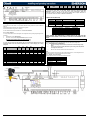
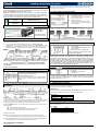
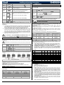
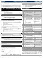
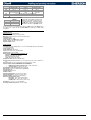
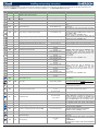
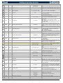
6.2 XM668D tEP Model 12 Emerson EX3 LSt uSt (steps*1 (steps*1 0) 0) 2 32 CPP (mA*10 ) 0 CHd (mA*10 ) 0 Sr tEu (bip/ (step/s) unip) 50 uP HSF (Half/f ull) HAF If you can see your valve on the table, please select the valve through tEP parameter. In this way, you can be sure of a right configuration. About the connection, please pay attention to the following table to have a quick reference on the connection mode for valves of different manufacturer 4 WIRES VALVES (BIPOLAR) Connection numbering 45 46 47 48 6.3 VALVE CONNECTIONS AND CONFIGURATION 6.3.1 Type of cables and max lenght To connect the valve to the controller, use only shielded cables with section greater than or equal to 0.823 mm² (AWG18). A twisted shielded cable with the the above specification is suggested. Don’t connect the shield to any ground, live it floating. !!!!! In any case, the unique and valid reference has to be considered the datasheet made by valve manufacturer. Dixell cannot be considered responsible in case of valve damaging due to wrong settings!!!!!! Model 0 1 2 3 4 5 6 7 8 9 10 11 Manual settings Danfoss ETS-25/50 Danfoss ETS-100 Danfoss ETS-250/400 Sporlan SEI .5 to 11 Sporlan SER 1.5 to 20 Sporlan SEI 30 Sporlan SER(I) G,J,K Sporlan SEI-50 Sporlan SEH(I)-100 Sporlan SEH(I)-175 Emerson EX4-EX5-EX6 LSt uSt (steps*1 (steps*1 0) 0) Par Par 7 262 10 353 11 381 0 159 0 159 0 319 0 250 0 638 0 638 0 638 5 75 CPP (mA*10 ) Par 10 10 10 16 12 16 12 16 16 16 50 CHd (mA*10 ) Par 10 10 10 5 5 5 5 5 5 5 10 DANFOSS ETS WHITE BLACK RED GREEN BLACK WHITE RED GREEN Connection numbering 45 46 47 48 49 – Common SPORLAN ORANGE RED YELLOW BLACK GRAY SAGINOMIYA ORANGE RED YELLOW BLACK GRAY AFTER MAKING THE CONNECTION, PLEASE SWITCH OFF AND ON THE CONTROLLER IN ORDER TO BE SURE OF THE RIGHT POSITIONING OF THE VALVE. 6.4 WIRING CONNECTION OF EMERSON EX3 VALVE CHECK THE FOLLOWING TABLE FOR A RIGHT SETTING tEP SPORLAN SEI-SEH-SER 5-6 WIRES VALVES (UNIPOLAR) The max distance between an XM controller and a valve must not exceed 10 m. 6.3.2 Valve selection To avoid possible problems, before connecting the valve configure the driver by making the right changes on the parameters. a. Select the kind of motor (tEU parameter) b. Check if the valve is present in tEP parameter table reported here below. ALCO EX4/5/6/7/8 BLUE BROWN BLACK WHITE Sr tEu (bip/ (step/s) unip) Par 300 300 300 200 200 200 200 200 200 200 350 Par bP bP bP bP bP bP bP bP bP bP bP HSF (Half/f ull) Par FUL FUL FUL FUL FUL FUL FUL FUL FUL FUL FUL XM668D AND EX3 CONNECTION The EX3 valve integrates a solenoid valve with posisitive shut off on the top and a stepper valve. 6.4.1 SOLENOID VALVE CONNECTION a. Verify the coil voltage of solenoid valve, and make sure it’s the same voltage of relay output. b. Set oA3 = E3r (solenoid coil of EX3). Be carefull any other setting of the oA3 parameter can damage the solenoid valve c. With oA3 = E3r connect the solenoid valve to the terminals 9-10. NOTE The solenoid coil will be energized every time the regulation temperature is on, and de-energised when the temperature regulation is off, and during the stand by of the controller. 6.4.2 Stepper valve connection The EX3 unipolar valve has to be connected to the following terminals. XM668D EX3 Terminal 49 Terminal 48 Terminal 47 Terminal 46 Terminal 45 Grey wire Blue wire Black wire Brown wire White wire E.I. Connection of EX3 with oA3 = E3r and 230V coil of solenoid valve (EX3-C230) 1592023110 XM668D GB r2.6 03.04.2015 XM678D 2/15