1
IMPOSA VELO IV installation manual
6.
Cabling an IMPOSA VELO IV display
This chapter covers the system cabling and ground protection of an IMPOSA VELO IV display.
Overview
Cabling between Units
System cabling
Grounding
Pixel limitations
Necessary tools
6mm Cross head screw driver
6mm hexagonal key
6.1
Cabling between Units
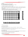
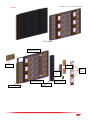
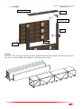
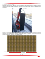
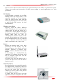
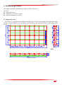
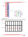
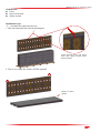
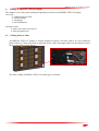
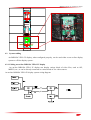
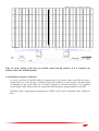
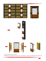
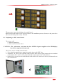
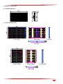
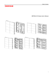
An IMPOSA VELO IV display is usually shipped in blocks. All inner cables are well connected
before delivery. Client only needs to plug the power cables and signal cables on the bottom of each
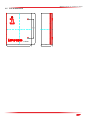
block, as the figure below shows.
signal cables
power cables
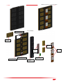
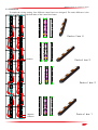
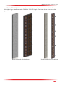
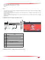
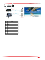
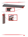
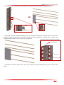
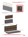
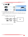
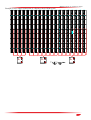
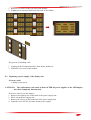
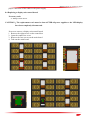
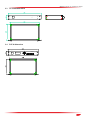
The inner cabling of IMPOSA VELO IV cabinet goes as follows:
File NO. WI/CZ-PM-M0004 Ver1.1
32