1
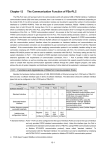
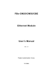
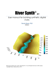
VLM4997 User's Manual This manual describes the input for John Lamar's vortex lattice program. The program resides on trident.aoe.vt.edu. In order to run the code, the user must have an account on trident. This can be obtained from the Design Lab Administrator. The user should then check to make sure that /usr/local/bin is in the default path. This can be checked by typing: 'printenv PATH'. If this directory is not in the default path, it can be added by editing the '.login' file in the user's home directory. Before running the code, the user should create a working directory within his home directory for the data files. After changing into this new directory, the user should copy the default input file. This is done by typing: 'cp /aero/vlm4997/VLM.DAT .' Note that the command ends with a space and then a period. This tells cp to place a copy of the file in the current directory with the same name. Now the user can run the code by simply typing: 'vlm' The code will automatically use the data file called 'VLM.DAT' in the current directory. Therefore to run a different case, the user must either modify this input file, or copy another input file to the name 'VLM.DAT'. The output goes to file named PRN. The theory is described in the following references, and the user’s manual provided here is basically the instructions from reference 4, with minor corrections and clarifications. References: 1. Margason, R.J., and Lamar, J.E., “Vortex-Lattice FORTRAN Program for Estimating Subsonic Aerodynamic Characteristics of Complex PLanforms,” NASA TN D-6142, Feb., 1971. 2. Lamar, J.E., and Gloss, B. B. “Subsonic Aerodynamic Characteristics of Interacting Lifting Surfaces with Separated Flow around Sharp Edges Predicted by a Vortex-Lattice Method,” NASA TN D-7921, Sept., 1975. 3. Lamar, J.E., and Frink, N.T., “Experimental and Analytic Study of the Longitudinal Aerodynamic Characteristics of Analytically and Empirically Designed Strake-Wing Configurations at Subcritical Speeds, “ NASA TP-1803, June 1981. 4. Lamar, J.E., and Herbert, H.E., “Production Version of the Extended NASA-Langley Vortex Lattice FORTRAN Computer Code,” - Volume I - User’s Guide, NASA TM 83303, April 1982. VLM 4997 User’s Guide - (from reference 4) 1. ABSTRACT/SUMMARY This document summarizes the latest production version, Mark 4.997, of the NASA-Langley Vortex Lattice Computer Program. All viable subcritical aerodynamic features of previous versions have been retained. This version extends the previously documented program capabilities to four planforms, 400 panels, and enables the user to obtain vortex-flow aerodynamics on cambered planforms, flow field properties off the configuration in attached flow, and planform longitudinal load distributions. 1 Wednesday, November 20, 1996 2. INTRODUCTION The NASA - Langley Vortex Lattice FORTRAN Program (VLM) is designed to estimate the subsonic aerodynamic characteristics of up to four complex planforms. The concepts embodied in this program are mostly detailed in references 1 and 2; this document is intended to serve as an update to these references and include the additional concept of reference 3 for users of this program. 3. MODELING THE CONFIGURATION The configuration can be modeled with up to four planforms, all of which must extend to the plane of symmetry (Y = 0.0). The fuselage is represented by its planar projection; experience to date indicates that this produces acceptable global forces and moments for most wing-bodytail configurations. Winglets can be modeled, but the dihedral angle must be less than 90.0 degrees and greater than -90.0 degrees. Both upper (positive dihedral) and lower (negative dihedral) winglets can be accounted for in this code. The program uses as its solution surface the chord plane which may be inclined due to dihedral. Moreover, the only out of "X-Y plane" displacement specifically allowed for is dihedral. Local camber and twist is assumed to be small and can be represented by its slope projection to the local solution surface. The wind and body axes are assumed to be coincidental in the code. 4 RUNNING THE PROGRAM 4.1 INPUT DATA SETUP The very first card of input is the Title card, and the user can have up to 80 characters of free field information on it about the data being run. This is only used by the program as a header for output. Note that there is only one title card per input deck. The actual input data to VLM is organized into two distinct groups - group 1 defines the reference planform(s), and group 2 defines the details for the particular solution. An example input follows the description of the input and output. The individual details of the items in the deck layout are given in the following sections. 4.2 GROUP 1 DATA This group of data defines the planform(s) projected into the X-Y plane, with all the coordinates being given for the left half of the configuration (negative y values!). The axis system is shown in Figure 1. The Y = 0 intercept coincides with the plane of symmetry and is positive to the right of this plane. The X = 0 intercept may be taken to occur anywhere along the symmetry plane of the configuration; X is positive pointing into the wind. 2 Wednesday, November 20, 1996 X Note: X opposite standard aerodynamic convention Y 1 2 Planform 1 3 4 5 6 1 2 3 4 Planform 2 5 7 6 Figure 1. Definition of axis system for VLM4997. All cards use the 8F10.6 format for the group 1 data. The fields in this group are as follows: 1. (Cols. 1-10) PLAN - Number of planforms for this configuration; PLAN can assume values of 1.0, 2.0, 3.0, or 4.0. 2. (Cols.11-20) TOTAL - Number of sets of group 2 data specified for this configuration. The maximum number of data sets is limited by the computation time (specified by the user) and the print limit (50000 lines). 3. (Cols.21-30) CREF - Reference chord of the configuration. This chord is used only to nondimensionalize the pitching-moment terms and must be greater than zero. 4. (Cols.31-40) SREF - Reference area; this is used only to nondimensionalize the computed output data such as lift and pitching moment and must always be greater than zero. 5. (Cols.41-50) XLOCTN - Pitching moment reference point location relative to coordinate origin along the X axis. 6. (Cols.51-60) CTILDA - Characteristic chord in the augmented vortex lift computations (see reference 3.) 7. (Cols.61-70) XTILDA - X location of the centroid of augmented vortex lift. 8. (Cols.71-80) DISTALE - Distance along the leading edge where the vortex flow is developed that leads to the augmented vortex lift. 3 Wednesday, November 20, 1996 The data required to define the planform(s) is provided in the next set of group 1 cards as follows: 1. (Cols.1-10) AAN - Number of line segments used to define the left half of the planform (does not include the innermost streamwise). A maximum of 24 line segments may be used per planform, and each planform must extend to the plane of symmetry. 2. (Cols.11-20) XS - X location of the pivot; use 0.0 for a fixed planform. 3. (Cols.21-30) YS - Y location of the pivot; use 0.0 for a fixed planform. 4. (Cols.31-40) RTCDHT - Vertical distance of the particular planform being read in with respect to the reference planform root chord height; use 0. for the reference planform. 5. (Cols.41-50) STLOIND - Streamwise load indicator; Set this value to 0. if the loading along the entire outer streamwise edge or at the outermost breakpoint of this planform is to be 0.0. If the loading is to be non-zero along the entire edge, or at the outermost breakpoint, set this indicator to 1.0. The rest of this set of data describes the breakpoints used to define the AAN line segments on this planform. There are (AAN+1) breakpoints and all data subsequently described are required on all except the last card of this set; the last card uses only the first two variables in the following list: 1. (Cols.1-10) XREG(I) - X location of the ith breakpoint. The first breakpoint is located at the most inboard location of the leading edge for the left-hand side of this planform. The other breakpoints are numbered around the planform perimeter in increasing order for each intersection of lines in a counterclockwise direction. 2. (Cols.11-20) YREG(I) - Y location of the ith breakpoint. Once the absolute value of Y starts to decrease, it cannot be increased. 3. (Cols.21-30) DIH(I) - Dihedral angle (degrees) in the Y-Z plane of the line from breakpoint of i to i+1, positive upward. Note that along a streamwise line, the dihedral angle is not defined, so use 0.0. for these lines. Note the sign of the dihedral angle is the same along the leading and trailing edges. 4. (Cols.31-40) AMCD - The move code; this number indicates whether the line s is on the movable panel of a variable-sweep wing. Use 1.0 for a fixed line (defaults to 1.0 if not set), or 2.0 for a movable line. Good results require that a few common rules of thumb be used in selecting the planform break points. The number of line segments should be minimized. Breakpoints should line up streamwise on front and rear portions of each planform, and should line up between planforms. Streamwise tips should be used, and small spanwise distances should be avoided by making edges streamwise if they are actually very highly swept. 4 Wednesday, November 20, 1996 4.3 GROUP 2 DATA There are eight sections of group 2 data. Each section may be required or optional, depending on the previous input, and each may have one or more input cards (lines of input). Each section is described individually. 4.3.1 Section one data is always required. [1 Card - Format (A20,8F5.2, 8F2.0, 4I1)] 1. (Cols.1-20) CONFIG - An arbitrary configuration designation of up to 20 alphanumeric characters. 2. (Cols.21-25) SCW - The number of chordwise horseshoe vortices to be used at a spanwise station for each planform. The maximum value for this variable is 20. If varying values of chordwise horseshoe vorticies are desired due to either multiple planforms or large discontinuities in chord across the span, the user can input a value of 0. that will cause the program to expect user-supplied data at this point in the input stream. The data are in the form of a table that contains the number of chordwise horseshoe vortices from the tip to root, and is called TBLSCW(I). This SCW=0. option can only be used for planforms without dihedral and for coplanar configurations. SCW must be greater than, or equal to, 2. for cambered wing vortex flow aerodynamic and KV, se solutions. 3. (Cols.26-30) VIC - The nominal number of spanwise stations at which chordwise horseshoe vortices will be located. This variable must not cause more than 100 spanwise stations to be used by the program in describing the left half of the configuration. In addition, the product of the stations spanwise and SCW cannot exceed 400. If SCW is 0., then the sum of the value sin TBLSCW(I) cannot exceed 400. The use of variable VIC is discussed in references 1 and 2. VIC should always be greater than, or equal to, 10. so that the near-field drag or vortex flow forces on cambered configurations can be properly computed. 4. (Cols.31-35) MACH - Mach number; use a value other than 0.0 only if the PrandtlGlauert compressibility correction factor is to be applied. The value used should be less than that of the critical Mach number. 5. (Cols.36-40) CLDES - Desired lift coefficient, CL,d. The number specified here is used to obtain the span load distribution at a particular lift coefficient. If the drag polar is required over a CL range from -0.1 to 1.0, use CLDES = 11.; if the vortex flow aerodynamic characteristics are required on a cambered and/or twisted configuration, use CLDES=100. (see page 21). If the vortex flow characteristics are required for a specific set of angles of attack, use 101. 6. (Cols.41-45) SA(1) - Variable sweep angle for the first planform. Specify the leading edge sweep-angle (in degrees) for the first movable line adjacent to the fixed portion of the planform. For a fixed planform, this quantity may be omitted. 7. (Cols.46-40) SA(2) - same, for the second planform. 5 Wednesday, November 20, 1996 8. (Cols.51-55) SA(3) - same, for the third planform. 9. (Cols.56-60) SA(4) - same, for the fourth planform. 10. (Cols. 61-62) TWIST(1) - Twist code for the first planform. If this planform has no twist and/or camber, use a value of 0.; otherwise, specify a value of 1. or 2. Use 1. if the data in section five is in radians; use a 2. if the data is in degrees. 11. (Cols.63-64) TWIST(2) - same, for the second planform. 12. (Cols.65-66) TWIST(3) - same, for the third planform. 13. (Cols.67-68) TWIST(4) - same, for the fourth planform. 14. (Cols.69-70) PTEST - Clp indicator; if the damping-in-roll parameter is desired, use 1.0 for this quantity. Except for the Delta Cp and Clp, all other aerodynamic data will be omitted. Use a 0. if Clp is not required. 15. (Cols.71-72) QTEST - CLq and Cmq indicator; if these stability derivatives are desired, use a 1.0 for this quantity. Except for Delta Cp, Clq, and Cmq, all other aerodynamic data will be omitted. It should be noted that both PTEST and QTEST cannot be set equal to 1. simultaneously for a particular configuration. Use 0. if Clq and Cmq are not required. 16. (Cols.73-74) ATPCOD - Set to 0., it will cause only linear aerodynamic results to be printed out. Set to 1., this will cause the program to print out the contributions to the lift, drag and moment from the separated flow around the leading/side edges. Set to 2., it will provide the local flow field velocities away from the configuration, and set to 3., it will provide the attached flow longitudinal load distribution (see page 19). 17. (Cols.75-76) REPORT - Vortex flow report option. For sectional, planform, and overall characteristics, use a 0. For planform and overall characteristics, use a 1. For overall characteristics only, use a 2. The value used here will not affect the information written to the SIF file "SIF1". 18. (Col.77) LERAD(1) - Leading edge radius indicator for the first planform. If this planform has no leading edge radius, use a 0. Otherwise, specify the number of (Y location, LE radius) pairs available for interpolation across this planform (see section 4.3.6). At least 2, but no more than 8 pairs may be specified. These pairs need not be in any particular order. 19. (Col.78) LERAD(2) - same, for the second planform. 20. (Col.79) LERAD(3) - same, for the third planform. 21. (Col.80) LERAD(4) - same, for the fourth planform. 6 Wednesday, November 20, 1996 4.3.2 Section two data is required when ATPCOD=1. (see section 4.3.1). This section sets up the limits of integration used in the computations of the wing leading-edge and side-edge suction values. If the configuration does not have side edges, use zeroes for the values of XL(I) and XT(I) on the second card. [2 Cards - Format (8F10.6/8F10.6)] Card 1: 1. (Cols.1-10) YINNER(1) - Represents the Y inner for the first planform. 2. (Cols.11-20) YOUTER(1) - Represents the Y outer for the first planform. 3. (Cols.21-30,31-40) YINNER(2), YOUTER(2) - same, for the second planform. 4. (Cols.41-50,51-60) YINNER(3), YOUTER(3) - same, for the third planform. 5. (Cols.61-70,71-80) YINNER(4), YOUTER(4) - same, for the fourth planform. Card 2: 1. (Cols.1-10) XL(1) - The leading edge tip X-coordinate for the first planform. 2. (Cols.11-20) XT(1) - The trailing edge tip X-coordinate for the first planform. 3. (Cols.21-30,31-40) XL(2), XT(2) - same, for the second planform. 4. (Cols.41-50,51-60) XL(3), XT(3) - same, for the third planform. 5. (Cols.61-70,71-80) XL(4), XT(4) - same, for the fourth planform. 4.3.3 Section three data is required when CLDES-101. (see section 4.3.1). This section allows theuser to choose the particular angles of attack to be used in the vortex flow analysis computations. [1 card - Format (3F10.6) ] 1. (Cols.1-10) BEGAA - Beginning angle of attack (in degrees). This value must be greater than -90., but less than +90. 2. (Cols.11-20) STEPAA - Step angle of attack (in degrees). This value must be greater than -180., less than +180., but not equal to 0. 3. (Cols.21-30) NUMAA - Number of angles of attack. This value must be at least 1., but no more than 26. In addition, the resulting ending in angle of attack, ENDAA = BEGAA + ((NUMAA 1)*STEPAA), must be greater than -90., but less than +90. 7 Wednesday, November 20, 1996 4.3.4 Section four data is required when SCW=0. (see section 4.3.1). This section determines the number of span stations for each planform, and the number of chordwise control points along each span station. [Multiple card sets per planform - Format (F5.1,n(/16F5.1))] Card 1: (Cols.1-5) STA - Number of spanwise stations of horseshoe vortices on the left half of the planform. This variable sets the number of TBLSCW values read in for that planform. Cards 2-n: (Cols. 1-5,6-10,etc) TBLSCW(I) - Number of horseshoe vortices at each spanwise station beginning at the station nearest the tip of the planform and proceeding toward the station nearest the root. These sets of STA and TBLSCW(I) cards are repeated for each planform. The sum of all the STA values cannot exceed 100. 4.3.5 Section five data is required for any planform having a nonzero value for TWIST(I) (see section 4.3.1). This section determines the mean camber line slopes or angles of attack across the planform. [Multiple cards per planform - Format (8F10.6,n(8F10.6))] (Cols.1-10,11-20,etc.) ALP - Local streamwise angles of attack, eg. camber flap deflection, in radians if TWIST = 1., or in degrees if TWIST = 2. These are the values at the control point for each horseshoe vortex on the planform when the innermost streamwise edge of the reference planform has an angle of attack of 0. degrees. The volume of this data will usually require several input cards. For the first value on the first card, use the local angle of attack for the horseshoe vortex nearest the first planform leading edge at the tip; for the second value, use the angle of attack for the horseshoe vortex immediately behind in the chordwise direction. Continue in the same manner for the rest of the horseshoe vortices at the tip. Begin a new card for the next inboard station and input the data in the same chordwise manner. Repeat for all successive inboard spanwise stations on that planform. For each planform with twist/camber, start the data on a new card and specify the data from the tip and proceed chordwise and then inboard, as detailed above. 4.3.6 Section six data is required for any planform having a nonzero value for LERAD(I) (see section 4.3.1). This section determines the distribution of leading edge radius across the planform. The parameter "LERAD" also specifies how many (Y location, LE radius) pairs are specified in this section. [ 2 Cards - Format (8F10.6/8F10.6) ] 8 Wednesday, November 20, 1996 Card 1: (Cols.1-10,11-20,etc) YLE - Y span locations of the leading edge radius values. Card 2: (Cols.1-10,11-20,etc.) RADLE - The corresponding leading edge radius values in the same dimensional units as previously used. 4.3.7 Section seven data is required when ATPCOD-2. (see section 4.3.1). and CLDES is not equal to 11., 100., or 101. (see section 4.3.1). This section sets up the field lines used in the flow field analysis. [TOTFL+1 Cards - Format (2F10.6,n(/8F10.6))] Card 1: 1. (Cols.1-10) TOTFL - Total number of field lines. This also controls the read of the field line data cards (maximum of 60). 2. (Cols.11-20) TOTFP - Total number of points along each field line. If omitted, a value of 75. is assumed. Cards 2-n: 4.3.8 1. (Cols.1-10) XDOWN - X location where the field line intersects the plane of symmetry (positive forward) 2. (Cols.11-20) SWEP - Sweep angle of field line in X-Y plane in degrees. (sweepback is positive nd -90. deg. <SWEP< 90. deg.) 3. (Cols.21-30) ZREF - Z height of the field line at the plane of symmetry. (positive down) 4. (Cols.31-40) DIHED - Dihedral angle of the field line in the Y-Z plane, in degrees (Standard convention is employed to determine positive values; -90. deg. <DIHED < 90. deg.) Section eight data is always required. VLM is able to create three SIF files, called "SIF1", "SIF2", and "SIF3". These files contain the significant information from three main sections of output: vortex flow aerodynamic results, linear aerodynamic results, and a description of the horseshoe vortices, respectively. [1 Card - Format (3F10.6) } 1. (Cols.1-10) SIF1 - First SIF file creation indictor. To create the SIF file containing the vortex flow aerodynamic results, use a 1. Otherwise, use a 0. (default). 9 Wednesday, November 20, 1996 2. (Cols.11-20) SIF2 - Second SIF file creation indicator. To create the SIF file containing the linear aerodynamic results, use a 1. Otherwise, use a 0. (default). 3. (Cols.21-30) SIF3 - Third SIF file creation indicator. To create the SIF file containing a description of the horseshoe vortices, use a 1. Otherwise, use a 0. (default) 5 OUTPUT DATA The printed results of this computer program appear in two parts: geometry data and aerodynamic data. 5.1 GEOMETRY DATA The geometry data are described in the order that they are found on the printout. 5.1.1 The first group of the data describes the basic configuration: it states the numbers of lines used to describe each planform, the root chord height, pivot position, and then lists the breakpoints, sweep and dihedral angles, and move codes. These data are basically a listing of input data except that the X coordinates are adjusted to the reference point location and the sweep angle is computed from the input. 5.1.2 The second group of data describes the particular configuration for which the aerodynamic data are being computed. Included are the configuration designation, sweep position, a listing of the breakpoints of the planform (X,Y, and Z), the sweep and dihedral angles, and the move codes. The data are listed primarily for variable-sweep wings to provide a definition of the planform where the outer panel sweep is different from that of the reference planform. This is followed by a "printer plot" of the approximate configuration. 5.1.3 The third group of data presents a detailed description of the horseshoe vortices used to represent the configuration. These data are listed in nine columns with each line describing one elemental panel of the configuration (see Figure 2) in the same order that the twist and/or camber angles of attack are to be provided. 10 Wednesday, November 20, 1996 X b/2 Y y xc/4 ψ x 3c/4 • Line of symmetry Control point 2s cosφ • 2s z φ Y Z Figure 2. Nomenclature used to describe the geometry of an elemntal panel. The following items of data are presented for each elemental panel: 1. X C/4 - X location of quarter-chord at the horseshoe vortex midspan. 2. X 3C/4 - X location of three-quarter-chord at the horseshoe vortex midspan. This is the X location of the control point. 3. Y - Y location of the horseshoe vortex midspan. 4. Z - Z location of the horseshoe vortex midspan. 5. S - Semiwidth of horseshoe vortex. 6. C/4 SWEEP ANGLE - Sweep angle of the quarter-chord of the elemental panel and horseshoe vortex. 7. DIHEDRAL ANGLE - Dihedral angle of elemental panel. 8. LOCAL ALPHA IN RADIANS - Local angle of attack in radians at control point (X @ 3C/4,Y,Z). 9. DELTA CP AT DESIRED CL - Delta Cp or Net Cp normal to the surface at dihedral for each elemental panel when the total lift is CL,d. 11 Wednesday, November 20, 1996 5.1.4 The fourth group of data presents the following geometric results: 1. REF.CHORD - Reference chord of the configuration. 2. C AVERAGE - Average chord, cav, true configuration area divided by true span. 3. TRUE AREA - True area computed from the configuration listed in second group of geometry data. 4. REFERENCE AREA - Reference area. 5. B/2 - Maximum semispan of all planforms listed in second group of geometry data. 6. REF. AR - Reference aspect ratio computed from the reference planform area and true span. 7. TRUE AR - True aspect ratio computed from the true planform area and true span. 8. MACH NUMBER - Mach number. 5.2 AERODYNAMIC DATA If PTEST = 1. or QTEST = 1. on the configuration card, then either Clp or CLq and Cmq are computed and printed, followed by program termination. Otherwise, the aerodynamic data are described by at least two groups of results. The first is always present, but the second depends on what is requested on the configuration card. The following items of the first group of data are given in the order that they are found on the printout. Note that CL ALPHA, CL(TWIST), CM/CL, CMO, CDI/CL**2 are based on the specified reference dimensions. Many of the items that follow are for the complete configuration. 5.2.1 1. DESIRED CL - Desired lift coefficient, CL, d, specified in Input Data for complete configuration. 2. COMPUTED ALPHA - Angle of attack at which the desired lift is developed: CL, d/(CL ALPHA) + ALPHA at CL=O. 3. CL(WB) - That portion of desired lift coefficient developed by the planform with the maximum span when multiple planforms are specified. When one planform is specified, this is the desired lift coefficient. (If two or more planforms have the same span, and this value is equal to the maximum, the planform used here is the latter one read in). 4. CDI AT CL(WB) - Induced drag coefficient for lift coefficient in the previous item. When two or more planforms are specified, this is the induced drag coefficient of only the planform with the maximum span. This result is based on the far-field solution. 12 Wednesday, November 20, 1996 5. CDI/(CL(WB)**2) - Induced drag parameter computed from the two previous items. 6. 1/(PI*AR REF) - Induced drag parameter for an elliptic load distribution based on reference aspect ratio. 7. CL ALPHA - Lift-curve slope per radian, and per degree. 8. CL(TWIST) - Lift coefficient due to twist and/or camber at zero angle of attack (CL,tc). 9. ALPHA AT CL=O - Angle of attack at zero lift in degrees; nonzero only when twist and/or camber is specified. 10. Y CP - Spanwise distance in fraction of semispan from root chord to center of pressure on the left wing panel. 11. CM/CL - Longitudinal stability parameter based on a moment center about the reference point. 12. CMO - Pitching-moment coefficient at CL=O. 13. CL ALPHA, CL(TWIST), ALPHA, and Y CP are also printed for each planform. For each spanwise station, the following data are presented; from the left tip towards the root: 1. 2Y/B - Location of midpoint of each spanwise station in fraction of wing semispan. The next two columns of data describe the additional (or angle of attack) wing loading at a lift coefficient of 1. (based on the total lift achieved and the true configuration area). The third column is the chord ratio result, and the other columns detail specific kinds of span loadings and local centers of pressure for the configuration. The preceeding is done on a planform basis. 1. SL COEF - span-load coefficient, clc/CLcav. 2. CL RATIO - Ratio of local lift to total lift, cl/CL. 3. C RATIO - Ratio of local chord to averge chord, c/cav. 4. LOAD DUE TO TWIST - Distribution of Span-load coefficient due to twist and camber at 0. degrees angle of attack for the configuration. 5. ADD. LOAD AT CL= - Distribution of additional span-load coefficient at CL,tc. 6. BASIC LOAD AT CL=0 - Basic span-load-coefficient distribution at zero lift coefficient. These data are the difference of the previous two columns of data. 7. SPAN LOAD AT DESIRED CL - Distribution of the combination of the basic span-load and additional span-load coefficients at the desired CL. 13 Wednesday, November 20, 1996 8. AT CL DES - X LOCATION OF LOCAL CENT PR - The X location of the local center of pressure for the resulting span load at CL,d as a function of 2Y/b. 5.2.2 The other options available as group two aerodynamic data are accessed based on the values of CLDES and ATPCOD. For instance, with CLDES=11., and ATPCOD=0.0, the program will produce a drag polar, CDI at CL(WB) versus CL(WB), based on the linear aerodynamics in the middle of the first part of group one aerodynamic data. This, and other combinations, are given in the table below, along with their purposes: COMBINATION i ii iii iv v vi vii viii ix x xi xii CLDES 101.,100.>CL,d>0. 11. 101.100. 101.,100.>CL,d>0. 11. 101.,100 101.,100.>CL,d>0. 11. 101.,100 101.,100.>CL,d>0. 11. 101.,100. ATPCOD 0. 0. 0. 1. 1. 1. 2. 2. 2. 3. 3. 3. PURPOSE Determine linear aerodynamics Linear aerodynamic drag polar not valid Planar-wing vortex-flow aerodynamics not valid Cambered-wing vortex-flow aerodynamics Determine flow field off wing not valid not valid Determine longitudinal load distribution not valid not valid For combinations i,iv, and x, the induced drag, leading-edge thrust, and suction coefficient characteristics at each spanwise station are computed from a near-field solution for the total loading at CL,d and presented. 1. L.E. SWEEP ANGLE - Leading-edge sweep angle in degrees. 2. CDII C/2B - Nondimensional section induced-drag-coefficient term. 3. CT C/2B - Nondimensional section leading-edge thrust-coefficient term. 4. CS C/2B - Nondimensional section leading-edge suction-coefficient term. 5. CDII/CL**2 - Total drag coefficient over (CL,d)**2. 6. CT - Total leading-edge thrust coefficient. 7. CS - Total leading-edge suction coefficient. This completes the printout for combination i; however, for combination iv additional printout is produced. In particular, Kp and Kv values, and respective centroids in both chordwise and spanwise directions, and the associated limits of integration for the leading- edge and side-edge values of Kv. (The item entitled "Sum of the positive side edge contributions" which appears 14 Wednesday, November 20, 1996 here on the printout is indicative of the contribution to the side-edge forces for that particular planform which were oppositely-signed to those that contributed in a manner to increase Kv,se. The value of Kv,se does contain these positive contributions provided the sweep angle is positive. They should not be, and therefore are not added in for the planform with a swept forward leading edge). Furthermore, aerodynamic performance values for each planform and for the entire configuration will be listed over an angle of attack range by the use of the Polhamus Suction Analogy. The headings are expalined below: KP KVLE KV SE ALPHA CN CLP CLVLE CLVSE CMP CMVLE CMVSE CM CD CL**2/(PI*AR) Kp Kv,le Kv,se α CN,tot CL,p CL,vle Kv,se |sinα| |sinα| cos α pitching-moment coefficient due to CL,p pitching-moment coefficient due to CL,vle pitching-moment coefficient due to CL,vse total pitching moment CL,tot x tanα (CL,tot)2 /(Pi*(Aspect Ratio)) The additional printout associated with combination x, which determines the longitudinal load distribution, is as follows: (see figure 4 for definition of the nomenclature) 1. X - The X location at which the spanwise integration of Delta Cp or Net Cp is to occur. 2. Y - The Y value at which Delta Cp or Net Cp is interpolated. 3. INTERPOLATED DELTA CP - The values of Delta Cp interpolated from the chordwise arrangement to that of a spanwise one. 4. BL(X) - Local span. (b1(x)) 5. CNL 2 yin b1 ( x ) CNL = 2y 2b1 ( x) ⌠ ∆Cp d b ⌡ b1( x ) 2 yle b1 ( x ) 6. CN FOR PLANFORM I CN(I) = L(b / 2) 1 CNL d(x / L) Sref ∫0 15 Wednesday, November 20, 1996 7. TOTAL CN - Total value of CN for the configuration where CN,tot = PLAN ∑ CN(I) I=1 X b/2 Y b (x) 1 2 L yle yin Figure 4. Nomenclature for longitudinal load distribution analysis. The vortex flow aerodynamics for cambered wings are determined when combination vi is specified, and is done from a solution in the body axis system of the leading-edge suction force acting on a deflected surface, over a range of angles of attack. Kv,le is not solved for in this solution, but its effect is calculated at each internally prescribed body axis angle of attack. Kv,se is solved for in the manner described in reference 2, and is tabulated. The headings on the printout are divided into attached flow and separated flow regions. Under the attached flow heading are the lift, drag, and pitching moment (CL, CD, CM) coefficients for both zero leading-edge suction and full leading-edge suction over the angle of attack range. These items include all the appropriate trigonometric terms. Regarding the vortex induced separated flow terms, some headings include the potential flow terms and some do not. Those which include the potential flow terms lead to "total" results whereas those which are isolated, such as side-edge or augmented vortex lift terms, do not lead to "total" values. The augmented vortex lift is described in Reference 3. Combination vii determines the flow field around the configuration in the attached flow. First the elemental panel circulation values, Gamma/U, associated with the basic load and the additional load at CL=1.0 are listed, followed by those associated with the total load and the additional load at the desired CL. This is followed by a heading which lists out the geometric data for the prescribed field line, along with the 16 Wednesday, November 20, 1996 desired CL and the required configuration angle of attack from linear attached-flow aerodynamics. Then from near the plane of symmetry to approximately three times the configuration semispan, the flow field properties are determined along that line. The X, Y, and Z coordinates of each field point and the associated normalized downwash (w/U), sidewash (v/U), and backwash (u/U) values are then listed. Note that the positive directions for these are downward for 2/U, out the right wing for v/U, and forward for u/U. These are followed by the induced downwash angles DWNWH, arctan(w/U) in degrees, Epsilon, d(Epsilon)/d(Alpha), the ratio of local dynamic pressure to free-stream dynamic pressure, Q(LOCAL/Q(INF), and the sidewash angle SIGMA, arctan(v/U) in degrees. Epsilon is a particular kind of downwash angle, given in degrees and defined by: Epsilon = Alpha - arctan[(sin(Alpha) - (w/U))/(cos(Alpha) - (u/U))] d(Epsilon)/d(Alpha) is just the differential of the above equation with respect to Alpha and may be useful in certain wing-tail-body problems. SAMPLE INPUT, - the B-2 as shown in Air International ANALYSIS OF THE B-2: AIR INTERNATIONAL GEOMETRY 1. 1. 1.0000 5040.1 0. 6.0 0.0 0.0 0.0 1.0 -59.47 -86.0 -67.9 -72.74 -48.26 -43.90 -63.24 -22.50 -56.82 -12.66 -65.46 0.0 BASIC LINEAR AERO 10. 18. 0.20 0.4 SAMPLE OUTPUT: The output is lengthy, and requires 133 columns. Run the sample case, and printout the output to obtain an output to study. 17 Wednesday, November 20, 1996