1
Engström Ventilator
Technical Reference Manual
Engström Ventilator
Datex-Ohmeda products have unit serial numbers with coded logic which indicates a product
group code, the year of manufacture, and a sequential unit number for identification. The serial
number can be in one of two formats.
AAA X 11111
AAA XX 111111AA
The X represents an alpha character
The XX represents a number indicating
indicating the year the product was
the year the product was manufactured;
manufactured; J = 2004, K = 2005, etc. 04 = 2004, 05 = 2005, etc.
I and O are not used.
Engström Ventilator, ComWheel, D-fend and EVair 03 are registered trademarks of
Datex-Ohmeda Inc.
Other brand names or product names used in this manual are trademarks or registered
trademarks of their respective holders.
10/04
1505-1018-000
Technical Reference Manual
Engström Ventilator
This document is not to be reproduced in any manner, nor are the contents to be disclosed to
anyone, without the express authorization of the product service department, Datex-Ohmeda,
Ohmeda Drive, PO Box 7550, Madison, Wisconsin, 53707.
©
1505-1018-000 10/04
2004 Datex-Ohmeda Inc.
i
Engström Ventilator
Important
The information contained in this Technical Reference manual pertains only to those models of
products which are marketed by Datex-Ohmeda as of the effective date of this manual or the
latest revision thereof. This Technical Reference manual was prepared for exclusive use by
Datex-Ohmeda service personnel in light of their training and experience as well as the
availability to them of parts, proper tools and test equipment. Consequently, Datex-Ohmeda
provides this Technical Reference manual to its customers purely as a business convenience
and for the customer's general information only without warranty of the results with respect to
any application of such information. Furthermore, because of the wide variety of circumstances
under which maintenance and repair activities may be performed and the unique nature of each
individual's own experience, capacity, and qualifications, the fact that customer has received
such information from Datex-Ohmeda does not imply in anyway that Datex-Ohmeda deems said
individual to be qualified to perform any such maintenance or repair service. Moreover, it should
not be assumed that every acceptable test and safety procedure or method, precaution, tool,
equipment or device is referred to within, or that abnormal or unusual circumstances, may not
warrant or suggest different or additional procedures or requirements.
This manual is subject to periodic review, update and revision. Customers are cautioned to
obtain and consult the latest revision before undertaking any service of the equipment.
Comments and suggestions on this manual are invited from our customers. Send your
comments and suggestions to the Manager of Technical Communications, Datex-Ohmeda,
Ohmeda Drive, PO Box 7550, Madison, Wisconsin 53707.
w CAUTION
Servicing of this product in accordance with this Technical Reference manual should never
be undertaken in the absence of proper tools, test equipment and the most recent
revision to this service manual which is clearly and thoroughly understood.
Technical Competence
The procedures described in this Technical Reference manual should be performed by trained
and authorized personnel only. Maintenance should only be undertaken by competent
individuals who have a general knowledge of and experience with devices of this nature. No
repairs should ever be undertaken or attempted by anyone not having such qualifications.
Datex-Ohmeda strongly recommends using only genuine replacement parts, manufactured or
sold by Datex-Ohmeda for all repair parts replacements.
Read completely through each step in every procedure before starting the procedure; any
exceptions may result in a failure to properly and safely complete the attempted procedure.
ii
10/04 1505-1018-000
Table of Contents
Important . . . . . . . . . . . . . . . . . . . . . . . . . . . . . . . . . . . . . . . . . . . . . . . . . . . . . . . . . . . . . . . . . . . . . .ii
Technical Competence . . . . . . . . . . . . . . . . . . . . . . . . . . . . . . . . . . . . . . . . . . . . . . . . . . . . . . . . . . .ii
1 Introduction
1.1 What this manual includes . . . . . . . . . . . . . . . . . . . . . . . . . . . . . . . . . . . . . . . . . . . . . . . . . .1-2
1.2 User’s Reference manuals . . . . . . . . . . . . . . . . . . . . . . . . . . . . . . . . . . . . . . . . . . . . . . . . . . .1-2
1.2 Conventions used . . . . . . . . . . . . . . . . . . . . . . . . . . . . . . . . . . . . . . . . . . . . . . . . . . . . . . . . . .1-2
1.3 What is an Engström Ventilator? . . . . . . . . . . . . . . . . . . . . . . . . . . . . . . . . . . . . . . . . . . . . . .1-3
1.4 Ventilator overview . . . . . . . . . . . . . . . . . . . . . . . . . . . . . . . . . . . . . . . . . . . . . . . . . . . . . . . . .1-4
1.5 Display controls and indicators . . . . . . . . . . . . . . . . . . . . . . . . . . . . . . . . . . . . . . . . . . . . . . .1-6
1.6 Ventilator display . . . . . . . . . . . . . . . . . . . . . . . . . . . . . . . . . . . . . . . . . . . . . . . . . . . . . . . . . . .1-7
1.6.1 Using menus . . . . . . . . . . . . . . . . . . . . . . . . . . . . . . . . . . . . . . . . . . . . . . . . . . . . . . . .1-9
1.7 Symbols used in the manual or on the equipment . . . . . . . . . . . . . . . . . . . . . . . . . . . . . 1-10
1505-1018-000 10/04
1
Engström Ventilator
2 Theory of Operation
2.1 Pneumatic Operation . . . . . . . . . . . . . . . . . . . . . . . . . . . . . . . . . . . . . . . . . . . . . . . . . . . . . . .2-2
2.1.1 Inspiratory circuit . . . . . . . . . . . . . . . . . . . . . . . . . . . . . . . . . . . . . . . . . . . . . . . . . . . .2-2
2.1.2 Expiratory circuit . . . . . . . . . . . . . . . . . . . . . . . . . . . . . . . . . . . . . . . . . . . . . . . . . . . . .2-7
2.1.3 Associated circuits . . . . . . . . . . . . . . . . . . . . . . . . . . . . . . . . . . . . . . . . . . . . . . . . . . .2-8
2.1.4 Electronic micropump nebulizer . . . . . . . . . . . . . . . . . . . . . . . . . . . . . . . . . . . . . . . .2-8
2.2 Electrical Operation . . . . . . . . . . . . . . . . . . . . . . . . . . . . . . . . . . . . . . . . . . . . . . . . . . . . . . . . .2-9
2.2.1 Display Unit (DU) . . . . . . . . . . . . . . . . . . . . . . . . . . . . . . . . . . . . . . . . . . . . . . . . . . . .2-9
2.2.2 Communication channels . . . . . . . . . . . . . . . . . . . . . . . . . . . . . . . . . . . . . . . . . . . 2-10
2.2.3 Ventilator Control Board - VCB . . . . . . . . . . . . . . . . . . . . . . . . . . . . . . . . . . . . . . . 2-12
2.2.4 Ventilator Monitoring Board - VMB . . . . . . . . . . . . . . . . . . . . . . . . . . . . . . . . . . . . 2-14
2.2.5 Power Management Board – PMB . . . . . . . . . . . . . . . . . . . . . . . . . . . . . . . . . . . . 2-16
2.2.6 Other Electronic Items . . . . . . . . . . . . . . . . . . . . . . . . . . . . . . . . . . . . . . . . . . . . . . 2-16
2.2.7 Motherboard (backplane) . . . . . . . . . . . . . . . . . . . . . . . . . . . . . . . . . . . . . . . . . . . 2-17
2.2.8 Monitoring Interface Board – Monitoring Module Bays . . . . . . . . . . . . . . . . . . . . 2-17
3 Checkout Procedure
3.1 Inspect the system . . . . . . . . . . . . . . . . . . . . . . . . . . . . . . . . . . . . . . . . . . . . . . . . . . . . . . . . .3-2
3.2 Automated Checkout . . . . . . . . . . . . . . . . . . . . . . . . . . . . . . . . . . . . . . . . . . . . . . . . . . . . . . .3-2
3.3 Backlight test . . . . . . . . . . . . . . . . . . . . . . . . . . . . . . . . . . . . . . . . . . . . . . . . . . . . . . . . . . . . . .3-3
3.4 Power failure test . . . . . . . . . . . . . . . . . . . . . . . . . . . . . . . . . . . . . . . . . . . . . . . . . . . . . . . . . . .3-3
3.5 Electrical safety tests . . . . . . . . . . . . . . . . . . . . . . . . . . . . . . . . . . . . . . . . . . . . . . . . . . . . . . .3-3
4 Installation and Service Menus
4.1 Service and Installation menu structure . . . . . . . . . . . . . . . . . . . . . . . . . . . . . . . . . . . . . . . .4-2
4.2 Install/Service Menu (Super User) . . . . . . . . . . . . . . . . . . . . . . . . . . . . . . . . . . . . . . . . . . . . .4-3
4.2.1 Defaults . . . . . . . . . . . . . . . . . . . . . . . . . . . . . . . . . . . . . . . . . . . . . . . . . . . . . . . . . . . .4-4
4.2.2 Factory Defaults . . . . . . . . . . . . . . . . . . . . . . . . . . . . . . . . . . . . . . . . . . . . . . . . . . . . .4-5
4.3 Calibration menu . . . . . . . . . . . . . . . . . . . . . . . . . . . . . . . . . . . . . . . . . . . . . . . . . . . . . . . . . . .4-6
4.4 Service menu . . . . . . . . . . . . . . . . . . . . . . . . . . . . . . . . . . . . . . . . . . . . . . . . . . . . . . . . . . . . . .4-7
4.4.1 Configuration . . . . . . . . . . . . . . . . . . . . . . . . . . . . . . . . . . . . . . . . . . . . . . . . . . . . . . .4-8
4.4.2 Copy Configuration . . . . . . . . . . . . . . . . . . . . . . . . . . . . . . . . . . . . . . . . . . . . . . . . . . .4-9
4.4.3 Service Log menu . . . . . . . . . . . . . . . . . . . . . . . . . . . . . . . . . . . . . . . . . . . . . . . . . . 4-10
4.4.4 Software/Hardware version menu . . . . . . . . . . . . . . . . . . . . . . . . . . . . . . . . . . . . 4-11
2
10/04 1505-1018-000
Table of Contents
5 Service Tests and Calibration
5.1 Calibration (super-user) . . . . . . . . . . . . . . . . . . . . . . . . . . . . . . . . . . . . . . . . . . . . . . . . . . . . .5-2
5.1.1 Calibration procedure . . . . . . . . . . . . . . . . . . . . . . . . . . . . . . . . . . . . . . . . . . . . . . . .5-3
5.2 Service level tests and calibration . . . . . . . . . . . . . . . . . . . . . . . . . . . . . . . . . . . . . . . . . . . . .5-4
5.2.1 Service application setup . . . . . . . . . . . . . . . . . . . . . . . . . . . . . . . . . . . . . . . . . . . . .5-4
5.2.2 Test setup . . . . . . . . . . . . . . . . . . . . . . . . . . . . . . . . . . . . . . . . . . . . . . . . . . . . . . . . . .5-4
5.2.3 Vent engine debris clean-out . . . . . . . . . . . . . . . . . . . . . . . . . . . . . . . . . . . . . . . . . . .5-5
5.2.4 Vent engine leak test (low pressure) . . . . . . . . . . . . . . . . . . . . . . . . . . . . . . . . . . . . .5-6
5.2.5 Vent engine leak test (high O2 pressure) . . . . . . . . . . . . . . . . . . . . . . . . . . . . . . . . .5-8
5.2.6 Vent engine leak test (high Air pressure) . . . . . . . . . . . . . . . . . . . . . . . . . . . . . . . .
5.2.7 Calibrate airway pressure transducer Zero and Span . . . . . . . . . . . . . . . . . . . . .
5.2.8 Verify operation of free- breathing valve . . . . . . . . . . . . . . . . . . . . . . . . . . . . . . . .
5.2.9 Verify operation of inspiratory effort valve . . . . . . . . . . . . . . . . . . . . . . . . . . . . . .
5.2.10 Verify operation of auxiliary pressure relief valve . . . . . . . . . . . . . . . . . . . . . . . .
5.2.11 Mechanical over-pressure valve test . . . . . . . . . . . . . . . . . . . . . . . . . . . . . . . . .
5.2.12 Verify regulator output pressure. . . . . . . . . . . . . . . . . . . . . . . . . . . . . . . . . . . . . .
5-10
5-12
5-14
5-16
5-18
5-20
5-22
6 Maintenance
6.1 Engström Ventilator planned maintenance . . . . . . . . . . . . . . . . . . . . . . . . . . . . . . . . . . . . . .6-2
6.1.1 Every twelve (12) months . . . . . . . . . . . . . . . . . . . . . . . . . . . . . . . . . . . . . . . . . . . . . .6-2
6.1.2 Every forty-eight (48) months . . . . . . . . . . . . . . . . . . . . . . . . . . . . . . . . . . . . . . . . . .6-2
6.2 Battery capacity test . . . . . . . . . . . . . . . . . . . . . . . . . . . . . . . . . . . . . . . . . . . . . . . . . . . . . . . .6-3
7 Troubleshooting
7.1 Troubleshooting Checkout Failures . . . . . . . . . . . . . . . . . . . . . . . . . . . . . . . . . . . . . . . . . . . .7-2
7.1.1 Paw Transducer Check . . . . . . . . . . . . . . . . . . . . . . . . . . . . . . . . . . . . . . . . . . . . . . . .7-2
7.1.2 Barometric pressure test . . . . . . . . . . . . . . . . . . . . . . . . . . . . . . . . . . . . . . . . . . . . . .7-2
7.1.3 Low Pressure Leak and Compliance Check . . . . . . . . . . . . . . . . . . . . . . . . . . . . . . .7-3
7.1.4 Safety Valve Relief and Back Pressure . . . . . . . . . . . . . . . . . . . . . . . . . . . . . . . . . . .7-3
7.1.5 Exhalation Valve Calibration Check . . . . . . . . . . . . . . . . . . . . . . . . . . . . . . . . . . . . . .7-4
7.1.6 Exhalation Flow Sensor Calibration Test . . . . . . . . . . . . . . . . . . . . . . . . . . . . . . . . . .7-4
7.1.7 Measure Breathing Circuit Resistance . . . . . . . . . . . . . . . . . . . . . . . . . . . . . . . . . . .7-4
7.1.8 Air Inspiratory Flow Sensor Calibration Check . . . . . . . . . . . . . . . . . . . . . . . . . . . . .7-5
7.1.9 O2 Inspiratory Flow Sensor Calibration Check . . . . . . . . . . . . . . . . . . . . . . . . . . . . .7-5
7.1.10 O2 Sensor Test and Calibration . . . . . . . . . . . . . . . . . . . . . . . . . . . . . . . . . . . . . . . .7-5
7.2 Troubleshooting Vent Engine Leaks . . . . . . . . . . . . . . . . . . . . . . . . . . . . . . . . . . . . . . . . . . . .7-6
7.3 Alarm message troubleshooting chart . . . . . . . . . . . . . . . . . . . . . . . . . . . . . . . . . . . . . . . . 7-10
7.4 Troubleshooting Service App messages . . . . . . . . . . . . . . . . . . . . . . . . . . . . . . . . . . . . . . 7-26
1505-1018-000 10/04
3
Engström Ventilator
8 Service Diagnostics and Software Download
8.1 EV Service Application . . . . . . . . . . . . . . . . . . . . . . . . . . . . . . . . . . . . . . . . . . . . . . . . . . . . . .8-2
8.1.1 Main Menu and System Information . . . . . . . . . . . . . . . . . . . . . . . . . . . . . . . . . . . . .8-2
8.1.2 Power Diagnostics . . . . . . . . . . . . . . . . . . . . . . . . . . . . . . . . . . . . . . . . . . . . . . . . . . .8-3
8.1.3 Power Controller Power Diagnostics . . . . . . . . . . . . . . . . . . . . . . . . . . . . . . . . . . . . .8-4
8.1.4 Display Unit Power Diagnostics . . . . . . . . . . . . . . . . . . . . . . . . . . . . . . . . . . . . . . . . .8-6
8.2 Display Diagnostics . . . . . . . . . . . . . . . . . . . . . . . . . . . . . . . . . . . . . . . . . . . . . . . . . . . . . . . . .8-7
8.3 Special Functions . . . . . . . . . . . . . . . . . . . . . . . . . . . . . . . . . . . . . . . . . . . . . . . . . . . . . . . . . .8-8
8.3.1 View Revision Log . . . . . . . . . . . . . . . . . . . . . . . . . . . . . . . . . . . . . . . . . . . . . . . . . . . .8-9
8.3.2 View PC Card Install Log . . . . . . . . . . . . . . . . . . . . . . . . . . . . . . . . . . . . . . . . . . . . . . .8-9
8.4 Software Download . . . . . . . . . . . . . . . . . . . . . . . . . . . . . . . . . . . . . . . . . . . . . . . . . . . . . . . 8-10
8.5 EV Service Application (PC based) . . . . . . . . . . . . . . . . . . . . . . . . . . . . . . . . . . . . . . . . . . . 8-12
8.5.1 Port Setup . . . . . . . . . . . . . . . . . . . . . . . . . . . . . . . . . . . . . . . . . . . . . . . . . . . . . . . . 8-12
8.5.2 Main Menu and System Information . . . . . . . . . . . . . . . . . . . . . . . . . . . . . . . . . . . 8-12
8.6 VCB Diagnostics and Calibration . . . . . . . . . . . . . . . . . . . . . . . . . . . . . . . . . . . . . . . . . . . . 8-13
8.6.1 Sensirion Sensors . . . . . . . . . . . . . . . . . . . . . . . . . . . . . . . . . . . . . . . . . . . . . . . . . .
8.6.2 VCB Input Signal Latch . . . . . . . . . . . . . . . . . . . . . . . . . . . . . . . . . . . . . . . . . . . . . .
8.6.3 VCB Channel Configurations . . . . . . . . . . . . . . . . . . . . . . . . . . . . . . . . . . . . . . . . .
8.6.4 VCB Outputs . . . . . . . . . . . . . . . . . . . . . . . . . . . . . . . . . . . . . . . . . . . . . . . . . . . . . .
8.6.5 Calibrations and Tests . . . . . . . . . . . . . . . . . . . . . . . . . . . . . . . . . . . . . . . . . . . . . .
8.7 VMB Diagnostics . . . . . . . . . . . . . . . . . . . . . . . . . . . . . . . . . . . . . . . . . . . . . . . . . . . . . . . . .
8-13
8-14
8-15
8-16
8-17
8-18
8.7.1 VMB Channel Configurations . . . . . . . . . . . . . . . . . . . . . . . . . . . . . . . . . . . . . . . . . 8-19
8.7.2 VMB Outputs . . . . . . . . . . . . . . . . . . . . . . . . . . . . . . . . . . . . . . . . . . . . . . . . . . . . . 8-20
8.7.3 VMB Data . . . . . . . . . . . . . . . . . . . . . . . . . . . . . . . . . . . . . . . . . . . . . . . . . . . . . . . . 8-20
8.7.4 Baro P Cal . . . . . . . . . . . . . . . . . . . . . . . . . . . . . . . . . . . . . . . . . . . . . . . . . . . . . . . . 8-20
9 Repair Procedures
9.1 Circuit Board Replacement precautions . . . . . . . . . . . . . . . . . . . . . . . . . . . . . . . . . . . . . . . .9-3
9.1.1 Software download . . . . . . . . . . . . . . . . . . . . . . . . . . . . . . . . . . . . . . . . . . . . . . . . . . .9-3
9.1.2 Required calibrations . . . . . . . . . . . . . . . . . . . . . . . . . . . . . . . . . . . . . . . . . . . . . . . . .9-3
9.2 How to bleed gas pressure from the machine . . . . . . . . . . . . . . . . . . . . . . . . . . . . . . . . . . . .9-4
9.3 Accessing chassis components . . . . . . . . . . . . . . . . . . . . . . . . . . . . . . . . . . . . . . . . . . . . . . .9-4
9.3.1 To remove the chassis from the housing . . . . . . . . . . . . . . . . . . . . . . . . . . . . . . . . . .9-5
9.3.2 To remove the Vent Engine from the chassis . . . . . . . . . . . . . . . . . . . . . . . . . . . . . .9-5
9.3.3 To replace chassis mounted components . . . . . . . . . . . . . . . . . . . . . . . . . . . . . . . .9-6
9.3.4 To replace Vent Engine components . . . . . . . . . . . . . . . . . . . . . . . . . . . . . . . . . . . . .9-6
4
10/04 1505-1018-000
Engström Ventilator
9.4 Servicing the Display Unit . . . . . . . . . . . . . . . . . . . . . . . . . . . . . . . . . . . . . . . . . . . . . . . . . . . .9-7
9.4.1 Remove the Display Unit . . . . . . . . . . . . . . . . . . . . . . . . . . . . . . . . . . . . . . . . . . . . . .9-7
9.4.2 Disassemble the Display Unit . . . . . . . . . . . . . . . . . . . . . . . . . . . . . . . . . . . . . . . . . .9-8
9.4.3 To replace the CPU board . . . . . . . . . . . . . . . . . . . . . . . . . . . . . . . . . . . . . . . . . . . . .9-9
9.4.4 To replace the LCD display . . . . . . . . . . . . . . . . . . . . . . . . . . . . . . . . . . . . . . . . . . . 9-10
9.4.5 To replace the backlights . . . . . . . . . . . . . . . . . . . . . . . . . . . . . . . . . . . . . . . . . . . . 9-11
9.4.6 To replace the Inverters . . . . . . . . . . . . . . . . . . . . . . . . . . . . . . . . . . . . . . . . . . . . . 9-12
9.4.7 To replace the front enclosure or components . . . . . . . . . . . . . . . . . . . . . . . . . . . 9-13
9.5 Adjusting the display arm . . . . . . . . . . . . . . . . . . . . . . . . . . . . . . . . . . . . . . . . . . . . . . . . . . 9-15
9.5.1 Adjust upper pivot . . . . . . . . . . . . . . . . . . . . . . . . . . . . . . . . . . . . . . . . . . . . . . . . .
9.5.2 Adjust lower pivot . . . . . . . . . . . . . . . . . . . . . . . . . . . . . . . . . . . . . . . . . . . . . . . . . .
9.5.3 Adjust arm bearing . . . . . . . . . . . . . . . . . . . . . . . . . . . . . . . . . . . . . . . . . . . . . . . . .
9.6 Removing a compressor from the cart . . . . . . . . . . . . . . . . . . . . . . . . . . . . . . . . . . . . . . . .
9-15
9-16
9-16
9-17
10 Illustrated Parts
10.1 Service tools . . . . . . . . . . . . . . . . . . . . . . . . . . . . . . . . . . . . . . . . . . . . . . . . . . . . . . . . . . . 10-2
10.1.1 Software tools . . . . . . . . . . . . . . . . . . . . . . . . . . . . . . . . . . . . . . . . . . . . . . . . . . . .
10.1.2 Manual shut-off valves . . . . . . . . . . . . . . . . . . . . . . . . . . . . . . . . . . . . . . . . . . . . .
10.1.3 Special tools . . . . . . . . . . . . . . . . . . . . . . . . . . . . . . . . . . . . . . . . . . . . . . . . . . . . .
10.1.4 Leak test devices. . . . . . . . . . . . . . . . . . . . . . . . . . . . . . . . . . . . . . . . . . . . . . . . . .
10.1.5 Lubricants and Adhesives . . . . . . . . . . . . . . . . . . . . . . . . . . . . . . . . . . . . . . . . . .
10.2 External components - front view . . . . . . . . . . . . . . . . . . . . . . . . . . . . . . . . . . . . . . . . . . .
10-2
10-3
10-3
10-4
10-5
10-6
10.3 External components - rear view . . . . . . . . . . . . . . . . . . . . . . . . . . . . . . . . . . . . . . . . . . . 10-7
10.4 Display arm mounting hardware . . . . . . . . . . . . . . . . . . . . . . . . . . . . . . . . . . . . . . . . . . . 10-8
10.5 Display arm assembly . . . . . . . . . . . . . . . . . . . . . . . . . . . . . . . . . . . . . . . . . . . . . . . . . . 10-10
10.6 Display Unit . . . . . . . . . . . . . . . . . . . . . . . . . . . . . . . . . . . . . . . . . . . . . . . . . . . . . . . . . . . 10-12
10.7 Main enclosure (external) . . . . . . . . . . . . . . . . . . . . . . . . . . . . . . . . . . . . . . . . . . . . . . . . 10-14
10.8 Main enclosure (internal) . . . . . . . . . . . . . . . . . . . . . . . . . . . . . . . . . . . . . . . . . . . . . . . . 10-16
10.9 Vent Engine . . . . . . . . . . . . . . . . . . . . . . . . . . . . . . . . . . . . . . . . . . . . . . . . . . . . . . . . . . . 10-18
10.10 Outlet manifold . . . . . . . . . . . . . . . . . . . . . . . . . . . . . . . . . . . . . . . . . . . . . . . . . . . . . . . 10-20
10.11 Inlet manifold . . . . . . . . . . . . . . . . . . . . . . . . . . . . . . . . . . . . . . . . . . . . . . . . . . . . . . . . 10-22
10.12 AC power cords . . . . . . . . . . . . . . . . . . . . . . . . . . . . . . . . . . . . . . . . . . . . . . . . . . . . . . . 10-23
10.13 AC Inlet/Outlet Components . . . . . . . . . . . . . . . . . . . . . . . . . . . . . . . . . . . . . . . . . . . . 10-24
10.14 Cart . . . . . . . . . . . . . . . . . . . . . . . . . . . . . . . . . . . . . . . . . . . . . . . . . . . . . . . . . . . . . . . . 10-26
10.15 Module rack . . . . . . . . . . . . . . . . . . . . . . . . . . . . . . . . . . . . . . . . . . . . . . . . . . . . . . . . . 10-28
10.16 Compressor . . . . . . . . . . . . . . . . . . . . . . . . . . . . . . . . . . . . . . . . . . . . . . . . . . . . . . . . . . 10-29
10.16 Exhalation valve assembly . . . . . . . . . . . . . . . . . . . . . . . . . . . . . . . . . . . . . . . . . . . . . . 10-30
Schematics and Diagrams
1505-1018-000 10/04
5
Notes
6
10/04 1505-1018-000
1 Introduction
In this section
This section provides a general overview of the Engström Ventilator.
1.1 What this manual includes . . . . . . . . . . . . . . . . . . . . . . . . . . . . . . . . . . . . . . . . . . . . . . . . . . .1-2
1.2 User’s Reference manuals . . . . . . . . . . . . . . . . . . . . . . . . . . . . . . . . . . . . . . . . . . . . . . . . . . .1-2
1.2 Conventions used . . . . . . . . . . . . . . . . . . . . . . . . . . . . . . . . . . . . . . . . . . . . . . . . . . . . . . . . . .1-2
1.3 What is an Engström Ventilator? . . . . . . . . . . . . . . . . . . . . . . . . . . . . . . . . . . . . . . . . . . . . . .1-3
1.4 Ventilator overview . . . . . . . . . . . . . . . . . . . . . . . . . . . . . . . . . . . . . . . . . . . . . . . . . . . . . . . . .1-4
1.5 Display controls and indicators . . . . . . . . . . . . . . . . . . . . . . . . . . . . . . . . . . . . . . . . . . . . . . .1-6
1.6 Ventilator display . . . . . . . . . . . . . . . . . . . . . . . . . . . . . . . . . . . . . . . . . . . . . . . . . . . . . . . . . . .1-7
1.6.1 Using menus . . . . . . . . . . . . . . . . . . . . . . . . . . . . . . . . . . . . . . . . . . . . . . . . . . . . . . . .1-9
1.7 Symbols used in the manual or on the equipment . . . . . . . . . . . . . . . . . . . . . . . . . . . . . . 1-10
1505-1018-000
10/04
1-1
Engström Ventilator
1.1 What this manual includes
This manual covers the service information for the Engström Ventilator.
It covers the following components:
• Display Unit
• Integral electronics
• Gas delivery components
• Frame component
Other equipment
Other equipment may be attached to the system. Consult separate
documentation relative to these items for details.
1.2 User’s Reference manuals
Some sections of this manual refer you to the User’s Reference manual for the
Engström Ventilator. To expedite repairs, you must have, and be familiar with,
the User’s Reference manual for this product.
Refer to the Engström Ventilator User’s Reference manual if you need further
information about the operation of the system.
Conventions used
Hard keys
Menu selections
Messages
Sections and headings
1-2
Names of the hard keys on the display and modules are written in bold
typeface, for example, Normal Screen.
Menu selections are written in bold italic typeface, for example, Patient
Setup.
Messages that are displayed on the screen are enclosed in single quotes, for
example, ‘Check sample gas out.’
When referring to different sections or headings in the User’s Reference
manual, the name is written in italic typeface and is enclosed in double
quotes, for example, “System Controls and Menus.”
10/04 1505-1018-000
1 Introduction
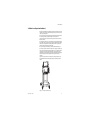
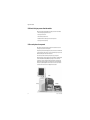
1.3 What is an Engström Ventilator?
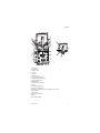
The Engström Ventilator (EV) is a flexible, adaptable, and intuitive critical care
ventilator. A wide selection of performance options gives the user full control
of the system configuration.
The EV must only be operated by authorized medical personnel well trained in
the use of this product, for patient ventilation in the intensive care
environment. It must be operated according to the instructions in this User’s
Reference manual.
The ventilator is designed to be used with infant through adult patients with a
body weight of 5 kg or greater. The EV is designed to maintain lung ventilation
in the absence of spontaneous breathing effort as well as in support of the
patient’s existing spontaneous breathing effort.
The system is designed for facility use, including within-facility transport.
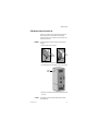
The ventilator consists of three main components: a display, a ventilator unit,
and an optional module bay. The display allows the user to interface with the
system and control settings. The ventilator unit controls electrical power,
nebulization, and pneumatic gas flow to and from the patient. The module bay
allows the integration of various patient monitoring modules with the
ventilator.
Optional accessories include an air compressor, airway modules, module
bay, humidifier and water trap mounting brackets, and auxiliary electrical
outlets.
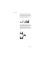
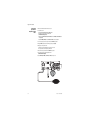
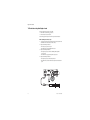
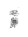
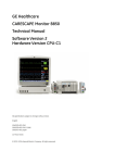
Figure 1-1 • Engström Ventilator (EV)
1505-1018-000
10/04
1-3
Engström Ventilator
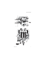
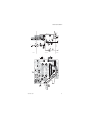
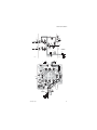
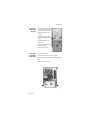
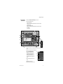
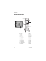
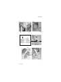
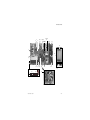
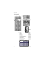
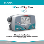
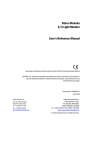
1.4 Ventilator overview
7
1
6
8 9 10 11 12
2
13
5
AB.98.011
3
4
14
AB.98.007
17 16 15
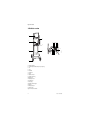
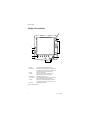
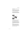
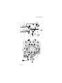
1. Module bay (optional)
2. Ventilator lock [locks Ventilator unit (item 6) to Cart (item 3)]
3. Cart
4. Caster
5. Dovetail rails
6. Ventilator unit
7. Display
8. Nebulizer connection
9. Exhalation valve housing
10. Expiratory inlet
11. Expiratory flow sensor
12. Gas exhaust port
13. Leak test plug
14. Exhalation valve housing latch
15. Water trap
16. Auxiliary pressure port
17. Inspiratory outlet
Figure 1-2 • Front view of the EV
1-4
10/04 1505-1018-000
1 Introduction
1
15
14
13
2
3
12
4
19
18
3
11
AB.98.045
5
6
2
10
17 16
7
8
AB.98.009
9
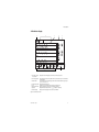
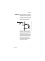
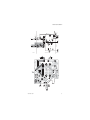
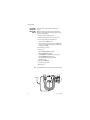
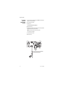
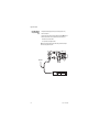
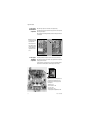
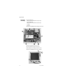
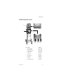
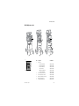
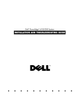
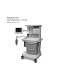
1. Display fan filter
2. Display connection
3. Module bay connection
4. AC mains inlet
5. System switch
6. Equipotential connector
7. Oxygen supply connection (pipeline)
8. Air supply connection (pipeline or compressor)
9. Module bay mounting thumbscrews
10. Ventilator unit fan filter
11. Serial communication port (RS 232 port)
12. Arm holder
13. RS 485 port (not currently supported)
14. RS 485 port (not currently supported)
15. RS 422 port (used to communicate with PC based Service Application — Refer to Section 8.5)
16. Network ID connection
17. Ethernet connection
18. DIS port (not currently supported)
19. USB port
Figure 1-3 • Back view of the E V
1505-1018-000
10/04
1-5
Engström Ventilator
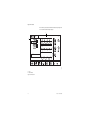
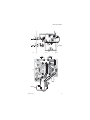
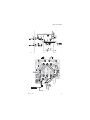
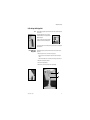
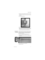
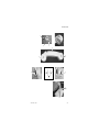
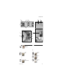
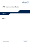
1.5 Display controls and indicators
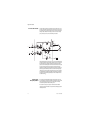
1
2
3
8
3
7
3
1
2
Alarm LEDs
Alarm Silence key
3
4
Menu keys
ComWheel
5
6
Normal Screen key
AC mains indicator
7
Quick keys
8
100% O2 key
5
AB.98.012
4
6
The red and yellow LEDs indicate the priority of active alarms.
Push to silence any active, silenceable high and medium priority alarms or
to suspend any non-active medium priority alarms. Alarm audio is silenced
or suspended for 120 seconds. Push to clear resolved alarms.
Push to show corresponding menu.
Push to select a menu item or confirm a setting. Turn clockwise or
counterclockwise to scroll menu items or change settings.
Push to remove all menus from the screen.
The green LED lights continuously when the EV is connected to an AC mains
source. The internal batteries are charging when the LED is lit.
Push to change corresponding ventilator setting. Turn the ComWheel to
make a change. Push the Quick key or ComWheel to activate the change.
Push to deliver 100% O2 for 2 minutes.
Figure 1-4 • Controls and indicators
1-6
10/04 1505-1018-000
1 Introduction
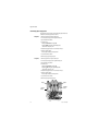
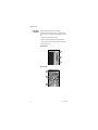
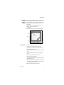
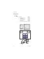
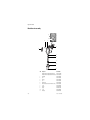
1.6 Ventilator display
1
2
3
4
5
AB.98.013
6
•
8
1
2
Alarm silence symbol
and countdown
Alarm message fields
3
Waveform fields
4
5
6
7
8
General message field
Clock
Measured value fields
Digit field
Ventilator settings
7
Displays the time remaining during an alarm silence or alarm suspend period.
Alarms will appear in order of priority. Refer to “Alarms and Troubleshooting” for more information
on alarm behavior.
The top two waveforms are permanently set to Paw and Flow. The third waveform may be selected
as CO2, O2, Vol, Paux, or Off.
Displays informational messages.
The time may be set in 12 or 24 hour format in the Time and Date menu.
Displays current measured values corresponding to the waveforms.
Displays information related to Volume, CO2, O2, Compliance or Spirometry.
Displays several of the settings for the current mode of ventilation.
Figure 1-5 • Normal Screen view
1505-1018-000
10/04
1-7
Engström Ventilator
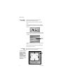
When a menu key is selected the waveform fields start at the right edge of the
menu. The entire waveform is always displayed.
2
AB.98.014
1
1. Menu
2. Waveform fields
Figure 1-6 • Menu view
1-8
10/04 1505-1018-000
1 Introduction
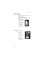
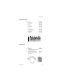
1.6.1 Using menus
Push a menu key to display the corresponding menu. Use the ComWheel to
navigate through the menu.
1
2
3
6
4
AB.91.007
Xxxxxx Xxxxxx
5
1.
2.
3.
4.
5.
6.
Menu title
Present selection
Adjustment window
Indicates submenu
Short instructions
Menu selections
Figure 1-7 • Example menu
1. Push the menu key to display the corresponding menu.
2. Turn the ComWheel counterclockwise to highlight the next menu item.
(Turn the ComWheel clockwise to highlight the previous menu item.)
3. Push the ComWheel to enter the adjustment window or a submenu.
4. Turn the ComWheel clockwise or counterclockwise to highlight the
desired selection.
5. Push the ComWheel to confirm the selection.
6. Select Normal Screen or push the Normal Screen key to exit the menu
and return to the normal monitoring display. (Select Previous Menu to
return to the last displayed menu, if available.)
1505-1018-000
10/04
1-9
Engström Ventilator
1.7 Symbols used in the manual or on the equipment
Symbols replace words on the equipment, on the display, or in
Datex-Ohmeda manuals.
Warnings and Cautions tell about the dangerous conditions that can occur if
the instructions in the manual are not followed.
Warnings tell about a condition that can cause injury to the operator or the
patient.
Cautions tell about a condition that can cause damage to the equipment.
Read and follow all warnings and cautions.
On (power)
REF
Stock number
SN
Serial number
†
y
Y
z
t
+
N
Direct current
∏
x
Alternating current
N
N
O
œ
m
w
l
p
o
wW
This way up
1-10
On for part of the equipment
Standby
Attention, refer to product instructions
IEC 60601-1
Earth ground
Equipotential connector
Lock
Variability
Plus, positive polarity
Movement in one direction
Off (power)
Off for part of the equipment
Type B protection against
electrical shock
Caution, ISO 7000-0434
Protective earth ground
Fuse
Z
T
ˆ
Unlock
Variability in steps
Minus, negative polarity
Movement in both directions
Warning, dangerous voltage
10/04 1505-1018-000
1 Introduction
1505-1018-000
Pneumatic inlet
Pneumatic outlet
Electrical input
Electrical output
Inspiratory port
Expiratory port
Electrical testing certification
Inspiratory breath identifier
Serial port
Module data indicator
Module bay port
Electronic micropump nebulizer
Auxiliary pressure port
Display signal input/output
No battery/battery failure
Battery in use. Bar indicates
amount of battery power
remaining.
Silence alarms
Submenu
Hourmeter
Drain outlet
10/04
1-11
Engström Ventilator
Air
Pump
Heavy object
USB port
Ethernet connection
134°C
Autoclavable
Network ID connection
(Datex-Ohmeda proprietary port)
ID
X1
Í
Authorized representative in the
European Community
XXXX
1-12
Not autoclavable
Systems with this mark agree with
the European Council Directive
(93/42/EEC) for Medical Devices
when they are used as specified in
their User’s Reference Manuals.
The xxxx is the certification number
of the Notified Body used by
Datex-Ohmeda’s Quality Systems.
10/04 1505-1018-000
2 Theory of Operation
In this section
2.1 Pneumatic Operation . . . . . . . . . . . . . . . . . . . . . . . . . . . . . . . . . . . . . . . . . . . . . . . . . . . . . . .2-2
2.1.1 Inspiratory circuit . . . . . . . . . . . . . . . . . . . . . . . . . . . . . . . . . . . . . . . . . . . . . . . . . . . .2-2
2.1.2 Expiratory circuit . . . . . . . . . . . . . . . . . . . . . . . . . . . . . . . . . . . . . . . . . . . . . . . . . . . . .2-7
2.1.3 Associated circuits . . . . . . . . . . . . . . . . . . . . . . . . . . . . . . . . . . . . . . . . . . . . . . . . . . .2-8
2.1.4 Electronic micropump nebulizer . . . . . . . . . . . . . . . . . . . . . . . . . . . . . . . . . . . . . . . .2-8
2.2 Electrical Operation . . . . . . . . . . . . . . . . . . . . . . . . . . . . . . . . . . . . . . . . . . . . . . . . . . . . . . . . .2-9
2.2.1 Display Unit (DU) . . . . . . . . . . . . . . . . . . . . . . . . . . . . . . . . . . . . . . . . . . . . . . . . . . . .2-9
2.2.2 Communication channels . . . . . . . . . . . . . . . . . . . . . . . . . . . . . . . . . . . . . . . . . . . 2-10
2.2.3 Ventilator Control Board - VCB . . . . . . . . . . . . . . . . . . . . . . . . . . . . . . . . . . . . . . . 2-12
2.2.4 Ventilator Monitoring Board - VMB . . . . . . . . . . . . . . . . . . . . . . . . . . . . . . . . . . . . 2-14
2.2.5 Power Management Board – PMB . . . . . . . . . . . . . . . . . . . . . . . . . . . . . . . . . . . . 2-16
2.2.6 Other Electronic Items . . . . . . . . . . . . . . . . . . . . . . . . . . . . . . . . . . . . . . . . . . . . . . 2-16
2.2.7 Motherboard (backplane) . . . . . . . . . . . . . . . . . . . . . . . . . . . . . . . . . . . . . . . . . . . 2-17
2.2.8 Monitoring Interface Board – Monitoring Module Bays . . . . . . . . . . . . . . . . . . . . 2-17
1505-1018-000
10/04
2-1
Engström Ventilator
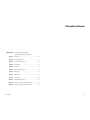
2.1 Pneumatic Operation
For a complete diagram of the pneumatic system, refer to Figure 11-2, " Vent
Engine manifold flow diagram" in Section11.
The EV requires a medical-grade oxygen (O2) and Air source ranging from 2.4
to 6.5 bar (35 to 94 psi).
The system includes two separate channels (O2 and Air) to provide dynamic
mixture control of the delivered O2 percentage.
The Air supply may include an optional compressor unit {1} for applications
where pipeline Air is not available or to provide a continued Air supply if the
pipeline supply goes down.
Air O2
{1}
Air
2.1.1 Inspiratory circuit
Compressed gas enters the EV through an inlet fitting {2} that is particular to
the institution’s supply system. The gas is filtered through a 2-micron
particulate filter {3} as it enters the ventilator’s “pneumatic engine” manifold.
A high-pressure transducer {4} having a dynamic range of 0 to 8.3 bar
(0 to 120 psi) is tapped at the outlet of the filter. This transducer monitors the
adequacy of the supply pressure. Failures of supply gas, coupling hoses or an
occluded filter are identified by the supply pressure transducer.
{4}
{2}
Primary
Inlet
2-2
{3}
Inlet
Filter
High Pressure
Transducer
P
Check
Valve
10/04 1505-1018-000
2 Theory of Operation
Next in the downstream path of flow is a check valve {5}. The check valve
prevents backflow from the EV that would possibly contaminate the supply
pressure lines. For example; if the O2 supply were to be lost, the check valve in
the O2 channel will prevent Air from moving back into the O2 supply lines.
High Pressure
Transducer
P
Primary
Inlet
Check
Valve
Inlet
Filter
{5}
Downstream from the check valve is a 172 kPa (25 psi) pressure regulator {6}.
(The regulator is a non-relieving type that does not bleed gas into the
ventilator’s enclosure.) The regulator ensures a constant pressure supply to
the flow valve {8}. The regulated supply is flow rate dependant, which is
compensated for in the flow valve’s on-site calibration.
High Pressure
Transducer
P
Primary
Inlet
Inlet
Filter
{7}
{6}
Regulator
25 psi
172 kPa
Flow
Sensor
Test
Port
T
{8}
Flow
Valve
H
Check
Valve
Between the regulator and the flow valves is the inspiratory flow sensor {7}.
The sensor is a thermal mass-flow type that injects heat into the flow stream
and monitors the associated temperature rise at a downstream location. The
temperature change is dependent on the mass flow of the flow stream and
the specific heat of the gas moving through the sensor. Since the composition
of gas in the sensor is known, a conversion of mass-flow rate to volumetric
flow at ambient conditions can be made using the ambient density of the gas.
The sensor uses a laminar (two channel) flow element to split a portion of the
flow through the sensor past the heat injection and temperature sensing
elements. The sensor is pre-calibrated and includes an electronic PCB that
produces direct digital output of mass flow through an RS-232 interface.
Individual flow sensors measure the volume of gas dispensed from the O 2 and
Air channels during inspiration and expiration. The relative proportion of gas
dispensed from each channel is continuously adjusted to precisely control the
percentage of O2 delivered to the patient.
1505-1018-000
10/04
2-3
Engström Ventilator
Downstream of the flow sensor is a flow valve {8} that meters flows from
approximately 0.05 l/min (leakage level) to a full flow value of 160 l/min. The
valve is a normally- closed proportional solenoid that is powered by a current
feedback loop. When calibrated on-site, using data from the inspiratory flow
sensor, a precise volumetric flow versus input current profile is developed that
includes both the valve and regulator characteristics.
{8}
High Pressure
Transducer
P
Primary
Inlet
Regulator
25 psi
172 kPa
Flow
Sensor
Test
Port
T
Flow
Valve
H
Check
Valve
Inlet
Filter
Following the two individual flow valves is the total flow sensor {10}. This
sensor is the same type as the individual flow sensors and is used to measure
the combined inspiratory flow being dispensed from the system. Using the
known mixture composition along with atmospheric pressure and gas
temperature information, mass-flow data from the sensor is converted to
delivered volumetric flow towards the patient. During calibration, the sensor is
checked against the output of the O2 and Air flow sensors to ensure proper
operation.
Flow
Valve
Flow
Sensor
T
Pneumatic
Resistor
H
Air
{10}
Total Flow
T
Flow
Sensor
T
Flow
Valve
Inspiratory
Effort
Valve
H
O2
2-4
H
Free Breathing
Check Valve
10/04 1505-1018-000
2 Theory of Operation
Following the total flow sensor are the free-breathing check valve {11} and the
inspiratory effort valve {12}.
During normal operation, the inspiratory effort valve is open, allowing the
free-breathing check valve to admit flow if the patient draws a significant
amount of inspiratory pressure, causing the airway pressure to become more
negative than -0.5 cm H2O. The free-breathing check valve allows the patient
to spontaneously breathe in case of a ventilation delivery failure.
On occasion, to assess the patient’s tolerance to be weaned from the
ventilator, clinicians can determine the amplitude of inspiratory effort that the
patient can create. During this “procedure”, the inspiratory effort valve is
closed, effectively locking out the free breathing valve from the patient circuit.
Flow
Valve
Flow
Sensor
T
Pneumatic
Resistor
P
H
Expiratory Press
Air
{13}
Total Flow
O2 Sensor
T
Flow
Sensor
T
H
O2
Flow
Valve
Inspiratory
Effort
Valve
H
{12}
O2
Free Breathing
Check Valve
{11}
Auxil
Tr
Next in the flow path is the O2 sensor {13}. The sensor is used to monitor the
O2 concentration produced by the combined O2 and Air flows.
The O2 sensor uses the paramagnetic principle (oxygen molecules are
attracted in magnetic fields) to measure the oxygen concentration. The sensor
includes two nitrogen-filled glass spheres mounted on a suspension
containing a conductive coil that is located in a non-uniform magnetic field.
When the system is disturbed by an impulse of current, the suspension begins
to oscillate, inducing an EMF into the coil. The oscillation period of the
induced EMF is dependent on the partial pressure of oxygen surrounding the
suspension.
As sample gas fills the sensor, oxygen that is present in the sample is
attracted into the strongest part of the magnetic field. This congregation of O 2
molecules alters the natural oscillation frequency of the suspension.
Calculations based on the difference between the oscillation period for an
oxygen sample and that for nitrogen, and readings from the absolute pressure
transducer, determine the measured O2 percentage.
1505-1018-000
10/04
2-5
Engström Ventilator
As a safety measure, a relief valve {14}, located downstream from the O 2
sensor, can be energized to vent the full flow rate of the inspiratory delivery
side of the system. If an overpressure condition is detected, the valve can be
opened by either of the EV’s two control processors. To provide redundant
safety (independent of the electronic circuits), the valve begins to
mechanically relieve pressure at a nominal 115 cm H2O.
Expiratory Zero
Valve
Flow
Valve
Flow
Sensor
T
Pneumatic
Resistor
H
Exhalation
Valve
P
Expiratory Pressure
{15}
Inspiratory Pressure
Air
P
Inspiratory Zero
Valve
Total Flow
O2 Sensor
T
Flow
Sensor
T
H
O2
Flow
Valve
Inspiratory
Effort
Valve
H
Safety
Relief Valve
O2
Free Breathing
Check Valve
{14}
Auxiliary Pressure
Transducer
Relief
The inspiratory airway pressure transducer {15}, along with its associated
zeroing valve, is located just prior to the inspiratory outlet port. This
transducer has a range of –20 to 120 cm H2O and serves as one of three
airway pressure measuring devices in the EV.
2-6
10/04 1505-1018-000
2 Theory of Operation
2.1.2 Expiratory circuit
At the expiratory side of the ventilator, a solenoid powered exhalation valve
{16} controls exhaust from the breathing circuit. The valve contains an
elastomer diaphragm that is held against a rigid seat by a solenoid (voice coil)
driven piston. The valve achieves a balance between the pressure generated
within its 21-mm diameter seat area and the force applied by the piston,
releasing exhalation flow as necessary to maintain balance. The proportional
solenoid controls the exhalation sealing pressure within a range of 0 to 100
cm H2O. Software control provides continuous oscillatory movement
(dithering) of the exhalation valve to minimize static friction effects.
{20}
Air
30 mm Male Cone
H
Pneumatic
Resistor
{18}
Expiratory Zero
Valve
Exhalation
Flow Sensor
{19}
{16}
Pneumatic
Resistor
Exhalation
Valve
P
Expiratory Pressure
From
EXP
22 / 15 mm
Male / Female
{17}
Inspiratory Pressure
P
O2 Sensor
T
H
Patient
Inspiratory Zero
Valve
Total Flow
Patient
O2
INSP
22 / 15 mm
Male / Female
To
Micropump
Nebulizer
Inspiratory
Effort
Valve
Safety
Immediately upstream of the exhalation valve is a tap for the expiratory
pressure transducer {17} and its associated zeroing valve. The expiratory
pressure tap is continuously purged with 35 ml/min of air to ensure that
exhaled condensate does not occlude the tap. The air flow is established from
the regulated Air supply using a fixed orifice (pneumatic resistor) {18}.
Downstream of the exhalation valve is the expiratory flow transducer {19}. In
principle, the transducer is similar to a hot-wire anemometer. A wire having a
large “temperature to electrical resistance” relationship is placed in the
flowstream. The wire is kept at a constant temperature using a Wheatstone
bridge circuit. The current necessary to maintain the resistance of the sensor
portion of the bridge is a function of the flow through the sensor.
At the output of the flow sensor is a flapper type check valve {20} that
prevents gas from being drawn in through the expiratory valve and minimizes
patient rebreathing in the event of a ventilator failure.
1505-1018-000
10/04
2-7
Engström Ventilator
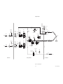
2.1.3 Associated circuits
Associated with the inspiratory and expiratory pressure transducers are two
“zeroing” solenoid valves {21} and {22}. These valves are used to disconnect
the pressure transducers from circuit pressure and vent them to atmosphere
during zero bias calibration. This zeroing procedure is conducted routinely
(every 12 hours) under the control of the Vent Engine software.
30 mm Male Cone
Flow
Valve
High Pressure
Transducer
Regulator
25 psi
172 kPa
P
Primary
Inlet
Inlet
Filter
Flow
Sensor
Test
Port
T
H
{22}
Pneumatic
Resistor
{25}
Pneumatic
Resistor
Exhalation
Valve
P
H
Expiratory Pressure
Check
Valve
Inspiratory Pressure
P
Air
O2 Sensor
H
EXP
22 / 15 mm
Male / Female
{21}
Inspiratory Zero
Valve
Total Flow
T
Exhalation
Flow Sensor
Expiratory Zero
Valve
Patient
O2
INSP
High Pressure
Transducer
P
Primary
Inlet
Inlet
Filter
Regulator
25 psi
172 kPa
Flow
Sensor
Test
Port
T
H
Flow
Valve
22 / 15 mm
Male / Female
Inspiratory
Effort
Valve
Micropump
Nebulizer
{27}
Check
Valve
Safety
Relief Valve
Free Breathing
Check Valve
O2
{23}
{24}
Auxiliary Pressure
Purge Valve
Auxiliary Pressure
Transducer
{26}
Relief
Valve
P
Paux
1/8, 3/16, 1/4 inch Stepped Hose Barb
A third (auxiliary) pressure channel {23} is used to measure additional patient
“airway” pressures at the discretion of the clinician. This port could be used to
measure circuit pressure directly at the airway, laryngeal cuff pressures or
pressures lower in the airway tract. The transducer circuit includes a valve {24}
to provide a 35 ml/min purge flow as required by the particular clinical
application. For example, in measuring airway pressure at the endotracheal
tube the purge would most likely be turned on, but for measuring laryngeal
cuff pressures (closed system) the purge would be turned off. The purge flow
is established from the regulated Air supply using a fixed orifice (pneumatic
resistor) {25}. The relief valve {26} limits pressure in the auxiliary channel to
less than 230 cm H2O.
2.1.4 Electronic
micropump nebulizer
The Aeroneb Professional Nebulizer System (Aeroneb Pro) by Aerogen, Inc.
{27} is integrated into the EV. This nebulizer is electrically connected to the EV
and uses proprietary technology to produce a fine-droplet, low-velocity
aerosolized drug delivered into the breathing circuit.
The Aeroneb Pro is designed to operate in-line with standard ventilator
circuits and mechanical ventilators. It operates without changing the patient
ventilator parameters.
2-8
10/04 1505-1018-000
2 Theory of Operation
2.2 Electrical Operation
For a complete diagram of the electrical system, refer to Figure 11-4,
"Electrical architecture" in Section11.
The EV includes 4 major processor control boards:
• the Display Unit (DU),
• the Ventilator Control Board (VCB),
• the Ventilation Monitoring Board (VMB),
• and the Power Management Board (PMB).
Two analog boards — the motherboard (backplane) and the monitoring
module power supply board — round out the electronic architecture.
2.2.1 Display Unit (DU)
The DU is physically separate from the ventilator chassis (connected through
a single cable running through the display arm). The DU contains a CPU board
based on the Elan SC520 processor. A small daughter board (DU Interface
board), provides a communications interface
between the DU’s CPU
and the remainder of the EV system. A second daughter board (DU Connector
board), provides hardware connector interfaces for the USB
,
ID
Network ID X1 , Ethernet
, and DIS (Display Interface Solution) ports.
The CPU board includes a PCMCIA (PC Card) interface.
The DU’s CPU board provides power and signals for operating the main audio
speaker and a 12 inch (30 cm) backlit color LCD display, providing an
interactive video interface. Membrane keys from three front-panel keypads
and a rotary encoder (ComWheel) complete the loop for acquiring user inputs.
The DU housing contains a continuously operating fan for temperature
reduction.
Display Unit
Keypad
Knob
LCD Display
DU Infc Bd
Display Unit
CPU Board
CPU Elan
SC520
UARTs
Speaker
PC Card
DU Conn Bd
DIS
1505-1018-000
10/04
Ethernet
Net
ID
USB
2-9
Engström Ventilator
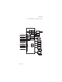
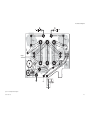
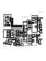
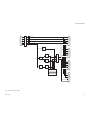
2.2.2 Communication
channels
The DU communicates
to the remainder of the EV system through the
motherboard using 5 digital channels.
[1] A 500 Kbaud, RS-485 interface (Mod Bus: Datex-Ohmeda proprietary
module communication protocol), to external monitoring modules. This
link runs through the Monitoring Module Power supply board which forms
the physical interface to the M-Gas (and ultimately other) monitoring
modules.
Additionally, the Mod Bus interfaces with the PSM (Patient Side Module)
support circuitry (future expansion).
[2] A 38.4 Kbaud, RS-422 interface relays setting and alarm annunciation
information from the VMB, and receives alarm commands and data.
[3] A 38.4 Kbaud, RS-422 interface relays setting and alarm annunciation
information from the VCB, and receives sensor data for presentation to the
user as well as alarm commands. As described later, the VMB also
communicates directly to the VCB, thus there exists a triangle of bidirectional communication paths between the DU, VCB and VMB.
[4] An RS-232 Serial port that routes to an external connector directly on the
motherboard. This link ports data from the DU to other compatible
equipment via the Ohmeda Com 1 protocol.
[5] A 38.4 Kbaud, RS-232 link to the PMB. Aside from providing battery and
power information to the DU, this link is used to confirm a “hard” power
down of the EV with user inputs to the DU being relayed to the PMB for
power down action.
2-10
10/04 1505-1018-000
2 Theory of Operation
Display Unit
RS-232
38.4 Kbaud
External I/O:
PCMCIA (2)
Display Unit CPU
RS-232 Serial
External I/O
AMD Elan SC520
Processor
RS-422
38.4 Kbaud
RS-422
38.4 Kbaud
ISA
Bus
Serial
9.6 Kbaud
External I/O:
DIS
Ethernet
Net ID
USB
Module Bay
Color LCD
EV Chassis
[1]
Mod Bus, RS-485
500 Kbaud
PSM
RS 485
RS-485
Future
Expansion 19.2 Kbaud
RS 422
RS-422
Future
Expansion 19.2 Kbaud
RS 232
VCB
Vent Control
Board
Motorola
Coldfire V4
Processor
VMB
Vent Monitor
Board
Atmel ATmega
128 Processor
[2]
RS-422
38.4 Kbaud
[3]
RS-422
38.4 Kbaud
[4]
External
I/O Serial
PMB
Power
Management
Board
Atmel ATmega
128 Processor
10/04
RS-422
921.6 Kbaud
[5]
RS-232
38.4 Kbaud
AB.98.064
RS 485
1505-1018-000
Mod Bus, RS-485
500 Kbaud
C&T 69000
Display Processsor
DU Controls
Atmel
ATmega 16
Processor
M-Gas
Intel 196
Processor
DU - UPI
Hitachi H8
Processor
2-11
Engström Ventilator
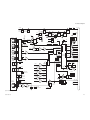
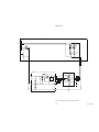
2.2.3 Ventilator
Control Board VCB
The VCB is a Motorola Coldfire V4 CPU powered assembly that:
• collects information from all EV system sensors (some indirectly from the VMB),
• and controls all actuators necessary to effect ventilation delivery.
The VCB computes and supplies all ventilation sensor monitoring data for display on
the DU. If there are alarms to be generated based on this monitoring data, the VCB
notifies the DU to post the appropriate alarm message and audio sequence. The VCB
observes the DU’s response to ensure that the alarm is adequately presented.
To control ventilation, the VCB accepts ventilation parameters from the DU. Measured
data (waveform and numeric) is also sent to the DU from the VCB. This data flow occurs
on the 38.4 Kbaud, RS-422 communications link (VCB - DU Data I/O).
The VCB also communicates directly with the VMB every 1 ms, receiving expiratory flow,
expiratory pressure and O2 sensor data on the 921.6 Kbaud, RS-422 interface (VMB
Sensor Data I/O). Barometric pressure data is also received from the VMB, but at a
lower data rate.
The following sensor information is acquired directly by the VCB:
• Air Flow/Temp sensor through the RS-232 cable interface @ 200 Hz,
• O2 Flow/Temp sensor through the RS-232 cable interface @ 200 Hz,
• Total Flow/Temp sensor through the RS-232 cable interface @ 200 Hz,
• Inspiratory Pressure sensor via a differential analog signal – 12 bits @ 1000 Hz.
• Auxiliary Pressure sensor via a differential analog signal – 12 bits @ 1000 Hz.
The VCB contains actuator drive circuits for the following:
• the Air and O2 Flow Valves,
• the Exhalation Valve,
• the Inspiratory Pressure Sensor zeroing valve
• and the Auxiliary Pressure Sensor purge flow valve.
All valve actuators are driven using current drive circuits and feedback controlled using
current sense resistors. The VCB contains digital control signals for activating the
inspiratory effort and safety relief valves (through the VMB) and the Piezo-Electric
Nebulizer.
The VCB receives 12.5 Vdc from the PMB, which it regulates down to various voltages
for use by the board’s digital circuits and analog drivers. These voltage levels are selftested on the VCB.
An additional 12.5 Vdc power line is separately connected to an auxiliary buzzer on the
VCB that provides a backup audio alarm source. The buzzer is normally on and must be
kept silent by both the VCB and through a dedicated digital line coming from the VMB.
A reset or failure of either the VCB or VMB is regarded as a system fault and the buzzer
is activated.
The VCB includes 1 MB of SRAM and 8 MB of Flash memory. The CPU is connected to a
digital watchdog circuit to monitor continuous and properly sequenced execution of
software code.
As the core processor unit for the EV, the VCB includes two external serial I/O channels:
one 19.2 Kbaud RS-422 channel (Expansion Port I/O #1 to External Connector 3) and
one 500 Kbaud RS-485 channel (Expansion Port I/O #2 to External Connector 2).
2-12
10/04 1505-1018-000
2 Theory of Operation
For further details, refer to Figure 11-9, "VCB block diagram" in Section11.
VCB
Vent Control Board
Coldfire
V4 CPU
Circuit Power
VMB Sensor
Data I/O
Expansion Port I/O #1
Expansion Port I/O #2
Insp Effort Valve
Exh Valve Closed
Safety Valve On/Off
Exh Valve On/Off
Power
Regs
12 Bit
ADC
1 MB
SRAM
V Checks
8 MB
Flash
Watchdog
Piezo-Electric
Neb Board
Air
Flow Valve
Exhal Valve
Drive w/ V & I
Sense
O2
Flow Valve
Air Valve Drive
w/ I Sense
Exhal Valve
O2 Valve Drive
w/ I Sense
16 CH
MUX
RS-422 VCB - DU Data I/O
38.4Kb
Power for Buzzer
8 UARTS
Buzzer Control
Serial
XCVRs
Buzzer Sense
Expansion Signals
Backup
Buzzer
RS-232
Air Flow/
Temp
RS-232
O2 Flow/
Temp
RS-232
Total Flow/
Temp
Insp P
AB.98.076
Current Lmt Control
Nebulizer
Insp P Zero
Valve
Aux P
Aux P Purge
Valve
1505-1018-000
10/04
2-13
Engström Ventilator
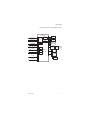
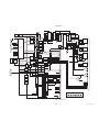
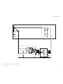
2.2.4 Ventilator
Monitoring Board - VMB
The VMB is based on an Atmel Atmega 128 CPU. The VMB performs as an
independent monitoring system that provides computational and oversight
redundancy to the DU and VCB.
The VMB independently acquires sensor data relating to the ventilator’s three
safety parameters:
• airway pressure (expiratory),
• delivered O2 percentage,
• and exhaled minute/tidal volume.
In addition, the VMB monitors the air and oxygen supply pressures:
• Air High Pressure Supply via analog cable –10 bits @ 11 Hz,
• O2 High Pressure Supply via analog cable – 10 bits @ 11 Hz,
• Expiratory flow sensor data via an I2C cable interface @ 200 Hz,
• O2 Concentration via a serial cable @ 5 Hz,
• Expiratory Airway Pressure via analog signal – 12 bits @ 1000 Hz,
• Barometric Pressure onboard VMB – 10 bits @ 11 Hz.
The VMB controls a safety valve actuator that enables it to unilaterally relieve
pressure in the breathing circuit. This allows the barotrauma hazard with its
50 ms reaction time to be independently controlled by either action of the
VCB or VMB. The hazards associated with O2 concentration (improper mixture)
and low exhaled minute volume (hypoventilation) have much slower reaction
times (on the order of minutes) and are controlled under fault conditions by
the VMB’s ability to unilaterally activate the backup buzzer.
The VMB receives 12.5 Vdc from the PMB, which it regulates down to various
voltages for use by the board’s digital circuits and analog drivers. These
voltage levels are self-tested on the VMB.
The VMB communicates directly to the DU via the bi-directional 38.4 Kbaud
RS-422 channel (VCD - DU Data I/O). A separate 921.6 Kb RS-422 link (VMB
Sensor Data I/O) is used to transmit the VMB’s sensor data to the VCB.
2-14
10/04 1505-1018-000
2 Theory of Operation
For further details, refer to Figure 11-8, "VMB block diagram" in Section11.
VMB
Vent Monitor Board
Circuit Power
Insp Effort Valve Control
Exh Valve Closed
Atmel
ATmega128
CPU
UARTS
Insp Effort
Valve
Insp Maneuver
Valve Drive
Safety
Relief Valve
Safety Valve
Drive
Air Pipeline P
Safety Valve On/Off
Exh Valve On/Off
O2 Pipeline P
I2C
VMB - DU Data I/O
RS-422
38.4 Kb
Watchdog
RS-422 VMB Sensor Data I/O
921.6 Kb
Buzzer Control
V Checks
Buzzer Sense
ADC /
MUX
Baro P
RS-232
Exp Flow
Sensor Bd
Exp Flow
Infc Bd
Exp Flow
Sensor
O2 Sensor
Exp P
Expansion Signals
1505-1018-000
10/04
AB.98.077
Circuit Power
Exp P Zero
Valve
2-15
Engström Ventilator
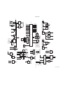
2.2.5 Power
Management Board –
PMB
The PMB is based on an Atmel Atmega 128 CPU. The PMB performs power
selection between power sources in the following order:
• AC power mains,
• External battery,
• Internal battery.
The PMB regulates the 24 Vdc power supply output down to raw 16 V and 12.5
V power rails that are used throughout the system (all boards locally regulate
from these power rails).
The PMB controls the charging operation of the internal battery, selecting
trickle, bulk, or float charge status.
The PMB communicates with the DU through the 9.6 Kbaud, RS-232 link
(PMB Data I/O). It sends status commands to the DU concerning the charge
status of the internal 24 V battery.
The PMB uses this link as a communication interlock to handle the unit
shutdown sequence. Once a signal is received by the PMB from the
mechanical On/Standby switch, the PMB prompts the DU for a confirmation
signal that shutdown is appropriate (unit is not in a ventilation therapy state).
Once the DU relays this confirmation to the PMB, the power-off sequence is
initiated.
The PMB supports the operation of the EV chassis fan and the fan on the PMB
heatsink.
2.2.6 Other Electronic
Items
The EV/5 employs a separate AC to DC switching power supply for the
providing a nominal 24v voltage level to the PMB. The power supply is capable
of regulating 150 W of power output. A power entry module contains fuses
and filters for Mains AC input cables. Finally, two internal 12v batteries are
connected in series to provide an internal backup 24v power source for the
system.
For further details, refer to Figure 11-7, "PMB block diagram" in Section11.
PMB
Power Management Board
Atmel
ATmega
128 CPU
Power Panel
Connectors
UARTS
150W Mains
Power Supply
2-16
Ext Bat
Connector
On/Standby
and
Safety Switch
Backup
Audio Power
16V
Reg
V Checks
Ext Bat
24V
PMB Data I/O
12.5V
Reg
Chassis Gnd
Power Entry
Module
PMB
Fan
Mains/Bat
Select
Vent
Engine
Fan
Fan Cntlrs
Bat Charge
Cntlr
Battery I &
V Monitor
2 - 12 V
4AHr
Batteries
10/04 1505-1018-000
2 Theory of Operation
2.2.7 Motherboard
(backplane)
The EV motherboard provides backplane connectivity for the VCB, VMB and
PMB assemblies in the EV chassis.
Analog circuits on the board provide current limiting for external peripheral
connections to ensure that the EV’s primary ventilation and monitoring
functions are not compromised by excessive power draw. In addition, 10VA
energy limit circuitry is provided for power connections within 20 cm of O 2
exhaust outlets, in order to mitigate the risk of an oxygen enriched fire.
The board features 6 external connectors that exit through a rear sheet metal
interface:
• Patient Side Module (PSM) support connector (future expansion)
• RS-485 Serial (future expansion) connector
• RS-422 Serial (future expansion) connector
• External Serial I/O connector
• Main DU connector (communication channel between DU and EV)
• Monitoring Module, Mod Bus connector
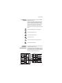
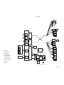
2.2.8 Monitoring
Interface Board –
Monitoring Module Bays
The EV accommodates an optional four-bay module assembly that supports
compatible Datex-Ohmeda M-series modules.
The assembly includes a Monitoring Interface Board (MIB) that communicates
with the DU through the Mod Bus connector. The MIB includes circuitry that
regulates the raw16 V power down to +15 V (unregulated), ±15 V (regulated),
and +5 V levels required by the M series monitoring modules.
I/O Panel Connectors
RS 232
Bay 1
NESTPR
Module
Bay 2
Bay 3
M-CAiOVX
Module
Monitor
Interface
Board
+15VD
-15V
+15V
+5V
Ext Serial
I/O
Filtering
RS-422
#1
Filtering
RS-485
#1
Filtering
Mod Bus
Filtering
16V
PSM
Filtering
PSM
16V
RS 422
RS 485
RS 485
Expansion Port I/O #1
12.5V
Expansion Port I/O #2
12.5V
16V
Bay 4
1505-1018-000
10/04
2-17
Notes
2-18
10/04 1505-1018-000
3 Checkout Procedure
In this section
3.1 Inspect the system . . . . . . . . . . . . . . . . . . . . . . . . . . . . . . . . . . . . . . . . . . . . . . . . . . . . . . . . .3-2
3.2 Automated Checkout . . . . . . . . . . . . . . . . . . . . . . . . . . . . . . . . . . . . . . . . . . . . . . . . . . . . . . .3-2
3.3 Backlight test . . . . . . . . . . . . . . . . . . . . . . . . . . . . . . . . . . . . . . . . . . . . . . . . . . . . . . . . . . . . . .3-3
3.4 Power failure test . . . . . . . . . . . . . . . . . . . . . . . . . . . . . . . . . . . . . . . . . . . . . . . . . . . . . . . . . . .3-3
3.5 Electrical safety tests . . . . . . . . . . . . . . . . . . . . . . . . . . . . . . . . . . . . . . . . . . . . . . . . . . . . . . .3-3
w WARNINGS
After any repair or service of the Engström Ventilator, complete all tests in this
section.
Before you do the tests in this section:
• Complete all necessary calibrations and subassembly tests. Refer to the
individual procedures for a list of necessary calibrations.
• Completely reassemble the system.
If a test failure occurs, make appropriate repairs and test for correct operation.
1505-1018-000
10/04
3-1
Engström Ventilator
3.1 Inspect the system
Before testing the system, ensure that:
•
•
•
•
•
The equipment is not damaged.
Components are correctly attached.
Pipeline gas supplies are connected.
The casters are not loose and the brakes are set and prevent movement.
The power cord is connected to a wall outlet. The mains indicator comes
on when AC Power is connected.
3.2 Automated Checkout
The EV is equipped with an automated checkout.
When in Standby, the Patient Setup menu is displayed on the normal screen.
1. Select Checkout.
2. Attach the patient circuit.
3. Occlude the patient wye.
4. Select Start Check.
• The results appear next to each check as they are completed. When
the entire checkout is finished ‘Checkout complete’ will appear and
the highlight will move to Delete Trends.
• If one or more checks fail, select Check Help for troubleshooting
tips.
5. Select Previous Menu.
Checkout includes the following checks:
• Paw Transducer Check
• Barometric Pressure Check
• Relief Valve Check
• Exhalation Valve Check
• Expiratory Flow Sensor Check
• Air Flow Sensor Check
• O2 Flow Sensor Check
• O2 Concentration Sensor Check
• Circuit Leak, Compliance, and Resistance
Note
3-2
If any of the Checks fail, refer to Section 7.1, “Troubleshooting Checkout
Failures”, to troubleshoot a specific failure.
10/04 1505-1018-000
3 Checkout Procedure
3.3 Backlight test
1. Access the Calibration menu.
• In the standby mode, push the System Setup key.
• On the System Setup menu, select Install/Service (23-17-21).
• On the Install/Service menu, select Calibration.
2. On the Calibration menu, select Backlight Test.
3. Select Start Test.
4. The display will show the test running on light 1 and then on light 2. If the
display goes completely blank or flickers during the test, one of the lights
has failed.
3.4 Power failure test
1. Connect the power cord to a wall outlet. The mains indicator on the front
panel of the Display Unit comes on when AC Power is connected.
2. Set the system switch to On and Start a case.
3. Unplug the power cord with the system turned on.
4. Make sure that the power failure alarm comes on.
5. Make sure the following message is displayed:
• ‘On battery’
6. Connect the power cable again.
7. Make sure the alarm cancels.
3.5 Electrical safety tests
w WARNING
Make sure the system is completely assembled and that the power
cords are connected as illustrated in Section 10.12. Make sure all
accessory devices are connected to electrical outlets.
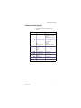
1. Connect an approved test device (for example: UL, CSA, or AAMI) and verify
that the leakage current is less than:
Voltage
Max. Leakage Current
120/100 Vac
300 µAmps
220/240 Vac
500 µAmps
2. Make sure that the resistance to ground is less than 0.2Ω between the
equipotential stud and the ground pin on the power cord.
1505-1018-000
10/04
3-3
Notes
3-4
10/04 1505-1018-000
4 Installation and Service Menus
In this section
4.1 Service and Installation menu structure . . . . . . . . . . . . . . . . . . . . . . . . . . . . . . . . . . . . . . . .4-2
4.2 Install/Service Menu (Super User) . . . . . . . . . . . . . . . . . . . . . . . . . . . . . . . . . . . . . . . . . . . . .4-3
4.2.1 Defaults . . . . . . . . . . . . . . . . . . . . . . . . . . . . . . . . . . . . . . . . . . . . . . . . . . . . . . . . . . . .4-4
4.2.2 Factory Defaults . . . . . . . . . . . . . . . . . . . . . . . . . . . . . . . . . . . . . . . . . . . . . . . . . . . . .4-5
4.3 Calibration menu . . . . . . . . . . . . . . . . . . . . . . . . . . . . . . . . . . . . . . . . . . . . . . . . . . . . . . . . . . .4-6
4.4 Service menu . . . . . . . . . . . . . . . . . . . . . . . . . . . . . . . . . . . . . . . . . . . . . . . . . . . . . . . . . . . . . .4-7
4.4.1 Configuration . . . . . . . . . . . . . . . . . . . . . . . . . . . . . . . . . . . . . . . . . . . . . . . . . . . . . . .4-8
4.4.2 Copy Configuration . . . . . . . . . . . . . . . . . . . . . . . . . . . . . . . . . . . . . . . . . . . . . . . . . . .4-9
4.4.3 Service Log menu . . . . . . . . . . . . . . . . . . . . . . . . . . . . . . . . . . . . . . . . . . . . . . . . . . 4-10
4.4.4 Software/Hardware version menu . . . . . . . . . . . . . . . . . . . . . . . . . . . . . . . . . . . . 4-11
1505-1018-000
10/04
4-1
Engström Ventilator
4.1 Service and Installation menu structure
This section describes the Service level functions that are part of the main
software installed in the ventilator.
Section 8, “Service Diagnostics and Software Download,” covers a separate
service application that loads from a PCMCIA card and is used to download
system software and run service diagnostics and other service tests.
Menu structure
The Service menu structure has two levels which are password protected:
• Install/Service (super-user)
• Service
The Install/Service level (with super-user password) supports standard
hospital preferences such as colors, units, ventilator settings and alarm
defaults, and access to the Calibration and Service menus.
The Service level (with service password) supports system configuration and
provides access to the Service Log menu.
Follow the menu structure to access the various service screens:
• on the front panel of the Display Unit, press the System Setup key to access
the System Setup menu.
• on the System Setup menu, select Install/Service to access (with superuser password) the Install/Service menu;
- select Calibration to access the Calibration menu.
- select Service to access (with service password) the Service menus.
System Setup
Install/Service
Calibration
Service
Service Log
Screen Setup
Patient Setup
Parameters Setup
System Status
Colors
Units
Show Alarm Limits
Time and Date
O2 FCV
Air FCV
Exhalation Valve
Backlight Test
Gas Calibration
Cal. Flag
Configuration
Scroll Recent
Install/Service
Normal Screen
Defaults
Calibration
Previous Menu
Service
Exit
4-2
Copy Config
Service Log
Exit
Error Log
Event Log
Alarm Log
SW HW versions
Copy Logs
Reset Logs
Previous Menu
10/04 1505-1018-000
4 Installation and Service Menus
4.2 Install/Service Menu (Super User)
Use the super-user password to access the Install/Service menu:
“23-17-21”.
Menu Item
Colors
Units
Message text
Comments
Set colors of parameters.
Change color of waveform, digits, and
trend for Paw, Flow, O2, CO2, Volume,
and Paux.
(Yellow, White, Green, Red, and Blue)
Set units of Paw, flow, CO2, height,
weight, and gas supply pressure.
Paw — kPa, hPa, cmH2O, mmHg, mbar
Flow — l/min, l/s
CO2 — %, kPa, mmHg
Height — cm, ft
Weight — kg, lb
Gas Supply Pressure — psi, kPa, bar
EXIT:
(Turn power off to exit menu.)
Show Alarm Limits
Time and Date
Defaults
Calibration
Service
Exit
1505-1018-000
10/04
Select Yes to show alarm limits in
digit fields.
Default is Yes
Change clock and calendar
functions.
Set or change default settings.
Refer to section 4.2.1
Calibrate airway gas and test
backlights.
Refer to section 4.3
Show technical data for
troubleshooting and calibration.
Refer to section 4.4
Turn power off to exit menu.
4-3
Engström Ventilator
4.2.1 Defaults
Menu Item
Scroll Settings
Default Type
Message text
Push ComWheel to scroll default
settings.
Select default patient type.
View
Adult
The selected type (Adult or Pediatric)
determines the Patient Type in the Patient
Setup Menu on power up. The
corresponding Adult or Pediatric facility
defaults are displayed for the settings on
power up. If the setting is changed within
a power cycle, those settings remain for a
specific Patient Type until they are
changed by the user or the ventilator is
turned off.
Not selectable: Heading for the following
mutually exclusive lists — Adult, Pediatric,
Factory.
Show Adult defaults and settings.
The “Adult Settings” page contains a list
of parameters or settings and the
corresponding “Saved” and “Current”
values for the Adult patient type. The
“Current” values reflect the settings in the
Vent Setup and Alarms Setup menus. Any
setting that does not have a value shows
three dashes.
Show Pediatric defaults and
settings.
The “Pediatric Settings” page contains a
list of parameters or settings and the
corresponding “Saved” and “Current”
values for the Pediatric patient type. The
“Current” values reflect the settings in the
Vent Setup and Alarms Setup menus. Any
setting that does not have a value shows
three dashes.
Factory
Show Factory defaults.
Refer to section 4.2.2
Backup
Set defaults for backup ventilation.
Pediatric
Save Current
Save current settings as facility
defaults.
The default selection is No. Common
values in the saved defaults are
overridden if another ventilation mode is
set up and saved.
Save Factory
Save factory settings as facility
defaults.
The default selection is No. If Yes is
selected, “Reset machine for defaults to
take effect.”
Previous Menu
4-4
Comments
Return to previous menu.
10/04 1505-1018-000
4 Installation and Service Menus
4.2.2 Factory Defaults
The following table lists the factory defaults for parameters and alarm limits:
Setting
Adult
Pediatric
Backup Defaults
Vent Mode
FiO2
TV
Pinsp
BiLevel
50
500
10 cmH2O (10 mbar, 1.0 kPa,
10 hPa, 8 mmHg)
10
1:2
1.70
Off
5 cmH2O (5 mbar, 0.5 kPa, 5
hPa, 4 mmHg)
30 cmH2O (30 mbar, 3 kPa,
30 hPa, 23 mmHg)
20 cmH20 (20 mbar, 2 kPa,
20 hPa, 15 mmHg)
0
100 ms
25
2 l/min (0.03 l/s)
3 l/min (0.05 l/s)
25
44
56
2 l/min (0.03 l/s)
10 l/min (0.16 l/s)
Off
Off
Off
Off
Off
Off
3% (3 kPa, 23 mmHg)
8% (8 kPa, 60 mmHg)
Vol (Volume)
BiLevel
50
100
7 cmH2O (7 mbar, 0.7 kPa, 7
hPa, 5 mmHg)
16
1:2
1.0
Off
3 cmH2O (3 mbar, 0.3 kPa, 3
hPa, 2 mmHg)
30 cmH2O (30 mbar, 3 kPa,
30 hPa, 23 mmHg)
20 cmH20 (20 mbar, 2 kPa,
20 hPa, 15 mmHg)
0
100 ms
25
1 l/min (0.02 l/s)
2 l/min (0.04 l/s)
25
44
56
1 l/min (0.02 l/s)
5 l/min (0.08 l/s)
Off
Off
Off
Off
Off
Off
3% (3 kPa, 23 mmHg)
8% (8 kPa, 60 mmHg)
Vol (Volume)
PCV
Current FiO2 setting
Compl
(Pulmonary Mechanics)
None
3
Compl
(Pulmonary Mechanics)
None
3
Rate
I:E
Tinsp
PEEP
Psupp
Pmax
Plimit
Insp Pause
Rise Time
Trig Window
Trigger
Bias Flow
End Flow
Low FiO2
High FiO2
Low MVexp
High MVexp
Low TVexp
High TVexp
Low RR
High RR
Low EtO2
High EtO2
Low EtCO2
High EtCO2
Wave Field 3
Digit Field
Split Screen
Alarm Volume
1505-1018-000
10/04
10 cmH2O (10 mbar, 1.0 kPa,
10 hPa, 8 mmHg)
12
1:2
Off
40 cmH2O (40 mbar, 4 kPa,
40 hPa, 29 mmHg)
100 ms
2 l/min (0.03 l/s)
3 l/min (0.05 l/s)
4-5
Engström Ventilator
4.3 Calibration menu
Menu Item
Message text
O2 FCV
Start O2 Flow Control Valve
calibration and leak test.
Air FCV
Start Air Flow Control Valve
calibration and leak test.
Exhalation Valve
Backlight Test
Gas Calibration
Cal. Flag
Previous Menu
Note
Comments
Patient must not be connected to
circuit during calibration. Start
Exhalation Valve calibration.
Start display backlight test.
Start gas calibration. Calibrate CO2
and O2 measurements.
Gas Calibration is enabled whenever an
MGAS module is installed. Gas
Calibration is disabled if the MGAS
module is warming up.
Turn the Calibration required
message On/Off.
When Cal. Flag is set to On, the
“Calibration required” message is
displayed in the general message area.
Return to previous menu.
The Cal. Flag menu item is used by the factory to activate the “Calibration
required” alarm. It is set as a reminder that calibrations must be performed
when the machine is set up for operation at its permanent location.
After completing the O2 FCV, Air FCV, and the Exhalation Valve calibrations,
set the Cal. Flag to Off.
4-6
10/04 1505-1018-000
4 Installation and Service Menus
4.4 Service menu
Use the service-level password to access the Service menu:
“34-22-14.”
Whenever service menu is entered, “Enter Service dd-mmm-yyyy hh:mm:ss”
is recorded in the Event log.
Menu Item
Configuration
10/04
Set language, altitude and units.
Copy Config
Save or install configuration and default settings using
memory card.
Service Log
Show error, event, and alarm histories and system
information.
Exit
1505-1018-000
Message text
Turn power off to exit menu.
4-7
Engström Ventilator
4.4.1 Configuration
4-8
Menu Item
Message text
Values
Comments
Decimal Marker
Select decimal
delineator.
0.01, 0 01 or 0,01
Default: 0.01
Language
Select language for
screen.
Chinese (simplified),
Czech, Danish,
Dutch, English,
Finnish, French,
German, Greek,
Hungarian, Italian,
Japanese,
Norwegian, Polish,
Portuguese, Russian,
Spanish, Swedish,
Turkish
Default: English
Paw
Change Paw units:
kPa, cmH2O, mbar.
kPa, cmH2O, or mbar
Default: cmH2O
Flow
Change flow units:
l/min or l/s.
l/min or l/s
Default: l/min
CO2
Change CO2 units:
%, kPa, or mmHg.
%, kPa, or mmHg
Default: %
Height
Change height units:
cm or ft.
cm or ft
Default: cm
Weight
Change weight units:
kg or lb.
kg or lb
Default: kg
Altitude
Change altitude used
for gas calculations.
–400 to 3000 m
in 100-m increments
Default: 300 m
10/04 1505-1018-000
4 Installation and Service Menus
4.4.2 Copy Configuration
Copy Configuration menu
Menu Item
Save to Card
Message text
Values
Comments
Save Configuration and
defaults to card.
<blank>, Fail, or OK.
Saves all settings
that are not hardware
dependent, including
facility defaults,
screen configuration,
trend settings, colors,
units, decimal
marker, altitude,
patient type, backup
settings, and the
Show Alarm Limits
selection.
The field is blank until the
data has either been
written to the card (OK) or
the system determines it
cannot write to the card
(Fail).
Copy from Card
Copy Configuration and
defaults from card.
When completed:
Copy from card complete.
Please reboot system.
<blank>, Fail, or OK.
The field is blank until the
data has either been read
from the card (OK) or the
system determines it
cannot read the card or
the card does not have the
required data (Fail).
Systems cannot accept configuration files from a different product model.
The software version is stored with the saved configuration. A system will
reject any configurations from other than the current version of software.
Selecting Save to Card overwrites any configuration on the card.
1505-1018-000
10/04
4-9
Engström Ventilator
4.4.3 Service Log menu
The Service log menu is a organized listing of stored events.
Menu Item
Message text
Scroll Recent
Scroll through newest entries.
Error Log
Show error history.
Event Log
Show event history.
Alarm Log
Show alarm history.
SW HW versions
Show system information.
Copy Logs
Save HW/SW info and all logs to memory card.
Reset Logs
Erase Error and Alarm log entries
Previous Menu
Return to previous menu.
Each history log shows at the top of the screen total Running Hours, the date
when the logs were last reset, and the Ventilator Serial Number.
Whenever logs are reset, “Reset Logs dd-MMM-yyy hh:mm:ss” is recorded in
the Event log.
If the logs are saved to a memory card, the ventilator’s serial number, date,
and time are saved along with the current contents of the logs.
Error Log
The Error Log lists the last 200 errors logged since the last log reset, starting
with the most recent. The system stores the last 1,000 errors logged since the
last log reset.
Event Log
The Event Log records the service history of the device. This includes: service
calibrations, entry into the service mode, options enabled, and software
installation. In the event of a board replacement, it is understood that this log
like all others could be lost.
The Event History menu lists the last 200 events logged starting with the most
recent. The Event History log stores the last 1000 events.
The Event History log cannot be reset.
Alarm Log
Copy Logs
4-10
The Alarm Log lists the last 200 alarms since the last log reset starting with
the most recent. The Alarm History log store the last 1000 entries.
The Copy Logs function copies Error, Event, and Alarm logs along with the
software/hardware configuration to a text file on a PCMCIA card.
10/04 1505-1018-000
4 Installation and Service Menus
4.4.4 Software/
Hardware
version menu
System Information menu
Turn the ComWheel to scroll through the list box.
Push the ComWheel to return to the Service menu.
X=Number, A, B, C = letter
SW HW version
System Information:
Running Hours: XXXXX
Software Release: XX.XX
Model Code: XXX
Serial Number: ABCDXXXXX
Option Package: XXX
Options Code: XXXXXXXXXXXXXXXX
VCB Software Version: XX.XX
VCB Hardware Version: XXXX-XXXX-XXX REV A
VCB Hardware Serial Number: ABCXXXXX
DU Software Version: XX.XX
DU Hardware Version: XXXX-XXXX-XXX REV A
DU Hardware Serial Number: ABCXXXXX
VMB Software Version: XX.XX
VMB Hardware Version: XXXX-XXXX-XXX REV A
VMB Hardware Serial Number: ABCXXXXX
PMB Software Version: XX.XX
PMB Hardware Version: XXXX-XXXX-XXX REV A
PMB Hardware Serial Number: ABCXXXXX
MGAS Software Version: X.X
MGAS Hardware Version: GAS SW Pr. XXXXXXX-X
MGAS Hardware Serial Number: ABCXXXXX
The MGAS information is only displayed when an Airway module is present.
1505-1018-000
10/04
4-11
Notes
4-12
10/04 1505-1018-000
5 Service Tests and Calibration
w WARNING
After adjustments and calibration are completed, always perform the checkout
procedure. Refer to Section 3 of this manual.
In this section
5.1 Calibration (super-user) . . . . . . . . . . . . . . . . . . . . . . . . . . . . . . . . . . . . . . . . . . . . . . . . . . . . .5-2
5.1.1 Calibration procedure . . . . . . . . . . . . . . . . . . . . . . . . . . . . . . . . . . . . . . . . . . . . . . . .5-3
5.2 Service level tests and calibration . . . . . . . . . . . . . . . . . . . . . . . . . . . . . . . . . . . . . . . . . . . . .5-4
5.2.1 Service application setup . . . . . . . . . . . . . . . . . . . . . . . . . . . . . . . . . . . . . . . . . . . . .5-4
5.2.2 Test setup . . . . . . . . . . . . . . . . . . . . . . . . . . . . . . . . . . . . . . . . . . . . . . . . . . . . . . . . . .5-4
5.2.3 Vent engine debris clean-out . . . . . . . . . . . . . . . . . . . . . . . . . . . . . . . . . . . . . . . . . . .5-5
5.2.4 Vent engine leak test (low pressure) . . . . . . . . . . . . . . . . . . . . . . . . . . . . . . . . . . . . .5-6
5.2.5 Vent engine leak test (high O2 pressure) . . . . . . . . . . . . . . . . . . . . . . . . . . . . . . . . .5-8
5.2.6 Vent engine leak test (high Air pressure) . . . . . . . . . . . . . . . . . . . . . . . . . . . . . . . . 5-10
5.2.7 Calibrate airway pressure transducer Zero and Span . . . . . . . . . . . . . . . . . . . . . 5-12
5.2.8 Verify operation of free- breathing valve . . . . . . . . . . . . . . . . . . . . . . . . . . . . . . . . 5-14
5.2.9 Verify operation of inspiratory effort valve . . . . . . . . . . . . . . . . . . . . . . . . . . . . . . 5-16
5.2.10 Verify operation of auxiliary pressure relief valve . . . . . . . . . . . . . . . . . . . . . . . . 5-18
5.2.11 Mechanical over-pressure valve test . . . . . . . . . . . . . . . . . . . . . . . . . . . . . . . . . 5-20
5.2.12 Verify regulator output pressure. . . . . . . . . . . . . . . . . . . . . . . . . . . . . . . . . . . . . . 5-22
1505-1018-000
10/04
5-1
Engström Ventilator
5.1 Calibration (super-user)
The EV ventilator includes integrated software that allows a qualified user to
periodically calibrate the O2 flow valve, the Air flow valves, and the Exhalation
valve.
At a minimum, these calibrations should be completed every 12 months or
when associated components are serviced or replaced. These calibrations
can be performed more frequently, as needed, for optimal performance.
The menu structure for accessing the calibration software is described in
Section 4, “Installation and Service Menus” .
Note
5-2
The Valve calibrations (Section 5.1.1) can be performed without performing
the Service level test and calibrations (Section 5.2). However, if the Service
level test and calibrations are performed, the Valve calibrations should be
performed again after the Service level test are competed (passed).
10/04 1505-1018-000
5 Service Tests and Calibration
5.1.1 Calibration
procedure
1. If present, disconnect the patient circuit from the inspiratory port (open to
atmosphere).
2. Access the Calibration menu.
• In the standby mode, push the System Setup key.
• On the System Setup menu, select Install/Service (23-17-21).
• On the Install/Service menu, select Calibration.
3. On the Calibration menu, select O2 FCV.
• On the O2 FCV menu, select Start Calibration and allow the system to
perform the calibration procedure.
• When O2 FCV calibration is complete (passed), select Previous Menu.
4. On the Calibration menu, select Air FCV.
• On the Air FCV menu, select Start Calibration and allow the system to
perform the calibration procedure.
• When Air FCV calibration is complete (passed), select Previous Menu.
5. On the Calibration menu, select Exhalation Valve.
• Connect a patient circuit and block the patient port.
• On the Exhalation Valve menu, select Start Calibration and allow the
system to perform the calibration procedure.
• When Exhalation Valve calibration is complete (passed), select Previous
Menu.
Backlight Test
6. On the Calibration menu, select Backlight Test.
7. Select Start Test.
8. The display will show the test running on light 1 and then on light 2. If the
display goes completely blank or flickers during the test, one of the lights
has failed.
9. Turn power off to exit the Install/Service menu.
1505-1018-000
10/04
5-3
Engström Ventilator
5.2 Service level tests and calibration
The service level tests require the Windows based service application as
described in Section 8.5, “EV Service Application (PC based)” .
Note
5.2.1 Service application
setup
After completing the Service level test and calibrations, perform the Valve
calibrations in Section 5.1.1.
1. Connect a Windows based PC to the serial port (RS-422 Port 3) of the EV
using a USB to RS-422 converter (Refer to section 10.1.1).
2. Start the Service Application on the PC.
• Open the VCB and VMB windows.
3. To establish communication between the PC Service Application and the
EV, start up the system and enter the Service mode.
5.2.2 Test setup
1. Connect a manual shut-off valve to each gas supply inlet.
• Remove inlet fittings from EV (ensure o-ring remains on adapter).
• Connect shut-off valve to respective EV pipeline adapter.
• Connect removed inlet fitting to respective shut-off valve.
2. Close both shut-off valves.
3. Connect pipeline supplies to each shut-off valve.
5-4
10/04 1505-1018-000
5 Service Tests and Calibration
5.2.3 Vent engine debris
clean-out
This procedure is needed only if:
• The pneumatic system within the vent engine was serviced; that is,
components were replace or removed for evaluation.
• A gas inlet filter was replaced.
Clean-out procedure
1. Open both shut-off valves.
2. Verify that the inspiratory outlet is open to atmosphere (not plugged).
3. On the VCB screen:
• Verify that the Air and O2 Flow Valves are energized ().
• Set the Air DAC counts to 60,000 (fully open).
• Set the O2 DAC counts to 60,000 (fully open).
4. After 20 seconds:
• Close both shut-off valves.
• Set the Air DAC counts to zero (closed).
• Set the O2 DAC counts to zero (closed).
Note
1505-1018-000
10/04
Closing the shut-off valves before setting the flow DAC counts to zero, bleeds
pressure from the system.
5-5
Engström Ventilator
5.2.4 Vent engine leak
test (low pressure)
1. Verify that both shut-off valves are closed.
2. On the VCB screen:
• Energize () the Auxiliary Pressure Purge valve.
• Verify that the Air Flow Valve, O2 Flow Valve and the Exhalation Flow
Valve are energized ().
• Set the Air DAC, O2 DAC, and the Exhalation DAC counts to 60,000
(this will release all pressurized gas from the system).
3. Attach the “low-pressure test tool” to the INSPiratory outlet.
4. Plug the following ports:
• Expiratory inlet.
• Auxiliary pressure port.
5. Using the low pressure test tool, increase the pressure in the low pressure
side of the system until the measured Expiratory Pressure (VMB), Auxiliary
Pressure (VCB), and Inspiratory Pressure (VCB) readings indicate 70
cmH2O.
Note: Ensure that the three pressures are stable and approximately equal
(within 5 cmH2O).
6. Once 70 cmH2O is reached, clamp the tube on the low pressure test tool
to prevent gas flow from the INSPiratory outlet.
7. On the VCB screen, select Low P Leak to start the low pressure leak test.
8. After the test is complete (15 seconds):
• Verify that the displayed Leak rate does not exceed 10 ml/min.
• If the leak rate exceeds 10 ml/min, refer to Section 7.2 to help identify
the cause of the leak.
9. Remove the test tool from the INSPiratory outlet.
10.Remove the plugs from the EXPiratory inlet and the Paux port.
AB.98.088
11.De-energize () the Auxiliary Pressure Purge valve.
5-6
10/04 1505-1018-000
5 Service Tests and Calibration
30 mm Male Cone
Exhalation
Flow Sensor
H
Pneumatic
Resistor
Expiratory Zero
Valve
High Pressure
Transducer
Regulator
25 psi
172 kPa
P
Inlet
Filter
Primary
Inlet
Flow
Sensor
Test
Port
T
Pneumatic
Resistor
Flow
Valve
H
EXP
Exhalation
Valve
P
Expiratory Pressure
Check
Valve
Inspiratory Pressure
P
Air
Inspiratory Zero
Valve
Total Flow
O2 Sensor
H
T
O2
INSP
Regulator
25 psi
172 kPa
P
Inlet
Filter
Primary
Inlet
Flow
Sensor
Test
Port
T
H
Inspiratory
Effort
Valve
Flow
Valve
Check
Valve
Safety
Relief Valve
AB.98.100
High Pressure
Transducer
Free Breathing
Check Valve
O2
Auxiliary Pressure
Transducer
Relief
Valve
P
Auxiliary Pressure
Purge Valve
Inlet Manifold
Paux
Vent Engine Manifold
Outlet Manifold
P
P
O2
Air
Air
Regulator
O2
Regulator
Air
Test Port
O2
Test
Port
O2
Flow
Sensor
O2
Flow
Valve
Total
Flow
Sensor
Air
Flow
Sensor
Air
Flow
Valve
Atmosphere
Paux
Pexp
O2 Sensor
Paux
Pinsp
AB.98.101
Relief
H
INSP
Paux
EXP
1505-1018-000
10/04
5-7
Engström Ventilator
5.2.5 Vent engine leak
test (high O2 pressure)
1. Open the manual O2 shut-off valve.
2. On the VMB screen:
• Verify that the measured O2 Supply Pressure = pipeline pressure.
• Verify that the measured Air Supply Pressure = 0.0 psig.
3. Verify that the inspiratory outlet is open to atmosphere (not plugged).
4. On the VCB screen:
• Energize () the Auxiliary Pressure Purge valve.
• Verify that the Exhalation Flow Valve is energized ().
• Set the Exhalation DAC counts to 60,000.
• Verify that the Air Flow Valve is energized ().
• Set the Air DAC counts to 60,000
(this will release any air pressure in the system).
• De-energize () the O2 Flow Valve.
5. Plug the following ports:
• INSPiratory outlet.
• EXPiratory inlet.
• Auxiliary pressure port (Paux).
6. Close the manual O2 shut-off valve.
7. On the VCB screen, select High O2 Leak to start the test.
8. After the test is complete (15 seconds):
• Verify that the displayed Leak rate does not exceed 26 ml/min.
• if not, troubleshoot for leaks in the shaded area.
9. Remove the plugs from the INSPiratory, EXPiratory, and Paux ports.
AB.98.086
10.De-energize () the Auxiliary Pressure Purge valve.
5-8
10/04 1505-1018-000
5 Service Tests and Calibration
30 mm Male Cone
H
Pneumatic
Resistor
Exhalation
Flow Sensor
Expiratory Zero
Valve
High Pressure
Transducer
Regulator
25 psi
172 kPa
P
Inlet
Filter
Primary
Inlet
Flow
Sensor
Test
Port
Pneumatic
Resistor
Flow
Valve
H
T
EXP
Exhalation
Valve
P
Expiratory Pressure
Check
Valve
Inspiratory Pressure
P
Air
Inspiratory Zero
Valve
Total Flow
O2 Sensor
T
H
O2
INSP
P
Flow
Sensor
Test
Port
T
Inspiratory
Effort
Valve
H
Safety
Relief Valve
Check
Valve
Inlet
Filter
Primary
Inlet
Regulator
25 psi
172 kPa
AB.98.102
High Pressure
Transducer
Flow
Valve
Free Breathing
Check Valve
O2
Auxiliary Pressure
Transducer
Relief
Valve
P
Auxiliary Pressure
Purge Valve
Inlet Manifold
Paux
Vent Engine Manifold
Outlet Manifold
P
P
O2
Air
Air
Regulator
O2
Regulator
Air
Test Port
O2
Test
Port
O2
Flow
Sensor
O2
Flow
Valve
Total
Flow
Sensor
Air
Flow
Sensor
Air
Flow
Valve
Atmosphere
Paux
Pexp
O2 Sensor
Paux
Pinsp
AB.98.112
Relief
H
INSP
Paux
EXP
1505-1018-000
10/04
5-9
Engström Ventilator
5.2.6 Vent engine leak
test (high Air pressure)
1. Open the manual Air shut-off valve.
2. On the VMB screen:
• Verify that the measured Air Supply Pressure = pipeline pressure.
• Verify that the measured O2 Supply Pressure = 0.0 psig.
3. Verify that the INSPiratory outlet is open to atmosphere (not plugged).
4. On the VCB screen:
• Energize () the O2 Flow Valve.
• Set the O2 DAC counts to 60,000
(this will release any O2 pressure in the system).
• De-energize () the Air Flow Valve.
5. Plug the INSPiratory outlet.
6. Close the manual Air shut-off valve.
7. On the VCB screen, select High Air Leak to start the test.
8. After the test is complete (15 seconds):
• Verify that the displayed Leak rate does not exceed 50 ml/min.
• if not, troubleshoot for leaks in the shaded area.
AB.98.093
9. Remove the plug from the INSPiratory outlet.
5-10
10/04 1505-1018-000
5 Service Tests and Calibration
30 mm Male Cone
Regulator
25 psi
172 kPa
P
Primary
Inlet
Flow
Sensor
Test
Port
Pneumatic
Resistor
EXP
Exhalation
Valve
P
H
T
Exhalation
Flow Sensor
Expiratory Zero
Valve
Flow
Valve
High Pressure
Transducer
Inlet
Filter
H
Pneumatic
Resistor
Expiratory Pressure
Check
Valve
Inspiratory Pressure
P
Air
Inspiratory Zero
Valve
Total Flow
O2 Sensor
T
H
O2
INSP
High Pressure
Transducer
P
Flow
Sensor
Test
Port
T
H
Inspiratory
Effort
Valve
Flow
Valve
Check
Valve
Inlet
Filter
Primary
Inlet
Regulator
25 psi
172 kPa
Safety
Relief Valve
Auxiliary Pressure
Transducer
AB.98.103
Free Breathing
Check Valve
O2
Relief
Valve
P
Auxiliary Pressure
Purge Valve
Inlet Manifold
Paux
Vent Engine Manifold
Outlet Manifold
P
P
O2
Air
Air
Regulator
O2
Regulator
Air
Test Port
O2
Test
Port
O2
Flow
Sensor
O2
Flow
Valve
Total
Flow
Sensor
Air
Flow
Sensor
Air
Flow
Valve
Atmosphere
Paux
Pexp
O2 Sensor
Paux
Pinsp
AB.98.113
Relief
H
INSP
Paux
EXP
1505-1018-000
10/04
5-11
Engström Ventilator
5.2.7 Calibrate
airway pressure
transducer Zero
and Span
This procedure calibrates the Inspiratory, Expiratory, and Auxiliary pressure
transducers.
Note: If Air is not available, the O2 supply can be used to calibrate the pressure
transducers. The Service Application senses which supply is available and, in step 5,
activates the corresponding flow valve.
1. Start up the system and enter the Install/Service mode.
2. Verify that the ventilator passes the low pressure leak test (Section 5.2.4).
3. Attach the test setup to the EV as shown in the illustration below.
• Connect a tee adapter to the INSPiratory outlet.
• Connect a short patient circuit tube from the tee adapter to the EXPiratory inlet.
• Connect a pressure sensing tube from the Inspiratory tee to a manometer and to
the Auxiliary pressure port (Paux).
4. Open the manual Air (O2) shut-off valve.
5. On the VCB screen:
• Verify that the Exhalation Flow Valve is energized ().
• Verify that the Air Flow Valve is energized ().
• Select Start Paw Span (~2 L/min established through Air (O2) flow valve).
• Adjust the Span DAC Value (Exhalation valve) reading
(start at approximately 40,000) until the manometer reading
equals 100 ±0.2 cmH2O.
6. At 100 cmH2O, select End Paw Span.
7. Close the manual Air (O2) shut-off valve.
8. Remove the test setup.
If the span calibration is aborted or failed, the last known good calibration will be used.
To Manometer
5-12
AB.98.089
Note
10/04 1505-1018-000
5 Service Tests and Calibration
30 mm Male Cone
Exhalation
Flow Sensor
H
Pneumatic
Resistor
Expiratory Zero
Valve
High Pressure
Transducer
Regulator
25 psi
172 kPa
P
Inlet
Filter
Primary
Inlet
Flow
Sensor
Test
Port
EXP
Pneumatic
Resistor
Flow
Valve
H
T
Exhalation
Valve
P
Expiratory Pressure
Check
Valve
Inspiratory Pressure
P
Air
Inspiratory Zero
Valve
Total Flow
O2 Sensor
T
H
O2
INSP
P
Inlet
Filter
Primary
Inlet
Regulator
25 psi
172 kPa
Flow
Valve
Flow
Sensor
Test
Port
T
Inspiratory
Effort
Valve
H
Check
Valve
Safety
Relief Valve
AB.98.105
High Pressure
Transducer
Free Breathing
Check Valve
O2
Auxiliary Pressure
Transducer
To Manometer
Relief
Valve
P
Paux
Auxiliary Pressure
Purge Valve
Inlet Manifold
Vent Engine Manifold
Outlet Manifold
P
P
O2
Air
Air
Regulator
O2
Regulator
Air
Test Port
O2
Test
Port
O2
Flow
Sensor
O2
Flow
Valve
Total
Flow
Sensor
Air
Flow
Sensor
Air
Flow
Valve
Atmosphere
Paux
Pexp
Paux
Pinsp
O2 Sensor
AB.98.115
Relief
H
INSP
To Manometer
1505-1018-000
10/04
Paux
EXP
5-13
Engström Ventilator
5.2.8 Verify operation of
free- breathing valve
1. Ensure both manual shut-off valves are closed.
2. Connect a negative pressure squeeze bulb to the INSPiratory outlet.
3. Fully depress the bulb a minimum of 10 times.
4. On the VCB screen:
• Verify that the measured Inspiratory Pressure is more positive
than - 3 cmH2O at all times.
• if not, troubleshoot the free-breathing check valve and the inspiratory
effort valve.
AB.98.091
5. Disconnect the squeeze bulb from the INSPiratory outlet.
5-14
10/04 1505-1018-000
5 Service Tests and Calibration
30 mm Male Cone
Regulator
25 psi
172 kPa
P
Inlet
Filter
Primary
Inlet
Expiratory Zero
Valve
Flow
Valve
High Pressure
Transducer
Flow
Sensor
Test
Port
T
Exhalation
Flow Sensor
H
Pneumatic
Resistor
EXP
Pneumatic
Resistor
Exhalation
Valve
P
H
Expiratory Pressure
Check
Valve
Inspiratory Pressure
P
Air
Inspiratory Zero
Valve
Total Flow
O2 Sensor
H
T
O2
INSP
High Pressure
Transducer
Regulator
25 psi
172 kPa
P
Primary
Inlet
Test
Port
T
Inspiratory
Effort
Valve
H
Check
Valve
Safety
Relief Valve
AB.98.106
Inlet
Filter
Flow
Valve
Flow
Sensor
Free Breathing
Check Valve
O2
Auxiliary Pressure
Transducer
Relief
Valve
P
Paux
Auxiliary Pressure
Purge Valve
Inlet Manifold
Vent Engine Manifold
Outlet Manifold
P
P
O2
Air
Air
Regulator
O2
Regulator
Air
Test Port
O2
Test
Port
O2
Flow
Sensor
O2
Flow
Valve
Total
Flow
Sensor
Air
Flow
Sensor
Air
Flow
Valve
Atmosphere
Paux
Pexp
O2 Sensor
Paux
Pinsp
AB.98.116
Relief
H
INSP
Paux
EXP
1505-1018-000
10/04
5-15
Engström Ventilator
5.2.9 Verify
operation of
inspiratory effort
valve
1. Ensure both manual shut-off valves are closed.
2. On the VCB screen:
• Energize () the Auxiliary Pressure Purge valve.
• Energize (close) the inspiratory effort valve
( Effort Valve Energized).
• Verify that the Air Flow Valve, O2 Flow Valve and the Exhalation Flow Valve are
energized ().
• Set the Air DAC, O2 DAC, and the Exhalation DAC counts to 60,000.
3. Connect a negative pressure squeeze bulb to the INSPiratory outlet.
4. Plug the EXPiratory inlet and the Auxiliary pressure port (Paux).
5. Fully depress the squeeze bulb.
• The bulb should not fully inflate in less than 30 seconds.
• if not, troubleshoot the inspiratory effort valve.
6. Disconnect the squeeze bulb from the INSPiratory outlet.
7. De-energize (open) the inspiratory effort valve
( Effort Valve Energized).
AB.98.087
8. Set the Air DAC, O2 DAC, and Exhalation DAC counts to zero.
5-16
10/04 1505-1018-000
5 Service Tests and Calibration
30 mm Male Cone
Exhalation
Flow Sensor
H
Pneumatic
Resistor
Expiratory Zero
Valve
High Pressure
Transducer
Regulator
25 psi
172 kPa
P
Inlet
Filter
Primary
Inlet
Flow
Sensor
Test
Port
T
EXP
Pneumatic
Resistor
Flow
Valve
H
Exhalation
Valve
P
Expiratory Pressure
Check
Valve
Inspiratory Pressure
P
Air
Inspiratory Zero
Valve
Total Flow
O2 Sensor
T
H
O2
INSP
Regulator
25 psi
172 kPa
P
Inlet
Filter
Primary
Inlet
Flow
Sensor
Test
Port
T
H
Inspiratory
Effort
Valve
Flow
Valve
Check
Valve
Safety
Relief Valve
AB.98.107
High Pressure
Transducer
Free Breathing
Check Valve
O2
Auxiliary Pressure
Transducer
Relief
Valve
P
Paux
Auxiliary Pressure
Purge Valve
Inlet Manifold
Vent Engine Manifold
Outlet Manifold
P
P
O2
Air
Air
Regulator
O2
Regulator
Air
Test Port
O2
Test
Port
O2
Flow
Sensor
O2
Flow
Valve
Total
Flow
Sensor
Air
Flow
Sensor
Air
Flow
Valve
Atmosphere
Paux
Pexp
O2 Sensor
Paux
Pinsp
AB.98.117
Relief
H
INSP
Paux
EXP
1505-1018-000
10/04
5-17
Engström Ventilator
5.2.10 Verify
operation of
auxiliary pressure
relief valve
1. Connect a manometer to the auxiliary pressure port (Paux) using a tee fitting and a
short piece of 3-mm (1/8 inch) tubing.
2. Open the manual Air shut-off valve.
3. On the VCB screen:
• Energize () the Auxiliary Pressure Purge valve.
4. Block the outlet of the tee.
5. Verify that the pressure indicated by the manometer (not the PC based application)
is greater than 90 cmH2O but less than 230 cmH2O.
Caution: Do not allow the pressure to build up over 250 cmH2O.
• if not, troubleshoot the relief valve.
6. Close the manual Air shut-off valve.
AB.98.092
7. Remove the test setup.
To Manometer
5-18
10/04 1505-1018-000
5 Service Tests and Calibration
30 mm Male Cone
Regulator
25 psi
172 kPa
P
Primary
Inlet
Inlet
Filter
Expiratory Zero
Valve
Flow
Valve
High Pressure
Transducer
Flow
Sensor
Test
Port
T
Exhalation
Flow Sensor
H
Pneumatic
Resistor
EXP
Pneumatic
Resistor
Exhalation
Valve
P
H
Expiratory Pressure
Check
Valve
Inspiratory Pressure
P
Air
Inspiratory Zero
Valve
Total Flow
O2 Sensor
T
H
O2
INSP
Regulator
25 psi
172 kPa
P
Primary
Inlet
Inlet
Filter
Flow
Valve
Flow
Sensor
Test
Port
T
Inspiratory
Effort
Valve
H
Check
Valve
AB.98.108
High Pressure
Transducer
Safety
Relief Valve
Free Breathing
Check Valve
O2
Auxiliary Pressure
Transducer
To Manometer
Relief
Valve
P
Paux
Auxiliary Pressure
Purge Valve
Inlet Manifold
Vent Engine Manifold
Outlet Manifold
P
P
O2
Air
Air
Regulator
O2
Regulator
Air
Test Port
O2
Test
Port
O2
Flow
Sensor
O2
Flow
Valve
Total
Flow
Sensor
Air
Flow
Sensor
Air
Flow
Valve
Atmosphere
Pexp
Paux
Pinsp
O2 Sensor
AB.98.118
Relief
INSP
To Manometer
H
Paux
EXP
1505-1018-000
10/04
5-19
Engström Ventilator
5.2.11 Mechanical
over-pressure valve
test
1. Verify that the ventilator passes the low pressure leak test (Section 5.2.4).
2. Turn the ventilator off.
3. Using a syringe, inject 60 ml of air into the ventilator through the INSPiratory port.
4. After the entire volume is delivered, verify that the pressure reading on the
manometer is less than 130 cmH2O.
• if not, troubleshoot the safety relief valve.
AB.98.090
Note: Pressure may spike higher than 130 cmH2O during 60 ml volume delivery if
delivered at a rate greater than 4 l/min.
To Manometer
5-20
10/04 1505-1018-000
5 Service Tests and Calibration
30 mm Male Cone
Regulator
25 psi
172 kPa
P
Inlet
Filter
Primary
Inlet
Expiratory Zero
Valve
Flow
Valve
High Pressure
Transducer
Flow
Sensor
Test
Port
T
Exhalation
Flow Sensor
H
Pneumatic
Resistor
Pneumatic
Resistor
EXP
Exhalation
Valve
P
H
Expiratory Pressure
Check
Valve
Inspiratory Pressure
P
Air
Inspiratory Zero
Valve
Total Flow
O2 Sensor
T
H
O2
INSP
P
Flow
Valve
Flow
Sensor
Test
Port
T
Inspiratory
Effort
Valve
H
Check
Valve
Inlet
Filter
Primary
Inlet
Regulator
25 psi
172 kPa
Safety
Relief Valve
Free Breathing
Check Valve
O2
Auxiliary Pressure
Transducer
To Manometer
AB.98.104
High Pressure
Transducer
Relief
Valve
P
Auxiliary Pressure
Purge Valve
Inlet Manifold
Paux
Vent Engine Manifold
Outlet Manifold
P
P
O2
Air
Air
Regulator
O2
Regulator
Air
Test Port
O2
Test
Port
O2
Flow
Sensor
O2
Flow
Valve
Total
Flow
Sensor
Air
Flow
Sensor
Air
Flow
Valve
Atmosphere
Paux
Pexp
O2 Sensor
Paux
Pinsp
AB.98.114
Relief
H
INSP
Paux
EXP
To Manometer
1505-1018-000
10/04
5-21
Engström Ventilator
5.2.12 Verify regulator output pressure
The regulator output pressure should be checked during battery replacement intervals
or whenever the unit is already opened for other reasons.
Air regulator
1. Remove the plug from the Air regulator outlet test port.
2. Connect a test pressure gauge to the Air regulator outlet test port.
3. Open the manual Air shut-off valve.
4. On the VCB screen:
• Verify that the Air Flow Valve is energized ().
• Adjust the Air DAC reading (start at approximately 9,500)
until the Air flow reading is 15 l/min.
5. Verify that the test gauge indicates 172 ± 0.69 kPa (25 ± 0.10 psi).
6. If required, adjust the regulator.
• Be sure to tighten the locking nut after adjustment.
7. Close the manual Air shut-off valve.
8. Remove the test gauge and plug the test port.
O2 regulator
1. Remove the plug from the O2 regulator outlet test port.
2. Connect a test pressure gauge to the O2 regulator outlet test port.
3. Open the manual O2 shut-off valve.
4. On the VCB screen:
• Verify that the O2 Flow Valve is energized ().
• Adjust the O2 DAC reading (start at approximately 9,500)
until the Air flow reading is 15 l/min.
5. Verify that the test gauge indicates 172 ± 0.69 kPa (25 ± 0.10 psi).
6. If required, adjust the regulator.
• Be sure to tighten the locking nut after adjustment.
7. Close the manual O2 shut-off valve.
8. Remove the test gauge and plug the test port.
O2 Adjust
O2 Regulator
Test Port
5-22
Air Adjust
Air Regulator
Test Port
10/04 1505-1018-000
5 Service Tests and Calibration
30 mm Male Cone
Primary
Inlet
Flow
Sensor
Regulator
25 psi
172 kPa
P
Inlet
Filter
Expiratory Zero
Valve
Flow
Valve
High Pressure
Transducer
Test
Port
Pneumatic
Resistor
EXP
Exhalation
Valve
P
H
T
Exhalation
Flow Sensor
H
Pneumatic
Resistor
Expiratory Pressure
Check
Valve
Inspiratory Pressure
P
Air
Inspiratory Zero
Valve
Total Flow
O2 Sensor
T
H
O2
INSP
P
Primary
Inlet
Flow
Valve
Flow
Sensor
Regulator
25 psi
172 kPa
Test
Port
T
Inspiratory
Effort
Valve
H
Check
Valve
Inlet
Filter
Safety
Relief Valve
AB.98.109
High Pressure
Transducer
Free Breathing
Check Valve
O2
Auxiliary Pressure
Transducer
Relief
Valve
P
Auxiliary Pressure
Purge Valve
Paux
Inlet Manifold
Vent Engine Manifold
Outlet Manifold
P
P
O2
Air
Air
Regulator
O2
Regulator
Air
Test Port
O2
Test
Port
O2
Flow
Sensor
O2
Flow
Valve
Total
Flow
Sensor
Air
Flow
Sensor
Air
Flow
Valve
Atmosphere
Paux
Pexp
O2 Sensor
Paux
Pinsp
AB.98.119
Relief
H
INSP
Paux
EXP
1505-1018-000
10/04
5-23
Notes
5-24
10/04 1505-1018-000
6 Maintenance
In this section
This section covers the regular maintenance procedures (minimum requirements)
needed to make sure that the Engström Ventilator operates to specifications.
6.1 Engström Ventilator planned maintenance . . . . . . . . . . . . . . . . . . . . . . . . . . . . . . . . . . . . . .6-2
6.1.1 Every twelve (12) months . . . . . . . . . . . . . . . . . . . . . . . . . . . . . . . . . . . . . . . . . . . . . .6-2
6.1.2 Every forty-eight (48) months . . . . . . . . . . . . . . . . . . . . . . . . . . . . . . . . . . . . . . . . . .6-2
6.2 Battery capacity test . . . . . . . . . . . . . . . . . . . . . . . . . . . . . . . . . . . . . . . . . . . . . . . . . . . . . . . .6-3
w WARNINGS
Do not perform testing or maintenance on the Engström Ventilator while it is being
used on a patient. Possible injury can result.
Items can be contaminated due to infectious patients. Wear sterile rubber
gloves. Contamination can spread to you and others.
Obey infection control and safety procedures. Used equipment may contain
blood and body fluids.
1505-1018-000
10/04
6-1
Engström Ventilator
6.1 Engström Ventilator planned maintenance
Serial Number:
Date: (YY/MM/DD)
Hospital:
Performed by:
12 months
24 month
6.1.1 Every twelve
(12) months
48 month
/
/
______________________
Perform the following steps every 12 months.
For details, refer to the sections listed.
1. If required, adjust the Display Unit arm joints (Section 9.5).
2. If required, adjust patient monitoring module rack arm.
3. Visually inspect Vent Engine fan filter. Clean or replace as needed.
4. Visually inspect Display Unit fan filter. Clean or replace as needed.
5. Visually inspect exhalation valve assembly. Clean or replace as needed.
6. Visually inspect gas inlet filters (O2 and Air). Replace as needed.
7. Complete the battery capacity test (Section 6.2).
8. Electrical safety tests (Section 3.5).
9. Complete all Service level tests and calibrations (Section 5.2).
10. Complete all Super-User level tests and calibrations (Section 5.1).
11. Complete the Checkout procedure (Section 3).
6.1.2 Every forty-eight
(48) months
In addition to the 12-month requirements, replace the following parts every
48 months. All parts should be replaced before performing the checks, tests,
and calibrations.
1. Replace the system batteries* (Stock Number 1009-5682-000).
*Note: Refer to the “Battery capacity test” in Section 6.2.
6-2
10/04 1505-1018-000
6 Maintenance
6.2 Battery capacity test
Although replacement of the backup batteries is recommended at the end of
4 years, batteries that pass the capacity test can be considered viable for
battery backup of the system for up to 6 years at the discretion of the hospital.
Before testing the batteries, ensure that they are fully charged.
Test procedure
1. Turn the system on and start a case (simulated).
2. Disconnect the power cord from the mains outlet.
3. Allow the system to run on battery until it does an orderly shutdown.
4. Reconnect the power cord to a mains outlet.
5. Boot the system with the PCMCIA Service Application and access the
Power Diagnostics function as detailed in Section 8.
• On the Main Menu of the Service Application, select Power Diagnostics.
• On the Power Diagnostic menu, select Power Control.
6. Page 1 of the Power Controller Power Diagnostics screen shows the ‘Date
battery Tested’ (the last full battery discharge) and the ‘Discharge Time’.
• If the ‘Discharge Time’ is greater than 60 minutes, the batteries can be
left in service for one more year.
• If the ‘Discharge Time’ is less than 60 minutes, both batteries should be
replaced.
1505-1018-000
10/04
6-3
Notes
6-4
10/04 1505-1018-000
7 Troubleshooting
In this section
7.1 Troubleshooting Checkout Failures . . . . . . . . . . . . . . . . . . . . . . . . . . . . . . . . . . . . . . . . . . . .7-2
7.1.1 Paw Transducer Check . . . . . . . . . . . . . . . . . . . . . . . . . . . . . . . . . . . . . . . . . . . . . . . .7-2
7.1.2 Barometric pressure test . . . . . . . . . . . . . . . . . . . . . . . . . . . . . . . . . . . . . . . . . . . . . .7-2
7.1.3 Low Pressure Leak and Compliance Check . . . . . . . . . . . . . . . . . . . . . . . . . . . . . . .7-3
7.1.4 Safety Valve Relief and Back Pressure . . . . . . . . . . . . . . . . . . . . . . . . . . . . . . . . . . .7-3
7.1.5 Exhalation Valve Calibration Check . . . . . . . . . . . . . . . . . . . . . . . . . . . . . . . . . . . . . .7-4
7.1.6 Exhalation Flow Sensor Calibration Test . . . . . . . . . . . . . . . . . . . . . . . . . . . . . . . . . .7-4
7.1.7 Measure Breathing Circuit Resistance . . . . . . . . . . . . . . . . . . . . . . . . . . . . . . . . . . .7-4
7.1.8 Air Inspiratory Flow Sensor Calibration Check . . . . . . . . . . . . . . . . . . . . . . . . . . . . .7-5
7.1.9 O2 Inspiratory Flow Sensor Calibration Check . . . . . . . . . . . . . . . . . . . . . . . . . . . . .7-5
7.1.10 O2 Sensor Test and Calibration . . . . . . . . . . . . . . . . . . . . . . . . . . . . . . . . . . . . . . . .7-5
7.2 Troubleshooting Vent Engine Leaks . . . . . . . . . . . . . . . . . . . . . . . . . . . . . . . . . . . . . . . . . . . .7-6
7.3 Alarm message troubleshooting chart . . . . . . . . . . . . . . . . . . . . . . . . . . . . . . . . . . . . . . . . 7-10
7.4 Troubleshooting Service App messages . . . . . . . . . . . . . . . . . . . . . . . . . . . . . . . . . . . . . . 7-26
1505-1018-000
10/04
7-1
Engström Ventilator
7.1 Troubleshooting Checkout Failures
If the Automated Checkout (Section 3.2) results in failures, refer to the
following sections to troubleshoot a specific failure.
7.1.1
Paw Transducer Check
The Paw Transducer Check can indicate a failure from four conditions:
1. Inspiratory Pressure Sensor Zero Failure:
Test results indicate Fail and the Pinsp sensor out of range message is
displayed.
• Ensure proper connections.
• Replace the Inspiratory Pressure Sensor board.
• Replace the Inspiratory Zero Valve
• Replace the Vent Control board (VCB).
2. Expiratory Pressure Sensor Zero Failure:
Test results indicate Fail and Pexp sensor out of range message is
displayed.
• Ensure proper connections.
• Replace the Expiratory Pressure Sensor board.
• Replace the Expiratory Zero Valve.
• Replace the Vent Monitor board (VMB).
3. Cannot achieve 34 cmH2O pressure:
Test results indicate Fail but no alarm message is displayed.
• Ensure supply gas is connected.
• Continue with other tests. If a significant leak is indicated during the Low
Pressure Leak test, repair the leak then repeat this check.
• Check respective Flow Control Valve for proper operation.
4. Paw insp and Paw exp are not within 4 cmH2O when pressurized to
34 cm H2O.
Test results indicate Fail but no alarm message is displayed.
• Use the Service Application to calibrate sensors (Section 5.2.7).
• Replace the affected Sensor board(s) or Zero valves, if calibration fails.
If this check fails, all ventilation modes will still be available.
7.1.2
Barometric pressure test
A failure indicates that the difference between calculated barometric
pressure based on the input altitude, and the measured barometric pressure
is greater than 20%.
• Verify correct altitude setting.
• If setting is correct, calibrate the barometric sensor (Section 8.7.4).
• Replace the Vent Monitor board (VMB) - recalibrate barometric sensor.
If this check fails, all ventilator modes will still be available and the
calculations will use the input altitude as basis for absolute pressure.
7-2
10/04 1505-1018-000
7 Troubleshooting
7.1.3
Low Pressure Leak and
Compliance Check
No failures will be indicated. If there are errors in the calculation (negative
values, divide by zero, etc.) the results will be dashed. The results of this
calculation will be displayed after the Safety Relief Valve test is completed.
1. The first calculation is compliance and is based on the amount of time it
takes for a 3 l/min flow to create 34 cmH2O of pressure at the Pexp sensor.
If this pressure cannot be achieved, no compliance information will be
available.
2. The second calculation is the low pressure leak rate. It is based on the
amount of pressure decay from 25 cmH2O pressure in approximately 3
seconds. If the leak rate is greater than 1 L/min (@ 25 cmH 2O), the leak and
compliance values will be dashed. This value can be useful in diagnosing
other failures during checkout.
3. Finally, a correction based on the leak rate is applied to the compliance
calculation and the information can be displayed.
7.1.4
Safety Valve Relief and
Back Pressure
The Safety Valve Relief test checks the ability of the Safety Relief Valve to
relieve all patient pressure on demand. Failures include:
1. Cannot achieve 30 cmH2O pressure.
The test will indicate Fail but no alarm message is displayed.
• Ensure supply gas is connected.
• A leak is indicated; repair the leak then repeat this check.
2. Once pressure stabilizes, the Safety Relief Valve is opened. If Pexp does not
go to less than 2 cmH2O within 250 msec, the test will indicate Fail and
Relief Valve Failure message will be displayed.
Use the Service Application to simulate this test.
a. If pressure remains significantly above 2 cmH2O:
• Check the connections to the safety relief valve.
• Ensure seat/seal interface is clean.
• Replace the Manifold Assembly.
b. If pressure is only slightly above 2 cmH2O:
• Re-zero pressure sensors.
• Ensure seat/seal interface is clean.
• If Exhalation Valve Calibration Check also fails, replace the Pexp
sensor.
• Repeat check.
3. If a flow of 75 l/min creates more than 10 cmH2O pressure at Pexp sensor
with the safety relief valve open, the test will indicate Fail and Relief Valve
Failure message will be displayed.
Use Service Application to simulate this test.
• Check the connections to the safety relief valve.
• Replace the Manifold Assembly.
If this test fails, no mechanical ventilation is allowed.
1505-1018-000
10/04
7-3
Engström Ventilator
7.1.5
Exhalation Valve
Calibration Check
The Exhalation Valve Calibration check uses the same relief test as above
except with the Exhalation valve instead of the Safety Relief valve.
1. Cannot achieve 34 cmH2O pressure.
The test will indicate Fail but no alarm message is displayed.
• Ensure supply gas is connected.
• A leak is indicated; repair the leak then repeat this check.
2. If both the Relief Valve and Exhalation Valve tests fail and the leak rate is
less than 2000, the most likely problem is with the Pexp Sensor not
returning to zero:
• Use the Service Application to apply 34 cmH2O of pressure until stable,
then release the pressure using either the Exhalation Valve or the Safety
Relief Valve. The Pexp value must return to less than 2 within 250 msec.
If not, re-zero and repeat or replace the Pexp sensor.
3. If only this check is failing:
a. Use the Service Application to verify at least 3 l/min is generated by
the FCV. If not:
• Recalibrate the FCV.
• Replace the FCV.
b. Remove the Expiratory flow sensor.
• If the check passes, replace the Expiratory Flow Sensor.
c. Remove the Exhalation Valve Assembly and ensure the Voice coil shaft
is clean and dry and moves freely without binding.
d. Replace the Exhalation Valve Assembly.
e. Replace the Voice coil assembly.
If this check fails, all ventilator modes will still be available.
7.1.6
Exhalation Flow Sensor
Calibration Test
The Exhalation Flow Sensor Calibration test compares the Exhalation Flow
Sensor output to the Total Flow Sensor output.
1. If only this test fails, replace the Exhalation Flow Sensor.
2. If the Air and/or O2 Inspiratory Flow Sensor calibration checks also fail, use
the Service Application to determine the accuracy of the Total Flow Sensor.
If this test fails, all ventilator functions will still be available. The message
Flow Sensor Error will be displayed.
7.1.7
Measure Breathing
Circuit Resistance
7-4
The breathing circuit resistance is calculated from the amount of resistance
created when 60 l/min is flowing through the circuit. It is calculated and
displayed on the bottom of the screen. It represents the resistance of 1/2 of
the breathing circuit.
10/04 1505-1018-000
7 Troubleshooting
7.1.8
Air Inspiratory Flow
Sensor Calibration Check
The Air Inspiratory Flow Sensor Calibration check verifies that the Air Flow
Sensor is functioning and compares the flow and temperature measurements
with the total flow sensor.
1. If both the Air and O2 Flow Sensors fail this check, replace the Total Flow
Sensor.
2. Otherwise, replace the Air Flow Sensor.
If this check fails, all ventilator functions will still be available. The message
FlAir Control Error will be displayed.
7.1.9
O2 Inspiratory Flow
Sensor Calibration Check
This check verifies that the O2 Flow Sensor is functioning and compares the
flow and temperature measurements with the total flow sensor.
1. If both the Air and O2 Flow Sensors fail this check, replace the Total Flow
Sensor.
2. Otherwise, replace the O2 Flow Sensor.
If this check fails, all ventilator functions will still be available. The message
FlO2 Control Error will be displayed.
7.1.10
O2 Sensor Test and
Calibration
This test/calibration will only be performed if both Air and O 2 are connected.
The O2 offset is calibrated while flowing 30 l/min of Air and the O 2 gain is
calibrated with 30 l/min of O2.
Calibration is verified by flowing 15 l/min Air and 15 l/min O 2 and comparing
the sensor output to the calculated valve (approximately 60.5%).
If this check fails, all ventilator functions will still be available.
1505-1018-000
10/04
7-5
Engström Ventilator
7.2 Troubleshooting Vent Engine Leaks
If the vent engine leak test (Section 5.2.4) fails,
• either if unable to build 70 cmH2O pressure,
• or if the leak rate exceeds 10 ml/min,
the following steps will help to narrow down the possible leak locations.
While retaining the leak test setup:
1. Close the Air and O2 flow valves to limit the components tested (remove the
checkmarks from the boxes next to the DAC counts).
2. Repeat the Vent Engine Leak Test.
• If the test passes, proceed to step 5.
• If the leak remains, toggle the Effort Valve closed.
3. Repeat the Vent Engine Leak Test.
• If the system passes, check the Free Breathing Valve diaphram
and o-ring seal.
• If the leak remains, toggle the safety valve open/closed.
4. Repeat the Vent Engine Leak Test.
AB.98.088
• If the system passes, check the safety valve seal.
• If the leak remains, check the individual components in the Total Flow
path.
7-6
10/04 1505-1018-000
7 Troubleshooting
30 mm Male Cone
Regulator
25 psi
172 kPa
P
Inlet
Filter
Primary
Inlet
Expiratory Zero
Valve
Flow
Valve
High Pressure
Transducer
Flow
Sensor
Test
Port
T
Exhalation
Flow Sensor
H
Pneumatic
Resistor
Pneumatic
Resistor
EXP
Exhalation
Valve
P
H
Expiratory Pressure
Check
Valve
Inspiratory Pressure
P
Air
Inspiratory Zero
Valve
Total Flow
O2 Sensor
H
T
O2
INSP
P
Inlet
Filter
Primary
Inlet
Flow
Valve
Flow
Sensor
Test
Port
T
Inspiratory
Effort
Valve
H
Check
Valve
Safety
Relief Valve
Free Breathing
Check Valve
O2
Auxiliary Pressure
Transducer
AB.98.110
Regulator
25 psi
172 kPa
AB.98.100
High Pressure
Transducer
Relief
Valve
P
Auxiliary Pressure
Purge Valve
Inlet Manifold
Paux
Vent Engine Manifold
Outlet Manifold
P
P
O2
Air
Air
Regulator
O2
Regulator
Air
Test Port
O2
Test
Port
O2
Flow
Sensor
O2
Flow
Valve
Total
Flow
Sensor
Air
Flow
Sensor
Air
Flow
Valve
Atmosphere
Paux
Pexp
O2 Sensor
Paux
Pinsp
AB.98.101
AB.98.120
Relief
H
INSP
Paux
EXP
1505-1018-000
10/04
7-7
Engström Ventilator
5. Open only the O2 flow valve by checking the O2 Flow Valve box (verify that
60000 DAC counts are set).
6. Repeat the Vent Engine Leak Test.
• If the test fails, check the individual components in the O 2 Flow path.
• If the test passes, check the individual components in the Air Flow path.
7-8
10/04 1505-1018-000
7 Troubleshooting
30 mm Male Cone
Regulator
25 psi
172 kPa
P
Inlet
Filter
Primary
Inlet
Expiratory Zero
Valve
Flow
Valve
High Pressure
Transducer
Flow
Sensor
Test
Port
T
Exhalation
Flow Sensor
H
Pneumatic
Resistor
Pneumatic
Resistor
EXP
Exhalation
Valve
P
H
Expiratory Pressure
Check
Valve
Inspiratory Pressure
P
Air
Inspiratory Zero
Valve
Total Flow
O2 Sensor
H
T
O2
INSP
Regulator
25 psi
172 kPa
P
Inlet
Filter
Primary
Inlet
Test
Port
Flow
Sensor
T
H
Inspiratory
Effort
Valve
Flow
Valve
Check
Valve
Safety
Relief Valve
AB.98.111
High Pressure
Transducer
Free Breathing
Check Valve
O2
Auxiliary Pressure
Transducer
Relief
Valve
P
Auxiliary Pressure
Purge Valve
Inlet Manifold
Paux
Vent Engine Manifold
Outlet Manifold
P
P
O2
Air
Air
Regulator
O2
Regulator
Air
Test Port
O2
Test
Port
O2
Flow
Sensor
O2
Flow
Valve
Total
Flow
Sensor
Air
Flow
Sensor
Air
Flow
Valve
Atmosphere
Paux
Pexp
O2 Sensor
Paux
Pinsp
AB.98.121
Relief
H
INSP
Paux
EXP
1505-1018-000
10/04
7-9
Engström Ventilator
7.3 Alarm message troubleshooting chart
Note:
Whenever “Check/replace harness” is indicated, ensure that all terminals are
fully inserted into the connector body window and that all wires are properly
crimped.
Troubleshooting guidelines are listed in order of probability. The entire list
does not need to be carried out if the problem is resolved. The list may not
include all possible solutions.
• Alarm message = display message
• Alarm ID = message in Error log or Event log
Alarm message
Alarm ID
Priority
Alarm Condition
Special Behavior/Comments
• Action/Troubleshooting
-none-
DU RAM Error
Failed
Self test failure or multi bit error
detected.
-none-
Therapy Power Off
High
Power switch is set to Off.
Run Backup Ventilation if in
Therapy.
• Normal operation if On/Standby switch is moved to standby while in therapy.
• Verify vent is in standby state prior to turning power On/Standby switch to standby.
• Check/replace harness to On/Standby switch.
• Check/replace On/Standby switch.
• Check/replace PMB.
Air supply
pressure high
Air Supply Pres High
Low
Air supply pressure > 95 psig for more
than 0.5 seconds
• Check air supply.
• Disconnect sensor and verify output is zero gauge pressure.
• Interchange harness connections on both supply pressure sensors.
• If alarm follows the sensor, replace supply pressure sensor.
• If not, check/replace VMB.
Air supply
pressure low
Air Supply Pres Low
Medium Air supply pressure < 24.3 psig for
more than 0.5 seconds
Unit shuts down Air supply and
delivers 100% Oxygen
Flow Wave:
O2 only
• Check air supply.
• Disconnect sensor and verify output is zero gauge pressure.
• Interchange harness connections on both supply pressure sensors.
• If alarm follows the sensor, check sensor connector terminals. Replace supply pressure sensor if necessary.
• If not, check/replace harness.
• If not harness, check/replace VMB.
7-10
10/04 1505-1018-000
7 Troubleshooting
Alarm message
Alarm ID
Priority
Alarm Condition
Special Behavior/Comments
• Action/Troubleshooting
Air temp high
Temp High
High
Total flow sensor temperature > 48 C
Flow Wave:
O2 only
Switch to 100% O2.
Air is turned off regardless of
other alarm conditions (for
example, O2 Supply Low).
When the condition clears, the
vent changes back to previous
known good set O2 mixture.
• Check inlet air temperature.
• Use Service App to check temperatures of air and total flow sensors.
• If inlet air temp is NOT high, and if temp from total flow sensor reports more than 9°C higher than the air
sensor, replace Total Flow Sensor.
• With a air flow of approximately 10 l/min, verify air and total flows are within 10% of each other.
Air temp sensor
error
Air Temperature Sensor Low
Failure
Out of range air temperature sensor
data (range is 0-60 degrees C).
Use total flow temperature for
all air flow sensor calculations,
including alarms.
If total flow sensor
temperature not available, use
50°C.
• Check inlet air temperature.
• If comm. Failure alarm is also active, check harness connections.
• With gas supplies disconnected and system temperature stabilized, use Service App to check temperatures
of air and total flow sensors. Air flow sensor and total flow sensor shall not differ by more than 9°C.
• Replace sensors.
Backup audio
failure
Backup Buzzer POST
Medium Current to buzzer indicates audio is not This alarm is logged at startsounding.
up and can be de-escalated
but cannot be cleared from
the screen.
• Check harness connection between PMB/On-Standby switch.
• Verify buzzer current with voltage measurement at TP15 on VCB. If voltage IS NOT present, replace PMB. If
voltage IS present, replace VCB.
Backup mode
active
Backup Mode Active
Medium Spontaneous breathing is insufficient Uses PCV mode and preset
or Display Unit failure.
settings (customer
System goes into Backup Ventilation configurable).
mode.
• Ensure the patient’s spontaneous breathing and ventilatory support is adequate. This alarm could be
triggered by user errors regarding patient ventilation requirements. See URM for details.
• Check error log for communication errors or DU errors.
1505-1018-000
10/04
7-11
Engström Ventilator
Alarm message
Alarm ID
Priority
Alarm Condition
Special Behavior/Comments
• Action/Troubleshooting
Check D-fend
CO2 or O2 wave
instruction:
Check D-fend.
Wait 30 sec and
press Normal
Screen to
continue.
MGAS Sample Line Not Medium MGAS communicates the sample
Connected >40 Sec
tubing or the D-fend module is not
installed.
The pump turns Off.
If Normal Screen is selected
the DU commands the MGAS
to start sampling again.
• Check that the sample tube is connected.
• Check that the water trap is connected.
• Check that the gas outlet is not blocked.
• Replace Module.
Check sample
gas out
MGAS Check Sample
Gas Out > 20 Sec
Medium MGAS communicates continuous
occlusion for 20 seconds
CO2 or O2
waveform
instruction:
Check sample gas
out. Wait 30 sec
and press Normal
Screen to
continue.
The pump turns Off.
If Normal Screen is selected,
the DU commands the MGAS
to start sampling again.
• Check the gas outlet.
• Replace module.
Connect
nebulizer
Nebulizer not
Connected
Low
Nebulizer disconnected while
nebulization procedure is running.
High
Key pad controller fails to send life tick DU to allow power off
for greater than 10 seconds
confirmation, even in Therapy.
(The Power lock popup will not
appear.)
• Re-connect Nebulizer.
• Replace Nebulizer cable.
• Replace Nebulizer head.
• Replace Nebulizer board.
Controls frozen.
Need service
Front Panel Com Fail
• Cycle power
• Replace Keypad Controller
Exp flow sensor
failure
Exhalation Flow Sensor High
Communications
Failure
Failed communications with exhalation Use open loop pressure
flow sensor.
control.
• Check harness connection between VMB and exhalation flow sensor PCB.
• Replace exhalation flow sensor PCB.
• Replace VMB.
Fans require
service
Fan Fail
Medium Fan Power Status Bits for main fan or
vicor fan is low.
• Check connections to fans.
• Replace broken fan(s).
7-12
10/04 1505-1018-000
7 Troubleshooting
Alarm message
Alarm ID
Priority
Alarm Condition
Special Behavior/Comments
• Action/Troubleshooting
FiO2 control error
Air Flow Sensor
Communications
Failure
Medium Loss of communication.
Use Open Loop valve mixture
control.
Return to closed loop volume
delivery control when cleared.
• Check Error Log for Air/O2 Insp Flow Sensor Supply Voltage.
• If yes:
-Disconnect vent engine harness at air flow sensor. If voltage error stops, replace air flow sensor.
-Disconnect vent engine harness at O2 flow sensor. If voltage error stops, replace O2 flow sensor.
-Disconnect vent engine harness at VCB. If voltage error stops, replace harness.
• If no:
-Check connection to Air Flow Sensor.
-Interchange harness connection between air and total flow sensor.
-If problem stays with sensor, replace sensor. If alarm follows harness, check/replace harness. If harness is
OK, replace VCB.
FiO2 control error
O2 Flow Sensor
Communications
Failure
Medium Loss of communication.
Use Open Loop valve mixture
control.
Return to closed loop volume
delivery control when cleared.
• Check Error Log for Air/O2 Insp Flow Sensor Supply Voltage.
• If yes:
-Disconnect vent engine harness at air flow sensor. If voltage error stops, replace air flow sensor.
-Disconnect vent engine harness at O2 flow sensor. If voltage error stops, replace O2 flow sensor.
-Disconnect vent engine harness at VCB. If voltage error stops, replace harness.
• If no:
-Check connection to O2 Flow Sensor.
-Interchange harness connection between O2 and total flow sensor.
-If problem stays with sensor, replace sensor. If alarm follows harness, check/replace harness. If harness is
OK, replace VCB.
Flow sensor error
Exhalation Flow Sensor Medium (TVexp – TVinsp) > (0.3* TVinsp) or
Comparison
100 mL whichever is greater for 6
consecutive breaths.
Freeze vent engine volume
compensation on first breath
detected.
• Using Service App, verify Inspiratory flows match Expiratory flow within tolerance stated above.
• Replace expiratory sensor as necessary.
• Replace exhalation flow sensor board (EFSB).
Internal power
failure
PMB DC-DC Fail
Medium AC supply is OK but batteries are being
discharged.
• Check screw terminal connections and harness between AC-DC power supply and PMB
• Check fuse F1. If not OK, replace PMB.
• Replace AC-DC power supply.
Mixed gas temp
sensor error
Total Flow Temperature Low
Sensor Failure
Out of range total temperature sensor Use air flow temperature for
data.
total flow sensor calculations,
including alarms.
If air flow sensor temperature
not available use 50°C.
• Check inlet air temperature.
• If comm. Failure alarm is also active, check harness connections.
• With gas supplies disconnected and system temperature stabilized, use Service App to check temperatures
of air and total flow sensors. If either reports temperature out of range (0 to 60°C), replace that sensor.
1505-1018-000
10/04
7-13
Engström Ventilator
Alarm message
Alarm ID
Priority
Alarm Condition
Special Behavior/Comments
• Action/Troubleshooting
Module fail. No
CO2, O2 data
MGAS Sensor Inop > XX Medium MGAS communicates hardware failure
(RAM failure, ROM checksum error,
Error in CPU EEPROM, Error O2 preamp
EEPROM, Error in SSSboard EEPROM,
Voltage error, or Lamp control failure.)
• Replace Module
Module not
compatible
Module Not Compatible Low
The monitoring module detected is not
compatible with system software. The
EV is designed to work with the
following Compact Airway Modules:
SW Version 3.2 and above of M-C, MCO, M-COV, M-COVX, M-CAiO, MCAiOV, and M-CAiOVX.
• Remove and reseat Module.
• Check software revision in the Service Log.
• Replace Module.
Negative airway
pressure
Negative Pressure
High
Paw insp or Paw exp < -10 cmH20
Latched alarm.
PEEP numeric highlighted in
red.
• Compare Insp and Exp sensor values using the Service App at zero and 100 cm/H2O. The Insp and Exp
pressure sensors should match within ±5 cmH20 (while at 0 cmH2O true pressure) and ±10 cmH2O (while
at 100 cmH20 true pressure)
• Calibrate pressure sensors.
• Refer to pneumatic troubleshooting section for testing zeroing valve.
• Check harness connection on VCB and VMB.
• Replace sensor as needed.
No battery
backup
Degraded Battery
Medium The total battery voltage is <20VDC
-orEach battery voltage is <10VDC
• Verify unit has been connected to mains for more than 24 hours.
• Check error log for related messages.
• Use Service App to determine charge state. If in trickle charge, replace batteries.
• Check/replace harness.
• Check/replace PMB.
7-14
10/04 1505-1018-000
7 Troubleshooting
Alarm message
Alarm ID
Priority
Alarm Condition
Special Behavior/Comments
• Action/Troubleshooting
No battery
backup?
DU to PMB Com Error
-orPMB to DU Com Error
Medium Communications from the DU to the
power controller cannot be established
for 10 seconds.
-orCommunications from the power
controller to the DC cannot be
established for 10 seconds.
PMB assumes failed state and
allows system to shutdown
without confirmation from DU.
(This alarm allows vent to be
shut down if DU
communications is lost.)
Note question mark at end of
message and no battery
status indicator on display.
• Check error logs for related messages.
• Check communication (no software information indicates no communication).
• If multiple failures, replace DU CPU board.
• Check / replace display cable.
• Check (reseat) all connections on all PC boards.
• Check/replace DU interface board.
• Replace motherboard.
• Replace PMB.
No battery
backup?
PMB POST Failure
Medium Power controller failed CPU self tests
Note question mark at end of
message and no battery
status indicator on display
• Cycle power.
• Replace PMB.
No battery
backup
Battery Charge Fail
-orStandby Current High
Medium The system is powered on with a
battery current >1.3 amps.
-orSystem is in Standby and
the charge current is >1.7 Amps.
• Cycle power.
• Check/replace harness.
• Replace Power Supply.
• Replace PMB.
No battery
backup
Battery Fail
Medium While bulk, over, or float charging any
battery is <10.5VDC (short)
-orBattery has been charging for >24h
while powered on (sulfated)
-orVoltage >16.5V during bulk or over
charging and normal current >0.25
amps (sulfated).
Battery status indicator
appears under clock.
• Cycle power.
• Check/replace harness.
• Replace batteries.
1505-1018-000
10/04
7-15
Engström Ventilator
Alarm message
Alarm ID
Priority
Alarm Condition
Special Behavior/Comments
• Action/Troubleshooting
No battery
backup
Battery Missing
Medium Any battery voltage is between -1.0
and +1.0VDC.
Battery status indicator
appears under clock.
• Cycle power.
• Check connections/replace harness.
• Check/replace fuse.
• Replace batteries.
No battery
backup
Battery Reversed
Connection
Medium Any battery voltage is less than
-1.0VDC
Battery status indicator
appears under clock.
• Cycle power.
• Check connections to battery.
• Replace batteries.
• Replace PMB.
No battery
backup
Self Test Fail
Medium Power controller failed self tests
(memory, voltages, or CPU).
Battery status indicator
appears under clock.
• Cycle power.
• Replace PMB
No battery
backup
Standby Bulk Charge > Medium System is in Standby and the charge
12Hrs
mode is bulk charging and the duration
has exceeded 12 hours.
• Check connections
• Replace batteries.
• Replace PMB.
No exp flow
sensor
No Exhal Flow Sensor
High
No Exhalation Flow Sensor connected Use Open Loop pressure
control.
• Check Exhalation flow sensor connection.
• Replace Exhalation Flow Sensor.
• Verify low pressure leak test passes.
• Check/replace interface PCB and flex circuit.
• Check/replace exhalation flow sensor PCB.
No gas supply
pressure
No Supply Pressure
High
O2 supply pressure and air supply
Continue 100% gas flow of
pressure < 24.3 psig for more than 0.5 whichever gas has the higher
seconds
pressure value at the onset of
the alarm; if both are equal,
use 100% O2.
• Check O2 and Air supply pressures.
• Check/replace harness between sensor and VMB.
• Check error log for reference voltage errors.
• Check/replace VMB.
O2 sensor failure
O2 Sensor Fail
Medium Out of range O2 sensor (Paracube)
data greater than 103% or
communication error
• Calibrate O2 sensor with Checkout (ensure both Air and O2 gas supply are connected).
• Calibrate O2 sensor with Service App (ensure both Air and O2 gas supply are connected).
• Verify O2 Concentration sensor voltage error is not present in error log.
• Check/replace harness.
• Check/replace O2 sensor.
• Check/replace VMB.
7-16
10/04 1505-1018-000
7 Troubleshooting
Alarm message
Alarm ID
Priority
Alarm Condition
Special Behavior/Comments
• Action/Troubleshooting
O2 supply
pressure high
O2 Supply Pres High
Low
O2 supply pressure > 95 psig for more
than 0.5 seconds
• Check O2 supply.
• Disconnect sensor and verify output is zero gage pressure.
• Interchange harness connections on both supply pressure sensors.
• If alarm follows the sensor, replace supply pressure sensor.
• If not, check/replace harness.
• If not harness, check/replace VMB.
O2 supply
pressure low
O2 Supply Pres Low
Medium O2 supply pressure < 24.3 psig for
more than 0.5 seconds
Latched
De-escalatable
Go to 100% Air.
Flow Wave:
Air only
• Check O2 supply.
• Disconnect sensor and verify output is zero gauge pressure.
• Interchange harness connections on both supply pressure sensors.
• If alarm follows the sensor, check sensor connector terminals. Replace supply pressure sensor if necessary.
• If not, check/replace harness.
• If not harness, replace VMB.
O2 temp sensor
error
O2 Temperature Sensor Low
Failure
Out of range O2 temperature sensor
data. (range is 0-60 degrees C)
• Check inlet O2 temperature.
• If comm. Failure alarm is also active, check harness connections.
• With gas supplies disconnected and system temperature stabilized, use Service App to check temperatures
of O2 and total flow sensors. O2 flow sensor and total flow sensor shall not differ by more than 9°C.
• Replace sensors.
On battery
Low Internal
Battery – 30
Min
Medium Mains power not available.
Internal battery supply < 30 minutes
calculated via battery discharge
algorithm.
On battery
On
Battery
Medium Mains power not available. System
powered by internal battery for more
than 300 ms.
• Normal alarm if system is operating on battery.
• Check connection to AC supply (verify green LED on DU is lit).
• If LED is not lit, check AC mains source, check rear power cord clamp, check fuses.
• If LED is lit, check output of DC power supply at screw terminals. Range is 20-32 V. If out of range, disconnect
DC power supply input harness and verify output is still out of range. Check/replace DC power supply input
harness. If out of range and harness is OK, replace DC power supply.
• Measure voltage at F1 (both sides) on PMB. Range is 20-32V.
• Check/replace fuse F1 on PMB.
• Replace PMB.
1505-1018-000
10/04
7-17
Engström Ventilator
Alarm message
Alarm ID
Priority
Alarm Condition
Special Behavior/Comments
• Action/Troubleshooting
Pair sensor out of
range
Air Supply Pressure
Sensor Out of Range
Low
Out of range Air supply pressure sensor
data.
Range is 195 to 4760 mV
• Check Air supply
• Disconnect sensor and verify output is zero gage pressure.
• Interchange harness connections on both supply pressure sensors.
• If alarm follows the sensor, check sensor connector terminals. Replace supply pressure sensor if necessary.
• If not, check/replace harness.
• If harness OK, replace VMB.
Patient
connected?
Standby Patient
Detection
High
Paw insp or Paw exp > 3 cmH2O when
bias flow set to 3 l/min air or O2 (if Air
not available) and exhalation valve set
to 6 cmH2O for 3 seconds.
Non-silencable
Audible in Standby and
Monitoring states.
When placed in Standby state
either by the user or after
power up, the ventilator will
maintain a bias flow so as to
detect if a patient has been
attached to the circuit. This
functionality alerts for an
inadvertent attachment of the
patient without the user
actuating ventilation.
• Was patient connected during standby state? If yes, this is a user error. If no:
• Remove all tube connections from vent. If alarm persists, check exhalation pressure port and exhalation
valve housing.
• Calibrate Flow control valves.
• Calibrate airway pressure transducers.
• Using the Service App and occluded circuit, set 3 l/min flow, and set 6 cmH20 on exh. Valve. Ensure both
Insp and Exp pressure sensors read 6 ±3 cmH20. Open circuit and verify pressure is < 2 cmH20.
• Check/replace zero valves.
• Replace appropriate pressure sensor board.
• Replace appropriate flow control valve.
Paux high
Paux High
Low
Paux > 100 cmH2O
De-energize Paux purge valve
(if purge valve is energized)
until alarm condition clears.
• Verify Paux port (and any tubing that is connected to Paux port) is not occluded when purge valve is energized
(purge is turned ON).
• Zero Paux pressure sensor.
• Use the Service App to calibrate the Paux pressure sensor (Section 5.2.7).
• Interchange Paux and Pexp connections. If Paux high alarm stops, replace Paux sensor.
• If Paux High alarm continues, replace VCB.
Paux sensor out
of range
Paux Sensor out of
range
Low
Paux sensor data out of range.
Range: 10-4095 mV
• Check/replace harness.
• Interchange Paux and Pexp connections. If Paux alarm stops, replace Paux sensor.
• If Paux alarm continues, replace VCB
7-18
10/04 1505-1018-000
7 Troubleshooting
Alarm message
Alarm ID
Priority
Alarm Condition
Special Behavior/Comments
• Action/Troubleshooting
Paux sensor out
of range
Paux Zeroing Error
Low
Range for zero pressure: 631-966 mV If failed, use previous known
(counts)
good offset value for Paux.
• Verify Paux port (and any tubing that is connected to Paux port) is not occluded when purge valve is energized
(Purge is turned ON).
• Zero Paux pressure sensor.
• Check/replace harness.
• Interchange Paux and Pexp connections. If Paux alarm stops, replace Paux sensor.
• If Paux alarm continues, replace VCB
Pbaro sensor out
of range
Barometric Pressure
Sensor Out of Range
Low
Out of range barometric pressure data. The EV will use the entered
Range: 2163-4340 mV
altitude setting to determine
the calculated barometric
pressure value.
• Calibrate the barometric sensor (refer to Section 8.7.4).
• Replace VMB (recalibrate barometric sensor).
Pexp sensor out
of range
Paw exp Sensor Out of
Range
High
Out of range Paw exp sensor data.
Range: 10-4095 mV
• Check/replace harness.
• Interchange Paux and Pexp connections. If Pexp alarm stops, replace Pexp sensor.
• If Pexp alarm continues, replace VMB.
Pexp sensor out
of range
Paw exp Zeroing Error
Low
Range for zero pressure: 631-966 mV If failed, vent uses previous
(counts)
known good offset value for
Paw exp
• Verify Pexp port is not occluded.
• Zero Pexp pressure sensor.
• Check/replace zeroing valve.
• Check/replace harness.
• Interchange Paux and Pexp connections. If Pexp alarm stops, replace Pexp sensor.
• If Pexp alarm continues, replace VMB.
Pinsp sensor out
of range
Paw insp Sensor Out of High
Range
Out of range Paw exp sensor data.
Range: 10-4095 mV
• Check/replace harness.
• Interchange Paux and Pinsp connections. If Pinsp alarm stops, replace Pinsp sensor.
• If Pinsp alarm continues, replace VCB
Pinsp sensor out
of range
Paw insp Zeroing Error
Low
Range for zero pressure: 631-966 mV If failed, vent uses previous
(counts)
known good offset value for
Paw insp.
• Zero Pinsp pressure sensor.
• Check/replace zeroing valve.
• Check/replace harness.
• Interchange Paux and Pinsp connections. If Pinsp alarm stops, replace Pinsp sensor.
• If Pinsp alarm continues, replace VCB.
1505-1018-000
10/04
7-19
Engström Ventilator
Alarm message
Alarm ID
Priority
Alarm Condition
Special Behavior/Comments
• Action/Troubleshooting
PO2 sensor out of
range
O2 Supply Pressure
Sensor Out of Range
Low
Out of range O2 supply pressure
sensor data.
Range is 195 to 4760 mV
• Check O2 supply.
• Disconnect sensor and verify output is zero gage pressure.
• Interchange harness connections on both supply pressure sensors.
• If alarm follows the sensor, check sensor connector terminals. Replace supply pressure sensor if necessary.
• If not, then check/replace harness.
• If not harness, then replace VMB
Pressure sensor
failure
Paw Cross- Check
High
Paw exp – Paw insp > 10 cmH2O for
more than 100 ms
• Verify Pexp port is not occluded.
• Check airway pressure transducer calibration(s) at 0, 50, and 100cmH2O. Calibrate if necessary.
• Check/replace zeroing valve(s).
• Check/replace harness.
• Check/replace pressure transducer(s).
• Check/replace VCB or VMB.
Primary audio
failure
Alarm Confirm Error
High
If the DU detects a speaker current
sense bit false when attempting to
sound the speaker.
Audible in Standby and
Monitoring.
De-escalates to Low priority.
VCB/VMB will receive data
from DU indicating:
1) High priority alarm
successfully sounded.
2) High priority alarm not
successfully sounded.
3) No High priority alarm
currently active.
The VMB or VCB will activate
the backup buzzer when
condition 2 in the special
behavior column is active or if
condition 1 in the special
behavior column is not
detected within 15 seconds of
the VCB or VMB issuing A high
priority alarm. (All high priority
alarms that have the VCB or
VMB as the source will
activate this alarm.)
• Adjust speaker volume to its highest volume. If alarm stops, replace DU speaker.
• Check DU speaker connection.
• Replace speaker.
• Replace DU CPU board.
7-20
10/04 1505-1018-000
7 Troubleshooting
Alarm message
Alarm ID
Priority
Alarm Condition
Special Behavior/Comments
• Action/Troubleshooting
Relief valve
failure
Safety Valve Checkout
Failure
High
Failed Safety Relief Valve Checkout
User cannot enter Therapy
state after a powerup until
removal criteria is met.
Paw and Flow
Wave:
Ventilation not
available
• Check for pneumatic leaks.
• Verify seat/seal interface is clean.
• Verify safety valve relief port (bottom of ventilator) is not blocked.
• Perform the Mechanical over-pressure valve test (Section 5.2.11). Removal requires successful
checkout.
Replace D-fend
MGAS Inlet Filter
Residue >40 Sec
CO2 or O2 wave:
Replace D-fend
Medium MGAS communicates: Residue
De-escalatable.
buildup on the water trap membrane. The pump turns Off.
This decreases airflow.
If a Normal Screen push is
detected, the DU commands
the MGAS to start sampling
again.
• Replace D-fend.
Sample line
blocked
MGAS Line Blocked
>20 Sec
CO2 or O2
waveform
instruction:
Continuous
blockage. Check
sample line and
D–fend. Wait 30
seconds and press
Normal Screen to
continue.
Medium MGAS communicates: The sample
De-escalatable.
tubing inside or outside the monitor
The pump turns Off.
blocked, or the water trap is occluded. If a Normal Screen push is
detected, the DU commands
the MGAS to start sampling
again.
• Replace the sample line.
• Replace D-fend.
1505-1018-000
10/04
7-21
Engström Ventilator
Alarm message
Alarm ID
Priority
Alarm Condition
Special Behavior/Comments
• Action/Troubleshooting
Failed State
message:
System failure.
Service required
DU to VCB Com Error
Failed
Proper communications from the DU to Run Backup Ventilation if in
the VCB is not successfully completed Therapy.
within a 10 second window.
• Cycle power.
• Check error log for underlying causes such as voltage range errors.
• Using service card, check DU communication to VMB.
• If multiple subsystem communication failures:
-Check/replace DU cable.
-Verify DU system interface PCB is fully inserted into DU CPU PCB.
-Check/replace DU system interface PCB (connector panel assembly).
-Check/replace DU CPU board.
• If not multiple subsystem communication failures:
-Check/replace DU cable
-Verify VCB is fully inserted into mother board.
-Verify yellow VCB communications activity indicator CR16 (RX DU) is lit and blinking. If not blinking:
-Replace VCB.
-Check/replace motherboard.
-Check/replace DU system interface PCB (connector panel assembly).
-Check/replace DU CPU board.
Failed State
message:
System failure.
Service required
DU to VMB Com Error
Failed
Proper communications from the DU to Run Backup Ventilation if in
the VMB is not successfully completed Therapy.
within a 10 second window.
Note: Timing does not start for 90
seconds after power up.
• Cycle power.
• Check error log for underlying causes such as voltage range errors.
• Using service card, check DU communication to VCB.
• If multiple subsystem communication failures:
-Check/replace DU cable.
-Verify DU system interface PCB is fully inserted into DU CPU PCB.
-Check/replace DU system interface PCB (connector panel assembly).
-Check/replace DU CPU board.
• If not multiple subsystem communication failures:
-Check/replace DU cable
-Verify VMB is fully inserted into motherboard.
-Replace VMB.
-Check/replace motherboard.
-Check/replace DU system interface PCB (connector panel assembly).
-Check/replace DU CPU board.
7-22
10/04 1505-1018-000
7 Troubleshooting
Alarm message
Alarm ID
Priority
Alarm Condition
Special Behavior/Comments
• Action/Troubleshooting
Failed State
message:
System failure.
Service required
Processor Reset
Failed
Sequential watchdogs cause a
Vent Safe Operation.
processor reset on either VCB or VMB. This requirement is intended
to ensure that a SW or
watchdog reset (indicating
loss of processor control) of
either the VCB or VMB will
activate the backup audio
alarm.
• Cycle power.
• Using service card, check error log for underlying causes such as voltage range errors.
• Using service card, check DU communication to VCB and VMB.
• If no VCB comm., check VCB CR10 red reset indicators. If lit, replace VCB.
• If no VMB comm., check VMB CR10 red reset indicators. If lit, replace VMB.
Failed State
message:
System failure.
Service required
VCB to DU Com Error
Failed
Proper communications from the VCB Run Backup Ventilation if in
to the DU is not successfully
Therapy.
completed within a 10 second window.
Note: Timing does not start for 90
seconds after power up.
• Cycle power.
• Check error log for underlying causes such as voltage range errors.
• Using service card, check DU communication to VMB.
• If multiple subsystem communication failures:
-Check/replace DU cable.
-Verify DU system interface PCB is fully inserted into DU CPU PCB.
-Check/replace DU system interface PCB (connector panel assembly).
-Check/replace DU CPU board.
• If not multiple subsystem communication failures:
-Check/replace DU cable
-Verify VCB is fully inserted into mother board.
-Verify yellow VCB communications activity indicator CR15 (TX DU) is lit and blinking. If not blinking:
-Replace VCB.
-Check/replace motherboard.
-Check/replace DU CPU board.
1505-1018-000
10/04
7-23
Engström Ventilator
Alarm message
Alarm ID
Priority
Alarm Condition
Special Behavior/Comments
• Action/Troubleshooting
Failed State
message:
System failure.
Service required
VMB to DU Com Error
Failed
Proper communications from the VMB Run Backup Ventilation if in
to the DU is not successfully
Therapy.
completed within a 10 second window.
Note: Timing does not start for 90
seconds after power up.
• Cycle power.
• Check error log for underlying causes such as voltage range errors.
• Using service card, check DU communication to VCB.
• If multiple subsystem communication failures:
-Check/replace DU cable.
-Verify DU system interface PCB is fully inserted into DU CPU PCB.
-Check/replace DU system interface PCB (connector panel assembly).
-Check/replace DU CPU board.
• If not multiple subsystem communication failures:
-Check/replace DU cable
-Verify VMB is fully inserted into mother board.
-Replace VMB.
-Check/replace motherboard.
-Check/replace DU system interface PCB (connector panel assembly).
-Check/replace DU CPU board.
Failed State
message:
System failure.
Service required
VMB to VCB Com Error Failed
Proper communication of the high
speed sensor data from the VMB to the
VCB is not successfully completed
within a 50 ms window.
• Cycle power.
• Check error log for underlying causes such as voltage range errors.
• Check DU/VMB and DU/VCB communication using Service Card.
• Verify VMB and VCB are fully inserted into motherboard.
• Check/replace VMB.
• Check/replace VCB.
• Check/replace motherboard.
7-24
10/04 1505-1018-000
7 Troubleshooting
Alarm message
Alarm ID
Priority
Alarm Condition
Special Behavior/Comments
• Action/Troubleshooting
System
shutdown in
<20 min.
Low Internal Battery –
20 Min
Medium Mains power not available. Internal
battery supply < 20 minutes
calculated via battery discharge
algorithm.
System
shutdown in
<10 min
Low Internal Battery –
10 Min
High
Mains power not available.
Internal battery supply < 10 minutes
calculated via battery discharge
algorithm
System
shutdown in
<5 min
Low Internal Battery –
5 Min
High
Mains power not available Internal
battery supply < 5 minutes calculated
via battery discharge algorithm
System
shutdown in
<1 min
Low Internal Battery – 1 High
Min
Mains power not available.
Internal battery supply < 1 minute
calculated via battery discharge
algorithm
• Normal alarm if system is operating on battery.
• Check connection to AC supply (verify green LED on DU is lit).
• If LED is not lit, check AC mains source, check rear power cord clamp, check fuses.
• If LED is lit, check output of DC power supply at screw terminals. Range is 20-32 V. If out of range, disconnect
DC power supply input harness and verify output is still out of range. Check/replace DC power supply input
harness. If out of range and harness is OK, replace DC power supply.
• Measure voltage at F1 (both sides) on PMB. Range is 20-32V.
• Check/replace fuse F1 on PMB.
• Replace PMB
Temp high.
Shutdown
possible
Power Supply Temp
High
High
Vicor power supply temperature
exceeds 75°C
Paw Wave
Instruction:
Check fan filter.
• Check main fan filter.
• Check/replace fans.
• Check error log/power diagnostics for underlying causes such as fan failure indicators or voltage range
errors.
• Verify ambient is < 40 degrees C.
• Replace PMB
Volume delivery
error
Total Flow Sensor
Communications
Failure
Medium Out of range total flow sensor data
-orLoss of communication.
Return to closed loop volume
delivery control when cleared.
• Check Error Log for Total Flow Sensor Supply Voltage.
-If yes:
- Disconnect harness at flow sensor. If voltage error stops, replace flow sensor.
-Disconnect vent engine harness at VCB. If voltage error stops, replace harness.
• If no:
-Check connection to Total Flow Sensor.
-Interchange harness connection between air and total flow sensor.
-If this alarm stops, replace total flow sensor. If this alarm persists, check/replace harness. If harness is OK,
replace VCB.
1505-1018-000
10/04
7-25
Engström Ventilator
7.4 Troubleshooting Service App messages
The VCB Service App screen includes a Calibrations and Tests section (Section 8.6.5).
This section includes a field “Calibration Running” that displays messages while a test
is in progress. Some messages indicate that the test encountered a problem. Use the
following table to help troubleshoot messages that result in a failed test or calibration.
Message in
“Calibration running”
field
Reason
Troubleshooting
Aborted
Calibration or test in progress has been
aborted.
None
Air Flow Sensor Chk
Air Flow Sensor Chk
None
Air Flush Time: value sec
Value = time (sec) needed to flush system with
Air until stability of 0.1% O2 is reached.
None
Air Sensor Check Passed
Air Sensor Check passed.
None
Air Valve Cal OK
Air Valve Cal passed.
None
Aux Span Counts: value
Auxiliary pressure sensor DAC counts that
correspond to 100 cmH2O.
(range: 3026 to 3589)
None
Aux Zero Fail: value
Auxiliary pressure sensor zero DAC is out of
range. Value = measured zero DAC (normal
range = 631 to 968)
1. Verify Paux port is open to atmosphere
(either directly or via open tube).
2. Replace zero valve.
3. Replace pressure transducer.
Bad Air Flow
Not able to achieve proper open loop flow
during exhalation valve calibration.
Set at 4 L/min.
1. Verify FCV is opening to give flow. Should be
at least 2 L/min. If no flow, replace FCV.
Bad Air/Total Flow Status
This message will appear if there is a problem
Check flow sensor connections. Test by setting
with one of the flow sensors during the regulator up gas flows using the Service App.
step test.
Bad Low Pressure: value
Lowest pressure achieved during exhalation
1. Verify exhalation valve assembly is properly
valve cal > 2.5 cmH2O. Value = lowest pressure assembled and latched to outlet manifold.
2. Verify tube connecting Insp port to Exp port is
achieved in cmH2Ox100
not occluded/kinked.
Bad O2 Flow
Not able to achieve proper open loop flow
during exhalation valve calibration.
Set at 4 L/min.
Bad O2/Total Flow Status
This message will appear if there is a problem
Check flow sensor connections. Test by setting
with one of the flow sensors during the regulator up gas flows using the Service App.
step test.
7-26
1. Verify FCV is opening to give flow. Should be
at least 2 L/min. If no flow, replace FCV.
10/04 1505-1018-000
7 Troubleshooting
Message in
“Calibration running”
field
Reason
Troubleshooting
Baro Check Passed
Barometric pressure checkout passed.
None
Barometric Chk
Barometric pressure sensor check in progress.
None
Barometric Fail
During Barometric pressure check, barometric
pressure sensor and calculated baro pressure
from set altitude differ by more than 20% of
calculated baro pressure.
Refer to Section 7.1.2.
Calibrating Flow Valve
Calibrating Flow Valve.
None
Can’t Achieve 100cmH2O
Exhalation valve calibration can not generate
100 cmH2O pressure in the breathing circuit.
1. Verify flow > 1 L/min from FCV. Recal if
necessary.
2. Verify breathing circuit is connected and not
leaking.
3. Verify low pressure vent engine system is not
leaking.
4. Verify clean exhalation housing seat/seal.
Replace parts as necessary.
5. Verify power to exhalation valve actuator.
6. Check/replace harness.
7. Replace VCB.
Can’t Extrapolate Table
During flow valve calibration, if a weak or
Check for a weak or restricted gas supply
restricted gas supply pressure requires the 140 pressure.
or 160 L/min points to be extrapolated and the
calculated value is > 65,000 DAC counts, this
message comes up. This results in maximum
flow limited to whatever is the highest flow point
in the calibration table.
Can’t Pressurize: value
During Paw transducer check, the breathing
circuit could not reach 33 cmH2O.
During Relief Valve check, the breathing circuit
could not reach 30 cmH2O.
During Exh Valve Cal Check, the exp pressure
does not stabilize within 0.1 cmH2O within 12
seconds.
1. Verify breathing circuit is connected and not
leaking.
2. Verify low pressure vent engine system is not
leaking.
3. Verify exhalation valve is properly connected
and all seals are in place.
4. Verify gas flow from flow control valves. Recal
if necessary.
value = max exp pressure achieved.
1505-1018-000
10/04
7-27
Engström Ventilator
Message in
“Calibration running”
field
Reason
Troubleshooting
Can’t Pressurize1: value
During 1st half of Low Pressure leak check, the
breathing circuit could not reach 34 cmH2O.
1. Verify breathing circuit is connected and not
leaking.
2. Verify low pressure vent engine system is not
leaking.
3. Verify exhalation valve is properly connected
and all seals are in place.
4. Verify gas flow from flow control valves. Recal
if necessary.
value = max exp pressure achieved.
Can’t Pressurize2: value
During 2nd half of Low Pressure leak check, the
breathing circuit could not reach 25 cmH2O.
value = max exp pressure achieved.
1. Verify breathing circuit is connected and not
leaking.
2. Verify low pressure vent engine system is not
leaking.
3. Verify exhalation valve is properly connected
and all seals are in place.
4. Verify gas flow from flow control valves. Recal
if necessary.
Checking supply press1
During FCV calibration, the source and integrity
of the gas supply (compressor or wall supply) is
being tested.
None; normal operation.
Checking supply press2
During FCV calibration, the source and integrity
of the gas supply (compressor or wall supply) is
being tested.
None; normal operation.
Checkout Aborted
Checkout Aborted
None
Checkout Done
Checkout Done
None
Disagree Temp: value
During Air (or O2) flow sensor check, air flow
sensor temp is more than 9˚C different than
total flow sensor temp. Value = temperature
difference (˚C)
1. If only one flow check fails, replace that flow
sensor.
2. If both Air and O2 flow check fails, replace
total flow sensor.
Disagree Tot: value1
Air: value2
During air flow sensor check, air flow sensor is
more than 15% different than total flow sensor
at a nominal flow of 30 L/min.
Value1 = measured total flow.
Value2 = measured air flow.
Check regulator for oscillation. Replace if
necessary.
End Pressure: value
Exhalation valve check:
Value = time required to relieve pressure in
system from 34 cmH2O to less than 2 cmH2O.
Must be less than 250 msec to pass.
Refer to Section 7.1.5.
Exh Flow Check Passed
Exhalation Flow Check passed.
None
Exh Flow Sensor Chk
Exhalation flow sensor check in progress.
None
Exh Valve Cal
Exhalation valve calibration in progress.
None
7-28
10/04 1505-1018-000
7 Troubleshooting
Message in
“Calibration running”
field
Reason
Troubleshooting
Exh Valve Cal Chk
Exhalation valve check in progress.
None
Exh Valve Cal OK
Exhalation valve calibration passed.
None
Exh Valve Check Passed
Exhalation Valve Check Passed.
None
Exp Flow Cal
Expiratory flow sensor calibration in progress.
None
Fail No 120 Min: value
Flow valve cal timeout: never made it to 1
20 L/min of flow during flow valve cal.
Check for weak or restricted gas pressure
supply.
Failed 120lpm flow: value
During FCV calibration - could not hold 1
20 L/min flow for 1 second before supply
pressure drops below 30 psi.
Check for weak or restricted gas pressure
supply.
Failed Supply Press: value
During FCV calibration - inadequate supply
pressure.
Check gas supply source to see if it is too weak
or restricted.
Failed Supply Press2:
During FCV calibration - inadequate supply
pressure.
Check gas supply source to see if it is too weak
or restricted.
During FCV calibration - inadequate supply
pressure.
Check gas supply source to see if it is too weak
or restricted.
During FCV calibration - inadequate supply
pressure.
Check gas supply source to see if it is too weak
or restricted.
During FCV calibration - inadequate supply
pressure.
Check gas supply source to see if it is too weak
or restricted.
During FCV calibration - inadequate supply
pressure.
Check gas supply source to see if it is too weak
or restricted.
Failed Supply Press7: value During FCV calibration - inadequate supply
pressure.
Check gas supply source to see if it is too weak
or restricted.
Failed Supply Press8:
During FCV calibration - inadequate supply
pressure.
Check gas supply source to see if it is too weak
or restricted.
During FCV calibration - inadequate supply
pressure.
Check gas supply source to see if it is too weak
or restricted.
value
Failed Supply Press3:
value
Failed Supply Press4:
value
Failed Supply Press5:
value
Failed Supply Press6:
value
value
Failed Supply Press9:
value
Flow Diff: value
Exhalation flow sensor check:
Refer to Section 7.1.6.
Value = flow difference between insp (total)
flow sensor and exh flow sensor (mL/min). Must
be less than 20% difference.
|Exp flow - tot flow| < 0.20 * tot flow.
Flow Too High: value
During FCV calibration, the FCV is leaking more
than 1150 mL/min.
Value = leak in SmL/min.
1505-1018-000
10/04
1. Run approximately160 L/min flow through
the FCV to dislodge any debris that might be
present on the valve seat/seal.
2. Recal/Replace FCV.
7-29
Engström Ventilator
Message in
“Calibration running”
field
Reason
Troubleshooting
Flow Valve DAC Too Low
FCV- DAC counts went too low without a
corresponding decrease in flow.
1. Check flow sensor.
2. Check for sticking valve.
Flow/O2 Disagree:
value1/value2
During checkout, the O2 sensor check failed. O2
and Air flow set to 15 L/min. The O2% is
calculated from the O2 and Air flow sensors and
compared to the measured O2% from the
paracube O2 sensor. If the absolute difference
between the O2 sensor and the calculated O2%
from flow measurement is > 5% O2, then the
check fails.
value1 = %O2 measured from flow sensors
value2 = %O2 measured from paracube
1. Using the Service App, create a flow of
approximately 15 L/min on the air channel.
2. Verify (Tot Flow - Air Flow) < (0.15 * Air Flow).
3. If not, replace air pressure regulator.
4. Using the Service App, create a flow of
approximately 15 L/min on the O2 channel.
5. Verify (Tot Flow - O2 Flow) < (0.15 * O2 Flow).
6. If not, replace O2 pressure regulator.
7. Recalibrate O2 sensor.
8. Repeat tests 2 and 5. If only one fails,
replace that channel's flow sensor. If both
fail, replace total flow sensor.
9. Replace O2 sensor.
High Pressure Air Leak Test
Vent engine high air pressure leak test in
progress.
None
High Pressure O2 Leak Test
Vent engine high O2 pressure leak test in
progress.
None
Insp Span Counts: value
Inspiratory pressure sensor DAC counts that
correspond to 100 cmH2O.
(range: 3026 to 3589)
None
Leak Check Passed
Breathing circuit leak check passed with leak
less than 1 L/min (@ 25 cmH2O).
None
Low Air Pressure: value
Air supply pressure < 30 psig
Verify proper gas supply.
Low Exp Pressure: value
During exh valve cal, the pressure dropped
more than 1.25 cmH2O in 4 msec.
Value = Paw at last good calibration point.
Check for disconnected breathing circuit during
calibration.
Low Max Flow: value
FCV - Indicator that system will use the
degraded wall supply routine for FCV
calibration.
Check gas supply source to see if it is too weak
or restricted if this causes problems.
Low O2 Pressure: value
O2 supply pressure < 30 psig
Verify proper gas supply.
Low Pressure Leak Chk
Breathing circuit leak check in progress.
None
Low Pressure Leak Test
Vent engine low pressure leak test in progress.
None
Measure Resis Chk
Breathing circuit resistance measurement in
progress.
None
Measuring P0.1
P0.1 procedure in progress
None
7-30
10/04 1505-1018-000
7 Troubleshooting
Message in
“Calibration running”
field
Reason
Troubleshooting
No Supply Pressure
Supply pressure for both Air and O2 is below
30 psi.
Verify proper gas supply.
None
No calibrations, zero measurements, or
checkout tests are running
None
O2 Flush Time: value
Value = time (sec) needed to flush system with
O2 until stability of 0.1% O2 is reached.
None
O2 Sensor Fail
Failed Paracube communications during O2
sensor check
Replace Paracube.
O2 Sensor: Failed 100%
Cal
Paracube Cal never competed, timed out during Check paracube sensor.
100% O2 cal
O2 Sensor: Failed 21% Cal
Paracube Cal never competed, timed out during Check paracube sensor.
21% O2 cal
O2 Too Low for 100% Cal
Measured O2% < 41% during the 100% span
calibration of the O2 sensor.
1. Verify proper connection of gases to
ventilator.
2. Use the Service App’s O2 Sensor cal to
override limits on O2 sensor calibration.
3. Replace Paracube.
O2 Too Low for 21% Cal
Measured O2% < 8% during 21% calibration of
O2 sensor.
1. Verify proper connection of gases to
ventilator.
2. Use the Service App’s O2 Sensor cal to
override limits on O2 sensor calibration.
3. Replace Paracube.
O2 Valve Cal OK
O2 Valve Cal Passed.
None
Oxygen Flow Sensor Chk
Oxygen Flow Sensor Check.
None
Oxygen Sensor Check
Passed
O2 flow sensor check passed.
None
Paracube
O2 Sensor calibration in progress.
None
Paracube Check Passed
O2 sensor check passed.
None
Paracube Chk
Paracube (O2 sensor) check in progress.
None
Paw Xducer Check
Airway pressure sensor check in progress.
None
Paw Xducer OK
Airway pressure sensor check passed.
None
Regulator Step
Regulator oscillation test in progress.
None
Regulator Step Done
Regulator oscillation test completed.
None
1505-1018-000
10/04
7-31
Engström Ventilator
Message in
“Calibration running”
field
Reason
Troubleshooting
Relief Pressure: value
Safety Valve check: Value = back pressure
generated from 75 L/min flow thru open relief
valve. Must be less than 10 cmH2O to pass.
Refer to Section 7.1.4.
Relief Time: value
Refer to Section 7.1.4.
Safety Valve check: Value = time required to
relieve pressure in system from 34 to less than
2 cmH2O. Must be less than 250 msec to pass.
Relief Valve Chk
Relief valve check in progress.
None
Resistance Check Passed
Resistance Check Passed.
None
Safety Valve Check Passed
Safety Valve Check Passed.
None
Sensor Disagree: value
During FCV calibration, if the Air (or O2) flow
1. Check regulator for oscillation.
sensor disagree by more than: 20% of total flow 2. If only one FCV cal fails, replace that flow
sensor.
or 1500 mL/min, whichever is greater, the
3.
If both FCV cal fail, replace total flow sensor.
calibration will fail. Value = flow difference
between Air (or O2) flow sensor and total flow
sensor.
Sensor Removed
Exhalation flow sensor removed prior or during
checkout.
Install exh flow sensor and rerun checkout.
Span
Pressure transducer span calibration is in
progress.
None
Tot: value1 O2: value2
During O2 flow sensor check, O2 flow sensor is
more than 15% different than total flow sensor
at a nominal flow of 30 L/min.
Value1 = measured total flow.
Value2 = measured O2 flow.
1. Check regulator for oscillation. Replace if
necessary.
2. If only O2 flow sensor check fails, replace O2
flow sensor. If both Air and O2 flow sensor
checks fail, replace total flow sensor.
Waiting for supply pressure
FCV calibration - if a weak supply pressure is
used, system will occasionally pause and wait
for supply pressure to come back up before
resuming FCV cal.
None; normal operation.
Weak Supply Detected1:
FCV calibration - Indicator that system will use
the degraded wall supply routine for FCV
calibration.
None; normal operation. A weak supply
pressure was detected when trying to ramp the
flow up to 165 L/min.
FCV calibration - Indicator that system will use
the degraded wall supply routine for FCV
calibration.
None; normal operation. A weak supply
pressure was detected during the 120 L/min
flow test.
FCV calibration - Indicator that system will use
the degraded wall supply routine for FCV
calibration.
None; normal operation. A weak supply was
detected during final flow ramp-up before first
cal points are taken.
value
Weak Supply Detected2:
value
Weak Supply Detected3:
value
7-32
10/04 1505-1018-000
7 Troubleshooting
Message in
“Calibration running”
field
Reason
Troubleshooting
Weak Supply Detected4:
FCV calibration - Indicator that system will use
the degraded wall supply routine for FCV
calibration.
None; normal operation. A weak supply was
detected during final flow ramp-up before first
cal points are taken if DAC output reached
65,000 counts before flow reached 170 L/min.
Xducer Error: value
During Paw Xducer check, the insp and exp
pressure difference > 4 cmH2O.
Value = pressure difference.
Refer to Section 7.1.1.
Zero flow samp
Error in FCV calibration cal point projection.
Check for weak or restricted gas pressure supply
Zero for flow sampl2
Error in FCV calibration cal point projection.
Check for weak or restricted gas pressure supply
Zero Pressure Sensors
Airway pressure sensors are currently being
zeroed.
None
value
1505-1018-000
10/04
7-33
Notes
7-34
10/04 1505-1018-000
8 Service Diagnostics and Software Download
In this section
8.1 EV Service Application . . . . . . . . . . . . . . . . . . . . . . . . . . . . . . . . . . . . . . . . . . . . . . . . . . . . . .8-2
8.1.1 Main Menu and System Information . . . . . . . . . . . . . . . . . . . . . . . . . . . . . . . . . . . . .8-2
8.1.2 Power Diagnostics . . . . . . . . . . . . . . . . . . . . . . . . . . . . . . . . . . . . . . . . . . . . . . . . . . .8-3
8.1.3 Power Controller Power Diagnostics . . . . . . . . . . . . . . . . . . . . . . . . . . . . . . . . . . . . .8-4
8.1.4 Display Unit Power Diagnostics . . . . . . . . . . . . . . . . . . . . . . . . . . . . . . . . . . . . . . . . .8-6
8.2 Display Diagnostics . . . . . . . . . . . . . . . . . . . . . . . . . . . . . . . . . . . . . . . . . . . . . . . . . . . . . . . . .8-7
8.3 Special Functions . . . . . . . . . . . . . . . . . . . . . . . . . . . . . . . . . . . . . . . . . . . . . . . . . . . . . . . . . .8-8
8.3.1 View Revision Log . . . . . . . . . . . . . . . . . . . . . . . . . . . . . . . . . . . . . . . . . . . . . . . . . . . .8-9
8.3.2 View PC Card Install Log . . . . . . . . . . . . . . . . . . . . . . . . . . . . . . . . . . . . . . . . . . . . . . .8-9
8.4 Software Download . . . . . . . . . . . . . . . . . . . . . . . . . . . . . . . . . . . . . . . . . . . . . . . . . . . . . . . 8-10
8.5 EV Service Application (PC based) . . . . . . . . . . . . . . . . . . . . . . . . . . . . . . . . . . . . . . . . . . . 8-12
8.5.1 Port Setup . . . . . . . . . . . . . . . . . . . . . . . . . . . . . . . . . . . . . . . . . . . . . . . . . . . . . . . . 8-12
8.5.2 Main Menu and System Information . . . . . . . . . . . . . . . . . . . . . . . . . . . . . . . . . . . 8-12
8.6 VCB Diagnostics and Calibration . . . . . . . . . . . . . . . . . . . . . . . . . . . . . . . . . . . . . . . . . . . . 8-13
1505-1018-000
10/04
8.6.1 Sensirion Sensors . . . . . . . . . . . . . . . . . . . . . . . . . . . . . . . . . . . . . . . . . . . . . . . . . .
8.6.2 VCB Input Signal Latch . . . . . . . . . . . . . . . . . . . . . . . . . . . . . . . . . . . . . . . . . . . . . .
8.6.3 VCB Channel Configurations . . . . . . . . . . . . . . . . . . . . . . . . . . . . . . . . . . . . . . . . .
8.6.4 VCB Outputs . . . . . . . . . . . . . . . . . . . . . . . . . . . . . . . . . . . . . . . . . . . . . . . . . . . . . .
8.6.5 Calibrations and Tests . . . . . . . . . . . . . . . . . . . . . . . . . . . . . . . . . . . . . . . . . . . . . .
8.7 VMB Diagnostics . . . . . . . . . . . . . . . . . . . . . . . . . . . . . . . . . . . . . . . . . . . . . . . . . . . . . . . . .
8-13
8-14
8-15
8-16
8-17
8-18
8.7.1 VMB Channel Configurations . . . . . . . . . . . . . . . . . . . . . . . . . . . . . . . . . . . . . . . . .
8.7.2 VMB Outputs . . . . . . . . . . . . . . . . . . . . . . . . . . . . . . . . . . . . . . . . . . . . . . . . . . . . . .
8.7.3 VMB Data . . . . . . . . . . . . . . . . . . . . . . . . . . . . . . . . . . . . . . . . . . . . . . . . . . . . . . . .
8.7.4 Baro P Cal . . . . . . . . . . . . . . . . . . . . . . . . . . . . . . . . . . . . . . . . . . . . . . . . . . . . . . . .
8-19
8-20
8-20
8-20
8-1
Engström Ventilator
8.1 EV Service Application
This section documents the EV Service Application that loads from a PCMCIA
card and is used to download software or to run various diagnostic functions.
To run the application, first set the system power switch to Off. Insert the card
carrier (with card facing to the rear) into the rear PCMCIA interface slot of the
display unit (behind left side door), then set the system power switch On. The
service application will load and display the Main Menu along with the
System Information page.
8.1.1 Main Menu and
System Information
Note
The Main Menu appears on the left-hand side of the screen and includes the
following selections:
Main Menu
Remarks
Power Diagnostics
Display Diagnostics
Special Functions
-------------------------Software Download
Access to the Power Supply Diagnostics functions
Access to the Front Panel Controls
Access to logs and compatibility tables
Access to the Software Download function.
You can not return to the Diagnostic section of the service application after
entering the software download section. You must reboot the system to exit
Software Download.
The System Information page appears on the right-hand side of the screen
and displays the following system information:
S yst e m I nfo r m at i o n
Subsystem
Front Panel Cntl
HW Rev
---
Serial #
---
SW Ver #
Boot
XX.XX
XX.XX
Power Monitor Bd
XXXX/A/XX
ABCXXXXX
XX.XX
XX.XX
Vent Monitor Bd
XXXX/A/XX
ABCXXXXX
XX.XX
XX.XX
Vent Control Bd
XXXX/A/XX
ABCXXXXX
XX.XX
XX.XX
Dsply Unit BIOS
XXXX/A/XX
ABCXXXXX
XX.XX
Dsply Unit App
XXX/A/XX
ABCXXXXX
XX.XX
Machine Serial Number: ABCDXXXXX
PC Card ID: XXXXXX
8-2
10/04 1505-1018-000
8 Software Download and Diagnostics
8.1.2 Power Diagnostics
The service application provides power supply diagnostics for the various
circuit boards in the EV ventilator.
Selecting Power Diagnostics on the Main Menu brings up the following menu
selections in the left-hand frame and the instructions in the right-hand frame:
Main Menu
Power Diagnostics
Power Diagnostics
Display Diagnostics
Special Functions
------------------------------------------Software Download
1505-1018-000
10/04
Power Diagnostics Instructions
Power Control
Display Unit
-> Main Menu
Select a menu item
to see the power status
and measured voltages.
To troubleshoot a power problem,
start with the power controller and work forward.
Problem voltages are in red.
8-3
Engström Ventilator
8.1.3 Power Controller
Power Diagnostics
There are two pages of diagnostics for the Power Controller.
Selecting Power Control brings up the first page of the Power Controller
Diagnostics.
( P ag e 1 o f 2 )
P o w e r C o nt r o l P o w e r Di ag no st i cs
Power Diagnostics
Power Control
Display Unit
Label
Value Format
Units
Normal range
AC Status
OK, Fail
12Vdc Supply
XX.XX
Vdc
11.70 to 12.30
3.3Vdc Supply
X.XXX
Vdc
3.201 to 3.399
1.5 Vdc Supply
X.XXX
Vdc
1.45 to 1.55
Battery Connected
Yes, No
Battery Status
Fail,
Bulk Chg,
Over Chg,
Float Chg,
Trickle Chg,
Discharge
Battery Current
X.XXX
A
Calc Battery Time
XX
Min
0 to 30
Battery 1 Volts
XX.X
< 6.0 FAIL (red)
<10 T Chg (yellow)
10-15.5 (Green)
Vdc
10.0 to 15.5
Battery 2 Volts
XX.X
< 6.0 FAIL (red)
<10 T Chg (yellow)
10-15.5 (Green)
Vdc
10.0 to 15.5
Date Battery Tested
XX-ABC-XXXX
Last Full Discharge Time
XXX
Min
Ext’l Battery Current
X.XX
A
->Main Menu
Turn the ComWheel to select the second page.
Push the ComWheel to return focus to the Power Diagnostics selection menu.
8-4
10/04 1505-1018-000
8 Software Download and Diagnostics
( P ag e 2 o f 2 )
P o w e r C o nt r o l P o w e r Di ag no st i cs
Power Diagnostics
Power Control
Display Unit
Label
Value Format
Units
Normal range
Board Temperature
<65C OK (green)
>65C <75C Warn (Yellow)
>75C Fail (red)
Deg C
Upper Limit 64
Fan Speed
Slow, Fast
Fan 1 Voltage
XX.XX
Vdc
(high fan speed = 23.7V typical)
(low fan speed = 20.7V typical)
Fan 1 Status
Fail, OK
Fan 2 Status
Fail, OK
->Main Menu
17.5 to 25.0
Turn the ComWheel to return to the first page.
Push the ComWheel to return focus to the Power Diagnostics selection menu.
1505-1018-000
10/04
8-5
Engström Ventilator
8.1.4 Display Unit Power
Diagnostics
Selecting Display Unit brings up the Display Unit Power Diagnostics page.
Di splay U ni t P o w e r Di ag no st i cs
Power Diagnostics
Label
Value Format
Units
Normal range
Power Control
Display Unit
->Main Menu
8-6
5.0Vdc (PCMCIA)
X.XX
Vdc
4.50 to 5.50
3.3Vdc (PCMCIA)
X.XX
Vdc
2.97 to 3.63
5.0Vdc (Fan)
X.XX
Vdc
4.50 to 5.50
5.0Vdc (USB)
X.XX
Vdc
4.50 to 5.50
8.0Vdc (DIS)
X.XX
Vdc
7.20 to 8.80
11Vdc (LCD)
XX.XX
Vdc
10.35 to 13.62
10/04 1505-1018-000
8 Software Download and Diagnostics
8.2 Display Diagnostics
The service application provides several pages for display diagnostics.
Selecting Display Diagnostics on the Main Menu brings up the following
menu selections in the left-hand frame:
Main Menu
Display Diagnostics
Power Diagnostics
Display Diagnostics
Special Functions
------------------------------------------Software Download
Display Diagnostics Instructions
Test LEDs
Test Speaker
Test Backlight 1
Test Backlight 2
Select a menu item
To troubleshoot a display problem,
start with Test LEDs and work forward
Test Keys
-> Main Menu
1505-1018-000
10/04
Display Diagnostics
Action when selected
Test LEDs
Selecting Test LEDs
causes the red and yellow LEDS next to the Silence
Alarms key to flash for 10 seconds.
Test Speaker
Selecting Test Speaker
causes the speaker to sound for 5 seconds.
Test Backlight 1
Selecting Test Backlight 1
turns backlight 2 off for 10 seconds. “If screen goes
black during test, a backlight is out”
Test Backlight 2
Selecting Test Backlight 2
turns backlight 1 off for 10 seconds. “If screen goes
black during test, a backlight is out”
Test Keys
Selecting Test Keys
brings up a representative display of the front panel
controls. Pressing a softkey will cause the corresponding
key text to be highlighted.
Main Menu
Selecting Main Menu returns to the Main Menu.
8-7
Engström Ventilator
8.3 Special Functions
Selecting Special Functions on the Main Menu brings up the following menu
selections in the left-hand frame:
Main Menu
Special Functions
Power Diagnostics
Display Diagnostics
Special Functions
------------------------------------------Software Download
System Information
View Error Log
View Alarm Log
View Event Log
View Revision Log
Compatibility Table
PC Card Install Log
View Install Errors
-> Main Menu
Error, Alarm, Event Logs
In a functioning system, the Error, Alarm, and Event Logs are accessible on the
system’s Service Log menu (refer to Section 4.4.3). If a system comes up in a
“Failed State”, you can download the logs to the Service Application PC Card
and view them on the Special Functions screen.
1. With the system still in the “Failed State”, insert the Service Application PC
Card into the Display Unit and press the “Help” softkey.
2. Wait approximately 60 seconds while the logs are downloaded to the card
(no apparent activity).
3. Restart the system with the Service Application to view the logs.
Revision and PC Card Install
Logs
Compatibility Table
8-8
Whenever a Software Download is completed, the specific software download
is recorded in the Revision Log that resides on the system (Display Unit) and in
the PC Card Install Log that resides on the PC Card.
The Compatibility Table lists the current software components that last
downloaded on to the system. In essence, it is the latest listing that appears
in the Revision Log, which allows you to view the current log directly without
having to scroll to it.
10/04 1505-1018-000
8 Software Download and Diagnostics
8.3.1 View Revision Log
Selecting View Revisions Log brings up the Revision Log for the system. The
log includes chronological entries for every Software Download that was
completed to the system. Each entry includes two header lines and eight data
lines in the following format:
View Revision Log
# Software configuration after download on (day) (date) (time)
# SvcApp Ver (XX.XX), Machine Serial Number (ABCDXXXXX) Card # XXXXXXX/
System Version XX.XX
EV FPC,
*, (Software Level), (File Name) (#---------) Front Panel Cn
EV PMB,
(Stock Number) (Rev X), (Software Level), (File Name) (Serial #) Power Monitor
EV VCB,
*, (Software Level), (File Name) (#XXXXXX) Vent Control B
EV VMB,
(Stock Number) (Rev X), (Software Level), (File Name) (Serial #) Vent Monitor B
EV DUA,
(Stock Number) (Rev X), (Software Level), (File Name) (Serial #) Dsply Unit App
EV DUB,
(Stock Number) (Rev X), (Software Level), (File Name) (Serial #) Dsply Unit BIO
EV DUF,
(Stock Number) (Rev X), (Software Level), (File Name) (Serial #) Dsply Unit Fon
Note
The Stock Number listed is for the board assembly and may not represent an
orderable service item. Refer to the parts lists in Section 10 for service level
stock numbers.
The Front Panel Control (FPC), Display Unit Application (DUA), and the Display
Unit Flash (DUF) reside, along with the Display Unit BIOS (DUB), on the
Display Unit CPU board.
8.3.2 View PC Card Install
Log
Selecting View PC Card Install Log brings up the PC Card Install Log for the
software download card. The log includes chronological entries for every
Software Download that was completed with the card. Each entry includes
two header lines and eight data lines in the following format:
PC Card Install Log
INSTALLATION LOG for PC Card # XXXXXXX
# Software configuration after download on (day) (date) (time)
# SvcApp Ver (XX.XX), Machine Serial Number (ABCDXXXXX), Card # XXXXXXX/
System Version XX.XX
EV FPC,
*, (Software Level), (File Name) (#---------) Front Panel Cn
EV PMB,
(Stock Number) (Rev X), (Software Level), (File Name) (Serial #) Power Monitor
EV VCB,
*, (Software Level), (File Name) (#XXXXXX) Vent Control B
EV VMB,
(Stock Number) (Rev X), (Software Level), (File Name) (Serial #) Vent Monitor B
EV DUA,
(Stock Number) (Rev X), (Software Level), (File Name) (Serial #) Dsply Unit App
EV DUB,
(Stock Number) (Rev X), (Software Level), (File Name) (Serial #) Dsply Unit BIO
EV DUF,
(Stock Number) (Rev X), (Software Level), (File Name) (Serial #) Dsply Unit Fon
1505-1018-000
10/04
8-9
Engström Ventilator
8.4 Software Download
Selecting Software Download bring up the following information page:
Main Menu
ENTERING SOFTWARE DOWNLOAD MODE!
Power Diagnostics
To return to Diagnostics: turn On/Standby switch
to Standby, and turn off AC mains switch in rear.
Wait 20 seconds, then turn on power with the AC
mains switch and the On/Standby switch.
Display Diagnostics
Special Functions
-------------------------------------------
(Press ComWheel to continue with Download.)
Software Download
Note
You can not return to the Diagnostic section of the service application after
entering the software download section. You must reboot the system to exit
Software Download.
Entering software download brings up the Software Download menu.
Software Download
Remarks
Download New
Downloads only new software versions not found on the
system and compatible with installed subsystem
hardware.
Download All
Downloads all software subsystems.
Since downloading all the subsystem software can take an hour or more, you
should normally choose “Download New” to install only the updated
subsystem software or software required for newly installed subsystems.
S o ft w ar e Do w nlo ad S t at us
Software Download
Download New
Subsystem
HW Rev
Current
SW Rev
New
SW Rev
Status
Download All
Front Panel Cntl
Power Monitor Bd
Vent Monitor Bd
Vent Control Bd
Dsply Unit BIOS
Dsply Unit App
Dsply Unit Fonts
--XXXX/A/XX
XXXX/A/XX
XXXX/A/XX
XXXX/A/XX
XXXX/A/XX
XXXX/A/XX
XX.XX
XX.XX
XX.XX
XX.XX
XX.XX
--XX.XX
XX.XX
XX.XX
XX.XX
XX.XX
XX.XX
XX.XX
XX.XX
Xxxxxxx
Xxxxxxx
Xxxxxxx
Xxxxxxx
Xxxxxxx
Xxxxxxx
Xxxxxxx
Loading Xxxx Xxxxxxxxx Xxxxx:
********************
8-10
10/04 1505-1018-000
8 Software Download and Diagnostics
Notes about
downloading software
If there is no Front Panel Control software installed in the system (as would be the case when
the display units control board is replaced), the Service Application automatically
downloads the Front Panel Controls software at startup. During the download the two
display unit LEDs will flash and the display speaker will sound an alarm tone to indicate that
Software Download is proceeding. The display will be black until the automatic download is
complete.
To ensure that all software versions on the system are compatible, the end result of
“Download All” or “Download New” will be the same. The software loaded on the machine
will exactly match what is on the card. Be sure to have the latest/correct version of software
before attempting a download to avoid inadvertent overwrites of newer software with an
older version.
If, during the “Download New” process, the compatibility checker detects a newer version of
software component on the system, a “Notice” appears on the screen that asks you to
confirm the downgrade.
“Download All” will download all compatible software from the card to the system without
issuing a notice that newer version of software component may be on the system.
Download process
The PCMCIA card includes only the latest software for each subsystem along with the
diagnostic application.
As each subsystem software segment is being downloaded, the following status
messages note the state of each subsystem and the result of the download:
• Busy - System is running its application code; not ready for download.
• Ready - System is in its boot code; ready for download.
• CRCtest - System is analyzing the download CRC.
• Loading - System is accepting download data.
• Done - Software download has completed successfully.
• Fail - Software download did not complete successfully. A “Fail” message will require
reloading of the software; or repair of the system may be necessary.
• Skipped - Software download was bypassed.
• Linked - System is communicating, but status is not yet known.
• Not Compatible - The software version on the PCMCIA card is not compatible with the
subsystem.
If the subsystem is communicating but the HW Rev or current SW Rev are not known,
the message Unknown will appear under the columns for those values. If the HW Rev or
current SW Rev are not known, the download function will still be available.
As the software loads, an activity bar at the bottom of the screen shows the download
progress for each subsystem.
Download complete
When all the required subsystem software is download, the following message appears
on the screen. You must shut down the system to exit the download function.
DOWNLOAD IS COMPLETE.
Remove PCMCIA card.
Turn OFF AC mains switch in rear.
Disconnect power cord.
1505-1018-000
10/04
8-11
Engström Ventilator
8.5 EV Service Application (PC based)
This section documents the EV Service Application that run on a Windows
based computer and communicates with the EV ventilator through the serial
port (RS-422 Port 3).
To enable communication between the EV and the PC Service Application, the
EV must be in the Service mode.
8.5.1 Port Setup
When the EV serial port is enabled, the PC application presents a port setup
menu that allows you to select a COM port for your PC. Select the appropriate
COM port and click OK to continue.
Note: Ensure that no other application (such as PDA hot-sync) is using this
port while the Service Application is running.
8.5.2 Main Menu and
System Information
Menu Item
Selections
Default
Port
COM1, COM2, COM3, COM4,
COM5, COM6, COM7, COM8,
COM1
The Main Menu appears on the screen and includes the following selections
as shown in the table below:
Main Menu
Remarks
VCB
VMB
Opens the VCB Diagnostics page.
Opens the VMB Diagnostics page.
The main menu includes a message area that show whether or not the
program is communicating with the EV.
The VCB and VMB Diagnostics pages can both be displayed at the same time.
Closing the main menu, closes the application.
8-12
10/04 1505-1018-000
8 Software Download and Diagnostics
8.6 VCB Diagnostics and Calibration
Selecting VCB Diagnostics and Calibration on the Main Menu brings up the
following page that contains five grouped area.
8.6.1 Sensirion Sensors
The Sensirion (Inspiratory Flow) Sensors group shows the temperature and
the flow through each flow sensor: Total flow, Oxygen, and Air.
Item
1505-1018-000
10/04
Total
Oxygen
Air
Temperature
XXX.X C
XXX.X C
XXX.X C
Flow ml/min
XXXXXX
XXXXXX
XXXXXX
8-13
Engström Ventilator
8.6.2 VCB Input Signal
Latch
8-14
The VCB Input Signal Latch group shows the status of the displayed item.
Item
Description
Module Power
FAIL = Power to the monitor module has failed.
OK = Module Power has not failed or module power has
been manually shut off.
PSM Power
FAIL = Power to the Patient Side Module has failed.
OK = PSM Pwr has not failed or PSM power has been
manually shut off.
Insp Press Zero Valve
ON = Inspiratory pressure zero valve on.
OFF = Inspiratory pressure zero valve off.
Aux Press Purge Valve
ON = Auxiliary pressure purge valve on.
OFF = Auxiliary pressure purge valve off.
Exhalation Vlv Open
YES = VMB is commanding the exhalation valve open.
NO = The valve is not opened.
VMB Buzzer On?
YES = VMB is activating the buzzer.
NO = Buzzer is not active or is activated by the VCB.
Nebulizer Detected?
YES = Nebulizer is connected.
NO = Nebulizer is not connected.
Buzzer Detected?
NO = Buzzer current is too low. Valid when buzzer should
be on.
YES = Buzzer is sensed.
NA = Buzzer not being activated.
Over Pressure
DETECTED = Expiratory over-pressure detected.
NOT DETECTED = Over pressure was not detected.
10/04 1505-1018-000
8 Software Download and Diagnostics
8.6.3 VCB Channel
Configurations
1505-1018-000
The VCB Channel Configurations group includes items that are measured from
the VCB. If the item is within the acceptable range, “OK” is displayed next to
the value. If the item is out of the acceptable range, “FAIL” is displayed
instead.
Item
Description
Format
Units
Range
Auxiliary Press
Auxiliary pressure sensor
measurement
XXX.XX
cmH2O
-20 to 120
Inspiratory Press
Inspiratory pressure sensor
measurement
XXX.XX
cmH2O
-20 to 120
Exhalation Volt
Exhalation valve voltage
XXXXX
mV
0 to 12500
Exhalation Current
Exhalation valve current
XXX.X
mA
0 to 815
O2 Flow Current
O2 Flow Valve drive current
XXX.X
mA
0 to 198
Air Flow Current
Air Flow Valve drive current
XXX.X
mA
0 to 198
Nebulizer Power
Nebulizer power (when on)
Nebulizer power (when off)
XXXXX
XXX
mV
mV
11600 to 12600
0 to 500
Ambient Temp
Ambient temperature near the valve
drive circuits
XXX.X
C
0 to 55
Module Power
16 V Circuit breaker for module power XXXXX
mV
15200 to 16800
12.5V Supply
12.5 V Supply Voltage
XXXXX
mV
12000 to 12700
5V Analog
5V analog supply voltage
XXXXX
mV
4800 to 5200
6V Analog
6V analog supply voltage
XXXXX
mV
5760 to 6240
-6V Analog
-6V analog supply voltage
XXXXX
mV
-6240 to -5660
5.5V Analog
5.5V analog supply voltage
XXXXX
mV
5280 to 5720
Insp Flow Power
9V power supply for the O2 and Air
inspiratory flow sensors
XXXXX
mV
8530 to 9240
Total Insp Flow Pwr
9V power supply for the total
inspiratory flow sensor
XXXXX
mV
8530 to 9240
4.096V Ref
Analog measurement of the
independent 4.096V voltage
reference
XXXXX
mV
4055 to 4137
Ground
Measurement of the analog ground at XXXXX
the A to D converter
mV
0 to 10
10/04
8-15
Engström Ventilator
8.6.4 VCB Outputs
8-16
The VCB Outputs group controls items that can be turned on or off. Items
whose default state is “On”, initially have a checkmark in the checkbox. For
items whose default state is “Off”, the checkbox is initially unmarked.
Item
Function
Default
Safe Valve Energized
Opens/Closes Safety Valve.
Not checked
Man Valve Energized
Opens/Closes Inspiratory Maneuver Valve. Not checked
Nebulizer Enabled
Enables/Disables power to the Nebulizer.
Not checked
Module Reset
Resets modules residing in the module
bay.
Not checked
Module Power On
Turns Module Bus power on/off.
Not checked
PSM Power On
Turns Patient Side Monitor power on/off
Not checked
Insp Press Zero
Inspiratory pressure zero valve on/off.
Not checked
Aux Press Purge
Auxiliary pressure purge valve on/off.
Not checked
Buzzer On
Controls the buzzer (On/Off) from the VCB.
Not checked
Air Flow Valve
Enables/Disables Air flow valve. Disabled
while a calibration is running.
Checked
Air DAC
Set any DAC value from (decimal) 0 to
65535 for the Air Flow Valve.
0
O2 Flow Valve
Enables/Disables O2 flow valve. Disabled
while a calibration is running.
Checked
O2 Dac
Set any DAC value from (decimal) 0 to
65535 for the O2 Flow Valve.
0
Exhal Flow Valve
Enables/Disables Exhalation flow valve.
Disabled while a calibration is running.
Checked
Exh Dac
Set any DAC value from (decimal) 0 to
65535 for the Exhalation Flow Valve.
0
Dither Dac
DAC value that adjusts the amplitude of
the dither signal to the exhalation valve.
5000
10/04 1505-1018-000
8 Software Download and Diagnostics
8.6.5 Calibrations and
Tests
Item
Description
Calibration Running
% Done
Start Paw Span
Shows the current calibration that is running.
The percentage of the calibration that is completed.
Starts airway pressure transducer zero and span for all
three pressure transducers (Insp, Exp, and Aux).
End Paw Span
Ends airway pressure transducer zero and span for all
three pressure transducers (Insp, Exp, and Aux).
Span DAC Value
Exhalation valve DAC counts for the Paw Span Test.
Default = 0
Reset DAC
Sets DAC value to zero.
O2 Flow Valve
Runs O2 Flow Valve Test.
Air Flow Valve
Runs Air Flow Valve Test.
Exhal Valve
Runs Exhalation Flow Valve Test.
Cal Tables
Displays a new window showing the calibration tables of
the Air Flow Valve, O2 Flow Valve, and Exhal Valve tests.
Zero Pressures
Zeros the Inspiratory and Expiratory pressure sensors.
Exh Flow
Exhalation flow sensor zero.
O2 Sensor
Runs the Paracube O2 sensor test.
Valve Sweep
Runs the Valve Sweep calibration.
Low P Leak
Runs Low Pressure Leak Test.
High O2 Leak
Runs High O2 Pressure Leak Test.
High Air Leak
Runs High Air Pressure Leak Test.
Leak Result:
The measured leak from the last Low Pressure, High O2,
and High Air leak tests.
Log Calibration results Enter file name (example D:\testlog1.log).
to file:
Find Log File
Searches for a log file that already exists.
Start Logging
Updates selected log as calibrations are completed.
Note: The current log overwrites previous entries.
Stop Logging
Turns off the calibration log.
Regulator Test
Runs the Regulator Test.
Reg Results
Opens a window that displays the results of the regulator
test.
Total Flow - O2
Displays the Total Flow during the O2 portion of the
regulator test.
O2 Flow
Displays the O2 Flow during the O2 portion of the
regulator test.
% Error - O2
Displays the error percentage of the Total and O2 Flow
during the regulator test.
Total Flow - Air
Displays the Total Flow during the Air portion of the
regulator test.
Air Flow
Displays the Air Flow during the Air portion of the regulator
test.
% Error - Air
Displays the error percentage of the Total and Air Flow
during the regulator test.
1505-1018-000
10/04
8-17
Engström Ventilator
8.7 VMB Diagnostics
Selecting VMB Diagnostics on the Main Menu brings up the following page
that contains four grouped area.
8-18
10/04 1505-1018-000
8 Software Download and Diagnostics
8.7.1 VMB Channel
Configurations
1505-1018-000
The VMB Channel Configurations group includes items that are measured
from the VMB. If the item is within the acceptable range, “OK” is displayed
next to the value. If the item is out of the acceptable range, “FAIL” is displayed
instead.
Item
Description
Format
Units
Range
Expiratory Press
Expiratory Pressure sensor
measurement
XXX.XX
cmH2O
-26.8 to 131.8
Barometric Press
Barometric pressure sensor
measurement
XXX.XX
cmH2O
643.7 to 1182.0
O2 Supp Press
O2 supply pressure sensor
measurement
XXX.XX
psig
-9.1 to 127.8
Air Supp Press
Air supply pressure sensor
measurement
XXX.X
psig
-9.1 to 127.8
Reference
1.22V Reference
XXXXX
mV
1104 to 1338
12.5V Supply
12.5V Power supply to the VMB
XXXXX
mV
10900 to 13320
6.1V Expiratory
6.1V power supply to the expiratory
flow sensor
XXXXX
mV
5770 to 6370
5V O2 Supply
5V power supply to the O2 sensor
XXXXX
mV
4720 to 5380
5V O2 Press
5V power supply to the O2 pressure
sensor
XXXXX
mV
4680 to 5340
5V Air Press
5V power supply to the Air pressure
sensor
XXXXX
mV
4680 to 5340
5.5V Analog
5.5V analog supply
XXXXX
mV
5140 to 5880
-5.5V Analog
-5.5V analog supply
XXXXX
mV
-6220 to -4440
Ground
Ground
XXXXX
mV
10/04
8-19
Engström Ventilator
8.7.2 VMB Outputs
The VMB Outputs group controls items that can be turned on or off. Items
whose default state is “On”, initially have a checkmark in the checkbox. For
items whose default state is “Off”, the checkbox is initially unmarked.
Item
Function
Exh Valve Pwr
Opens/closes the exhalation valve (opens when checked). Not
checked
Safe Valve
Energized
Opens/closes the safety valve from the VMB
(energized when checked).
Not
checked
O2 Sensor Off
Turn oxygen sensor On (not checked) or Off (checked)
Not
checked
Exh Flow Sensor
Pwr
Turn exhalation sensor On (checked) or Off (not checked)
Checked
VMB Buzzer On
The VMB turns the buzzer On/Off.
Not
checked
VMB Reset
Resets the VMB (disables the watchdog).
Not
checked
8.7.3 VMB Data
Default
The VMB Data group shows the reported values for Expiratory Flow and
O2 concentration.
Item
Description
Format
Units
Exp Flow
Expiratory flow sensor measurement.
XXX.XX
mL/min
O2 %
Measured oxygen concentration from the
oxygen sensor.
XXX
%
8.7.4 Baro P Cal
Item
Description
Enter Pressure
Enter the local barometric pressure in mmHg. The Baro P
Calibration will use this value to calibrate the barometric
pressure transducer.
Starts the barometric pressure transducer calibration. The
calibration will Fail if nothing is entered in the Enter
Pressure box.
Displays the results of the barometric calibration (Passed
or Failed).
Baro P Cal
Status
8-20
10/04 1505-1018-000
9 Repair Procedures
In this section
9.1 Circuit Board Replacement precautions . . . . . . . . . . . . . . . . . . . . . . . . . . . . . . . . . . . . . . . .9-3
9.1.1 Software download . . . . . . . . . . . . . . . . . . . . . . . . . . . . . . . . . . . . . . . . . . . . . . . . . . .9-3
9.1.2 Required calibrations . . . . . . . . . . . . . . . . . . . . . . . . . . . . . . . . . . . . . . . . . . . . . . . . .9-3
9.2 How to bleed gas pressure from the machine . . . . . . . . . . . . . . . . . . . . . . . . . . . . . . . . . . . .9-4
9.3 Accessing chassis components . . . . . . . . . . . . . . . . . . . . . . . . . . . . . . . . . . . . . . . . . . . . . . .9-4
9.3.1 To remove the chassis from the housing . . . . . . . . . . . . . . . . . . . . . . . . . . . . . . . . . .9-5
9.3.2 To remove the Vent Engine from the chassis . . . . . . . . . . . . . . . . . . . . . . . . . . . . . .9-5
9.3.3 To replace chassis mounted components . . . . . . . . . . . . . . . . . . . . . . . . . . . . . . . .9-6
9.3.4 To replace Vent Engine components . . . . . . . . . . . . . . . . . . . . . . . . . . . . . . . . . . . . .9-6
9.4 Servicing the Display Unit . . . . . . . . . . . . . . . . . . . . . . . . . . . . . . . . . . . . . . . . . . . . . . . . . . . .9-7
9.4.1 Remove the Display Unit . . . . . . . . . . . . . . . . . . . . . . . . . . . . . . . . . . . . . . . . . . . . . .9-7
9.4.2 Disassemble the Display Unit . . . . . . . . . . . . . . . . . . . . . . . . . . . . . . . . . . . . . . . . . .9-8
9.4.3 To replace the CPU board . . . . . . . . . . . . . . . . . . . . . . . . . . . . . . . . . . . . . . . . . . . . .9-9
9.4.4 To replace the LCD display . . . . . . . . . . . . . . . . . . . . . . . . . . . . . . . . . . . . . . . . . . . 9-10
9.4.5 To replace the backlights . . . . . . . . . . . . . . . . . . . . . . . . . . . . . . . . . . . . . . . . . . . . 9-11
9.4.6 To replace the Inverters . . . . . . . . . . . . . . . . . . . . . . . . . . . . . . . . . . . . . . . . . . . . . 9-12
9.4.7 To replace the front enclosure or components . . . . . . . . . . . . . . . . . . . . . . . . . . . 9-13
9.5 Adjusting the display arm . . . . . . . . . . . . . . . . . . . . . . . . . . . . . . . . . . . . . . . . . . . . . . . . . . 9-15
9.5.1 Adjust upper pivot . . . . . . . . . . . . . . . . . . . . . . . . . . . . . . . . . . . . . . . . . . . . . . . . .
9.5.2 Adjust lower pivot . . . . . . . . . . . . . . . . . . . . . . . . . . . . . . . . . . . . . . . . . . . . . . . . . .
9.5.3 Adjust arm bearing . . . . . . . . . . . . . . . . . . . . . . . . . . . . . . . . . . . . . . . . . . . . . . . . .
9.6 Removing a compressor from the cart . . . . . . . . . . . . . . . . . . . . . . . . . . . . . . . . . . . . . . . .
1505-1018-000
10/04
9-15
9-16
9-16
9-17
9-1
Engström Ventilator
w WARNING
To prevent fires:
• Use lubricants approved for O2 environments, such as Krytox. Other
lubricants may burn or explode in high O2 concentrations.
• All covers used on the system must be made from antistatic materials. Static
electricity can cause fires in high O2 concentrations.
w
Obey infection control and safety procedures. Used equipment may contain
blood and body fluids.
w
A movable part or a removable component may present a pinch or a crush
hazard. Use care when moving or replacing system parts and components.
w
Some internal parts have sharp edges and can cause cuts or abrasions. Use care
when servicing internal components.
w
When servicing the EV, extreme care must be taken to avoid introducing foreign
debris into the pneumatic flow passages of the ventilator. This includes dust and
contaminants on the vent engine and particularly metal chips generated by
screw threads. Before removing components on the vent engine, secure a clean
work area and thoroughly clean the vent engine to remove any contaminants.
Failure to do so may result in patient injury and/or damage to the flow valve.
w
After repairs are completed, always perform the checkout procedure. Refer to
Section 3 of this manual.
w CAUTION
9-2
Electrostatic discharge through circuit boards may damage the components on
them. Wear a static control wrist strap before touching the circuit boards. Handle
all circuit boards by their non-conductive edges. Use anti-static containers when
transporting them.
10/04 1505-1018-000
9 Repair Procedures
9.1 Circuit Board Replacement precautions
The EV stores the system serial number and installed optional features (if any) in three
locations:
• on the DU CPU board,
• on the VCB,
• and on the PMB.
Each time the system is powered up, the software checks to ensure that the
information stored in these locations is the same.
If, on power up, only two of the three boards have matching information (such as would
be if one of these boards is replaced), the software loads the information from the two
matching boards to the third board. This scheme allows for replacement of these board
while retaining machine specific parameters.
Note that no checking or replication occurs when the Service App is loaded. The unit
must be powered up with system software.
Caution
Do not replace more than one of these boards at a time without first powering up
the unit. Wait until the initial checkout menu appears to insure that the machine
specific information has been replicated.
9.1.1 Software
download
After replacing any of the following boards, download the current software for the newly
installed subsystem (refer to Section 8.4):
• Display Unit CPU board (or a replacement DU)
• the Power Monitor board (PMB)
• the Vent Monitor board (VMB)
• the Vent Control board (VCB)
9.1.2 Required
calibrations
When repairs are complete, if either the VMB or the VCB were replaced, the following
calibrations must be performed before completing the checkout procedure.
If the VMB is replaced,
• calibrate the airway pressure transducers (refer to Section 5.2.7).
• calibrate the barometric pressure transducer (refer to Section 8.7.4).
If the VCB is replaced,
• calibrate the airway pressure transducers (refer to Section 5.2.7).
• calibrate the flow control valves — O2 FCV, Air FCV, and Exhalation Valve
(refer to Section 4.3).
1505-1018-000
10/04
9-3
Engström Ventilator
9.2 How to bleed gas pressure from the machine
Before disconnecting pneumatic fittings, bleed all gas pressure from the ventilator.
1. Disconnect all gas supplies from the source.
2. Set the system switch to On.
3. Ensure that all pressures read zero.
4. Establish a flow for the affected gas to bleed down the pressure.
5. Set the system switch to Standby.
9.3 Accessing chassis components
Most of the EV components are mounted to a two-tier chassis that slides out of the
housing for access to the internal components.
The pneumatic (and related Vent Engine) components are mounted on a manifold that
occupies the lower tier of the chassis. To access the pneumatic components, the entire
manifold assembly can be removed from the chassis.
The electrical (and related circuit board) components occupy the upper tier.
Electrical components on the Vent Engine connect to the Ventilator Control Board (VCB)
and the Ventilator Monitor Board (VMB) through a single, two-connector harness.
To diagnose the operation of the EV while still disassembled, the components (Vent
Engine, circuit boards, Display Unit) can be arranged and reconnected with existing
harnesses. A separate Display Unit Cable can be used as a service tool to make the
connection between the Chassis and the Display Unit less restricted.
Chassis
Housing
9-4
Vent Engine
10/04 1505-1018-000
9 Repair Procedures
9.3.1 To remove
the chassis from
the housing
1. To prevent the housing from tipping over when
the chassis is removed, position the Display
Unit (as shown) centered over the housing.
2. If applicable, remove any patient circuit
components.
3. Remove the Exhalation Valve. The chassis
can not be removed with the Exhalation Valve
in place.
4. Disconnect the Display Cable from the
chassis connector.
5. Loosen the four captured mounting screws at
each corner of the back panel.
6. Slide the chassis out of the housing.
9.3.2 To remove
the Vent Engine
from the chassis
1. Remove the circuit board retainer.
2. Disconnect the engine harness connectors from the circuit boards.
3. Remove the four screws (two on each side) that hold the Vent Engine manifold to the
chassis.
4. Slide the Vent Engine out of the chassis.
1505-1018-000
10/04
9-5
Engström Ventilator
9.3.3 To replace
chassis mounted
components
Most of the major components on the chassis can be replaced directly.
Only a few of the less accessible components require you to remove other components
before they can be replaced.
When replacing the Power Management Board, transfer the existing heat sink and fan
to the new board.
Note: Refer to Section 9.1
for precautions regarding
board replacement.
After replacing a circuit
board, download current
software (refer to Section
9.1.1) and calibrate the
system (refer to Section
9.1.2).
9.3.4 To replace
Vent Engine
components
All mounting hardware for Vent Engine components can be accessed from the top.
When replacing a component, ensure that the o-ring or gasket under the component is
properly seated in the manifold.
To remove the harness connector from the O2 Sensor, release the retaining tab with a
small, thin-blade screwdriver (twist the screwdriver slightly to release the tab).
Note: When replacing the following items, do not
overtighten the mounting hardware. Use the
following torque spec chart to properly mount
the component.
• Regulator = 2 Nm
• Flow Control Valve = 4 Nm
• O2 Sensor = 2 Nm
• Flow Transducer = 2 Nm
• Inspiratory Valve Assembly Manifold = 4 Nm
9-6
10/04 1505-1018-000
9 Repair Procedures
9.4 Servicing the Display Unit
Note
The item numbers appearing in parenthesis in this section refer to items in the parts list
in Section 10.6.
The fan filter (28) and the access door (29) to
the PCMCIA interface can be replaced with the
Display Unit in place.
(28)
To replace the filter, slide the filter capsule (27)
downward to remove it from the Display Unit.
(29)
(27)
To service other components of the Display Unit, you must first remove the Display Unit
from the machine.
9.4.1 Remove the
Display Unit
The Display Unit attaches to the pivot arm with screws that are accessible under the
pivot covers.
1. Remove the pivot arm covers on each side of the upper pivot.
• The pivot covers are held in place by three tabs in the locations shown by the
arrows.
• Slide a thin blade between the cover and the pivot housing to release each tab.
2. Raise the DU so that it faces backwards.
3. Disconnect the display cable (A).
4. Remove the four screws that hold the DU to the upper pivot (B).
A
(29)
B
1505-1018-000
10/04
9-7
Engström Ventilator
9.4.2 Disassemble
the Display Unit
Place the Display Unit face down on an anti-static pad. Before removing the rear
enclosure, ensure that the release tabs on the PCMCIA frame are fully depressed.
1. Loosen (L) the four captive screws at each corner of the rear enclosure.
2. Lift the rear enclosure slightly and pivot it away from the lower enclosure at the
bottom side of the Display Unit.
(5)
(26)
L
L
22
12
L
L
(23)
(30)
(1)
At this point, you can replace the following items (The item numbers refer to the parts
list in Section 10.6):
• the fan (26)
• the connector panel assembly (23)
• the encoder assembly (12) E
• the battery (5)
• the speaker (22) — To access the mounting screws for the speaker, you must first
remove the ten screws that hold the mounting plate to the front enclosure so that you
can raise the bottom edge of the assembly slightly — Refer to section 9.4.4.)
• the rear enclosure (1) — You can transfer the captive screws to the new enclosure.
However, the gasket (30) is held in place with adhesive. When replacing the rear
enclosure, also include a new gasket.
To replace the remaining items requires further disassembly.
9-8
10/04 1505-1018-000
9 Repair Procedures
9.4.3 To replace
the CPU board
1. Remove the connector panel assembly (23) — two screws.
2. Disconnect the following cables:
• Inverter harnesses (A)
• Membrane switch flex-cable at ZIF (zero insertion force) connector (B)
• Speaker cable (C)
• Encoder assembly cable (D)
• Membrane switch flex-cable at ZIF (zero insertion force) connector (E)
• Fan cable (F)
• LCD cable (G)
H
H
A
H
(5)
B
G
Verify
J17 Jumpers
(23)
C
H
D
open
3-4
5-6
7-8
9-10
F
3. Remove the remaining four screws (H) that hold the CPU board to the mounting
plate.
4. Remove the CPU board from the mounting plate.
5. If you are replacing the PCMCIA
frame (3) on an existing CPU board
(remove four screws on back of CPU
board), you must also apply new
gaskets (4) to the frame. Align the ends
of the gaskets with the top edge of the
frame.
(3)
(4)
6. Transfer the battery (5) to the new CPU
board.
7. Reassemble in reverse order.
8. Download latest software (Section 8.4).
1505-1018-000
10/04
9-9
Engström Ventilator
9.4.4 To replace
the LCD display
1. Disconnect the following cables:
• Membrane switch flex-cable at ZIF (zero insertion force) connector (A)
• Encoder assembly cable (B)
• Membrane switch flex-cable at ZIF (zero insertion force) connector (C)
• Fan cable (D)
• LCD cable (E)
2. Remove the ten screws (circled) that hold the mounting plate to the front enclosure.
A
E
B
C
D
3. Remove the mounting plate assembly from the front enclosure.
4. Disconnect the backlight harnesses (F) from the inverter boards.
5. Slide the grommet (G) out of the mounting plate slot (transfer to new LCD).
6. Remove the four screws (circled) that hold the LCD to the mounting plate.
G
F
9-10
10/04 1505-1018-000
9 Repair Procedures
7. Lift the left side of the LCD display slightly away from the mounting plate to pull some
of the display ribbon cable (H) to the top side of the plate. Flip the LCD over to the left
of the assembly.
8. Disconnect the display ribbon cable (I).
LCD
Display
I
H
9. Reassemble in reverse order.
Note: When replacing the LCD, pull the excess ribbon cable to the bottom side of the
plate as you lower the LCD on to the plate. For the backlight harness grommet (G),
ensure that the slit in the grommet faces toward the inside of the keyhole.
9.4.5 To replace
the backlights
The backlight replacement kit includes a backlight assembly (with two backlights) and
two inverters with mounting hardware. To replace the backlight assembly follow the
procedure in Section 9.4.4 to gain access to the assembly. To replace the inverters,
follow the procedure in the next section.
1. Remove the one screw (J) that holds the backlight assembly to the LCD.
2. Slide the backlight assembly to the left to free it from the retaining tabs and then lift
it out of the holder.
G
J
Slit
3. Transfer the grommet (G) to the new backlight assembly.
4. Reassemble in reverse order.
1505-1018-000
10/04
9-11
Engström Ventilator
9.4.6 To replace
the Inverters
The Display Unit includes two inverters (one for each backlight).
The inverters “sandwich” the mounting plate and use it as a heatsink. Follow the
procedure in Section 9.4.4 to gain access to the inverters. Replace one inverter at a
time.
1. Disconnect the backlight cable (A) from the inverter.
2. Remove the two Nylon screws (B) that hold the inverter to the backplate.
3. Slide the inverter out of the sleeve and disconnect it from the CPU harness (C).
4. Reassemble in reverse order.
The “front” inverter
A
B
C
The “rear” inverter
A
B
C
9-12
10/04 1505-1018-000
9 Repair Procedures
9.4.7 To replace
the front
enclosure or
components
Disassemble the Display Unit following procedures in the previous sections to the point
where you have removed the mounting plate assembly from the front enclosure.
If you are replacing the front enclosure, you can transfer the encoder (12) assembly to
the new enclosure; but, you must build up the replacement enclosure with:
• a new window (11)
• new membrane switches — right-side (14), lower (15), left-side (16)
• new keypads - right-side (17), lower (18), left-side (19)
• new EMC gasket (10)
If you are replacing a keypad or a membrane switch, you must replace both items.
(10)
(11)
(16, 19)
(14, 17)
(12)
Nub
(15, 18)
To replace the window
1. Place the front enclosure face up on a flat surface.
2. Press down on one corner of the window to free it from the enclosure.
3. Work your way around the window until you can get a hold of it from the back.
4. Slowly pry the window from the enclosure.
5. Place the front enclosure face down on a flat surface, taking care not to damage the
encoder.
6. Remove any remaining residue from the mounting area; clean with isopropyl
alcohol.
7. Remove the inside protective material from the front of the window.
8. Peel the front outside frame of the release liner.
9. Lower the window straight down in the enclose, noting the notch in the window and
the matching nub on the enclosure.
10.Before seating the window, position it in contact with the bottom and right sides of
the frame (see arrows) so that the larger gap between the window and the enclosure
is at the top and left edges (as viewed from behind).
11.Remove the protective film from the back side of the window.
1505-1018-000
10/04
9-13
Engström Ventilator
To replace a membrane
switch and keypad
1. Remove the screw that attaches the grounding strap to the enclosure.
2. Pry the membrane switch and keypad from the enclosure.
3. Remove any remaining residue from the mounting area; clean with isopropyl
alcohol.
4. Remove the backing from the membrane. Be sure to remove the small backing
below the flex cable. For the lower membrane, remove the protective film from the
IRDA window.
5. Insert the flex cable and ground strap through the slot in the enclosure. Ensure that
all of the ground strap passes through the slot an does not remain folded over under
the membrane.
Ground Strap
fully inserted
6. Carefully lower the membrane straight down to the enclosure. Seat the membrane in
place.
7. Remove the backing from the keypad and install it over the membrane switches.
8. Attach the ground strap to the enclosure.
To install the EMI
gasket
To fully seal the Display Unit enclosure, you will need approximately 2.3 meters of
EMC gasket (10). Cut the gasket into five strips shown below.
Insert a continuous length of gasket in
the outside grove of the enclosure
(sparingly apply “Super Glue Gel” to
the channels near the corners before
installing the gasket).
Insert individual lengths of gasket in
the inside grove around the window
(sparingly apply “Super Glue Gel” to
the channels near the corners before
installing the gasket).
9-14
1206 mm
total
four sides
286 mm
222 mm
222 mm
286 mm
(10)
10/04 1505-1018-000
9 Repair Procedures
9.5 Adjusting the display arm
The display arm includes three pivot points that allow the Display Unit to be positioned
for optimal viewing:
• the upper pivot allows for tilting the display
• the lower pivot allows for raising or lowering the display
• the arm mounts to the chassis on a bearing that allows the display to be moved side
to side.
To access the adjustment hardware for
the upper and lower hardware, remove
the pivot arm covers on each side of the
pivot.
• The pivot covers are held in place
by three tabs in the locations
shown by the arrows.
• Slide a thin blade between the
cover and the pivot housing to
release each tab.
Cover
To access the adjustment screw for the arm mount bearing, remove the display arm
cover.
9.5.1 Adjust upper
pivot
1. Position the DU as shown:
Adjust
• Arm vertical
• DU horizontal
2. Release the DU.
• Verify that the DU does not sag
from its own weight.
3. Push down slightly at the front of the
DU.
• The DU should remain in place.
4. Verify that the DU can be tilted
without excessive force.
5. Adjust the upper pivot as necessary.
1505-1018-000
10/04
9-15
Engström Ventilator
9.5.2 Adjust lower
pivot
1. Position the DU as shown:
• Arm forward
• Upper and lower pivots
in line horizontally
• DU vertical
Adjust
2. Release the DU.
• Verify that the DU does not sag
from its own weight.
3. Push down slightly at the top of the
DU.
• The DU should remain in place.
4. Verify that the DU can be raised and lowered without excessive force.
5. Adjust the lower pivot as necessary.
9.5.3 Adjust arm
bearing
1. Position the DU as shown above:
• Arm forward
• Upper and lower pivots
in line horizontally
• DU vertical
2. Move the DU side to side.
Adjust
• Verify that the DU can be moved
without excessive force and that it
remains in place with slight
sideways pressure.
3. Adjust the bearing as necessary.
9-16
10/04 1505-1018-000
9 Repair Procedures
9.6 Removing a compressor from the cart
In routine cases, the compressor can be serviced without removing it from the cart.
Refer to the EVair03 Air Compressor Technical Reference manual (6189655).
In situations where greater access to components is required, the compressor can be
removed from the cart for service.
w WARNING
To avoid personal injury, two people are required to remove and install the
compressor.
1. Remove the trim pieces from the side extrusions.
Tap in
screwdriver
blade at base
Pry to
loosen
2. Remove the compressor mounting hardware from each side of the cart.
3. Screw in a lifting handle (service tool #5370055) into each side of the compressor.
Service Tool
5370055
4. With a person on each side of the cart, lift the compressor slightly and slide it forward
out of the cart.
w CAUTION
1505-1018-000
10/04
To avoid tipping, use care when moving the ventilator with the compressor
removed from the cart.
9-17
Notes
9-18
10/04 1505-1018-000
10 Illustrated Parts
In this section
10.1 Service tools . . . . . . . . . . . . . . . . . . . . . . . . . . . . . . . . . . . . . . . . . . . . . . . . . . . . . . . . . . . 10-2
10.1.1 Software tools . . . . . . . . . . . . . . . . . . . . . . . . . . . . . . . . . . . . . . . . . . . . . . . . . . . .
10.1.2 Manual shut-off valves . . . . . . . . . . . . . . . . . . . . . . . . . . . . . . . . . . . . . . . . . . . . .
10.1.3 Special tools . . . . . . . . . . . . . . . . . . . . . . . . . . . . . . . . . . . . . . . . . . . . . . . . . . . . .
10.1.4 Leak test devices. . . . . . . . . . . . . . . . . . . . . . . . . . . . . . . . . . . . . . . . . . . . . . . . . .
10.1.5 Lubricants and Adhesives . . . . . . . . . . . . . . . . . . . . . . . . . . . . . . . . . . . . . . . . . .
10.2 External components - front view . . . . . . . . . . . . . . . . . . . . . . . . . . . . . . . . . . . . . . . . . . .
10-2
10-3
10-3
10-4
10-5
10-6
10.3 External components - rear view . . . . . . . . . . . . . . . . . . . . . . . . . . . . . . . . . . . . . . . . . . . 10-7
10.4 Display arm mounting hardware . . . . . . . . . . . . . . . . . . . . . . . . . . . . . . . . . . . . . . . . . . . 10-8
10.5 Display arm assembly . . . . . . . . . . . . . . . . . . . . . . . . . . . . . . . . . . . . . . . . . . . . . . . . . . 10-10
10.6 Display Unit . . . . . . . . . . . . . . . . . . . . . . . . . . . . . . . . . . . . . . . . . . . . . . . . . . . . . . . . . . . 10-12
10.7 Main enclosure (external) . . . . . . . . . . . . . . . . . . . . . . . . . . . . . . . . . . . . . . . . . . . . . . . . 10-14
10.8 Main enclosure (internal) . . . . . . . . . . . . . . . . . . . . . . . . . . . . . . . . . . . . . . . . . . . . . . . . 10-16
10.9 Vent Engine . . . . . . . . . . . . . . . . . . . . . . . . . . . . . . . . . . . . . . . . . . . . . . . . . . . . . . . . . . . 10-18
10.10 Outlet manifold . . . . . . . . . . . . . . . . . . . . . . . . . . . . . . . . . . . . . . . . . . . . . . . . . . . . . . . 10-20
10.11 Inlet manifold . . . . . . . . . . . . . . . . . . . . . . . . . . . . . . . . . . . . . . . . . . . . . . . . . . . . . . . . 10-22
10.12 AC power cords . . . . . . . . . . . . . . . . . . . . . . . . . . . . . . . . . . . . . . . . . . . . . . . . . . . . . . . 10-23
10.13 AC Inlet/Outlet Components . . . . . . . . . . . . . . . . . . . . . . . . . . . . . . . . . . . . . . . . . . . . 10-24
10.14 Cart . . . . . . . . . . . . . . . . . . . . . . . . . . . . . . . . . . . . . . . . . . . . . . . . . . . . . . . . . . . . . . . . 10-26
10.15 Module rack . . . . . . . . . . . . . . . . . . . . . . . . . . . . . . . . . . . . . . . . . . . . . . . . . . . . . . . . . 10-28
10.16 Compressor . . . . . . . . . . . . . . . . . . . . . . . . . . . . . . . . . . . . . . . . . . . . . . . . . . . . . . . . . . 10-29
10.16 Exhalation valve assembly . . . . . . . . . . . . . . . . . . . . . . . . . . . . . . . . . . . . . . . . . . . . . . 10-30
1505-1018-000
10/04
10-1
Engström Ventilator
10.1 Service tools
10.1.1 Software
tools
Item
1
2
3
4
Description
Service Application/System Software 1.X
(on Compact Flash card)
Compact Flash Adapter, PCMCIA carrier
Windows based EV Service Application
Cable, USB Converter to EV
Converter, USB to RS-422/RS-485 (includes USB cable)
1
Stock Number
1505-8000-000
1009-5874-000
1505-8001-000
1505-8587-000
1505-8586-000
2
3
Male pin end
(9-pin DSUB)
7
8
9
6
3
Female pin end
(9-pin DSUB)
1
2
3
4
5
4
RS-422/RS-485
USB type B
10-2
10/04 1505-1018-000
10 Illustrated Parts
10.1.2 Manual shut-off valves
Item
1
Tool
Stock Number
Manual shut-off valve — O2
Manual shut-off valve — Air
1505-8578-000
1505-8579-000
1a — O-ring,
1006-3614-000
1b — Adapter, O2 M18
1b — Adapter, Air M16
1505-8576-000
1505-8577-000
1c — Valve, two-way
0207-6023-300
1d — Nipple, 1/8 NPTM 1 L — O2
1d — Nipple, 1/8 NPTM 1.5 L — Air
0213-5025-335
0213-5026-500
1e — Filter body, M18 — O2
1e — Filter body, M16 — Air
1001-5921-000
1001-5923-000
1a
1b
1c
1d
1e
1
10.1.3 Special tools
Item
1
2
3
Description
Cable, Display Unit
(connect DU to EV chassis when disassembled for repair
and evaluation - Refer to section 9.3)
Tool, Nebulizer connector (Refer to section 10.10)
Handle, Service EVair Compressor – two required
(Refer to section 9.6)
1
1505-1018-000
10/04
Stock Number
1505-5600-000
1505-8506-000
5370055
2
10-3
Engström Ventilator
10.1.4 Leak test devices
Item
Tool
Leak test device kit (includes items 1 through 10)
Syringe, 60 cc
Clamp, tubing
Tee, 1/8 inch barb
Negative low-pressure leak test device
Tee, sensing 22-mm to 15-mm
Connector, Endo tube
Plug, 4-mm
Plug, stopper (2)
Silicone tubing 3/16 ID
Tubing, clear 0.125 ID
1
2
3
4
5
6
7
8
9
10
Stock Number
1505-8590-000
1505-3061-000
7000-0000-097
7000-0000-186
0309-1319-800
0212-0763-100
0219-5060-530
1006-3530-000
2900-0001-000
1006-3666-000
0994-6370-010
3
10
10
2
10
1
4
9
6
8
10
5
7
10-4
10/04 1505-1018-000
10 Illustrated Parts
10.1.5 Lubricants and Adhesives
Item
1
2
3
1505-1018-000
10/04
Description
Lubricant, Krytox GPL 205, 2 oz
Thread Lock, Loctite No 24221 (medium strength), 10 ml
Thread Lock, Loctite No 271 (high strength), 10 cc
Stock Number
1001-3854-000
0220-5017-300
0220-5021-300
10-5
Engström Ventilator
10.2 External components - front view
1
8
(10, 11)
7
9
(10, 11)
2
6
3
4 (5)
10-6
Item
Description
Stock Number
1
Display Unit
Refer to section 10.6
2
Module rack
Refer to section 10.15
3
Cart
Refer to section 10.14
4
Foot, Vent Housing
1505-3430-000
5
Screw, M5x20 SKT HD
0144-2131-919
6
Cage, air transfer
1505-3250-000
7
Screw, M4x8 Pan HD
9211-0440-083
8
Handle Left Vent Housing
1505-3429-000
9
Handle Right Vent Housing
1505-3428-000
10
Screw M4x10 Pan Hd Pozidriv
0144-2117-722
11
Washer M4 external
9213-0540-003
10/04 1505-1018-000
10 Illustrated Parts
10.3 External components - rear view
4
2
3
5 (6)
7
1
8
(22 cm)
Item
1505-1018-000
10/04
8
(22 cm)
8
(13 cm)
Description
Stock Number
1
Main enclosure (external)
Main enclosure (internal)
Refer to section 10.7
Refer to section 10.8
2
Display arm mounting hardware
Display arm assembly
Refer to section 10.4
Refer to section 10.5
3
Guard, DU connector
1505-3419-000
4
Screw, M4x12
0140-6226-111
5
Spacer, connector guard
1505-3434-000
6
Screw, M4x25
0140-6226-125
7
Housing, Vent
1505-3403-000
8
Tape, Wear UHMW Polyethylene
1505-3030-000
10-7
Engström Ventilator
10.4 Display arm mounting hardware
Item
10-8
Description
Stock Number
1
Cable, Display Unit
1505-5600-000
2
Base Display Arm Mount
1505-3415-000
3
Screw M4-0.7 x 8 SHCS
9211-0640-083
4
Washer, M4 Flat
0144-1025-165
5
Bearing Rotate Display Arm
1505-3418-000
6
Plate Rotate Display Unit
1505-3414-000
7
Screw M6x20 SHCS w/Nylon Strip
1505-3038-000
8
WASHER BELLEVILLE SMALL
1505-3017-000
9
Washer Thrust Steel 6.35ID 17.45OD 1.56THK
1505-3021-000
10
Bearing Thrust
1505-3020-000
11
Mount Pivot Display Unit
1505-3412-000
10/04 1505-1018-000
10 Illustrated Parts
1
5
2
Connect Cable
3
(4)
Coil Cable
7
9
10
9
6
8
Display
11
3
(4)
1505-1018-000
10/04
10-9
Engström Ventilator
10.5 Display arm assembly
Item
10-10
Description
Stock Number
1
Mandrel Display Arm Spring
1505-3417-000
2
Sleeve Display Arm Spring Mandrel
1505-3431-000
3
Spring Torsion Display Arm
1505-3016-000
4
Arm Display
1505-3410-000
5
Bearing Tilt Display Arm
1505-3416-000
6
Screw M8x60 SHCS
1505-3018-000
7
WASHER BELLEVILLE BIG
1505-3040-000
8
Nut M8 keps
0144-3717-348
9
Cover Display Arm
1505-3411-000
10
Screw M3-0.5 x 6 Pan Hd Pozidriv Sems s/s
0140-6219-128
11
Cover Display Unit Pivot Mount
1505-3413-000
10/04 1505-1018-000
10 Illustrated Parts
1
2
3
4
5
5
8
6
6
8
7
9
(10)
11
1505-1018-000
10/04
10-11
Engström Ventilator
10.6 Display Unit
Item
Description
Display Assembly, complete, without keypads
1
Enclosure, rear
2
CPU Board, display unit (with PCMCIA frame)
3
Frame, PCMCIA
4
Gasket, knife edge (2 each)
5
Battery, Lithium 3V (positive side up)
6
Display, DG41, LCD 12-inch color (includes backlights)
7
Backlight Kit, DG41
(backlight assembly, 2 inverters, and hardware)
7a Inverter, backlight
7b Harness, inverter
7C Spacer, 8mm Nylon
8
Grommet, diagonal cut (backlight cable)
9
Enclosure, front
10
Gasket, EMC 1.8mm OD hollow RND (2.3 m per enclosure)
11
Window
12
Encoder assembly
13
Knob, soft touch GEMS steel blue
14
Membrane switches, right
15
Membrane switches, lower
16
Membrane switches, left
17
Keypad, right-side (part of keypad set)
18
Keypad, lower (part of keypad set)
19
Keypad, left (part of keypad set)
20
Speaker assembly, 8-ohm
21
Rear Connector Panel Assembly (with interface boards)
22
Cable, ribbon CPU to Display
23
Grommet
24
Fan, 5Vdc
25
Capsule, fan filter
26
Filter, fan
27
Door, PCMCIA
28
Gasket, cover plate
29*
Screw, M3x6 Sems
30*
Screw, M4x8 Sems
31*
Screw, M4x12 relieved body
32*
Lockwasher, M4 external
33*
Screw, M3x16
34*
Lockwasher, M3 external
35*
Screw, M3x6 Nylon
36*
Screw, M2x16
* Refer to Table 2 for where used.
10-12
Stock Number
1505-3433-000
1009-5673-000
1009-8289-000
1009-5761-000
1009-5804-000
1009-5800-000
1009-5938-000
1009-8422-000
1009-5694-000
1009-5527-000
1009-5695-000
1009-3152-000
1505-3424-000
1009-5802-000
1009-5676-000
1503-3012-000
1609-3090-000
1009-5505-000
1009-5507-000
1009-5506-000
Refer to Table 1
Refer to Table 1
Refer to Table 1
1605-3263-000
1505-8507-000
1009-5520-000
1009-3151-000
1504-3516-000
896089
897010
1009-5679-000
1009-5678-000
0140-6219-128
0140-6226-113
1504-3001-000
9213-0540-003
1504-3003-000
9213-0530-003
9211-1730-065
0140-6216-100
10/04 1505-1018-000
10 Illustrated Parts
1
2
6
7
9 (10)
8
14
3
27
28
4
11
26
5
17
25
12
24
21
13
20
223
22
16
Table 1:
Language
Chinese
Czech
Danish
Dutch
English
Finnish
French
German
Greek
Hungarian
Italian
Japanese
Norwegian
Polish
Portuguese
Russian
Spanish
Swedish
Turkish
1505-1018-000
10/04
19
15
18
Table 2:
Keypad Set
1505-3453-000
1505-3443-000
1505-3452-000
1505-3438-000
1505-3435-000
1505-3442-000
1505-3436-000
1505-3437-000
1505-3447-000
1505-3448-000
1505-3439-000
1505-3449-000
1505-3445-000
1505-3444-000
1505-3441-000
1505-3451-000
1505-3440-000
1505-3450-000
1505-3446-000
Hardware Item where used (Qty)
Speaker: 29(2)
Door: 29(2)
CPU to plate: 30(4)
Rear connector panel assembly: 30(2)
Ground straps for keypads: 30(2)
Mounting plate to Front enclosure: 30(10)
Rear enclosure: 31(4), 32(4)
Fan: 33(4), 34(4)
Inverters: 35(4)
PCMCIA frame: 36(4)
10-13
Engström Ventilator
10.7 Main enclosure (external)
Item
Description
Stock Number
1
Mount Arm/PM Module Rack
1505-3409-000
2
Screw, M4x8
0144-2436-108
3
Screw Thumb M6x16
1505-3005-000
4
Ring, Retaining External 4.8 SFT SST
1505-3035-000
STDF Screwlock, #4-40 Female
1504-3007-000
Jacksocket, M2.5/M2 SST
1505-3023-000
Filter Guard (includes media), Fan 80MM
Filter media
1505-3027-000
1505-3029-000
8***
Screw M3x20 CTSK SKT HD
1505-3056-000
9
Screw M3x40 CTSK SKT HD
1505-3057-000
10
AC Inlet, Filter with fuseholder
1505-5001-000
11
Screw M3-0.5x8 Flat Head Pozidriv
9211-0530-083
12
Fuse Drawer, AC Inlet
1505-5002-000
13
Fuse, 2A 250V 5X20 mm Delayed Time
1503-3073-000
14
Switch, On/Standby DPST
1605-3043-000
15
Retainer, Power Cord
1505-3033-000
16
Screw, M3x8 POSI PAN HD SEMS SST
0140-6219-130
18
Stud Equal Potential
0208-0070-300
Gasket EMI 3x4 with pressure sensitive adhesive
1505-3002-000
20
M4-0.7x12 Pozidriv Pan Hd Relieved SST
1504-3001-000
21
Lockwasher, M4 Internal
0144-1118-128
22
Cable, Display Unit
Refer to section 10.4
23
Cable, Patient Module Rack
Refer to section 10.15
24
Cable, AC Power Cord
Refer to section 10.12
25
Plug
1505-3015-000
*5
6
7
7a
**19
* Apply Loctite 271.
** Total length = 1230 mm (300 mm top/bottom — 315 mm sides).
*** Item 8 retained with nut on inside of chassis (Refer to section 10.8).
10-14
10/04 1505-1018-000
10 Illustrated Parts
20 (21)
12
19
22
5
6
10 (11)
7
14
13
15
(4)
8
(***)
25
18
1
(2)
16
9
23
24
1505-1018-000
10/04
10-15
Engström Ventilator
10.8 Main enclosure (internal)
Item
10-16
Description
Stock Number
1
Power Supply Module
1505-5000-000
2
Screw 4-40x3/16 Pozidriv Pan Sems
1505-3004-000
3
Harness (Power Supply to PMB)
1505-5700-000
4
Harness (AC Inlet to Power Supply)
1605-3261-000
5
Wire, chassis safety ground
1605-3060-000
6
Harness, Jumper AC Inlet
1505-5718-000
8
Lockwasher, M4 external
9213-0540-003
9
Harness (On/Standby)
1605-3059-000
10
Motherboard
1505-5504-000
11
Screw, M4X6 PAN HD SEMS
1505-3000-000
12
Power Management Board (PMB)
1505-5502-000
13
Heat Sink
1505-5004-000
14
Screw, M3-0.5x20 Pan HD Pozidriv
0140-6719-103
15
Lockwasher, M3 external
9213-0530-003
16
Fan, 24Vdc 14CFM with harness
1505-3025-000
17
Screw, M3x50 Pan Hd Pozidriv SST
1505-3037-000
18
Lockwasher, M3 Split Lock SST
1505-3036-000
19
Washer, 3.18ID 8.64OD 0.76T SST
1006-5234-000
20
Vent Monitor Board (VMB)
1505-5501-000
21
Vent Control Board (VCB)
1505-5500-000
22
Retainer, PCA/CARD CAGE
1505-3401-000
23
Foam, 3.18 THK 12.7W X 90L EPDM
1505-3402-000
24
Guide, Card
1505-3001-000
26
Harness (battery to PMB)
1505-5702-000
27
Tie Wrap
0203-5915-300
28
Fan, 24VDC 39.6CFM with harness
1505-3024-000
29
Nut, M3 Keps
0144-3717-302
30
Battery (Internal)
1009-5682-000
31
Battery Tray
1009-3133-000
32
Strap, Battery Restraint
1504-3509-000
33
Label, Battery Service Instruction
1009-5530-000
34
M4-0.7x12 Pozidriv Pan Hd Relieved SST
1504-3001-000
10/04 1505-1018-000
10 Illustrated Parts
5
4
7 (8)
6
9
(14, 15)
10 (11)
13
(17, 18, 19)
12 20
16
21
23
3
22
1
(2)
33
27
30
31
32
28
26
24
34
J1
Battery 2
Battery 1
29
Wire Color
Black
Red
1505-1018-000
10/04
10-17
Engström Ventilator
10.9 Vent Engine
Item
A
1
Description
Stock Number
Manifold, Main Assembly (does not include mounted components)
1505-8504-000
Regulator w/screws
1505-3256-000
O-ring, EPR, 2-012
1503-3056-000
*2 Port, Regulator
1505-3260-000
3 Gasket, Port
1505-3261-000
4 Inlet manifold
Refer to section 10.11
O-ring, EPR, 2-016
1006-3616-000
Screw M5-0.8x30 SHCS
1102-3049-000
5 Transducer Flow 0-160 LPM
1505-3208-000
O-ring, EPR, 2-018
0210-0684-300
6 Fitting 4mm G1/8 Self Sealing Legris
1505-3266-000
7 Plug 4mm dia Legris
1006-3530-000
8 Valve Flow Control 160 LPM
1505-3209-000
O-ring, EPR, 2-012
1503-3056-000
9 Restrictor, Pneumatic
1505-3218-000
10 Gasket, Pneumatic restrictor
1505-3220-000
11 Plate, Pneumatic restrictor
1505-3219-000
12 Screw M4x8 Pan Hd Pozidriv
9211-0440-083
B
Pressure Sensor Assembly, expiratory - inspiratory
1505-8503-000
(includes Items 13 through 19)
13 Manifold Zeroing Valve
1505-3248-000
14 Valve Zeroing 3/2
1505-3249-000
15 O-ring, EPR, 2-007
1006-3213-000
16 PCA Airway Press Sens Board
1505-5506-000
(see Note on following page)
17 Screw M3-0.5x16 Pan Hd Pozidriv
1504-3003-000
18 O-ring, Buna-N, 2-005
1009-3306-000
19 Gasket Zeroing Valve
1505-3211-000
20 Screw M3-0.5 x 6 Pan Hd Pozidriv Sems s/s
0140-6219-128
21 Outlet manifold
Refer to section 10.10
O-ring, EPR, 2-016
1006-3616-000
O-ring, EPR, 2-012
1503-3056-000
Screw M5-0.8x20 SHCS
0144-2131-919
22 Transducer O2 CONC
1505-3215-000
23 Plate, O2 Sensor
1505-3247-000
24 Screw M2 x 6 Pan Hd Pozidriv SST
0140-6712-102
25 O-ring, VITON, BS 4518 0171-16
1505-3059-000
26 Screw M4-0.7x12 SHCS
1102-3006-000
27 Gasket Inspiratory Manifold
1505-3262-000
28 Valve Seat Free Breathing
1503-3204-000
29** Valve Flapper (Free Breathing)
0211-1454-100
30 O-ring, EPR, 2-126
1503-3208-000
31 Harness (vent engine to VCB/VMB)
1505-5706-000
32 Tie Wrap
0203-5915-300
33 Valve Umbrella Check
1505-3267-000
34 Seal, safety valve
1505-3254-000
C
Manifold, Insp Valve Assembly (includes effort valve and safety
1505-8502-000
valve actuator; does not include safety valve seal)
* Apply Teflon tape to threads.
** Install the flapper valve from the threaded side of the valve seat. Trim the tail piece close to the
outside surface of the seat (refer to removed flapper).
10-18
10/04 1505-1018-000
10 Illustrated Parts
5
4
3
2
1
1
6
7
A
29**
28
6
7
8
9
8
11
26
12
10
C
12
30
31
26
21
33
16
(15, 20)
14
32
34
22
27
23
16
15
14
24
25
18
17
13
B
19
Note: When replacing the Airway Pressure Sensing board (Item 16),
ensure that the o-ring (Item 15) is properly seated in the manifold before
mounting the board in place.
1505-1018-000
10/04
10-19
Engström Ventilator
10.10 Outlet manifold
Item
Description
Stock Number
A
Outlet Manifold Panel Assembly; includes EMI gasket
(does not include mounted components)
1505-8505-000
1
PORT INSP
1505-3216-000
2
O-ring, 2-016, EPR
1006-3616-000
3
PORT AUX PRESS
1505-3217-000
4
O-ring, 2-011, EPR
017-923
5
SEAL ROLLING SHAFT
1505-3225-000
6
RING RETAINING
1406-3540-000
7
PORT OCCLUSION OUTLET MANIFOLD
1505-3259-000
8
PULL EXH HOUSING LATCH
1505-3236-000
9
Screw M4-0.7x12 SHCS
1102-3006-000
PCA ULTRASONIC NEB CONTROL
1505-3251-000
11
Screw M3-0.5x6 Pan Head Pozidriv Sems SST
0140-6219-128
12
SPRING EXH HOUSING LATCH
1505-3237-000
13
ROD EXH HOUSING LATCH
1505-3238-000
14
HOUSING EXH HOUSING LATCH
1505-3239-000
15
Screw Shoulder M3x0.5-12.7 SS
1011-3147-000
16
SPRING COMPRESSION 6.1 OD 12.7L
1006-3735-000
17
PCA EXH FLOW INTERFACE BRD
1505-5508-000
18
Cable Exh Flow Sensor
1505-5603-000
19
PCA EXH FLOW SNSR BRD
1505-5507-000
20
Screw 6-32 x 1/4 PH Pan Hd SST
0140-6524-102
21
ACTUATOR VOICE COIL
1505-3227-000
22
BRACKET VOICE COIL CONN
1505-3228-000
23
ADAPTER VOICE COIL MAGNET
1505-3230-000
10*
* Use special tool (Refer to section 10.1.30 to remove collar from Nebulizer connector.
Apply Loctite 271 to treads of connector when replacing collar.
10-20
10/04 1505-1018-000
10 Illustrated Parts
10*
1, 2
8 (9)
7
3, 4
25
5, 6
15, 16
11
9
12 13
14
17
A
18
10
19
11
20
21
22
23
1505-1018-000
10/04
11
Note: When installing the
voice coil, be sure to route the
wires around the coil. Ensure
the wire are below the thread
engagement of item 23. Do
not pinch the wires.
10-21
Engström Ventilator
10.11 Inlet manifold
1
2
3
7
11
4 (6)
5 (6)
8
Course side showing
(downstream)
9
10
Item
1
2
3
4
5
6
7
8
9
10
11
Description
Inlet fitting, O2
Inlet fitting, Air
Check Valve
Adapter, O2 Pipeline
Adapter, Air Pipeline
Screw, M4-0.7x12 Pozidriv Pan Hd Relieved SST
O-ring, OD23.9 ID20.35 EPDM DURO70 -019
Filter Disc, Wire Mesh 2 Micron
O-ring, EPR 2-122 70 DURO
Transducer, Pressure 827 kPa (120 psi)
Manifold (includes EMI gasket)
Table 1:
Inlet Fitting
DISS
DISS Female
NIST
S90-116;
fitting
seal
SIS
10-22
Stock Number
Refer to Table 1
Refer to Table 1
1006-3430-000
1505-3206-000
1505-3207-000
1504-3001-000
1006-3614-000
1504-3708-000
1504-3612-000
1011-3413-000
1505-8501-000
Stock Number
1 - O2
2 - Air
9913-6489-400
1505-3851-000
1001-5967-000
1010-7046-000
1010-3220-000
1505-3852-000
9913-6557-800
1505-3830-000
1001-5826-000
1010-7048-000
1010-3220-000
1505-3831-000
10/04 1505-1018-000
10 Illustrated Parts
10.12 AC power cords
1
1505-1018-000
AB.98.049
1
4
5
Item
Description
1
Power Cord
6
10/04
2
1
AB.98.052
AB.98.008
2
3
1
Stock Number
AS 3112, 220-240 Vac
1500-3561-000
BS 1363, 220-240 Vac
1500-3283-000
BS 546, 220-240 Vac
1505-3817-000
CEE 7/7, 220 Vac
1500-3291-000
NEMA 5-15, 100-120 Vac
1505-3816-000
SEV 1011, 220-240 Vac
1500-3292-000
2
Power Cord Jumper, 1.0 meters
1505-3844-000
3
Power Cord Jumper, 0.5 meters
1505-3843-000
4
Retainer, Outlet Power Cord Jumper
1505-3041-000
5
Retainer, Inlet Power Cord
1505-3033-000
6
Screw, M3x8 PAN HD Sems
0140-6219-130
10-23
Engström Ventilator
10.13 AC Inlet/Outlet Components
Item
Description
Stock Number
1
AC Inlet/Outlet module
1505-5006-000
2
Outlet Receptacle, Australia, AS 3112
1001-3305-000
Outlet Receptacle, EURO, CEE 7/7
1202-3551-000
Outlet Receptacle, France, CEE 7/4
Support Frame, snap in
1006-4421-000
1006-4422-000
Outlet Receptacle, India and South Africa, BS 546
1006-3805-000
Outlet Receptacle, Japanese
1006-3578-000
Outlet Receptacle, NA, Nema 5-15
1006-3555-000
Outlet Receptacle, Swiss, SEV 1011
1006-3807-000
Outlet Receptacle, UK, BS1363
1001-3309-000
Circuit Breaker, 1A, Rocker
1009-5722-000
Circuit Breaker, 2A Rocker
1009-5721-000
Circuit Breaker, 3A Rocker
1009-5720-000
Circuit Breaker, 4A Rocker
1009-5719-000
Circuit Breaker, 6A Rocker
1505-5007-000
4
Retainer, Inlet Power Cord
1505-3033-000
5
Retainer, Outlet Power Cord Jumper
1505-3041-000
6
Screw, M3x8 POSI PAN HD SEMS SST
0140-6219-130
7
Toroid, 100-240V
1009-5692-000
8
Screw, M6x70
0144-2131-923
9
Lockwasher, M6
9213-0560-003
10
Washer
0402-1107-500
11
Circuit board, Inrush, 100-120V
Circuit board, Inrush, 220-240V
1006-3245-000
1006-3246-000
12
Harness, 100/120 V Inrush to toroid
Harness, 220/240 V Inrush to toroid
1505-5709-000
1505-5715-000
13
Harness, AC inlet to Inrush
1505-5711-000
14
Harness, to 100/120 V toroid to outlets
Harness, to 220/240 V toroid to outlets
1505-5710-000
1505-5716-000
15
Cable clamp
1009-3184-000
16
Screw, M4x16 PH PAN HD SST TYPE 316
9211-0440-163
17
Lockwasher, M4 external
9213-0540-003
18
Plate, base cover
1505-3603-000
19
Screw, M4x8 Pozidriv Flat HD
0140-6226-107
3
10-24
10/04 1505-1018-000
10 Illustrated Parts
1
2
18
19
5 (6)
3
3
3
4 (6)
11
7
12
13
8 (9, 10)
14
15 (16, 17)
Alternate mounting of Inrush board
AA.96.228
AS 3112
Australia/China
CEE 7/7
EURO
SEV 1011
Swiss,
BS1363
UK
BS 546
India and South Africa
1505-1018-000
10/04
Nema 5-15
NA
10-25
Engström Ventilator
10.14 Cart
Item
1
2
3
4
5
6
7
8
9
10
11
12
13
14*
Description
Cart Assembly
Caster Kit, locking
Caster Kit, non-locking
Extrusion, left
Extrusion, right
Lock Plate Kit
Receiver Assembly (hardware included)
Kit includes 1 assembly
Kit includes 2 assemblies
Panel Assembly, rear
Bracket, mounting rear panel assembly
Screw, M6x12 SKT HD CAP
Panel, outlet blank
Nut, M4 Keps
Box, outlet (for carts with compressor)
Screw, M6x12 Sems
Weight
Screw, M6x70
Lockwasher, M6
Washer
Not Shown
Hardware Kit
(includes hardware used to assemble base cart)
M4 lock nut (6)
M4 unthreaded spacer (4)
Screw, #10x1/2 Hi-Lo (6)
Screw, M4x8 Nylock (8)
Screw, M4x16 (8)
Screw, M6x16 (10)
Screw, M6x12 (4)
Screw, M6x25 (12)
Screw, M8x35 (2)
Washer, shoulder (4)
Washer, M4 flat fender (4)
Screw, M8x35 (2)
Stock Number
1505-3600-000
03-11-045
03-11-046
03-11-049
03-11-050
03-11-048
1505-3850-000
1505-3847-000
1505-3601-000
1505-3602-000
1102-3052-000
1505-3845-000
0144-3717-314
1505-3833-000
0144-2436-106
1009-3337-000
0144-2131-923
9213-0560-003
0402-1107-500
03-11-047
* CAUTION: Carts, which do not include AC Outlets, have a weight installed in the base (in place of the
toroid). To reduce the risk of tipping the cart, do not remove the weight.
10-26
10/04 1505-1018-000
10 Illustrated Parts
1
5
6
4
7
3
2
B
A
B
Note: For new installation of receiver
assemblies (6), use the hardware
provided in the kit to open mounting
holes in the rear panel assembly (7).
Thread the hardware from inside the cart
at the locations that apply.
* Use location A for single receiver.
* Use location B for dual receivers.
9
8
10
(11)
13
9
12
14
1505-1018-000
10/04
10-27
Engström Ventilator
10.15 Module rack
1
3 (4)
5
6
7
11
6
2
10
9
8
Item
10-28
Description
Stock Number
Module Rack, complete assembly
1505-3849-000
1
Enclosure, Rear Module Rack (includes Module Interface Board)
1505-3803-000
2
Housing, Module Rack
1505-3802-000
3
Screw, M3x0.5-12 Pan Hd
1102-3078-000
4
Washer, Flat M3
0144-1003-132
5
Shaft, Pivot
1505-3832-000
6
Bearing
1505-3806-000
7
Arm, Module Rack
1505-3805-000
8
Screw, M6x16 Button Hd Skt drive
0144-2436-103
9
Washer, M6 Split Lock
N145402
10
Washer, Thrust
1505-3021-000
11
Cable, Patient Module Rack
1505-5601-000
10/04 1505-1018-000
10 Illustrated Parts
10.16 Compressor
1
6
7 (8)
2
4
(5)
7 (8)
3
(5)
9
Item
1
2
3
Description
EVair03 Compressor, only
for service information and parts
refer to Jun-Air Compressor Technical
Reference Manual — 6189655
Drain Bottle Kit
Inlet fitting, pipeline Air:
DISS
DISS Female
NIST
S90-116
SIS
Outlet hose, Air
DISS
DISS Female
NIST
S90-116
SIS
5
O-Ring -019 70 EPDM
6
Foam, Vibration Damper
7
Screw, M6x20 SHCS Shoulder
8
Washer, 6.35x11x2.4 Nylon Fender
9
Filter, air inlet
Not Shown
Trim, compressor Long
Trim, compressor Short
230V 50Hz
120V 60Hz
Stock Number
1609000
1609002
5612316
Fitting
Seal
9913-6557-800
1505-3830-000
1001-5826-000
1010-7048-000
1010-3220-000
1505-3831-000
4
1505-1018-000
10/04
1505-3810-000
1505-3812-000
1505-3811-000
1505-3815-000
1505-3813-000
1006-3614-000
1505-3829-000
1505-3031-000
1505-3034-000
6985795
1505-3604-000
1505-3605-000
10-29
Engström Ventilator
Exhalation valve assembly
5
4
2
3
6
1
7
8
9
AB.98.030
10
10-30
11
Item
Description
Stock Number
1
2
3
4
5
6
7
8
9
10
11
Exhalation valve assembly (with flow transducer)
Exhalation valve assembly (without flow transducer)
Diaphragm
Seal
Housing
Seal
Retaining ring
Flow transducer (includes check valve and screen)
O-ring
Plunger
Spring
O-ring
Water trap
1505-3848-000
1505-8568-000
1505-3224-000
1505-3223-000
1505-3222-000
1505-3257-000
1505-3039-000
1505-3231-000
1503-3056-000
1505-3245-000
1505-3013-000
1505-3009-000
1505-3244-000
10/04 1505-1018-000
11 Schematics and Diagrams
In this section
Schematics are subject to change without notice.
Circuit boards are available only as complete assemblies.
Figure 11-1
Pneumatic system. . . . . . . . . . . . . . . . . . . . . . . . . . . . . . . . . . . . . . . . . . . . . . . . . . . . . . . . . . . . 11-2
Figure 11-2
Vent Engine manifold flow diagram . . . . . . . . . . . . . . . . . . . . . . . . . . . . . . . . . . . . . . . . . . . . . 11-3
Figure 11-3
System cable/harness interconnections . . . . . . . . . . . . . . . . . . . . . . . . . . . . . . . . . . . . . . . . . 11-4
Figure 11-4
Electrical architecture . . . . . . . . . . . . . . . . . . . . . . . . . . . . . . . . . . . . . . . . . . . . . . . . . . . . . . . . 11-5
Figure 11-5
Power distribution . . . . . . . . . . . . . . . . . . . . . . . . . . . . . . . . . . . . . . . . . . . . . . . . . . . . . . . . . . . 11-6
Figure 11-6
Motherboard (backplane) block diagram . . . . . . . . . . . . . . . . . . . . . . . . . . . . . . . . . . . . . . . . . 11-7
Figure 11-7
PMB block diagram . . . . . . . . . . . . . . . . . . . . . . . . . . . . . . . . . . . . . . . . . . . . . . . . . . . . . . . . . . 11-8
Figure 11-8
VMB block diagram . . . . . . . . . . . . . . . . . . . . . . . . . . . . . . . . . . . . . . . . . . . . . . . . . . . . . . . . . . 11-9
Figure 11-9
VCB block diagram . . . . . . . . . . . . . . . . . . . . . . . . . . . . . . . . . . . . . . . . . . . . . . . . . . . . . . . . . . 11-10
Figure 11-10
Monitoring Module Rack block diagram . . . . . . . . . . . . . . . . . . . . . . . . . . . . . . . . . . . . . . . . . 11-11
Figure 11-11
Schematic, AC outlet module; 100–120 V (with isolated outlets) . . . . . . . . . . . . . . . . . . . . 11-12
Figure 11-12
Schematic, AC outlet module; 220–240 V (with isolated outlets) . . . . . . . . . . . . . . . . . . . . 11-13
1505-1018-000
10/04
11-1
Engström Ventilator
30 mm Male Cone
Regulator
25 psi
172 kPa
P
Primary
Inlet
Inlet
Filter
Expiratory Zero
Valve
Flow
Valve
High Pressure
Transducer
Flow
Sensor
Test
Port
T
Exhalation
Flow Sensor
H
Pneumatic
Resistor
Pneumatic
Resistor
H
EXP
Exhalation
Valve
P
22 / 15 mm
Male / Female
Expiratory Pressure
Check
Valve
Inspiratory Pressure
P
Air
Inspiratory Zero
Valve
Total Flow
O2 Sensor
T
H
Patient
O2
INSP
High Pressure
Transducer
P
Inlet
Filter
Test
Port
T
H
22 / 15 mm
Male / Female
Inspiratory
Effort
Valve
Check
Valve
Safety
Relief Valve
Free Breathing
Check Valve
O2
Micropump
Nebulizer
AB.98.065
Primary
Inlet
Regulator
25 psi
172 kPa
Flow
Sensor
Flow
Valve
Auxiliary Pressure
Transducer
Auxiliary Pressure
Purge Valve
Relief
Valve
P
Paux
1/8, 3/16, 1/4 inch Stepped Hose Barb
Inlet Manifold
Vent Engine Manifold
Outlet Manifold
Figure 11-1 • Pneumatic system
11-2
10/04
1505-1018-000
11 Schematics and Diagrams
P
P
O2
Air
Air
Regulator
O2
Regulator
Air
Test Port
O2
Test
Port
O2
Flow
Sensor
O2
Flow
Valve
Total
Flow
Sensor
Air
Flow
Sensor
Air
Flow
Valve
Atmosphere
Paux
Pexp
O2 Sensor
Paux
Pinsp
AB.98.072
Relief
H
INSP
Paux
EXP
Figure 11-2 • Vent Engine manifold flow diagram
1505-1018-000
10/04
11-3
Engström Ventilator
Insp Effort
Valve
Safety
Relief Valve
Air Pipeline P
O2 Pipeline P
I
I2C
Motherboard
(backplane)
PSM Port
RS-232
VMB
Vent Monitor
Board
RS 422
C
VCB
Vent Control
Board
O2
Flow Valve
DU serial
Port
Display Unit
A: Display Unit cable
Net ID
B: Monitoring module cable
USB
A
PMB J8
Power
Management
Board
J1
DU Port
J4
J2
C: Vent Engine harness
J12
D: Battery to PMB harness
E: Power Supply to PMB harness
F: On/Standby Switch harness
G: External battery to PMB harness
Monitoring Module
B
J11
Monitoring
Module
Port
Nebulizer
Air
Flow Valve
RS 232
Ethernet
J
Piezo-Electric
Neb Board
J10
DIS
O2 Sensor
Exp P Zero
Valve
Future
Expansion
Port 2
Future
Expansion
Port 1
Exp Flow
Sensor
Exp P
J7
RS 485
Exp Flow
Infc Bd
J3
D
Exhal Valve
2 - 12 V
4AHr
Batteries
E
F
G
150W Mains
Power Supply
H
Back Panel
Connectors
PMB
Fan
RS-232
Air Flow/
Temp
RS-232
O2 Flow/
Temp
RS-232
Total Flow/
Temp
Insp P
Insp P Zero
Valve
Vent
Engine
Fan
Ext Bat
Connector
On/Standby
and
Safety Switch
Power Entry
Module
Aux P
Aux P Purge
Valve
H: AC Inlet to Power Supply harness
I: Flex cable
AB.98.060
RS 485
Exp Flow
Sensor Bd
Ext Bat
24V
J: Nebulizer cable
Figure 11-3 • System cable/harness interconnections
11-4
10/04
1505-1018-000
11 Schematics and Diagrams
Display Unit
VCB
Vent Control Board
Keypad
Knob
LCD Display
DU Infc Bd
Motherboard
(backplane)
Coldfire
V4 CPU
Display Unit
CPU Board
Circuit Power
CPU Elan
SC520
VMB Sensor
Data I/O
Expansion Port I/O #1
Expansion Port I/O #2
UARTs
Speaker
Insp Effort Valve
Exh Valve Closed
PC Card
Safety Valve On/Off
Exh Valve On/Off
DU Conn Bd
Net
ID
Ethernet
DIS
12 Bit
ADC
V Checks
Piezo-Electric
Neb Board
8 MB
Flash
PMB Data I/O
Monitor Module Data I/O
RS-232 38.4 Kb
Air
Flow Valve
Exhal Valve
Drive w/ V & I
Sense
O2
Flow Valve
Air Valve Drive
w/ I Sense
Exhal Valve
O2 Valve Drive
w/ I Sense
16 CH
MUX
Power for Buzzer
8 UARTS
Buzzer Control
External Serial I/O
12.5V
RS-232
Air Flow/
Temp
RS-232
O2 Flow/
Temp
RS-232
Total Flow/
Temp
Serial
XCVRs
Buzzer Sense
Current Lmt Control
Nebulizer
Watchdog
RS-422 VCB - DU Data I/O
38.4 Kb
VCB - DU Data I/O
VMB - DU Data I/O
USB
Power
Regs
1 MB
SRAM
Backup
Buzzer
Insp P
Expansion Signals
I/O Panel Connectors
Insp P Zero
Valve
RS 232
NESTPR
Module
RS 485
+15VD
-15V
+15V
+5V
Bay 2
Bay 3
Filtering
Aux P
RS 422
M-CAiOVX
Module
Expansion Port I/O #1
12.5V
RS-422
#1
Filtering
RS-485
#1
Filtering
Mod Bus
Filtering
16V
PSM
Filtering
PSM
16V
RS 485
I LMT
25W
Aux P Purge
Valve
Expansion Port I/O #2
12.5V
16V
VMB
Vent Monitor Board
I LMT
32W
I LMT
16W
Bay 4
Atmel
ATmega
128 CPU
Power Panel
Connectors
UARTS
150W Mains
Power Supply
Ext Bat
Connector
PMB Data I/O
RS-422
38.4 Kb
PMB
Fan
Vent
Engine
Fan
Mains/Bat
Select
Backup
Audio Power
12.5V
Reg
Fan Cntlrs
Bat Charge
Cntlr
Battery I &
V Monitor
Safety
Relief Valve
Safety Valve
Drive
Air Pipeline P
O2 Pipeline P
I2C
VMB - DU Data I/O
Watchdog
16V
RS-422 VMB Sensor Data I/O
921.6 Kb
Buzzer Control
V Checks
12.5V
Buzzer Sense
ADC /
MUX
Chassis Gnd
Power Entry
Module
Insp Effort
Valve
Insp Maneuver
Valve Drive
Safety Valve On/Off
Exh Valve On/Off
16V
Reg
V Checks
Ext Bat
24V
Insp Effort Valve Control
Exh Valve Closed
Atmel
ATmega128
CPU
UARTS
PMB
Power Management Board
On/Standby
and
Safety Switch
Circuit Power
Baro P
RS-232
Exp Flow
Sensor Bd
Exp Flow
Infc Bd
O2 Sensor
Exp P
Circuit Power
Exp P Zero
Valve
2 - 12 V
4AHr
Batteries
Exp Flow
Sensor
AB.98.056
Ext Serial
I/O
Monitor
Interface
Board
Bay 1
Monitoring
Bay
Module
Rack
Expansion Signals
Figure 11-4 • Electrical architecture
1505-1018-000
10/04
11-5
Engström Ventilator
Display Unit CPU Board
CPU 3.3V
PMB
Power Management Board
+12.5V
(switched bus voltage)
Power
Entry
Module
AC
Mains
F
150W
AC-DC
Power
Supply
External
24V
Battery
CPU 2.5V
PCMCIA 3.3V
PCMCIA 5V
43W
12.5V
Reg
F
F
+4.1V Step Dwn
16V
Reg
F
+20V
to
+31V
(battery
voltage)
L CD 3.3V
Motherboard
(backplane)
CPU 5V
+6.0V Step Dwn
FAN 5V
+12V fan1
USB 5V
+3.3V
LCD 12V
DIS 8V (not used)
+3.3V stdby
3.2 W
Charger
15W
F
MGAS
Monitoring Module Power Supply Board
+5V Step Dwn
26W
+/-17V Flyback
+15V LDO
-15V LDO
+ 1 2 . 5 V (s w i tc he d b us v ol ta ge )
24V
Battery
14.5W
+15.1VDD LDO
I-LMT
NESTPR
7.8W
PSM
16W
I-LMT
16W
VCB
Ventilator Control Board
4W
+3.3V
+1.8V
+9V
+9VA
2W
+5.5VA
+5VA
+6VA
-6V
1W
Neb 12V
9W
Valve Drive (12V)
VMB
Vent Monitor Board
+5V Vdd
4W
+5VA
+6V
-6V
AB.98.059
8W
Exp Flw Snsr
Valves (12V)
+12.5V (10VA Internal Expansion)
up to 20W
+12.5V (10VA Ext Expansion Port 1)
up to 20W
+12.5V (10VA Ext Expansion Port 2)
up to 20W
20W
I-LMT
Figure 11-5 • Power distribution
11-6
10/04
1505-1018-000
11 Schematics and Diagrams
DU/PMB COMM RS232
EMI Filters
ESD Protection
RS 422
EXPANSION PORT #2 (RS-485)
CONNECTOR
P SM/RS 48 5_ 16 V
EMI Filters
ESD Protection
EMI Filters
RS 485
PSM I/O (RS-485) CONNECTOR
P SM/RS 48 5_ 16 V
12.5VBUS
MOD BUS I/O CONNECTOR
MONITOR SERIAL CONNECTOR
MO D _BU S_ 16 V
DISPLAY INTERFACE CONNECTOR
RS 485
EMI Filters
ESD Protection
EXPANSION PORT #1 (RS-422)
CONNECTOR
EMI Filters
ESD Protection
RS 42 2_ 12 V
RS 232
EMI Filters
ESD Protection
DU/MN COMM RS232
DU/MOD BUS & PSM COMM RS485
MAINS LED
DU/MOD BUS & PSM RESET
MONITOR ON/STANDBY
16V
16V Current Limiter
EMI Filter
MOD_PWR_FAIL
16V Current Limiter
EMI Filter
PSM_PWR_FAIL
12.5V Current Limiter
EMI Filter
EXP_PWR_FAIL
ILIM_MOD_EN
PMB (PO W ER MAN AG EMEN T BOARD CO N NECTO R)
12.5VBUS
16V
ILIM_PSM_EN
12.5VBUS
ILIM_EXP_EN
PWR_FAIL(3)
ILIM_EN(3)
AUX_AUDIO_PWR
AUX_AUDIO_PWR
DU/VCB COMM RS422
12.5VBUS
12.5VBUS
EXP1_COMM
DU/VMB COMM RS422
EXP_MBUS_RESET
EXP_MBUS_COMM
VM_BUZZER_ON
BUZZER_SNSE
VMB (VE NTILATO R MONITO R BOARD C O NN ECTOR)
VM_EXHAL_OPEN
MNVR_OPEN
SAFE_CLSE
OK_TO_ZERO
RESET
CF_TXD/RXD
I2C BUS
VCB (VENTILATO R CO N TRO L BO AR D C O NN EC TOR)
VCB/VMB COMM RS422
SPI BUS
EXPD[7:0]
BA[2:0]
IRQ6 CNTL
12.5VBUS
TEST HEADER
AB.98.068
EXP BUS CONTROL
Figure 11-6 • Motherboard (backplane) block diagram
1505-1018-000
10/04
11-7
Engström Ventilator
VBUS
VBAT
PS_V_ADJ
Fuse
ENABLE
Diode
Isolated
DC_DC
Convert
AC_GOOD
ISO
ENABLE
+3.3V
(VDD)
+16V
M B C o n ne c to r
P o w e r S u pp ly
C o n n ec t or
MAINS_PWR
Isolated
DC_DC
Convert
+12V
MODE
Int Battery
Connector
BATT_STROBE
FAN_HIGH
SET_SYS_ON
CLR_SYS_ON
EXT_BAT_SEL
FAN_ON
AC_GOOD
+12.5V
SYS_ON
Int Battery
Connector
FAN_GOOD
EXT_VBAT
LOW_CHG_RATE
BATT_STROBE
EXT_BAT_ON_FULL
EXT_BAT_I_LMT
INT_BAT_DISABLE
EXT_BATT_CLK
BATT_STAT_1
Switch
BATT_STAT_2
EXT_BAT_SEL
ON/STBY_UP
uC
V_GND_1.5V
TEMP
SENSOR
BATT1_V
BATT2_V
BATT_I
TEMP
On/Standby
Switch
Connector
OPTO
ISO
RX
RS-232
BATT_DISCHARGE
BATT_I
MUX
WATCHD0G
WDOG
Fuse
RESET
Ext Battery
Connector
ON/STBY_UP
Debug/Programming
Connector
VSTBY
CURRENT_SENSE
EXT_BAT_V
VDD
VFAN
EXT_BAT_V
EXT_BAT_I
Battery Connect
Timer
OR
Battery
Charger/
Discharge
Detector
MB
C o n ne c t or
BATT_STROBE
Voltage/
Current
Converter
BATT_I
GND
TX
VSTBY
BATT2_V
LDO
A_GND
BATT_CONNECT
Voltage
Sense
+3.3V
(VDD)
Current
Sense
+12.5V
Switch
BATT1_V
+3.3V
(VDD)
12V
VBAT
Voltage
Sense
Voltage
Sense
EXT_BAT_V
+3.3V
(VDD)
VREF
ISP Connector
SET_SYS_ON
FF
CLR_SYS_ON
Q
Current
Sense
SYS_ON
VFAN1
Fan1
Connector
SAFETY_SW
Fuse
Linear Reg
Speed
Detect
GND
VBAT
FAN1_GOOD
ISOLATED
PS
OR
EXT_VBAT
MAINS_PWR
MB
C o n ne c t or
VBUS
AUX_AUDIO_PWR
MAINS_PWR
VBUS
EXT_BAT_I
TRKLE_CHRG_CTRL
Internal
Battery
Trickle
Charger
VBAT
FAN1_ON
Step-Down
SMPS
+12V
VFAN2
FAN1_HIGH
+12V
Fan2
Connector
VBAT
FAN2_ON
BATT_DISCHARGE
AC_GOOD
FAN2_HIGH
Isolated
Drive
Circuit
MAINS_LED_C
MAINS_LED_A
MB
C on n ec t or
+3.3V
(VDD)
FAN2_GOOD
VBAT_SENSE
CURRENT_SENSE
+12.5V
VSTBY
SYS_ON
OPTO
ISO
PM_P
AC_GOOD
BATT_CONNECT
AND
CHARGER_ON
BATT_STAT_2
Battery
Charge
Controller
DRIVER
MB
C o nn e c to r
VBAT
LDO
BATT_STAT_1
Logic
/FLOAT_CHARGE
FAN_FAIL_DET_EN
VBUS
OVER_CHARGE
Level Shifter
PS_V_ADJ
AB.98.057
Linear Reg
Step-Down
SMPS
Speed
Detect
Figure 11-7 • PMB block diagram
11-8
10/04
1505-1018-000
11 Schematics and Diagrams
12.5VBUS
O2HP_5V
Voltage
Ref
+5.5VA
-5.5VA
SPI/ADC_CS
Drvr
uC JTAG
5X 2
O2_P
O2HP_5V
U A R T1
10-BIT ADC INPUTS
BARO_P
VMRX_DUTX
Dif f.
D riv e r
EX_SDA
EX_SCL
AIR_P
VMTX_VCRX
MUX_OUT
#ZERO_INSP
EXHAL_OPEN
SAFE_OPEN
AIRHP_5V
ATmega128
Microcontroller
VMRX_VCTX
S K F ilter
Buffer/Drvr
8:1
Analog
Mux
#OK_TO_ZERO
#BUZZER_ON
#BUZZER_SNSE
Div id er
Amp
Div id e r
Amp
O2_5V
VCB_MNVR_OPEN
O2HP_5V
Div id er
Amp
N-CH
FET
Off Board
#SAFE_CLSE
EXHAL_OPEN
#OVER_PRESS
SAFE_OPEN
WD_RESET
Co m p
ZERO_12V
Expiratory
Pressure
Sensor Board
AIRP5V_TEST
5P5_TEST
Div id er
Amp
-5.5VA
N5P5_TEST
SK Filter
In s p
IA
8x 1
SPI
12-Bit
ADC
N-CH
FET
Logic
FET
#ZERO_INSP
SPI/ADC_CS
1.8432MHz
SPI
UART
Buffer/Drvr
SPI/EXCOM_CS
#EXHAL_OPEN
Logic
ZERO_RTN
EMI Filter
VDD
1.8432MHz
Rcv r
RS 2 32
#VC_SAFE_CLSE
+5.5VA
HV_RESET
VDD
Div id er
Amp
+5.5VA
VDD
# STROBE
O25V_TEST
5X2
N-CH
FET
Watchdog
RESET
O2P5V_TEST
Div id e r
Amp
AIRHP_5V
N-CH
FET
AREF
EX5V_TEST
Div ide r
Amp
Bicron
NO
12P5_TEST
WD_RESET
VC_MNVR_OPEN
#VC_SAFE_CLSE
VDD
#SAFE_CLSE
AB.98.061
Fuse
EX_5V
12.5VBUS
#UC_RESET
#O2_RDY
#SAFE_CLSE
#ZERO_INSP
#EXCOM_RDY
D rv r
RS 23 2
12.5VBUS
MUX[2:0]
VD D
C OM P
12.5VBUS
Bicron
NC
Insp Effort
Valve
VCTX DIFF DATA
14.7456MHz
#OVER_PRESS
Fuse
DUTX DIFF DATA
VCRX DIFF DATA
Dif f.
Receiver
JTAG_5V
DURX DIFF DATA
T O M O T H E R BO A R D (4 0x 2 )
EMI Filter
VMTX_DURX
Diff .
Receiver
SDX15A4
S K Filte r
4096VBARO
VCC
D iff.
Driver
AVCC
Barometric Pressure
Transducer
B a ro
IA
ESD/EMI
Suppression
T O V E N T E N G IN E (1 1 x 2)
VDD
Filter
V C B TX
VDD
VC BR X
Voltage
Ref
DU TX
4096VINSP
#O2_RDY
D UR X
Voltage
Ref
AUXGND
Filter
Linear
Regulator
EX_5V
Filter
SPI/O2_CS
EX_SDA
EX_SCL
Safety Relief
Valve
MPX2010
4096VBARO
S K F ilte r
BEI Edcliff
SPI
UART
Voltage
Ref
Linear
Regulator
VDD
1.8432MHz
EX_5V
Air Supply Pressure
Transducer
Linear
Regulator
SPI/EXCOM_CS
Exhal Flow Sensor
BEI Edcliff
O2_5V
uC _A CT
O2_5V
4096VADC
Drvr
NRZ_O2TX
O2 Supply Pressure
Transducer
Fuse
+5VA
O 2RX
O 2T X
I2 C _ S D A
NRZ_O2RX
Paracube
Acutronics
Charge
Pump
Switching
Regulator
6V1_SW
VDD
VDD
O2 Sensor
Linear
Regulator
VBUS
Fuse
UA R T0
Voltage
Ref
1 0 -B it A D C
AIRHP_5V
Filter
Figure 11-8 • VMB block diagram
1505-1018-000
10/04
11-9
Engström Ventilator
NEB_PWR_ON
MUX[0:2]
NEB_12V
BA[2:0]
NEB_12V
NEB12VT
12.5VBUS
VBUS
Clock
Oscillator
Clock
Distribution
+5VA
+6VA
D[31:24]
CF_T/RXD1
-6VA
Power
Supplies
+5.5VA
EXPD[7:0]
O2AIRFL_9V
D[31:16]
CF_T/RXD1
FD[31:16]
D[31:0]
-6VA
FL_WP
AIRVLV_I
NEB12VT
6 VA_ T EST
N6VA_TEST
+5.5VA
5P5VA_TEST
O2AIRFL_9V
9V_TESTA
TOTFL_9V
9V_TESTB
8-Ch
MUX
NEBFLW_I
8-Ch
MUX
AMB_TEMP
Temp
Sensor
MOD_PWR_FAIL
O2VLV_I
12-Bit
ADC
RESET
Flash
(4M X 16)
O2VLV_I
MUX_OUT
FS_PWR_EN
EXHVLV_I
EXHVLV_V
RS232
Tranceiver
O2VLV_EN
AUX_PRESS
SRAM
(512K X 16)
INP_PRESS
4.096V
REF
CF_T/RXD0
MCF5407 Coldfire
Microcontroller
BDM BUS
4096V_ADC
Development
SRAM
(512K X 16)
2 04 8V REF
4.096V
REF
SPI BUS
AIRVLV_I
I2C BUS
EEP_WP
EEprom
AIRVLV_EN
EXPD[7:0]
EPLD CONTROL LINES
EXHVLV_I
ILIM_EN(3)
SAFE_CLSE
Clock
Oscillator
VCB/VMB COMM RS422
RS422
Tranceivers
D[7:0]
D[31:24]
TOTAL FLOW COMM
Bidirectional
Tranceivers
(LVC/LCX)
AIR FLOW COMM
VALVE_EN
ZEROINSP_EN
PURGEAUXP_EN
ZEROINSP_ON
PURGEAUXP_ON
EXP_BUS CONTROL
External
Watchdog
& Reset
Current
Sense
Watchdog
Logic
Latch
Control
IRQs/ACK
Interrupt
Vectors
W D _S T RB
UART
INTERFACE
IRQ2 CNTL(2)
AUX_PRESS
SPI BUS
SPI
IRQ6 CNTL(2)
VALVE_EN
Glue Logic
Voltage
Monitors
RESET
BUZZER_SNSE
CURRENT LMT PWR FAIL SIGNALS
BUZZER_SNSE
OVER_PRESS
+1.8V Power
Supply
PURGEAUXP_ON
Input Latch
16-bits
(LVC/LCX)
ZEROINSP_ON
CF_T/RXD0
EXP_MBUS_RESET
INP_PRESS
OVER_PRESS
EXP _MBUS COMM
RS485
Tranceiver
EXP MBUS RESET
VREF
SPARE1
VM_BUZZER_ON
+3.3V Power
Supply
NEB_12V
VM_EXHAL_OPEN
NEB_TICK_LS
NEB_TICK_LS
NEBULIZING_LS
NEBULIZING_LS
VM_BUZZER_ON
NEB_STOP
MUX[0:2]
TOTAL FLOW COMM
FL_WP
OK_TO_ZERO
EEP_WP
OVER_PRESS
MNVR_OPEN
VC_BUZZER_ON
LATCH CONTROL
O2 FLOW COMM
AIR FLOW COMM
ILIM_EN(3)
ZEROINSP_EN
PURGEAUXP_EN
Output Latch
16-bits
(HC)
Zero Valve
Drivers
LATCH CONTROL
Comp
Audio
Alarm
B PD[7 :0]
R ES ET
EXHVLV_EN
O2 FLOW COMM
DITHER
VC_BUZZER_ON
VM_BUZZER_ON
16-Bit
DAC
EXP1 COMM
RS232
Tranceivers
EPLD
RESET
DU/VCB COMM RS422
AB.98.067
BA[23:0]
UARTs
6 Channels
64-Byte FIFOs
AUX_AUDIO_PWR
Exh. Valve
Driver
16-Bit
DAC
DITHER
VEN T E NG INE C O NN EC TO R
A[23:0]
BA[2:0]
MO T HE R BO AR D C O NN ECT O R
IRQ2 CNTL(2)
24mA
Drivers
(LVC/LCX)
IA
IRQ6 CNTL(2)
Po we r-up
Co nfig ur atio n
T erm ina tio n
EXHVLV_V
I2C BUS
MNVR_OPEN
24mA
Drivers
(LVC/LCX)
Air Valve
Driver
16-Bit
DAC
EXP BUS_CONTROL
OK_TO_ZERO
EXP_MBUS_RESET
JT AG C O NN EC T OR
O2 Valve
Driver
16-Bit
DAC
IA
B DM C O NN ECT O R
EX PAN SION PO RT 3
TOTFL_9V
Bidirectional
Tranceivers
(LVC/LCX)
+6VA
MUX_OUT
5VA_TEST
Power
Supply
Monitors
SPI BU S
+5V
Bidirectional
Tranceivers
(LVC/LCX)
12P5_TEST
+5VA
SAFE_CLSE
EXHVLV_CNTL
AIRVLV_CNTL
O2VLV_CNTL
AUX_AUDIO_PWR
Status LEDs
EXPBIT0
EXPBIT_CNTL
YEL
YEL
YEL
YEL
RED
YEL
YEL
YEL
NEB_PWR_ON
NEBVLV_CNTL
12.5VBUS
12.5VBUS
SW
35P5
RXDU
TXDU
RESET
EXPZ
AUXZ
OVP
Figure 11-9 • VCB block diagram
11-10
10/04
1505-1018-000
Monitoring Module
Recepticle #1
MBUS_P_RESET
MBUS_M_RESET
MBUS_P_DATA_485
MBUS_M_DATA_485
16V_PWR_10VA_LIMIT
+15V
Fly-Back
SMPS
LDO
Buck
SMPS
LPF
-15V
+5V
MONITORING MODULE POWER
LDO
Monitoring Module
Recepticle #2
+15VD
ESD Protection
LDO
max
Vdropout
0.5V
Monitoring Module
Recepticle #3
ESD Protection
EMI Filters
MOD BUS I/O
11 Schematics and Diagrams
+15V
FAIL
RED
-15V
FAIL
RED
+5V
FAIL
RED
+15VD
FAIL
Monitoring Module
Recept icle #4
RED
AB.98.066
Voltage Monitors
Figure 11-10 • Monitoring Module Rack block diagram
1505-1018-000
10/04
11-11
Engström Ventilator
OUTLET PANEL
AC INLET/OUTLET MODULE
IEC 320
TO
VENTILATOR
OUTLET
BREAKERS
SYSTEM BREAKER
AC INLET
EQUIPOTENTIAL STUD
COUNTRY SPECIFIC
OUTLETS
CHASSIS
GROUND
INRUSH PCA 100-120V
(BRN)
R2
1.8
FUSIBLE
10%
5W
LINE IN
RV2
150V
D6521ZOV151RA20
Differential
Mode
1
2
(BLU)
G1
U-5B
250V
15%
RV1
D6521ZOV141RA20
140V
NEUTRAL IN
CR1
1.5KE250C
250V
1500W
10%
R1
10
20%
2W
F1
1A
250VAC
FUSE2AG
ISOLATION TRANSFORMER
VIO
K1
BLK
4
1
6
5
JH1A-W-AC120V-Q
LINE OUT
THERMAL FUSE
130C
1
SOLID
STATE
DELAY
TIMER
IN
3
OUT
4
CONNECTOR
2
GND (GRN/YEL)
BRN
ORN
CONNECTOR
BLU
BLK
NEUTRAL OUT
WHITE
NC
NC
G2
U-5B
250V
15%
AB.98.062
1
RED
THERMAL FUSE
130C
2
T1
KH111 LOAD
120V
RV3
D6521ZOV141RA20
140V
Common
Mode
BRN
RED
CHASSIS GROUND
Figure 11-11 • Schematic, AC outlet module; 100–120 V (with isolated outlets)
11-12
10/04
1505-1018-000
11 Schematics and Diagrams
OUTLET PANEL
AC INLET/OUTLET MODULE
IEC 320
TO
VENTILATOR
OUTLET
BREAKERS
SYSTEM BREAKER
AC INLET
EQUIPOTENTIAL STUD
COUNTRY SPECIFIC
OUTLETS
CHASSIS
GROUND
INRUSH PCA 220-240V
R2
6.8
LINE IN
RV2
D65ZOV271RA140
275V
Differential
Mode
1
2
(BLU)
G1
U-9B
470V
15%
RV1
D65ZOV271RA140
275V
NEUTRAL IN
10%
7W
FUSIBLE
CR1
1.5KE440CA
440V
5%
1500W
R1
10
2W
20%
CERAMIC
F1
1A
250VAC
FUSE2AG
K1
4
1
6
5
LINE OUT
ISOLATION TRANSFORMER
T1
KH115
240V
1
JH1A-W-AC240V-Q
SOLID
STATE
DELAY
TIMER
VIO
BLK
3
THERMAL FUSE
130C
4
BRN
RED
2
ORN
Common
Mode
1
2
GND (GRN/Y)
BRN
THERMAL FUSE
130C
CONNECTOR
NEUTRAL OUT
RV3
D65ZOV271RA140
275V
RED
CONNECTOR
BLU
BLK
G2
U-9B
470V
15%
WHITE
CHASSIS GROUND
NC
NC
AB.98.063
(BRN)
Figure 11-12 • Schematic, AC outlet module; 220–240 V (with isolated outlets)
1505-1018-000
10/04
11-13
Notes
11-14
10/04
1505-1018-000
Engström Ventilator
Technical Reference Manual, English
1505 1018 000
10 04 A 01 01 02
Printed in USA
©Datex-Ohmeda, Inc. All rights reserved