1
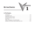
GETTING STARTED
CHAPTER
1
In This Chapter...
Introduction . . . . . . . . . . . . . . . . . . . . . . . . . . . . . . . . . . . . . . . . . . . . . . . . . . . . . . .1–2
Conventions Used
. . . . . . . . . . . . . . . . . . . . . . . . . . . . . . . . . . . . . . . . . . . . . . . . . .1–2
Selecting the Proper Module . . . . . . . . . . . . . . . . . . . . . . . . . . . . . . . . . . . . . . . . . .1–3
Installing the Option Modules . . . . . . . . . . . . . . . . . . . . . . . . . . . . . . . . . . . . . . . . .1–5
Module LED Indicator . . . . . . . . . . . . . . . . . . . . . . . . . . . . . . . . . . . . . . . . . . . . . . . .1–6
Power Budgeting . . . . . . . . . . . . . . . . . . . . . . . . . . . . . . . . . . . . . . . . . . . . . . . . . . .1–6
Chapter 1: Getting Started
Introduction
1
The Purpose of this Manual
This manual will discribe the option modules that are available for the DL05 and DL06 micro
2
PLC families. It will show you how to select and install an option module for your PLC.
Supplemental Manuals
3
You will either need a copy of the DL05 User Manual (D0–USER–M) or the DL06 User
Manual (D0–06USER–M) at hand when incorporating any one of the option modules in
4
your PLC.
Technical Support
5
We strive to make our manuals the best in the industry. We rely on your feedback to let us know
if we are reaching our goal. If you cannot find the solution to your particular application, or, if
6
for any reason you need technical assistance, please call us at:
770–844–4200
7
Our technical support group will work with you to answer your questions. They are available
Monday through Friday from 9:00 A.M. to 6:00 P.M. Eastern Time. We also encourage you to
visit our web site where you can find technical and non-technical information about our
8
products and our company.
http://www.automationdirect.com
9
If you have a comment, question or suggestion about any of our products, services, or manuals,
please fill out and return the ‘Suggestions’ card that was included with this manual.
10
Conventions Used
11
When you see the “notepad” icon in the left-hand margin, the paragraph to its immediate right will be a
special note. The word NOTE: in boldface will mark the beginning of the text.
12
When you see the “exclamation mark” icon in the left-hand margin, the paragraph to its immediate right
13
will be a warning. This information could prevent injury, loss of property, or even death (in extreme
cases). The word WARNING: in boldface will mark the beginning of the text.
14
Key Topics for Each Chapter
The beginning of each chapter will list the key topics
A
that can be found in that chapter.
C
B
1
C
D
Getting Started
HAPTER
In This Chapter...
General Information .................................................................1-2
Specifications ...........................................................................1-4
1–2
DL05/06 Option Modules User Manual; 7th Ed. Rev. A, 08/11
Chapter 1: Getting Started
Selecting the Proper Module
DL05
The DL05 Micro PLC only has one option slot to
install an option module. The proper selection of a
module is dependent on the control application.
DL06
The DL06 Micro PLC has four option slots. The option
modules can also be added according to the control
application.
Module Choices
There are over thirty option modules available. The specifications and wiring diagrams for the
discrete I/O modules can be found in the next chapter. A full description of the analog modules
can be found in their respective chapters in this manual. The memory cartridge module,
D0-01MC, can be found in the DL05 Micro PLC User Manual. The communications and
specialty modules are described in their respective user manuals, see user manual p/n reference
below. The following table lists the modules available.
Discrete Modules
Part Number
Description
F0-08SIM
D0-10ND3
D0-10ND3F
D0-16ND3
F0-08NA-1
D0-10TD1
D0-16TD1
D0-10TD2
D0-16TD2
D0-07CDR
D0-08TR
D0-08CDD1
F0-04TRS
8 point Simulator Input
10 point DC Input
10 point fast DC Input
16 point DC Input
8 point AC Input
10 point DC Output (sinking)
16 point DC Output (sinking)
10 point DC Output (sourcing)
16 point DC Output (sourcing)
4 point DC Input, 3 point Relay Output
8 point Relay Output
4 point DC Input, 4 point DC Output (sinking)
4 point High Current Relay Output
Analog and Specialty module choices can be found on the next page.
DL05/06 Option Modules User Manual; 7th Ed. Rev. A, 08/11
1
2
3
4
5
6
7
8
9
10
11
12
13
14
A
B
C
D
1–3
Chapter 1: Getting Started
Module Choices, continued.
1
2
3
4
5
6
7
8
9
10
11
12
13
14
A
B
C
D
1–4
Analog Modules
Part Number
Description
F0-04AD-1
F0-04AD-2
F0-08ADH-1
F0-08ADH-2
F0-04DAH-1
F0-04DAH-2
F0-08DAH-1
F0-08DAH-2
F0-2AD2DA-2
F0-4AD2DA-1
F0-4AD2DA-2
F0-04RTD
F0-04THM
4-Channel Analog Input, Current
4-Channel Analog Input, Voltage
8-Channel High-Resolution Analog Input, Current
8-Channel High-Resolution Analog Input, Voltage
4-Channel High-Resolution Analog Output, Current
4-Channel High-Resolution Analog Output, Voltage
8-Channel High-Resolution Analog Output, Current
8-Channel High-Resolution Analog Output, Voltage
2-Channel Input/2-Channel Output Analog Combination, Voltage
4-Channel Input/2-Channel Output Analog Combination, Current
4-Channel Input/2-Channel Output Analog Combination, Voltage
4-Channel RTD Input
4-Channel Thermocouple Input
Part Number
Description
D0-01MC
D0-DCM
D0-DEVNETS
H0-ECOM(100)
H0-PSCM
H0-CTRIO
F0-CP128
Memory Cartridge/Real Time Clock (DL05 only) (see User Manual p/n D0-USER-M)
Data Communications Module
DeviceNet Slave (User Manual p/n D0-DEVNETS-M)
10Base-T (10/100Base-T) Ethernet Network (User Manaul p/n HX-ECOM-M)
Profibus Slave Communications (User Manual p/n HX-PSCM-M)
High Speed Counter Interface (User Manual p/n HX-CTRIO-M)
Triple Port Basic CoProcessor (User Manual p/n F0-CP-M)
Specialty Modules
DL05/06 Option Modules User Manual; 7th Ed. Rev. A, 08/11
Chapter 1: Getting Started
Installing the Option Modules
Before installing the option module in the DL05 option slot or the DL06 option slots set the
necessary jumpers and/or dip switches on the module. Refer to the chapter(s) that pertains to
the module(s) being installed.
Remove the Slot Cover
The first step in installing the option module is to remove the protective option slot cover.
Remove the cover by squeezing the pinch tabs and lifting the cover off.
Pinch Tabs
Option Module
Slot Covers
G
LG
Y0 Y2
C1 Y5 Y7 Y10 Y12 C3 Y15 Y17
0V
AC(L) AC(N) 24V C0
Y1
Y3 Y4
Y6 C2
Y11 Y13 Y14 Y16 N.C.
OUTPUT: 6–240V
2.0A PWR: 100–240V 50–60Hz40VA
50 – 60Hz 2.0A, 6 – 27V
Y
0
1
2
3
4
5
6
7
10
11
12 13
14
15 16
17
20
PWR
RUN
CPU
D0–06DR
21 22
TX1
RX1
TX2
23
X
INPUT: 12 – 24V
RX2
3 – 15mA
C0
X1
X0
X2
X3
X4
X6
C2 X11 X13 X14 X16 C4 X21 X23 N.C.
C1
X5
X7 X10 X12 C3 X15 X17 X20 X22 N.C.
TERM
PORT1
PORT2
RUN STOP
Insert the Module
Now, insert the module into the open slot. Locate the module so the printed information is
oriented in the same direction as the markings on the PLC. Be careful to align the female
connector on the printed circuit board of the module with the male connector on the PLC
mother board. Press the module into the slot until the front of the module is flush with the front
of the PLC. Install the remaining modules in the DL06. Once the modules are in place the PLC
is ready to be programmed.
WARNING: Power to the PLCs must be disconnected before inserting or removing a module. Failure to
disconnect power could result in serious damage to a module, the PLC or both.
DL05/06 Option Modules User Manual; 7th Ed. Rev. A, 08/11
1
2
3
4
5
6
7
8
9
10
11
12
13
14
A
B
C
D
1–5
Chapter 1: Getting Started
Module LED Indicator
Most discrete I/O Option modules have an LED indicator. The indicator flickers or stays
1
constant while the CPU is accessing the module, whether in program mode or run mode. It is
not a diagnostics indicator, therefore the on status is not an indication the I/O module is
2
functioning properly.
3 Power Budgeting
The DL06 has four option card slots. To determine whether the combination of cards you select
4
will have sufficient power, you will need to perform a power budget calculation.
Power supplied
5
Power is supplied from two sources, the internal base unit power supply and, if required, an
external supply (customer furnished). The D0-06xx (AC powered) PLCs supply a limited
amount of 24VDC power. The 24VDC output can be used to power external devices. For
6
power budgeting, start by considering the power supplied by the base unit. All DL06 PLCs
supply the same amount of 5VDC power. Only the AC units offer 24VDC auxiliary power. Be
7
aware of the trade-off between 5VDC power and 24VDC power. The amount of 5VDC power
available depends on the amount of 24VDC power being used, and the amount of 24VDC
power available depends on the amount of 5VDC power consumed. Determine the amount of
8
internally supplied power from the table on the following page.
9
Power required by base unit
Because of the different I/O configurations available in the DL06 family, the power consumed
by the base unit itself varies from model to model. Subtract the amount of power required by
10
the base unit from the amount of power supplied by the base unit. Be sure to subtract 5VDC
and 24VDC amounts.
11
Power required by option cards
Next, subtract the amount of power required by the option cards you are planning to use.
12
Again, remember to subtract both 5VDC and 24VDC. If your power budget analysis shows
surplus power available, you should have a workable configuration.
13
14
A
B
C
D
1–6
DL05/06 Option Modules User Manual; 7th Ed. Rev. A, 08/11
Chapter 1: Getting Started
DL06 Power Supplied by Base Units
Part Number
D0-06xx
D0-06xx-D
5 VDC (mA)
24 VDC (mA)
<1500mA
<2000mA
1500mA
300mA
200mA
none
DL05/06 Power Consumed
by Option Cards
Part Number
D0-07CDR
D0-08CDD1
D0-08TR
D0-10ND3
D0-10ND3F
D0-10TD1
D0-10TD2
D0-16ND3
D0-16TD1
D0-16TD2
F0-04TRS
F0-08NA-1
F0-04AD-1
F0-04AD-2
F0-2AD2DA-2
F0-4AD2DA-1
F0-4AD2DA-2
F0-04RTD
F0-04THM
F0-08SIM
F0-08ADH-1
F0-08ADH-2
F0-04DAH-1
F0-08DAH-1
F0-04DAH-2
F0-08DAH-2
D0-01MC
D0-DCM
D0-DEVNETS
H0-PSCM
H0-ECOM
H0-ECOM100
H0-CTRIO
F0-CP128
5 VDC (mA)
130mA
100mA
280mA
35mA
35mA
150mA
150mA
35mA
200mA
200mA
250mA
5mA
50mA
75mA
50mA
100mA
100mA
70mA
30mA
1mA
25mA
25mA
25mA
25mA
25mA
25mA
24 VDC (mA)
none
none
none
none
none
none
none
none
none
none
none
none
none
none
30mA
40mA
none
none
none
none
25mA
25mA
150mA
220mA
25mA
25mA
used only in DL05
250mA
none
45mA
530mA
250mA
300mA
250mA
none
none
none
none
none
150mA
none
DL06 Base Unit Power Required
Part Number
D0-06AA
D0-06AR
D0-06DA
D0-06DD1
D0-06DD2
D0-06DR
D0-06DD1-D
D0-06DD2-D
D0-06DR-D
5 VDC (mA)
24 VDC (mA)
800mA
900mA
800mA
600mA
600mA
950mA
600mA
600mA
950mA
none
none
none
280mA*
none
none
280mA*
none
none
* Auxiliary 24VDC used to power V+ terminal of
D0-06DD1/-D sinking outputs.
DL05/DL06 Power Consumed by Other Devices
Part Number
D0-06LCD
D2-HPP
DV1000
EA1-S3ML
5 VDC (mA)
24 VDC (mA)
50mA
200mA
150mA
210mA
none
none
none
none
Power Budgeting Example
Power Source
D0-06DD1
(select row A
or row B)
A
1500mA
300mA
B
2000mA
200mA
Current Required
D0-06DD1
D0-16ND3
D0-10TD1
D0-08TR
F0-4AD2DA-2
D0-06LCD
Total Used
Remaining
5VDC
24VDC
power (mA) power (mA)
A
B
5VDC
24VDC
power (mA) power (mA)
600mA
35mA
150mA
280mA
100mA
50mA
1215mA
285mA
785mA
280mA*
0
0
0
0
0
280mA
20mA
note 1
NOTE 1: If the PLC’s auxiliary 24VDC power
source is used to power the sinking
outputs, use power choice A, above.
DL05/06 Option Modules User Manual; 7th Ed. Rev. A, 08/11
1
2
3
4
5
6
7
8
9
10
11
12
13
14
A
B
C
D
1–7
DL05/06 Option Modules User Manual; 7th Ed. Rev. A, 08/11