1
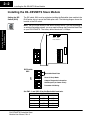
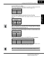
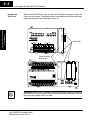
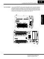
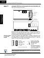
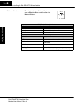
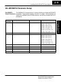
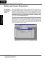
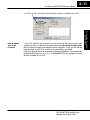
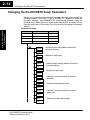
Installing the
DeviceNet Slave
Module
12
In This Chapter. . . .
— Installing the D0–DEVNETS Slave Module
— Configure the Adapter
— D0–DEVNETS Parameter Setup
— Software and Firmware Requirements
— Writing the D0–DEVNETS Setup
2–2
Installing the D0–DEVNETS Slave Module
Installing the D0–DEVNETS Slave Module
Setting the DIP
Switch (SW1)
The DIP switch, SW1 must be set before installing the DeviceNet slave module in the
DL05 option slot or in one of the DL06 option slots. The following diagram shows the
location of the DIP switch.
Installing the DeviceNet
Slave Module
Note: Be sure to look closely at the default settings below. If you are connecting to
an existing DeviceNet network, you may need to change the DeviceNet Baud Rate
on your D0–DEVNETS. The factory default baud rate is 125kbps.
SW2
SW3
Node Address
O
1
F
2
F
3
4
5
6
DIP Switch
SW1
1
DeviceNet Baud Rate
2
OFF
Installation and
Safety Guidelines
SW1
3
Slave I/O Only Mode
4
Adapter Diagnostic Information
5
Hold Outputs (on Comm. Error)
6
Parameter Initializing
Set SW1–1 and SW1–2 for the DeviceNet baud rate.
DeviceNet Baud Rate
Baud Rate
SW1–1
SW1–2
125 kbps
OFF
OFF
250 kbps
ON
OFF
500 kbps
OFF
ON
Reserved
ON
ON
D0–DEVNETS DeviceNet Slave
Module User Manual, Rev A
Installing the D0–DEVNETS Slave Module
2–3
Set the DL05/06 to Slave Mode.
When SW1–3 is ON, the DL05/DL06 can be placed in the RUN mode with the
external RUN/TERM/STOP switch (with or without a program in it).
Slave I/O Only Mode
Mode
SW1–3
Slave I/O only
ON
Normal
OFF
When SW1–4 is OFF D0–DEVNETS adds adapter information to the head of I/O
polling.
Adapter diagnostic
information
Mode
SW1–4
Disable
ON
Enable
OFF
Installing the DeviceNet
Slave Module
Eliminate adapter diagnostic information bits from I/O polling.
Note: Leaving position 4 OFF will add 2 bytes of inputs and 2 bytes of outputs for
diagnostic information at the beginning of your I/O polling. Refer to the Adapter
Input/Output Status Word tables on page C–8.
Position SW1–5 ON will hold the outputs on if there is a communication error.
Hold Outputs
(on Comm. Error)
SW1–5
Turn Off
OFF
Hold
ON
Position SW1–6 ON will initialize the D0–DEVNETS system parameters.
Parameter Initializing
Mode
SW1–6
Description
Initialize 1
ON
Default is set when power is ON *1
Initialize 2
OFF
*1 Initialization parameter value changes with status of DIP switch positions 3 and 6.
Refer to the Initialization Parameter Values table on page D–2.
Note: All DIP switch postions shown are the factory default settings (all OFF).
D0–DEVNETS DeviceNet Slave
Module User Manual, Rev A
Installation and
Safety Guidelines
Outputs
2–4
Installing the D0–DEVNETS Slave Module
When the D0–DEVNETS module is ready to be installed the protective option slot
cover must be removed. The protective cover is removed from the option card slot by
squeezing the pinch tabs and lifting the cover off.
Installing the DeviceNet
Slave Module
Remove the
Slot Cover
Pinch Tabs
Option Module
Slot Covers
G
LG
Y0 Y2
C1 Y5 Y7 Y10 Y12 C3 Y15 Y17
0V
Y1
Y3 Y4
Y6 C2
Y11 Y13 Y14 Y16 N.C.
AC(L) AC(N) 24V C0
OUTPUT: 6–240V
50 – 60Hz 2.0A, 6 – 27V
2.0A PWR: 100–240V 50–60Hz40VA
Y
0
1
2
3
4
5
6
7
10
11
12 13
14
15 16
17
20
PWR
RUN
CPU
D0–06DR
21 22
TX1
RX1
TX2
23
X
Installation and
Safety Guidelines
INPUT: 12 – 24V
RX2
3 – 15mA
C0
X1
X0
X2
X3
X4
X6
C2 X11 X13 X14 X16 C4 X21 X23 N.C.
C1
X5
X7 X10 X12 C3 X15 X17 X20 X22 N.C.
TERM
PORT1
PORT2
RUN STOP
WARNING: Power to the PLC must be disconnected before inserting or removing
the D0–DEVNETS slave module. Failure to disconnect power could result in serious
damage to the module, the PLC or both.
D0–DEVNETS DeviceNet Slave
Module User Manual, Rev A
2–5
Installing the D0–DEVNETS Slave Module
Insert the Module
Insert the D0–DEVNETS slave module into the open card slot. Locate the module so
the printed information is oriented in the same direction as the markings on the PLC.
Be careful to align the female connector on the printed circuit board of the module
with the male connector on the PLC mother board. Press the module into the slot
until the front of the module is flush with the front of the PLC.
Installing the DeviceNet
Slave Module
STATUS
MS
NS
D0–DEVNETS
STATUS
G
LG
Y0 Y2
C1 Y5 Y7 Y10 Y12 C3 Y15 Y17
0V
Y1
Y3 Y4
Y6 C2
Y11 Y13 Y14 Y16 N.C.
AC(L) AC(N) 24V C0
OUTPUT: 6–240V
50 – 60Hz 2.0A, 6 – 27V
2.0A PWR: 100–240V 50–60Hz40VA
Y
0
1
2
3
4
5
6
7
10
11
12 13
14
15 16
17
20
MS
NS
PWR
RUN
CPU
D0–06DR
21 22
TX1
RX1
TX2
23
INPUT: 12 – 24V
RX2
3 – 15mA
D0–DEVNETS
C0
X1
X0
X2
X3
X4
X6
C2 X11 X13 X14 X16 C4 X21 X23 N.C.
C1
X5
X7 X10 X12 C3 X15 X17 X20 X22 N.C.
TERM
PORT1
PORT2
RUN STOP
D0–DEVNETS DeviceNet Slave
Module User Manual, Rev A
Installation and
Safety Guidelines
X
2–6
Installing the D0–DEVNETS Slave Module
Set the Node
Address
Once the D0–DEVNETS is installed in the option slot, set the Node Address. The
Node Address rotary switches are accessed by removing the cover located to the
right of Port1 and Port2 on the DL05.
RUN
STOP
TERM
Node Address
PORT1
PORT2
Installing the DeviceNet
Slave Module
SW3 X10
SW2 X1
Node Address
Rotary Switches
Installation and
Safety Guidelines
Remove the cover associated with the option slot where the D0–DEVNETS is
installed in for the DL06 Once the access cover is removed, use a small, flat,
screwdriver to set the Node Address to an available address (or MAC ID), from 0 –
63. Note that SW3 sets the tens and SW2 sets the units.
Wiring the Adapter Connect the DeviceNet cable (Belden 3085A, YR–29832 or equivalent) to the
removable connector as shown below. The wire colors are also labeled on the front
to a DeviceNet
of the adapter. Be sure to connect a terminating resistor (121 Ohm 1%, 1/4W). An
Network
external 11–25 VDC power supply is also required.
V+ (red)
CAN* High (white)
Shield (bare)
CAN* Low (blue)
V– (black)
* Controller Area Network (CAN)
Connect a terminating
resistor across the CAN
High (white) and CAN
Low (blue) screw
terminals.
The terminating resistor is
121 Ohm 1%, 1/4 Watt. (2
resistors are included with
each D0–DEVNETS).
Tip: Be sure that each end of the DeviceNet network ’trunk” has a proper terminating
resistor connected as shown above.
D0–DEVNETS DeviceNet Slave
Module User Manual, Rev A
Installing the D0–DEVNETS Slave Module
2–7
Configure the Adapter
Installation and
Safety Guidelines
D0–DEVNETS DeviceNet Slave
Module User Manual, Rev A
Installing the DeviceNet
Slave Module
Use the software of your DeviceNet master to configure the controller for your
Configuring the
DeviceNet Adapter network. Refer to the software Help file and/or manual for help with configuration.
Follow these basic steps when configuring your D0–DEVNETS adapter.
1. Set the Adapter Node Address:
In the DeviceNet master software, make sure the adapter node address is
set to an available node number on the DeviceNet network (from 0 to 63).
2. Add the EDS file (if required by the software):
In your DeviceNet software, add the D0–DEVNETS Electronic Data Sheet
(EDS) file from the disk which came with this manual or from our web site
www.automationdirect.com. Some software may not provide for the use
of EDS files.
3. Commission the Node:
Use the DeviceNet software to “Commission the Node” of the adapter.
Again, some software may not require this.
4. Add the D0–DEVNETS to the Scan List:
Add the D0–DEVNETS to the Scan List in your DeviceNet Master software.
5. Set the Input/Output Bytes:
If required by your DeviceNet software, set the I/O Parameters to Tx =
Output bytes and Rx = Input bytes, for Polled I/O. Follow the steps in
Appendix G to determine the actual number of Output and Input bytes your
system has.
6. Map the I/O to the Master:
Map the D0–DEVNETS I/O to the Scanner using Auto Map, or map the I/O
to another location if desired.
7. Scan:
Go Online (or Scan) to verify the configuration and check for errors.
8. View Indicators on the adapter:
Refer to the Status Indicators when connecting to the network.
2–8
Installing the D0–DEVNETS Slave Module
Status Indicators
The adapter has two Status Indicators,
one for Module Status and the other for
Network Status.
STATUS
MS
NS
Indication
Status
OFF
No power to module.
Solid Green
Power is ON, normal condition
Solid Red
Critical module Failure
NS (Network Status) Indicator
Indication
Status
OFF
No power to module or no Network Access
Flashing Green
Online but not connected (no connection
established)
Solid Green
Online, link okay and connected
Flashing Red
Recoverable fault
Solid Red
Critical module Failure (Duplicate ID or Bus off)
Installation and
Safety Guidelines
Installing the DeviceNet
Slave Module
MS (Module Status) Indicator
D0–DEVNETS DeviceNet Slave
Module User Manual, Rev A
Installing the D0–DEVNETS Slave Module
2–9
D0–DEVNETS Parameter Setup
The DL05/06 PLCs reserve several V–memory locations for storing the DEVNETS
D0–DEVNETS
Default Parameters parameters. These special registers store the I/O ranges. The parameters are
stored in the DL05/06 systems FLASH memory, and are not lost when the PLC is
powered off.
V7610
Description of Contents
Input starting address
Factory Default Value
V40400
Range
V40400 – 40417 (X0–377)
V40500 – 40517 (Y0–377)
V40600 – 40637 (C0–777)
V41000 – 41017 (S0 – 377)
V41100 – 41107 (T0 – 177)
V41140 – 41147 (CT0 – 177)
V41200 – 41237 (SP0 – 777)
V7611
Input number of bytes
2 Bytes
0 – 8 Bytes
V7612
Output starting address
V40500
V40400 – 40417 (X0 – 377)
Installing the DeviceNet
Slave Module
System
V-memory
V40500 – 40517 (Y0–377)
V40600 – 40637 (C0–777)
V41000 – 41017 (S0–377)
V41100 – 41107 (T0 – 177)
V41140 – 41147 (CT0 – 177)
V41200 – 41237 (SP0 – 777)
Output number of bytes
2 Bytes
0 – 8 Bytes
V7614
Input starting V–memory location
V3000
V0 – 7777
V7615
Input V–memory number of bytes
58 Bytes
0 – 128 Bytes
V7616
Output starting V–memory location
V3100
V0 – 7377
V7617
Output V–memory number of bytes
52 Bytes
0 – 128 Bytes
D0–DEVNETS DeviceNet Slave
Module User Manual, Rev A
Installation and
Safety Guidelines
V7613
2–10
Installing the D0–DEVNETS Slave Module
Software and Firmware Requirements
When a D0–DEVNETS module is installed, the DL05/06 PLCs do not need to have a
relay ladder logic (RLL) program in them to operate as slave I/O. However, if you are
using the D0–DEVNETS in either a DL05 or a DL06 for local control on a network,
they must have a RLL control program in them. You will need DirectSOFT32 Version
3.0b (or later) for the DL05 and/or Version 4.0 for DL06 in order to use all features of
the D0–DEVNETS. If you have a licensed copy of Version 3.0 or 3.0a, the Version
3.0b Maintenance Release (or a later maintenance release) is available for free on
our website at www.automationdirect.com.
The DL05 must have Version 3.0 (or later) firmware and the DL06 must have Version
1.0 (or later) firmware to operate correctly with all features of the D0–DEVNETS. If
your DL05/06 was received with your D0–DEVNETS, the correct firmware is already
installed in the PLC. If you already have a DL05 and need to determine what
firmware version is installed in the PLC, connect to the DL05 with DirectSOFT32
programming software, and click on PLC/Diagnostics/System Information. This will
bring up the System Information screen.
Installation and
Safety Guidelines
Installing the DeviceNet
Slave Module
How to Update
Your DirectSOFT32
Programming
Software
D0–DEVNETS DeviceNet Slave
Module User Manual, Rev A
Installing the D0–DEVNETS Slave Module
2–11
The “CPU Version:” will tell you what firmware version is installed in your PLC.
If your PLC requires new firmware, you may download the latest firmware and
upgrade tool from our website. Point your browser to www.automationdirect.com,
click on technical support, then select Firmware Upgrades. There, you will find the
latest firmware for your CPU, which you can download at no charge.
Follow the upgrade instructions contained in the downloaded files. Cycle power after
upgrading the firmware in your PLC, and DirectSOFT32 will recognize the new
features available for the PLC.
Installing the DeviceNet
Slave Module
How to Update
Your DL05
Firmware
Installation and
Safety Guidelines
D0–DEVNETS DeviceNet Slave
Module User Manual, Rev A
2–12
Installing the D0–DEVNETS Slave Module
Changing the D0–DEVNETS Setup Parameters
There may be a time when the initial setup parameters will need to be changed. The
following example shows how to edit a DL05/06 PLC program to make the
parameter changes using DirectSOFT32 programming software. Once the
following rung is editted, be sure to either power cycle the PLC or put the PLC into
Program mode, then to Run mode. This will insure that the settings will become
effective.
Installing the DeviceNet
Slave Module
Parameter Example
Function
Register Number
Data Size
Input Point
V40400
2 Bytes
Output Point
V40500
2 Bytes
Input Register
V3000
128 Bytes
Output Register V3100
128 Bytes
SP0
LDA
O40400
Load the input starting address and store it
to system memory
OUT
V7610
LD
K2
Number of input bytes.
OUT
V7611
LDA
O40500
OUT
V7612
LD
K2
Load the output starting address and store it
to system memory.
Number of output bytes.
Installation and
Safety Guidelines
OUT
V7613
LDA
O3000
OUT
V7614
LD
K128
Load the V–memory location to store the
input data.
Number of input register bytes.
OUT
V7615
LDA
O3100
OUT
V7616
LD
K128
OUT
V7617
D0–DEVNETS DeviceNet Slave
Module User Manual, Rev A
Load the V–memory location to store the
output data.
Number of output register bytes.