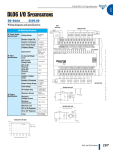
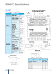
1
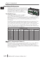
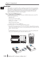
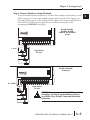
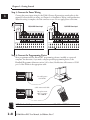
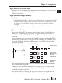
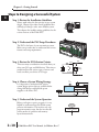
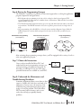
GETTING STARTED
CHAPTER
1
In This Chapter...
Introduction . . . . . . . . . . . . . . . . . . . . . . . . . . . . . . . . . . . . . . . . . . .1–2
Conventions Used . . . . . . . . . . . . . . . . . . . . . . . . . . . . . . . . . . . . . .1–3
DL06 Micro PLC Overview . . . . . . . . . . . . . . . . . . . . . . . . . . . . . . . .1–4
I/O Quick Selection Guide . . . . . . . . . . . . . . . . . . . . . . . . . . . . . . . .1–5
Quick Start . . . . . . . . . . . . . . . . . . . . . . . . . . . . . . . . . . . . . . . . . . . .1–6
Steps to Designing a Successful System . . . . . . . . . . . . . . . . . . . . .1–10
Questions and Answers about DL06 Micro PLCs . . . . . . . . . . . . . .1–12
Chapter 1: Getting Started
1
2
3
4
5
6
7
8
9
10
11
12
13
14
A
B
C
D
Introduction
The Purpose of this Manual
Thank you for purchasing a DL06 Micro PLC. This manual shows you how to install,
program, and maintain all PLCs in the DL06 family. It also helps you understand how to
interface them to other devices in a control system.This manual contains important
information for personnel who will install DL06 PLCs and for the PLC programmer. This
user manual will provide the information you need to get and keep your system up and
running.
Supplemental Manuals
The D0–OPTIONS–M manual contains technical information about the option cards
available for the DL06 PLCs. This information includes specifications and wiring diagrams
that will be indispensable if you use any of the optional I/O or communications cards. If you
have purchased one of our operator interface panels or DirectSOFT™ programming
software, you will want to refer to the manuals that are written for these products.
Technical Support
We strive to make our manuals the best in the industry. We rely on your feedback to let us
know if we are reaching our goal. If you cannot find the solution to your particular
application, or, if for any reason you need technical assistance, please call us at
770–844–4200
Our technical support group will work with you to answer your questions. They are available
Monday through Friday from 9:00 A.M. to 6:00 P.M. Eastern Time. We also encourage you
to visit our web site where you can find technical and non-technical information about our
products and our company.
http://www.automationdirect.com
If you have a comment, question or suggestion about any of our products, services, or
manuals, please fill out and return the Suggestions card included with this manual.
1–2
DL06 Micro PLC User Manual, 3rd Edition, Rev. C
Chapter 1: Getting Started
Conventions Used
When you see the notepad icon in the left-hand margin, the paragraph to its
immediate right will be a special note. Notes represent information that may make
your work quicker or more efficient.
The word NOTE in boldface type will mark the beginning of the text.
When you see the exclamation point icon in the left-hand margin, the paragraph to its
immediate right will be a warning. This information could prevent injury, loss of
property, or even death in extreme cases. Any warning in this manual should be
regarded as critical information that should be read in its entirety.
The word WARNING in boldface type will mark the beginning of the text.
Key Topics for Each Chapter
The beginning of each chapter will list the key topics
that can be found in that chapter.
Getting Started
1
CHAPTER
In This Chapter...
General Information .................................................................1-2
Specifications ...........................................................................1-4
1
2
3
4
5
6
7
8
9
10
11
12
13
14
A
B
C
D
DL06 Micro PLC User Manual, 3rd Edition, Rev. C
1–3
Chapter 1: Getting Started
1
2
3
4
5
6
7
8
9
10
11
12
13
14
A
B
C
D
DL06 Micro PLC Overview
The DL06 micro PLC family is a versatile product line that
combines powerful features and a very compact footprint.
The DL06 PLCs offer expandable I/O, high-speed counter,
floating point, PID, etc. There are a number of
communication options and an optional LCD display.
The DL06 PLC Features
The DL06 Micro PLC family includes nine different
versions. All have the same appearance and CPU
performance. The CPU offers an instruction set very similar to our powerful new DL260
CPU including new easy to use ASCII and MODBUS instructions. All DL06 PLCs have two
built-in communications ports that can be used for programming, operator interface,
networking, etc.
Units with DC inputs have selectable high-speed input features on four input points. Units
with DC outputs offer selectable pulse output capability on the first and second output
points. Details of these features and more are covered in Chapter 3, CPU Specifications and
Operation. There are nine versions of the DL06 PLC. The most common industrial I/O
types and power supply voltages are available. Consult the following table to find the model
number of the PLC that best fits your application.
DL06 Micro PLC Family
DL06 Part
Number
D0–06AA
D0–06AR
D0–06DA
D0–06DD1
D0–06DD2
D0–06DR
D0–06DD1–D
D0–06DD2–D
D0–06DR–D
Discrete Input Discrete Output External Power
Type
Type
AC
AC
DC
DC
DC
DC
DC
DC
DC
AC
Relay
AC
DC Sinking
DC Sourcing
Relay
DC Sinking
DC Sourcing
Relay
95–240 VAC
95–240 VAC
95–240 VAC
95–240 VAC
95–240 VAC
95–240 VAC
12–24 VDC
12–24 VDC
12–24 VDC
High-Speed
Input
Pulse Output
No
No
Yes
Yes
Yes
Yes
Yes
Yes
Yes
No
No
No
Yes
Yes
No
Yes
Yes
No
DirectSOFT 5 Programming for Windows™
The DL06 Micro PLC can be programmed with DirectSOFT 5, Ver. 5 or later, a Windowsbased software package that supports familiar features such as cut-and-paste between
applications, point-and-click editing, viewing and editing multiple application programs at
the same time, floating views, intelligent boxes, etc. Firmware version 2.10 is needed in order
to use the intelligent boxes.
1–4
DL06 Micro PLC User Manual, 3rd Edition, Rev. C
Chapter 1: Getting Started
DirectSOFT 5 (part number PC-DSOFT5) supports the DirectLOGIC CPU families. You
can use DirectSOFT 5 to program the DL05, DL06, DL105, DL205, DL305, and DL405
CPUs. A separate manual discusses DirectSOFT 5 programming software. Earlier
programming software versions such as DirectSOFT32, version 4.0 can also be used to
program the DL06.
Handheld Programmer
All DL06 Micro PLCs have a built-in programming port for use with the handheld
programmer (D2–HPP), the same programmer used with the DL05, DL105 and DL205
families. The handheld programmer can be used to create, modify and debug your
application program. A separate manual discusses the Handheld Programmer. Only
D2–HPPs with firmware version 2.0 or later will program the DL06.
NOTE: Not all instructions are available to use with the HPP - the real number instructions, for
example. DirectSOFT will be needed to program instructions such as these.
I/O Quick Selection Guide
The nine versions of the DL06 have input/output circuits which can interface to a wide
variety of field devices. In several instances a particular input or output circuit can interface to
either DC or AC voltages, or both sinking and sourcing circuit arrangements. Check this
guide to find the proper DL06 Micro PLC to interface to the field devices in your application.
I/O Selection Guide
DL06 Part
Number
INPUTS
I/O type/
commons Sink/Source
Voltage
Ranges
OUTPUTS
I/O type/ Sink/Source Voltage/ Current Ratings*
commons
D0–06AA
AC / 5
–
90 – 120 VAC
AC / 4
D0–06AR
AC / 5
–
90 – 120 VAC
Relay / 4
D0–06DA
DC / 5
Sink or Source
12 – 24 VDC
AC / 4
D0–06DD1
DC / 5
Sink or Source
12 – 24 VDC
DC / 4
D0–06DD2
DC / 5
Sink or Source
12 – 24 VDC
DC / 4
D0–06DR
DC / 5
Sink or Source
12 – 24 VDC
Relay / 4
D0–06DD1–D
DC / 5
Sink or Source
12 – 24 VDC
DC / 4
D0–06DD2–D
DC / 5
Sink or Source
12 – 24 VDC
DC / 4
D0–06DR–D
DC / 5
Sink or Source
12 – 24 VDC
Relay / 4
–
17 – 240 VAC, 50/60 Hz 0.5A
2A
Sink or Source 66 –– 27VDC,
240 VAC, 2A
–
17 – 240 VAC, 50/60 Hz 0.5A
6 – 27 VDC, 0.5A (Y0–Y1)
Sink
6 – 27 VDC, 1.0A (Y2–Y17)
12 – 24 VDC, 0.5A (Y0–Y1)
Source
12 – 24 VDC, 1.0A (Y2–Y17)
2A
Sink or Source 66 –– 27VDC,
240 VAC, 2A
6 – 27 VDC, 0.5A (Y0–Y1)
Sink
6 – 27 VDC, 1.0A (Y2–Y17)
12 – 24 VDC, 0.5A (Y0–Y1)
Source
12 – 24 VDC, 1.0A (Y2–Y17)
VDC, 2A
Sink or Source 66 –– 27
240 VAC, 2A
* See Chapter 2, Specifications for more information about a particular DL06 version.
DL06 Micro PLC User Manual, 3rd Edition, Rev. C
1–5
1
2
3
4
5
6
7
8
9
10
11
12
13
14
A
B
C
D
Chapter 1: Getting Started
1
2
3
4
5
6
7
8
9
10
11
12
13
14
A
B
C
D
Quick Start
This example is not intended to tell you everything you need to know about programming
and starting up a complex control system. It is only intended to give you an opportunity to
demonstrate to yourself and others the basic steps necessary to power up the PLC and
confirm its operation. Please look for warnings and notes throughout this manual for
important information you will not want to overlook.
Step 1: Unpack the DL06 Equipment
Unpack the DL06 and gather the parts necessary to build this demonstration system. The
recommended components are:
• DL06 Micro PLC
• AC power cord or DC power supply
• Toggle switches (see Step 2 on next page)
• Hook-up wire, 16-22 AWG
• DL06 User Manual (this manual)
• A small screwdriver, 5/8” flat or #1 Philips type
You will need at least one of the following programming options:
• DirectSOFT 5 Programming Software V5.0 or later (PC-DSOFT5), DirectSOFT 5 Programming
Software Manual (included with the software), and a programming cable (D2-DSCBL connects the
DL06 to a personal computer).
or
• D2-HPP Handheld Programmer, firmware version 2.0 or later, (comes with programming cable).
Please purchase Handheld Programmer Manual D2-HPP-M separately.
G
LG
Y0
Y2
C1
Y5
Y7 Y10 Y12
C3 Y15 Y17
0V
AC(L) AC(N) 24V C0
Y1
Y3
Y4
Y6
C2
Y11 Y13 Y14 Y16 N.C.
OUTPUT: 6-240V
Y
X
0
1
2
INPUT: 12 - 24V
50 - 60Hz
3
LOGIC
C0
4
3 - 15mA
X0
5
06
2.0A, 6 - 27V
6
7
10
2.0A
11
12
PWR: 100-240V
13
14
15
16
PWR
RUN
CPU
TX1
RX1
TX2
RX2
D0-06DR
50-60Hz 40VA
17
20
21 22
23
K oyo
X1
X2
X3
C1
X4
X5
X6
X7
C2 X11 X13 X14 X16 C4 X21 X23 N.C.
X10 X12 C3
X15 X17 X20 X22 N.C.
TERM
PORT1
1–6
PORT2
RUN STOP
DL06 Micro PLC User Manual, 3rd Edition, Rev. C
Chapter 1: Getting Started
fuse
L L L L
L L L L
L L L L
+
L L L L
+24 VDC
Step 2: Connect Switches to Input Terminals
To proceed with this quick-start exercise or to follow other examples in this manual, you will
need to connect one or more input switches as shown below. If you have DC inputs on an
AC-supply DL06, you can use the auxiliary 24VDC supply on the output terminal block or
other external 12-24VDC power supply. Be sure to follow the instructions in the
Y
D0-06DD1
accompanying
WARNING on this page.
X
G
LG
0V
Y0
Y2
C1
Y5
Y7 Y10 Y12
C3 Y15 Y17
AC(L) AC(N) 24V C0
Y1
Y3
Y4
Y6
C2
Y11 Y13 Y14 Y16 +V
OUTPUT: Sinking Output
0
1
2
3
INPUT: 12 - 24V
1.0A
5
6
7
PWR: 100-240V
10
11
12
13
50-60Hz 40VA
14
15
16
17
20
21 22
23
3 - 15mA
LOGIC
C0
D0-06DA, D0-06DD1,
D0-06DD2, D0-06DR,
D0-DD1-D, and D0-06DR1-D
DC Input
06
K oyo
X1
X0
12 - 24 VDC
6 - 27V
4
X3
X2
X4
X6
X5
C1
X7
C2 X11 X13 X14 X16 C4 X21 X23 N.C.
X15 X17 X20 X22 N.C.
X10 X12 C3
fuse
+
Toggle Switches
UL Listed
0V
Y0
Y2
C1
Y5
Y7 Y10 Y12
C3 Y15 Y17
G
LG
AC(L) AC(N) 24V C0
Y1
Y3
Y4
Y6
C2
Y11 Y13 Y14 Y16 N.C.
OUTPUT: 17-240V
Y
X
0
1
2
INPUT: 90 - 120V
50 - 60Hz
3
X0
5
7 - 15mA
LOGIC
C0
4
06
0.5A
6
PWR: 100-240V
7
10
11
12
13
50-60Hz 40VA
14
15
16
17
20
D0-06AA
21 22
23
D0-06AA and D0-06AR
AC input only
K oyo
X1
X2
X3
C1
X4
X5
X6
X7
C2 X11 X13 X14 X16 C4 X21 X23 N.C.
X15 X17 X20 X22 N.C.
X10 X12 C3
fuse
90 - 120 VAC
Toggle Switches
UL Listed
WARNING: Remove power and unplug the DL06 when wiring
the switches. Use only UL-approved switches rated for at
least 250VAC, 1A for AC inputs. Firmly mount the switches
before using.
DL06 Micro PLC User Manual, 3rd Edition, Rev. C
1–7
1
2
3
4
5
6
7
8
9
10
11
12
13
14
A
B
C
D
Chapter 1: Getting Started
Step 3: Connect the Power Wiring
1
2
3
4
5
6
7
8
9
10
11
Connect the power input wiring for the DL06. Observe all precautions stated earlier in this
manual. For more details on wiring, see Chapter 2 on Installation, Wiring, and Specifications.
When the wiring is complete, close the connector covers.
Do not apply power at this time.
12 - 24 VDC
-
+
110/220 VAC Power Input
12/24 VDC Power Input
G
LG
0V
Y0
Y2
C1
Y5
Y7 Y10 Y12
C3 Y15 Y17
Y2
C1
Y5
Y7 Y10 Y12
C3 Y15 Y17
G
LG
N.C. Y0
AC(L) AC(N) 24V C0
Y1
Y3
Y4
Y6
C2
Y11 Y13 Y14 Y16 + N.C.Y1
Y3
Y4
Y6
C2
Y11 Y13 Y14 Y16 +V
N.C. C0
50 - 60Hz 0.5A
PWR: 100-240V
50-60Hz 40VA OUTPUT: Sinking Output 6 - 27V
1.0A
PWR: 12-24
20W
OUTPUT: 17-240V
Y
0
X
1
2
3
INPUT: 90 - 120V
4
5
6
7
10
11
12
13
14
15
16
17
7 - 15mA
Y
D0-06AA
200 211 222
X
INPUT: 12 - 24V
06
233
4
5
6
7
10
11
12
13
14
15
17
20
D0-06DD
21 22
23
3 - 15mA
06
Step 4: Connect the Programming Device
16
Most LOGIC
programmers will use DirectSOFT programming
software, installed on a personal
LOGIC
K oyo
K oyo
computer. An
alternative, if you need a compact portable programming
device, is the
Handheld
Programmer
(firmware
version
2.20
or
later).
Both
devices
will
connect
to COM
C0
X1
X3
X4
X6
C2 X11 X13 X14 X16 C4 X21 X23C0N.C.X1
X3
X4
X6
C2 X11 X13 X14 X16 C4 X21 X23 N.C.
X0
X15 X17 X20 X22 N.C.X0
X2
C1 via
X5 the
X7 appropriate
X10 X12 C3 cable.
port 1 of the
DL06
X15 X17 X20 X22 N.C.
X2
C1
X5
X7 X10 X12 C3
12
13
14
A
B
C
D
0V
LG
Y0
Y2
C1
Y5
Y7 Y10 Y12
C3 Y15 Y17
G
AC(L) AC(N) 24V C0
Y1
Y3
Y4
Y6
C2
Y11 Y13 Y14 Y16 N.C.
OUTPUT: 6-240V
50 - 60Hz
2.0A, 6 - 27V
2.0A
PWR: 100-240V
PWR
RUN
CPU
TX1
RX1
TX2
RX2
50-60Hz 40VA
D0-06DR
Y
0
1
2
3
4
5
6
7
10
11
12
13
14
15
16
17
20
21 22
23
X
INPUT: 12 - 24V
3 - 15mA
LOGIC
06
fuse
K oyo
C0
X1
X0
X3
X2
X4
C1
X6
X5
X7
C2 X11 X13 X14 X16 C4 X21 X23 N.C.
X15 X17 X20 X22 N.C.
X10 X12 C3
TERM
PORT1
PORT2
RUN STOP
Use cable part #
D2–DSCBL
DC
Supply
(cable comes with HPP)
0V
LG
Y0
Y2
C1
Y5
Y7 Y10 Y12
C3 Y15 Y17
G
Y1
Y3
Y4
Y6
C2
Y11 Y13 Y14 Y16 N.C.
AC(L) AC(N) 24V C0
OUTPUT: 6-240V
50 - 60Hz
2.0A, 6 - 27V
2.0A
PWR: 100-240V
PWR
RUN
CPU
TX1
RX1
TX2
RX2
50-60Hz 40VA
D0-06DR
Y
0
1
2
3
4
5
6
7
10
11
12
13
14
15
16
17
20
21 22
23
X
INPUT: 12 - 24V
3 - 15mA
LOGIC
06
K oyo
C0
X1
X0
X3
X2
X4
C1
X6
X5
X7
C2 X11 X13 X14 X16 C4 X21 X23 N.C.
X10 X12 C3
X15 X17 X20 X22 N.C.
TERM
PORT1
PORT2
For replacement
cable, use part #
DV–1000CBL
RUN STOP
NOTE: The Handheld Programmer cannot create or access LCD, ASCII or MODBUS instructions.
1–8
DL06 Micro PLC User Manual, 3rd Edition, Rev. C
Chapter 1: Getting Started
Step 5: Switch on the System Power
Apply power to the system and ensure the PWR indicator on the DL06 is on. If not, remove
power from the system and check all wiring and refer to the troubleshooting section in
Chapter 9 for assistance.
Step 6: Initialize Scratchpad Memory
It’s a good precaution to always clear the system memory (scratchpad memory) on a new
DL06. There are two ways to clear the system memory:
• In DirectSOFT, select the PLC menu, then Setup and Initialize Scratch Pad. Initializing Scratch Pad
will return secondary comm port settings and retentive range settings to default. If you have made
any changes to these, you will need to note these changes and re-enter them after initializing
Scratchpad.
• For the Handheld Programmer, use the AUX key and execute AUX 54.
See the Handheld Programmer Manual for additional information.
Step 7: Enter a Ladder Program
At this point, DirectSOFT 5 programmers need to refer to Chapter 2 (Quick Start) in the
DirectSOFT 5 Programming Software Manual. There you will learn how to establish a
communications link with the DL06 PLC, change CPU modes to Run or Program, and enter
a program.
If you are learning how to program with the Handheld Programmer, make sure the CPU is in
Program Mode (the RUN LED on the front of the DL06 should be off ). If the RUN LED is
on, use the MODE key on the Handheld Programmer to put the PLC in Program Mode,
then switch to TERM.
Enter the following keystrokes on the Handheld Programmer.
Equivalent Direct SOFT display
X0
Y0
OUT
CLR
C
2
NEXT
Clear the Program
CLR
E
$
4
AUX
ENT
A
STR
0
ENT
ENT
END
GX
OUT
SHFT
A
E
4
0
N
TMR
3
Move to the first
address and enter
X0 contact
Enter output Y0
ENT
D
CLR
ENT
Enter the END
statement
After entering the simple example program, put the PLC in Run mode by using the Mode
key on the Handheld Programmer.
The RUN indicator on the PLC will illuminate, indicating the CPU has entered the Run
mode. If not, repeat this step, ensuring the program is entered properly or refer to the
troubleshooting guide in chapter 9.
After the CPU enters the run mode, the output status indicator for Y0 should follow the
switch status on input channel X0. When the switch is on, the output will be on.
DL06 Micro PLC User Manual, 3rd Edition, Rev. C
1–9
1
2
3
4
5
6
7
8
9
10
11
12
13
14
A
B
C
D
Chapter 1: Getting Started
Steps to Designing a Successful System
1
2
3
4
5
Step 1: Review the Installation Guidelines
Always make safety the first priority in any system
design. Chapter 2 provides several guidelines that
will help you design a safer, more reliable system.
This chapter also includes wiring guidelines for the
various versions of the DL06 PLC.
Step 2: Understand the PLC Setup Procedures
6
7
The PLC is the heart of your automation system.
Make sure you take time to understand the various
features and setup requirements.
8
9
Step 3: Review the I/O Selection Criteria
There are many considerations involved when you
select your I/O type and field devices. Take time to
understand how the various types of sensors and
loads can affect your choice of I/O type.
10
11
12
13
14
A
B
C
D
+
Input
Sensing
–
Common
Step 4: Choose a System Wiring Strategy
It is important to understand the various
system design options that are available before
wiring field devices and field-side power
supplies to the Micro PLC.
PLC
Input
AC
Power
Loads
DL06
PLC
Power Input
+24 VDC
+
16 Outputs
Commons
20 Inputs
Commons
–
Step 5: Understand the System Operation
Before you begin to enter a program, it is very
helpful to understand how the DL06 system
processes information. This involves not only
program execution steps, but also involves the
various modes of operation and memory
layout characteristics.
1–10
DL06 Micro PLC User Manual, 3rd Edition, Rev. C
Power Up
Initialize Hardware
Chapter 1: Getting Started
Step 6: Review the Programming Concepts
The DL06 PLC instruction set provides for three main approaches to solving the application
program, depicted in the figure below.
• RLL diagram-style programming is the best tool for solving boolean logic and general CPU
register/accumulator manipulation. It includes dozens of instructions, which will also be needed to
augment drums and stages.
• The Timer/Event Drum Sequencer features up to 16 steps and offers both time and/or event-based
step transitions. The DRUM instruction is best for a repetitive process based on a single series of
steps.
• Stage programming (also called RLLPLUS) is based on state-transition diagrams. Stages divide the
ladder program into sections which correspond to the states in a flow chart you draw for your
process.
Standard RLL Programming
(see Chapter 5)
X0
Timer/Event Drum Sequencer
(see Chapter 6)
Stage Programming
(see Chapter 7)
Push–UP
LIGHT
DOWN
CMPD
K309482
SP62
RAISE
LDD
V1076
Y0
OUT
UP
Push–
DOWN
LOWER
After reviewing the programming concepts above, you’ll be equipped with a variety of tools to
write your application program.
Step 7: Choose the Instructions
Once you have installed the Micro PLC and
understand the main programming concepts, you
can begin writing your application program. At
that time you will begin to use one of the most
powerful instruction sets available in a small PLC.
TMR
T1
K30
CNT
CT3
K10
Step 8: Understand the Maintenance and
Troubleshooting Procedures
Sometimes equipment failures occur when we least
expect it. Switches fail, loads short and need to be
replaced, etc. In most cases, the majority of the
troubleshooting and maintenance time is spent
trying to locate the problem. The DL06 Micro
PLC has many built-in features, such as error
codes, that can help you quickly identify
problems.
DL06 Micro PLC User Manual, 3rd Edition, Rev. C
1–11
1
2
3
4
5
6
7
8
9
10
11
12
13
14
A
B
C
D
Chapter 1: Getting Started
1
2
3
4
5
6
7
8
9
10
11
12
13
14
A
B
C
D
Questions and Answers about DL06 Micro PLCs
Q. What is the instruction set like?
A. The instruction set is very close to that of our DL260 CPU. The DL06 instructions
include the drum sequencing instruction, networking, ASCII, MODBUS, LCD,
intelligent boxes and High-Speed I/O capabilities. High-Speed inputs are available on
units with DC inputs only; high-speed outputs are available on units with DC outputs
only.
Q. Do I have to buy the full DirectSOFT 5 programming package to program
the DL06?
A. Yes. The part number for DirectSOFT 5 (PC-DSOFT5) is now used for all PLCs in the
DirectLOGIC family, and the price is very affordable.
Q. Is the DL06 expandable?
A. Yes, the DL06 series function as stand-alone PLCs. However, option card slots allow you
to expand the system without changing the footprint.
Q. Does the DL06 have motion control capability?
A. Yes, the DL06 has limited motion control capabilities. The High-Speed I/O features offer
either encoder inputs with high-speed counting and presets with interrupt, or a
pulse/direction output for stepper control. Three types of motion profiles are available,
which are explained in Appendix E. The H0-CTRIO(2) option module can also be used
to provide more motion functionality.
Q. Are the ladder programs stored in a removable EEPROM?
A. No. The DL06 contains a non-removable FLASH memory for program storage, which
may be written and erased thousands of times. You may transfer programs to/from
DirectSOFT on a PC.
Q. Does the DL06 contain fuses for its outputs?
A. There are no output circuit fuses. Therefore, we recommend fusing each channel, or fusing
each common. See Chapter 2 for I/O wiring guidelines.
Q. Is the DL06 Micro PLC U.L. approved?
A. The Micro PLC has met the requirements of UL (Underwriters’ Laboratories, Inc.), and
CUL (Canadian Underwriters’ Laboratories, Inc.). See our website,
www.Automationdirect.com, for complete details.
Q. Does the DL06 Micro PLC comply with European Union (EU) Directives?
1–12
A. The Micro PLC has met the requirements of the European Union Directives (CE). See our
website, www.Automationdirect.com, for complete details.
DL06 Micro PLC User Manual, 3rd Edition, Rev. C
Chapter 1: Getting Started
Q. Which devices can I connect to the communication ports of the DL06?
A. Port 1: The port is RS-232C, fixed at 9600 baud, odd parity, address 1, and uses the
proprietary K-sequence protocol. The DL06 can also connect to MODBUS RTU and
DirectNET networks as a slave device through port 1. The port communicates with the
following devices:
• DV-1000 Data Access Unit, C-more, DirectTouch, LookoutDirect, DSData or Optimation
Operator interface panels
• DirectSOFT (running on a personal computer)
• D2-HPP handheld programmer
• Other devices which communicate via K-sequence, Directnet, MODBUS RTU protocols should
work with the DL06 Micro PLC. Contact the vendor for details.
A. Port 2: This is a multi-function port. It supports RS-232C, RS422, or RS485, with
selective baud rates (300 - 38,400 bps), address and parity. It also supports the proprietary
K-sequence protocol as well as DirectNet and MODBUS RTU, ASCII In/Out and
non-sequence/print protocols.
Q. Can the DL06 accept 5VDC inputs?
A. No. 5 volts is lower than the DC input ON threshold. However, many TTL logic circuits
can drive the inputs if they are wired as open collector (sinking) inputs. See Chapter 2 for I/O
wiring guidelines.
DL06 Micro PLC User Manual, 3rd Edition, Rev. C
1–13
1
2
3
4
5
6
7
8
9
10
11
12
13
14
A
B
C
D