1
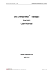
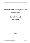
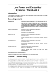
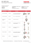
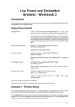
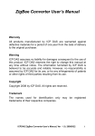
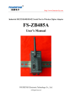
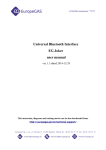
Wisen Innovation Technical Doc. No.2001 WISENMESHNET® Smart Gateway User Manual WISENMESHNET® Smart Gateway User Manual Wisen Innovation Ltd July 2014 Wisen Innovation Technical Doc. No.2001 WISENMESHNET® Smart Gateway User Manual Revision History and Clarification Rev. Issue Date Revisions Written By Revised By V5.0 20/06/2014 1st Issue Tony Shi Yan Wu V6.0 28/07/2014 2nd Issue Yan Wu Brian Jones V7.0 03/08/2014 3rd Issue Yan Wu Ian Wassell V8.0 06/08/2014 4th Issue Yan Wu Ian Wassell V9.0 17/09/2015 5th Issue: New Gateway Layout Figure Jun Zhang Yan Wu Added in the appendix. Document Definition: It defines the specifications (introduction, deployment and maintenance method) of WISENMESHNET® Smart Gateway, which is one of the key components in WISENMESHNET® Low Power, Intelligent, Wireless Sensor Network Monitoring system. Scope: Customer Site Project Managers and Engineers, Wisen Services Engineers. Notice : This documentation provides the basic instructions about the WISENMESHNET® Smart Gateway. Any further information can be requested by the customers. www.wiseninnovation.co.uk / www.wisencn.com Page - 2 - of 19 Wisen Innovation Technical Doc. No.2001 WISENMESHNET® Smart Gateway User Manual Table of Contents 1. Product Introduction .................................................................................................... - 4 2. System Structure Layout .............................................................................................. - 5 3. Features ........................................................................................................................ - 6 4. Smart Gateway Terminologies ..................................................................................... - 7 5. Operation Procedures .................................................................................................. - 7 5.1.Smart Gateway Location Choices ..................................................................... - 7 5.2.Deployment Procedures ................................................................................... - 8 5.3.Smart Gateway Mounting Options ................................................................. - 11 6. General Maintenance and Notification...................................................................... - 14 7. Package Information .................................................................................................. - 16 8. Safety and Warning .................................................................................................... - 17 9. Contact ....................................................................................................................... - 18 10. Appendix – New Gateway Layout ............................................................................ - 18 - www.wiseninnovation.co.uk / www.wisencn.com Page - 3 - of 19 Wisen Innovation Technical Doc. No.2001 WISENMESHNET® Smart Gateway User Manual 1. Product Introduction The WISENMESHNET® Smart Gateway is one of the key products in our patented WISENMESHNET® geotechnical safety monitoring system. Working together with the WISENMESHNET® Node products and our customers Vibrating Wire (VW) type sensors, it intelligently collects, converts and delivers the real-time information on the deformation of a structure to a remote server via its embedded GPRS module. The WISENMESHNET® Smart Gateway is powered with: A. a 100–240VAC as main power supply; B. or/and a 9-12VDC power supply; In addition, it has a rechargeable UPS to provide extra 7 days (minimum) mesh life to support data collection when both the AC mains and DC alternative power supplies are cut off. This product operates using our core technology, i.e., WISENMESHNET® Low Power, Intelligent, Wireless Sensor Network protocol. This product satisfies the three fundamental identities of the system: A. Network Life Span: to maximise battery life across the mesh network as a whole; B. Network Data Arrival Rate: to minimise data packet loss; C. Single Node Environmental Coverage: to maximise radio coverage. Our product has IP66 and CE marking and is designed to work in a tough environment. It is small in size, reliable in performance, easy for maintenance, has high precision during sampling, and has strong immunity to radio-interference. Figure 1. Smart Gateway Overview in Photos. www.wiseninnovation.co.uk / www.wisencn.com Page - 4 - of 19 Wisen Innovation Technical Doc. No.2001 WISENMESHNET® Smart Gateway User Manual 2. System Structure Layout www.wiseninnovation.co.uk / www.wisencn.com Page - 5 - of 19 Wisen Innovation Technical Doc. No.2001 WISENMESHNET® Smart Gateway User Manual 3. Features WISENMESHNET® Smart Gateway @ Typ. 25℃ Main Power Supply 100V~240V(AC) Alternative Power 9V – 12V(DC),typ. 9V(DC) Basics Supply Working Current Max. 2Amp@DC Power@GPRS Registration (Typ.) Operating Temperature -40℃~80℃ Storage 8GB Backhaul Wireless Interface GPRS (850/900/1800/1900MHz)@9600 bps Main Mesh Interface WISENMESHNET®Protocol@250kbps LxWxH 180 x 140 x 60mm Weight 1.5kg IP Rating IP66 AC Power IN - EMC-CMA14 Cable Gland DC Power IN - EMC-CMA12 AC IN – Green WAGO Internal Terminal Plugs Wire Connection DC/SO IN –Grey WAGO Internal Terminal Plugs Din Rail (Qty. x 2) Measurement Range -40℃~80℃ Resolution 0.5℃ Accuracy ±1℃ Antenna-2.4GHz Omni-directional 5dBi (20cm) or Customised Antenna-GPRS Omni-directional 3.5dBi (20cm) or Customised Antenna Connect SMA (Female) Protocol WISENMESHNET® Protocol / 802.15.4 Compatible Frequency Band 2.405GHz~2.480GHz (16 Channels) Sensor Fixing Bracket Radio Parameter Transmit Power < 1.5dBm 20dBm (Customised) Receive Sensitivity -103dBm -108dBm (Customised) WISENMESHNET® - The 3 Fundamental Identities Network Life Span Network Data Arrival Rate Single Node Environmental Coverage >= 36 months @ Tx power = ~ 0dBm (typical, 0.5dBm), antenna type 5dBi (omni-directional) @ sampling rate = 10mins; Capacity of 175 nodes has been tested. Into WISENMESHNET® greater than 99.5% i. Light concrete indoor environment ≥ Approx. 900 square meters ii. Underground tunnel environment ≤ Approx. ±200m (tunnel diameter = 3m, Tx, Rx antenna distance to the wall = 10cm) www.wiseninnovation.co.uk / www.wisencn.com Page - 6 - of 19 Wisen Innovation Technical Doc. No.2001 WISENMESHNET® Smart Gateway User Manual 4. Smart Gateway Terminologies Figure 2. Smart Gateway Terminologies. 5. Operation Procedures 5.1.Smart Gateway Location Choices Location: There are three fundamental considerations that are used by Wisen to identify available location for a Smart Gateway: 1) Firstly, the mesh coverage is the primary factor to be considered. It is vital to arrange the wireless www.wiseninnovation.co.uk / www.wisencn.com Page - 7 - of 19 Wisen Innovation Technical Doc. No.2001 WISENMESHNET® Smart Gateway User Manual mesh topology so that all the nodes in the system are connected. The recommended location of a Smart Gateway is in the centre of the network; 2) Secondly, GPRS coverage in the site must be available to ensure communication between a gateway and a remote server. The simplest way to check the signal availability on site will be to use a mobile phone having the same service operator as that of the Smart Gateway; 3) Thirdly, the power cable length, which relates to the cost of deployment or the DC power source availability. Once the location is chosen, you are ready to deploy your WISENMESHNET system. Figure 3. Smart Gateway Location Factors. 5.2.Deployment Procedures 1) Open the box: Take the Smart Gateway out of the package, open its lid; 2) SIM Card Installation: A Smart Gateway contains a 4-channel GPRS (850/900/1800/1900MHz)modem, which can be used globally. In the UK, it has been fully tested with Vodafone. While in China, it has been fully tested with China-Mobile and China-Unicom service providers. If you are in any other country, please consult with our Wisen engineers for the required changes; A. As shown in the figure below, insert the SIM into the plastic holder so the metal contacts are facing the shield, with the notch of the card at the top of the bracket; B. Slide the SIM all the way into the bracket; www.wiseninnovation.co.uk / www.wisencn.com Page - 8 - of 19 Wisen Innovation Technical Doc. No.2001 C. WISENMESHNET® Smart Gateway User Manual Push the SIM to the board and slide the metal bracket towards the edge of the shield to lock it in place. Figure 4. SIM Card Insertion. Warning: To insert/replace the SIM card, you MUST: a) Turn off both the mains AC and the DC power supply; b) Make sure the GPRS LEDs are completely off. 3) Antenna Installation: screw the antennas tightly onto the Smart Gateway. Figure 5. Mesh Antenna and GPRS Antenna. 4) Power on: by default, an AC plug has been connected on a Smart Gateway. However, before either the AC or the DC power is applied, please use a Multi-meter to check that the power supply voltage is suitable, as defined in the Feature table. Please follow the figure below to make the AC and the DC power connections: www.wiseninnovation.co.uk / www.wisencn.com Page - 9 - of 19 Wisen Innovation Technical Doc. No.2001 WISENMESHNET® Smart Gateway User Manual A. Unscrew the cable gland cover; B. Insert the cable through the cover and into the gland; C. Before any power cable is connected, ensure the AC supply is 100-240VAC and the DC supply is 9-12VDC by using a Multimeter. Note the DC power supply must be able to provide at least 2A current; D. Notice that gland EMC-CMA14 (the 14mm gland on the left) is used for the AC cable, which then is connected to the GREEN WAGO internal terminal plugs, where “L” – Live; “N” – Negative; “FG” – Ground; E. Notice that gland EMC-CMA12 (the 12mm gland on the right) is used for the DC cable, which then is connected to the GREY WAGO internal terminal plugs, where “DC+” and “-” are used for DC power supply; “SO+” and “–” are used for Solar power inputs [Notice : 9DVC is recommended]; a) Warning: incorrect power connection will cause serious damage. b) Warning: once the power cable(s) is connected, the gland cover must be firmly screwed to ensure the IP rating. Figure 6. Left: AC and DC Cable Connections; Right: AC Cable Connection. 5) GPRS Signal Check: By default, the Smart Gateway has already been configured and tested to send its received mesh data to a Wisen server, where we provide further services to our customers. Once the power is on, the green Power GPRS LED on the right is constantly lit while the Status GPRS LED on the www.wiseninnovation.co.uk / www.wisencn.com Page - 10 - of 19 Wisen Innovation Technical Doc. No.2001 WISENMESHNET® Smart Gateway User Manual left will show the sequence referred in Section.3., “Smart Gateway LED status”: i) Flashing once every 1s – network registering; ii) Flashing once every 3s – network connected; iii) Both the LEDs are off – restarting. 6) System LED Status: Terminology Working Status Otherwise Power LED Constantly ON Check the power supplies connections GPRS Power LED Constantly ON Contact with Wisen UPS Charging LED If ON, then recharging in progress battery full or not recharging MCU LED Constantly ON Contact with Wisen Flashing at 3s Otherwise – please check if you are using Flashing at 1s - registration the recommended GPRS service operator GPRS Status LED Table 1. System LEDs Status. MESH LED LED/Status Triggering Waiting Sampling Receiving - Red LED ON OFF ON ON - Yellow LED ON OFF OFF Flashing Once - Green LED ON ON ON OFF Table 2. Mesh LED Status. 7) To validate the sensor data, and to see if it works, please refer to << WISENMESHNET® System Evaluation User Guide >>. 5.3.Smart Gateway Mounting Options Depending on the installation surface, the Smart Gateway can be deployed using three different methods: 1)Flat Surface Fixing using Two Din Rails www.wiseninnovation.co.uk / www.wisencn.com Page - 11 - of 19 Wisen Innovation Technical Doc. No.2001 WISENMESHNET® Smart Gateway User Manual Step 1: Cap-Hex-Head Screw M6x14 (Qty. 4) – firmly screw two Din Rails to the back of the Smart Gateway box; Step 2: Anchor Bolt M6x70 (Qty. 4) (Drill size of M10) – firmly bolt the two din rails onto the flat surface. Figure 7. Smart Gateway - Two Din Rails Fixing. 2)Flat Surface Fixing using One Din Rail Step 1: Cap-Hex-Head Screw M6x14 (Qty. 2) – firmly screw one Din Rail to the back of the Smart Gateway box; Step 2: Anchor Bolt M6x70 (Qty. 2) (Drill size of M10) – firmly bolt one Din rail onto the flat surface. www.wiseninnovation.co.uk / www.wisencn.com Page - 12 - of 19 Wisen Innovation Technical Doc. No.2001 WISENMESHNET® Smart Gateway User Manual Figure 8. Smart Gateway - One Din Rail Fixing. 3)Column Fixing using Releasable Cable Ties Step 1: Cap-Hex-Head Screw M6x14 (Qty. 2) – firmly screw one Din Rail to the back of the Smart Gateway box; Step 2: Metal Releasable Cable Tie (Qty. 2 minimum) – thread cable tie through the Din Rail slots or through the gap between the Din Rail and the back of the Smart Gateway box, then tighten the cable ties around the column. Figure 9. Smart Gateway - Cable Tie. www.wiseninnovation.co.uk / www.wisencn.com Page - 13 - of 19 Wisen Innovation Technical Doc. No.2001 Notice WISENMESHNET® Smart Gateway User Manual : 1) When the deployment is complete, please ensure that at least one/both of AC and DC power supplies are turned on and the cable glands are tightened. Any unused gland should be sealed properly to maintain the IP rating of the box; 2) The Mesh backup UPS battery must be connected; 3) The GPRS Link LED should be flashing once every 3s; 4) Ensure that data is seen from the remote server; 5) Tighten the 4 Cap-Hex-Head screws on Gateway lid. 6. General Maintenance and Notification 1) Once the WISENMESHNET® Smart Gateway is installed and working, please do not interfere with it unless it is absolutely necessary; 2) The Smart Gateway relies on radio signals to communicate with the nodes. It must be deployed before the nodes and please ensure that it is not covered by any materials, which would block the radio signals, for example, chicken wire, aluminum sheet hoardings, etc.; 3) Please make sure the correct power voltage is supplied; 4) If no data is received from the Smart Gateway, then please carry out investigations in the following two stages: A. Remote Inspection of historical data, to identify: a) Whether the heart-beat message has been sent back successfully at each time interval; b) Whether the power supply voltage in the heart-beat message is as expected, if not, please check the power connection; c) Whether the signal strength has become significantly weaker, if yes, please check the antenna has been screwed on firmly; d) Whether the SIM card contract is valid and that payment is up to date. www.wiseninnovation.co.uk / www.wisencn.com Page - 14 - of 19 Wisen Innovation Technical Doc. No.2001 B. WISENMESHNET® Smart Gateway User Manual On-site Inspection: if all above are good, please arrange for an on-site inspection to check: a) Whether the Serial Gateway has visible external damage; b) Please check that the GPRS and Mesh antennas have not been swapped to the wrong connectors; c) Whether the antenna is bent or damaged and the node (gateway or sensor node) is not blocked by new construction, e.g., hoardings. Notices i. d) When it is possible, check that the signal strength is normal by using a spectrum analyser; e) Use a multimeter to check the AC power of 100 – 240VAC or the DC power of 9-12VDC; f) Whether any interface connectors are loose. : Case One: If any change has been made from the list above, please inspect the data from the remote server; ii. Case Two: If all the actions from the list above have not cured the problem, please contact Wisen. We will be happy to help. www.wiseninnovation.co.uk / www.wisencn.com Page - 15 - of 19 Wisen Innovation Technical Doc. No.2001 WISENMESHNET® Smart Gateway User Manual 7. Package Information Standard: No. Items mm Qty. 1 WISENMESHNET® Smart Gateway 200x150x55 1 2 User Manual - 1 3 Inspection Report - 1 4 2.4GHz 5dBi Omni-directional Antenna 200 1 5 GPRS Antenna 200 1 6 Din Rail 250x35 2 7 Cap-Hex-Head Screw M6x14 4 8 Anchor Bolt M6x70 4 Optional/Customer Preparation: No. Items Purpose 1 M6 Anchor Bolt Spanner Bolts to the mounting surface 2 M6 Cap-Hex-Head Screwdriver Screws between din rail and the back of the node box 3 M3 Cap-Hex-Head Screwdriver Screws on the lid 4 Metal Cable Tie For special mounting 5 Power Cable Gland Spanner Tighten the cable for its IP rating www.wiseninnovation.co.uk / www.wisencn.com Page - 16 - of 19 Wisen Innovation Technical Doc. No.2001 WISENMESHNET® Smart Gateway User Manual 8. Safety and Warning Warning: Please read the following instructions carefully. 1)Operation Safety Before taking any action, please read all the information provided carefully, and keep the guidance documents safe; Ensure that any procedure and installation are correctly carried out. The communication cable and the case must be grounded. This product has been designed to a certain water-proof level. However, it becomes water vulnerable when the lid is open or if the cable gland has not been sealed properly. 2)Electric Safety The Smart Gateway plays a crucial part in WISENMESHNET system. Please ensure that reliable power is supplied; Please strictly follow the power connection instructions and ensure that all connections are made correctly; Please make sure that the FG terminal on the AC power supply is connected to the ground properly; if not sure, please check using a multimeter, otherwise unexpected damage or injury may occur. 3)Warning This product must not be disassembled under any circumstances, to do so will void the warranty and may leave the product in a dangerous state; If all the above are not followed, the manufacturer cannot be held responsible for any damage and injury caused to the users. 4)Caution Danger of explosion if battery is incorrectly replaced. Replace only with the type recommended by the manufacturer. When disposing of the batteries, please contact your local authorities or dealer and ask for the correct method of disposal. www.wiseninnovation.co.uk / www.wisencn.com Page - 17 - of 19 Wisen Innovation Technical Doc. No.2001 WISENMESHNET® Smart Gateway User Manual 9. Contact - Wisen Innovation Ltd: www.wiseninnovation.co.uk - Email: [email protected] 10. Appendix – New Gateway Layout Version One: Gateway Layout (Released before 2015), Please refer to Version Two Gateway Layout as below. www.wiseninnovation.co.uk / www.wisencn.com Page - 18 - of 19 Wisen Innovation Technical Doc. No.2001 WISENMESHNET® Smart Gateway User Manual Version Two: Gateway Layout (Released after 2015). www.wiseninnovation.co.uk / www.wisencn.com Page - 19 - of 19