Download WISENMESHNET Tilt Node User Manual

Transcript
Wisen Innovation Technical Doc. No.2002
WISENMESHNET® Tilt Node (Dual-Axis) User Manual
WISENMESHNET® Tilt Node
(Dual-Axis)
User Manual
Wisen Innovation Ltd
July 2014
www.wiseninnovation.co.uk / www.wisencn.com
Page - 1 - of 16
Wisen Innovation Technical Doc. No.2002
WISENMESHNET® Tilt Node (Dual-Axis) User Manual
Revision History and Clarification
Rev.
Issue Date
Revisions
Written By
Revised By
V5.0
20/06/2014
1 Issue
st
Tony Shi
Yan Wu
V6.0
28/07/2014
2 Issue
nd
Yan Wu
Brian Jones
V7.0
03/08/2014
3 Issue
rd
Yan Wu
Ian Wassell
V8.0
06/08/2014
4 Issue
th
Yan Wu
Ian Wassell
Document Definition:
It defines the specifications (introduction, usage and maintenance method) of the Tilt Node, which is one of
®
the key components in WISENMESHNET Low Power, Intelligent, Wireless Sensor Network system.
Scope:
Customer Site Project Managers and Engineers, Wisen Services Engineers
Notice
:
®
This documentation provides the basic instructions about the WISENMESHNET Tilt Node. Any further
information can be requested by the customers.
www.wiseninnovation.co.uk / www.wisencn.com
Page - 2 - of 16
Wisen Innovation Technical Doc. No.2002
WISENMESHNET® Tilt Node (Dual-Axis) User Manual
Table of Contents
1. Product Introduction ............................................................................................................... - 4 2. System Structure Layout.......................................................................................................... - 5 3. Features ................................................................................................................................... - 6 4. Tilt Node Terminologies .......................................................................................................... - 7 5. Operation Procedures.............................................................................................................. - 7 5.1.System Deployment Notifications: .............................................................................. - 7 5.2.Reading Conversion to Structural Tilt Direction.......................................................... - 8 5.3.Deployment Procedures.............................................................................................. - 9 5.4.Tilt Node Mounting Options ..................................................................................... - 10 6. General Maintenance and Notification ................................................................................. - 12 7. Package and Accessories ....................................................................................................... - 14 8. Safety and Warning ............................................................................................................... - 15 9. Contact .................................................................................................................................. - 16 -
www.wiseninnovation.co.uk / www.wisencn.com
Page - 3 - of 16
Wisen Innovation Technical Doc. No.2002
WISENMESHNET® Tilt Node (Dual-Axis) User Manual
1. Product Introduction
®
The WISENMESHNET Tilt Node is one of the key products in our patented WISENMESHNET
®
®
geotechnical safety monitoring system. Working together with the WISENMESHNET gateway product and node
products, it intelligently delivers the real-time tilt deformation of a structure to the information centre.
®
®
The WISENMESHNET Tilt Node operates using our core technology, i.e., the WISENMESHNET Low Power,
Intelligent, Wireless Sensor Network protocol, together with its internal high precision MEMS tilt sensing module
and power unit. This product satisfies the three fundamental identities of the system:
A.
Network Life Span: to maximise battery life across the mesh network as a whole;
B.
Network Data Arrival Rate: to minimise data packet loss;
C.
Single Node Environmental Coverage: to maximise radio coverage.
Our product has IP66 and CE marking and is designed to work in a tough environment. It is small in size, reliable in
performance, easy for maintenance, has high precision during sampling, and has strong immunity to
radio-interference.
Figure 1. Tilt Node Overview in Photos.
www.wiseninnovation.co.uk / www.wisencn.com
Page - 4 - of 16
Wisen Innovation Technical Doc. No.2002
WISENMESHNET® Tilt Node (Dual-Axis) User Manual
2. System Structure Layout
www.wiseninnovation.co.uk / www.wisencn.com
Page - 5 - of 16
Wisen Innovation Technical Doc. No.2002
WISENMESHNET® Tilt Node (Dual-Axis) User Manual
3. Features
®
WISENMESHNET Tilt Node @ Typ. 25℃
Basics
Power Supply
Qty. x 1 (3.6V D-Cell 32650)
Stop/Min. Voltage
2.1VDC
Battery Connection
Standard Metal Battery Holder
Working Current (DC)
Max. 20mA (Typ.)
Operating Temperature
-40℃ to 80℃
Storage
300 Messages during Meshing
LxWxH
100 x 100 x 60mm
Weight
0.8kg
Fixing Bracket
Din Rail (Qty. x 2) or Customised Bracket for Angular Surface
IP Rating
IP66
Certificate
CE
®
Interface
Sensor
Radio Parameter
Mesh Wireless Interface
WISENMESHNET Protocol@250kbps
Inspection Period
Every 2 Years
Inspection Method
Manufacturer Calibration
Main Sensor
MEMS Tilt Sensor
Parameter
X-axis (or A-axis); Y-axis (or B-axis)
Tilt Range
-5° to +5° (or Customised)
Accuracy
0.01°
Long Term Stability
0.004°
Resolution
0.005°
Auxiliary Sensor
Temperature
Temperature Range
-40 to 80℃
Accuracy
0.5℃
Antenna-2.4GHz
Omni-directional 5dBi (20cm) or Customised
Antenna Connect
SMA (Female)
Protocol
WISENMESHNET® Protocol / 802.15.4 Compatible
Frequency Band
2.405GHz~2.480GHz (16 Channels)
Transmit Power
< 1.5dBm
20dBm (Customised)
Receive Sensitivity
-103dBm
-108dBm (Customised)
®
WISENMESHNET - The 3 Fundamental Identities
Network Life Span
Network Data Arrival Rate
Single Node Environmental
Coverage
>= 36 months @ Tx power = ~0dBm (typical, 0.5dBm), antenna type 5dBi (omni-directional) @
sampling rate = 10mins
Into WISENMESHNET® greater than 99.5%
i.
Light concrete indoor environment ≥ Approx. 900 square meters
ii.
Underground tunnel environment ≤ Approx. ±200m (tunnel diameter = 3m, Tx, Rx antenna
distance to the wall = 10cm)
www.wiseninnovation.co.uk / www.wisencn.com
Page - 6 - of 16
Wisen Innovation Technical Doc. No.2002
WISENMESHNET® Tilt Node (Dual-Axis) User Manual
4. Tilt Node Terminologies
Figure 2. Tilt Node Internal Configuration Terminologies.
5. Operation Procedures
5.1.System Deployment Notifications:
1)
Location: The deployment location of a Tilt Node is usually determined by the desired monitoring or
inspection location;
2)
Before any Tilt Node is switched on, a gateway must be deployed, powered on and proven to be working
properly. Otherwise, the nodes will need to be switched off and on again after a gateway is switched on. So
www.wiseninnovation.co.uk / www.wisencn.com
Page - 7 - of 16
Wisen Innovation Technical Doc. No.2002
WISENMESHNET® Tilt Node (Dual-Axis) User Manual
simply speaking, the rules to follow when deploying and turning on a WISENMESHNET system are:
Gateway first, then nearby nodes, then further nodes.
3)
All the tilt node should face to the same direction, and clear notes must be taken so that the tilt direction of a
monitored structure can be correctly interpreted;
4)
The Tilt Nodes have a certain measurement range, please set it up at around 0 degree readings; [Notice
:
this can be done by two methods, i.e., using a spirit level or using readings from the Tilt Node itself.]
5)
All the Tilt Nodes must be oriented upwards, i.e.,
, or
;
6)
All the Serial Numbers of the Tilt Nodes must be recorded against their site references.
5.2.Reading Conversion to Structural Tilt Direction
For the Dual-Axis Tilt Node, we define one axis as the “A-axis rotation”, the other as the “B-axis rotation”. To verify
the rotational directions according to the data readings on both A and B, please see the table shown below:
Node Orientation
Rotation
Angular Reading (in degrees)
Clockwise Rotation
On B-axis increases
Anti-Clockwise Rotation
On B-axis decreases
Rotating outside the page
On A-axis increases
Rotating into the page
On A-axis decreases
Or equivalently,
Figure 3. Top Down View of a Tilt Node.
(A+ represents when a Tilt Node is rotating toward the vertical arrow in the figure, the angular reading on the
A-axis increases;
B+: represents when a Tilt Node is rotating toward the horizontal arrow in the figure, the angular reading on the
B-axis increases)
www.wiseninnovation.co.uk / www.wisencn.com
Page - 8 - of 16
Wisen Innovation Technical Doc. No.2002
WISENMESHNET® Tilt Node (Dual-Axis) User Manual
5.3.Deployment Procedures
1)
Open the box: Take the node out of the package and open its lid;
2)
Insert Battery: By default, a node does not contain a D-Cell battery. Therefore the battery needs to be
inserted.
Notice
3)
: +ve and –ve orientation must be correct, otherwise, the internal circuit may be damaged;
Antenna Installation: screw the antenna tightly onto the node;
Figure 4. Mesh Antenna.
4)
Power On: switch on the Tilt Node by pressing the square button on the top-right corner. Now you should be
able to see 3 LEDs flashing 3 times, this means the node is on. Then switch off the node to save power if the
gateway is off;
Figure 5. Battery Installation and Power On/Off Switch (highlighted in yellow circle).
www.wiseninnovation.co.uk / www.wisencn.com
Page - 9 - of 16
Wisen Innovation Technical Doc. No.2002
5)
WISENMESHNET® Tilt Node (Dual-Axis) User Manual
®
To validate the sensor data, and to see it works, please refer to << WISENMESHNET System Evaluation User
Guide >>.
Notice
: To properly deploy a node, you must firstly have a Smart Gateway turned on before a node is powered
on. Otherwise, a powered-on isolated node will consume most of its power performing a mesh network searching
mode. Therefore battery life is shortened significantly.
5.4.Tilt Node Mounting Options
Notice
: There is only one aim while fixing the Tilt Node, that is to make sure that the top/bottom of the
node box is horizontal so that the Tilt Node maximum range is not exceeded and so ensuring that optimum
readings can be taken in both the A and B axes.
The node fixings must be rigid for the sensor to measure accurate data. Do not use different fixing types, e.g.,
top and bottom, to avoid thermal effects. Movement in the fixings will affect the readings.
Depending on the installation surface, the Tilt Node can be deployed using two different methods:
1) Flat Surface Fixing using Two Din Rails
Step 1: Cap-Hex-Head Screw M6x14 (Qty. 4) – firmly screw two Din Rails to the back of the node box;
Step 2: Anchor Bolt M6x70 (Qty. 4) (Drill size of M10) – firmly bolt two Din Rails onto the flat surface.
Front View
Side View
Figure 6. Surface Fixing – Dual Din Rails.
2) Angular Surface Fixing using One L-Shaped Bracket
www.wiseninnovation.co.uk / www.wisencn.com
Page - 10 - of 16
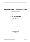
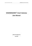
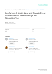
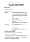
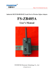
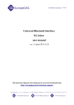
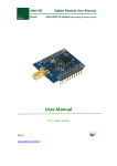
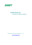
Wisen Innovation Technical Doc. No.2002
WISENMESHNET® Tilt Node (Dual-Axis) User Manual
Step 1: Screw (NOT tightly) the L-Shaped Bracket onto the back of the node box using Cap-Hex-Head Screws
M6x14 (Qty. 4).
®
Figure 7. WISENMESHNET Tilt Node onto an L-Shaped Bracket.
Step 2: Bolt the L-Shaped Bracket firmly onto the angular surface using the Anchor Bolts M6x70 (Qty. 4)
(Drill size of M10). Level the node using a spirit level attached onto the top of a node, to within 1 degree of
horizontal, then tighten all the bolts and screws.
Figure 8. Angular Wall Mounting.
www.wiseninnovation.co.uk / www.wisencn.com
Page - 11 - of 16
Wisen Innovation Technical Doc. No.2002
WISENMESHNET® Tilt Node (Dual-Axis) User Manual
Front View
Side View
Figure 9. Angular Wall Mounting on a Vertical Surface Overview.
6. General Maintenance and Notification
1) Once a Tilt Node is installed in the field, please minimise any man-made disturbance so that data
quality can be maintained;
2) Radio communication will be impaired if the antenna is covered by metal or very moist soil material;
3) Due to the discharge characteristics of the recommended battery, a battery replacement should be carried out
when a node reported voltage reaches 2.7V, at which point you have approximately 3 weeks to change the
battery;
4) Our product will use all the possible capacity in a battery down to a stop (minimum) voltage, which has been
specified in the Features table. When this occurs, our WISENMESHNET protocol will send you a warning then it
will enter a deep sleep mode until a new battery is installed;
5) If the data from nodes are shown unexpected results or are not being sent back to the Wisen gateway, then
please carry out investigation using the following two stage procedure:
A. Remote Inspection of historical data, to identify the following:
a)
Whether the heart-beat message has been sent back successfully at each time interval;
b)
Whether the battery voltage is too low, if yes, please change the battery unit;
c)
Whether the signal strength has become significantly weaker than it was previously. If yes, please
www.wiseninnovation.co.uk / www.wisencn.com
Page - 12 - of 16
Wisen Innovation Technical Doc. No.2002
WISENMESHNET® Tilt Node (Dual-Axis) User Manual
check the antenna has been screwed on firmly.
B.
On-site Inspection: If all the above are good, please arrange an on-site inspection to check:
a)
Whether the Tilt Node has visible external damage;
b)
Check the box lid to see if it is firmly tightened;
c)
Whether the antenna is bent or damaged and that the node is not blocked by new construction,
e.g., hoardings;
d)
When it is possible, check that the signal strength is normal by using a spectrum analyser;
e)
Open the lid, to see whether the battery is firmly attached to its holder;
f)
Use a multi-meter to measure the battery voltage. If it is below the stop (minimum) voltage, replace
the battery.
Notices
:
i. Case One: If any change has been made from the list above, please inspect the data from the remote server;
ii. Case Two: If all the actions from the list above have not cured the problem, please contact Wisen. We will be
happy to help.
www.wiseninnovation.co.uk / www.wisencn.com
Page - 13 - of 16
Wisen Innovation Technical Doc. No.2002
WISENMESHNET® Tilt Node (Dual-Axis) User Manual
7. Package and Accessories
Standard:
No.
Items
Dimension (mm)
Qty.
1
WISENMESHNET Tilt Node
100x100x60
1
2
User Manual
-
1
3
Inspection Report
-
1
4
2.4GHz 5dBi Omni-directional Antenna
200
1
5
Din Rail
250x35
2
6
Cap-Hex-Head Screw
M6x14
4
7
Anchor Bolt
M6x70
4
®
Optional/Customer Preparation:
No.
Items
Purpose
1
Angular Bracket
Mounting on an angular surface
2
Battery
For the node
3
M6 Anchor Bolt Spanner
Bolts to the mounting surface
4
M6 Cap-Hex-Head Screwdriver
Screws between din rail and the back of the node box
5
M3 Cap-Hex-Head Screwdriver
Screws on the lid
6
Metal Cable Tie
For special mounting
www.wiseninnovation.co.uk / www.wisencn.com
Page - 14 - of 16
Wisen Innovation Technical Doc. No.2002
WISENMESHNET® Tilt Node (Dual-Axis) User Manual
8. Safety and Warning
Warning: Please read the following instructions carefully.
1)Operation Safety
 Before taking any action, please read all the information provided carefully, and keep the guidance documents
safe;
 Ensure that any procedures and installations are correctly carried out. The communication cable and the case
must be grounded.
 This product has been designed to meet a certain water-proof level. However, it becomes water vulnerable
when the lid is open or if the cable gland has not been sealed properly.
2)Electric Safety
 To install the battery into a holder, please follow the “+” (positive) and “-” (negative) signs in any Wisen
product. Wrong orientation of a battery could potential cause unit damage. Notice
: The orientation of
battery can vary among products.
 When disconnecting the battery, please take special care not to apply excessive force, otherwise the battery
holder and the nearby circuitry may be damaged.
3)Warning
 The battery in the product has a relatively high capacity, so please take special care during storage and usage.
 This product must not be disassembled under any circumstances, to do so will void the warranty and may
leave the product in a dangerous state;
 If all the above are not followed, the manufacturer cannot be held responsible for any damage and injury
caused to the users.
4)Caution
 Danger of explosion if battery is incorrectly replaced. Replace only with the type recommended by the
manufacturer.
 When disposing of the batteries, please contact your local authorities or dealer and ask for the correct
method of disposal.
www.wiseninnovation.co.uk / www.wisencn.com
Page - 15 - of 16
Wisen Innovation Technical Doc. No.2002
WISENMESHNET® Tilt Node (Dual-Axis) User Manual
9. Contact
- Wisen Innovation Ltd: www.wiseninnovation.co.uk
- Email: [email protected]
www.wiseninnovation.co.uk / www.wisencn.com
Page - 16 - of 16