1
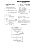
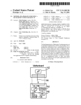
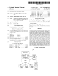
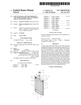
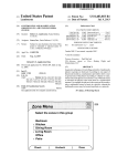
US008339457B1
(12) Ulllted States Patent
(10) Patent N0.:
Heinke
(54)
(45) Date of Patent:
SYSTEMS AND METHODS FOR
7,459,107 B2 *
TIME-SHARED MEMORY ACCESS IN A
,
_
(75)
Inventor:
(73)
Assignee: Fluke Corporation, Everett, WA (US)
*
~
.
Thomas Heinke, Santa Cruz, CA (US)
~
~
~
-
given III et a1~
,
r
y
7,897,919 B2 *
3/2011
King ........................... .. 250/330
2004/0021773 A1*
2/2004
HayakaWa .
2005/0104771 A1
5/2005 Terry er a1,
2006/0017821 A1
2007/0034798 A1*
2007/0087311 A1
1/2006 Garvey et al.
2/2007 Hamrelius et al. .......... .. 250/332
4/2007 Garvey et al.
2008/0211915
A1
9/2008
.. 348/164
McCubbrey
Subject‘ to any d1scla1mer, the term ofth1s
Zoos/0308732 A1
patent 1s extended or adjusted under 35
USC 15401) by 1658 days-
2009/0009596 A1
V2009 Kerr et 31‘
2010/0277595 Al* 11/2010 Reed etal. .................. .. 348/164
(21) Appl. N0.: 11/711,886
12/2008 Wamke et a1‘
OTHER PUBLICATIONS
_
(22)
Dec. 25, 2012
12/2008 Yamashita et al. ......... .. 264/40.1
g?
THERMAL IMAGING DEVICE
( ) Not1ce.
US 8,339,457 B1
Fluke Corporation, “InsideIR Thermal Image Analysis Software,”
Flled:
Feb‘ 28’ 2007
User’s Manual, 38 pages, Jan. 2006.
Fluke Corporation, “Ti20 Thermal Imager,” Users Manual, 68 pages,
Int. Cl.
Jan‘ 2006‘
H04N 5/33
(2006.01)
(52)
US. Cl. ....... .. 348/164; 348/166; 250/330; 250/332
(58)
Field of Classi?cation Search ........ .. 348/l64il68;
250/33(L334
See application ?le for complete search history.
(56)
4/1992
Ennenga et al. ............ .. 250/334
11/1992 Johnson
1/1995 Pietyetal.
6/1997 Pietyetal.
5,677,532
5,812,112
5,856,931
6,594,621
10/1997
9/1998
1/1999
7/2003
A
A
A
B1
8/2003
6,849,849 B1
2/2005 Warner et al.
7,454,050 B2
embodiments, the imaging device can include an imaging
engine, a memory device for storing image data, and a pro
cessor for receiving the image data from the imaging engine,
storing the image data in the memory device, retrieving the
image data from the memory device, and transmitting the
Duncan et al.
Helfferich
McCasland
Meeker
6,606,115 B1*
ABSTRACT
local display and on a remote display is disclosed. In some
5/1991 Imanishi
5,160,842 A
5,386,117 A
5,637,871 A
(74) Attorney, Agent, or Firm * Perkins Coie LLP
An imaging device for real-time display of image data on a
U.S. PATENT DOCUMENTS
5,107,117 A *
Primary Examiner * Bharat N Barot
(57)
References Cited
5,014,129 A
* cited by examiner
image data to both a local display and remote display so that
the image data can be vieWed on both the remote display and
Alicandro et al. .......... .. 348/164
local display simultaneously.
20 Claims, 3 Drawing Sheets
11/2008 Garvey
I
Storing image data in a memory device (301)
I
I
Retrieving image data from the memory device in a first time slot (302)
I
I
Transmitting the retrieved data to a host computerfor remote display (303)
I
I
Retrieving image data from the memory device in a second time slot (304)
I
I
Transmitting the retrieved data to an LCD for local display (305)
I
I
Displaying the retrieved data on a local display (306)
I
I
Displaying the retrieved data on a remote display (307)
I
US. Patent
Dec. 25, 2012
Sheet 1 of3
mm?ow?
US 8,339,457 B1
om?
US. Patent
Dec. 25, 2012
Sheet 2 of3
US 8,339,457 B1
Namv
N122
%~\@ON\BN\8N\3N
N5SN05
Nmvhk
0803man09:_>8w<~:eg_8w
ENmg:28m@m8
q6E8
V
o
m
03
8mNewSN/
wC
N| .
US. Patent
Dec. 25, 2012
Sheet 3 of3
US 8,339,457 B1
Storing image data in a memory device (301)
V
Retrieving image data from the memory device in a first time slot (302)
V
Transmitting the retrieved data to a host computer for remote display (303)
V
Retrieving image data from the memory device in a second time slot (304)
V
Transmitting the retrieved data to an LCD for local display (305)
Displaying the retrieved data on a local display (306)
Displaying the retrieved data on a remote display (307)
FIG. 3
US 8,339,457 B1
1
2
SYSTEMS AND METHODS FOR
TIME-SHARED MEMORY ACCESS IN A
THERMAL IMAGING DEVICE
ponents in an imaging device to alloW for real-time display of
image data simultaneously on both a host computer and on an
attached LCD.
Camera Management Board
An imaging device can include a Camera Management
TECHNICAL FIELD
Board (CMB) Which can include components for supporting
an imaging engine. An example CMB is illustrated in FIG. 1.
The following is related to a system architecture for sharing
memory access among components in an imaging device and,
more particularly, for sharing memory access to alloW for
real-time display of image data on both a remote display and
a local display.
The CMB 101 of an imaging device 100 can be coupled to an
imaging engine 105 for capturing image data and can include
an external interface 110, a central processor 120, memory
125, memory 130, and a signal processor 135. The CMB 101
can be further coupled to local LCD 140 via central processor
120. These components can be coupled in the manner
describedbeloW. As a non-limiting example, in some embodi
BACKGROUND
ments, memory 125 can be a SRAM (static random access
memory) and memory 130 can be a non-volatile memory,
Infrared thermal imaging instruments are commonly used
for obtaining temperature pro?les of objects such as indus
trial machines or components of operating equipment.
Inspecting an object’s operating temperature conditions can
reveal Whether a failure is imminent or a machinery adjust
ment is necessary.
such as a ?ash ROM.
20
The central processor 120 of the CMB 101 can be any type
of processor that can be con?gured to transport data betWeen
various functional units of the CMB 101 and perform other
logical and/or processing functions. As examples, central
Imaging instruments typically sense an image using an
processor 120 can be an FPGA (?eld programmable gate
array of sensors and store data representing the scene in a
array), an ASIC (application-speci?c integrated circuit), or
memory located in the instrument. The stored image data can
then be presented to a user on a local display integrated into
25
any other type of device that can be con?gured to operate on
or otherWise process image data.
Imaging Engine
the imaging instrument. Typically, the stored image data can
also be transferred to a host computer for remote display and
The imaging device can include any one of various differ
further processing.
To date, existing imaging solutions have not been capable
ent types of imaging engines. When used for infrared imag
of imaging a scene using a sensor array in an imaging device
and displaying a real-time image of the scene on both an
integrated or local display and on a remote display on a host
30
computer. For quite a feW applications, hoWever, it is desir
able to display an image on both a local display on an imaging
instrument and on a remote display in real-time, as Well as to
ing, the imaging engine can include an infrared array, a lens,
an electronics for supporting the array and for performing the
primary signal processing to convert a scene to an output
signal comprised of an array of temperatures. In one embodi
ment, the imaging engine 105 can be an SCC500 provided by
BAE Systems.
35
As illustrated in FIG. 1, the imaging engine 105 can have a
bi-directional auxiliary data port 106 and a primary tempera
provide additional bene?ts.
ture data port 107. The temperature array data can be output
from port 107 via a high speed serial LVDS (loW voltage
differential signaling) line. In some embodiments, output port
BRIEF DESCRIPTION OF THE DRAWINGS
FIG. 1 illustrates a block diagram of components for an
40
imaging device.
107 can be con?gured to output a signal With a period of 163
ns or a frequency of 6.136 MHZ. Auxiliary port 106 can be
coupled to sWitch 115. Operation of sWitch 115 is discussed
FIG. 2 illustrates a timing diagram for memory sharing in
in more detail beloW. Imaging engine 105 also can be used to
store ?rmWare for its operation. As described in more detail
an imaging device.
FIG. 3 illustrates a method for real-time imaging.
The headings provided herein are for convenience only and
beloW, the output of primary temperature data port 107 can be
do not necessarily affect the scope or meaning of the claimed
invention.
provided to a host computer for remote display and also can
be processed in the imaging device 100 for display on a local
LCD.
DETAILED DESCRIPTION
50
In a broad sense, systems and methods for operating and
imaging device to sense and store image data are disclosed in
detail beloW. An imaging engine forming part of the imaging
device can include any form or type of imaging array. In some
embodiments, the imaging array can be a tWo-dimensional
array of sensors con?gured to record infra-red thermal image
55
Camera Management Board Local Image Storage
Image data captured by imaging engine 105 can be output
through output port 107. In some embodiments, imaging
engine 105 can output data on primary temperature data port
107 Without knoWing the status of components to Which it is
coupled. The imaging engine 105 can be con?gured to oper
ate continuously in the absence of input instructions. HoW
ever, a device such as interface controller 110 may not alWays
be ready to receive data and a direct connection from primary
output 107 to interface controller 110 may therefore not be
desirable. For example, even if interface controller 110 is
coupled to a relatively fast shared bus line, there may be other
devices on the bus Which prevent interface controller 110
data. In other embodiments, the imaging array can be con?g
ured to record visible-light images.
While these systems and methods described herein are
applicable to portable imaging devices, they can also be used
in immobile devices, permanently tethered devices, or in any
other device or environment in Which image data is trans
ferred betWeen an imaging engine and a host computer or
from sending its data.
Where image data is to be synchroniZed in real-time betWeen
local and remote displays.
be processed by central processor 120 and then stored into
The systems and methods described herein can be used for
sharing access to a single-port memory among various com
To alleviate this condition, the data at output port 107 can
65
memory 125. After storage in memory 125, memory 125 can
provide, by Way of central processor 120, the image data to
signal processor 135 for further processing. Imaging device
US 8,339,457 B1
3
4
100 can also include a button such as a shutter button (not
embodiments, interface 110 controller can be an EZUSB chip
shown) Which can be actuated to cause the image data to be
available from Cypress Semiconductor.
Written into a non-volatile memory such as memory 130. To
Once data is stored in the FIFO on the interface controller
110, the data can then be moved into a host computer via
output line 111 When the imaging device 100 is coupled to a
host computer. In some embodiments, When not connected to
a host computer, the memory 130 remains connected to signal
processor 135. HoWever, to avoid address con?icts When the
imaging device 100 is connected to a host computer, the
signal processor 135 can be put into a quiet mode so that it
further improve data How, interface controller 110 can
include a buffer such as a FIFO. In some embodiments, the
buffer can have 512 bytes of storage. In this manner, image
data can be sensed and stored While a host computer is not
connected to the imaging device.
Camera Management Board Image Recall for Local Display
CMB 101 can be used to retrieve data for display on a local
or attached LCD screen. Image data can be retrieved from
does not use the address bus.
The state machine inside central processor 120 can move
memory 130 and loaded into signal processor 135. The image
data can be processed in signal processor 135 and then be
stored into the memory 125 through central processor 120.
data from memory 125 into interface controller 110 Which
then provides the data to a host computer. At the host com
puter, a softWare application can be used to make the data
Once stored in memory 125, an internal state machine Which
drives LCD 140 can be used to retrieve the image data from
memory 125 via central processor 120.
Signal processor 135 can be used to perform various pro
cessing functions on the image data. For example, signal
available to a user and can store the data for further process
mg.
Camera Management Board Parameter Storage
20
In some cases, it may be desirable to doWnload parameter
data to the imaging device from a host computer. For
processor 135 can be used to overlay display controls Which
example, routing information canbe doWnloaded to the imag
can appear With a thermal image on the LCD 140. In some
ing device. SoftWare running on a host computer can be used
embodiments, memory 125 and memory 130 can both store
to set up a route. This route data can then be doWnloaded to the
the same array of temperature data. For example, image data
imaging device. Systems and methods for routing are further
can be stored in a non-volatile memory such as memory 130 25 described in US. patent application Ser. No. ll/463,234
entitled “SYSTEM AND METHOD FOR CONFIGURING
A THERMAL IMAGING INSTRUMENT,” the contents of
and then copied to an SRAM such as memory 125 before
display.
In some embodiments, for local display of image data, a
data signal on primary temperature data port 107 is received
by central processor 120 and stored into memory 125. Data is
then read from memory 125 by signal processor 135 through
Which are herein incorporated by reference in their entirety.
30
Route data from host computer can be doWnloaded to
memory 130. The route data can be received by interface
controller 110, forWarded to central processor 120, and pro
action of central processor 120. The data processed by signal
cessed by signal processor 135. Signal processor 135 can then
processor 135 is then stored in a memory 125. Image data in
memory 125 can then moved by central processor 120 from
memory 125 to LCD 140.
35
store the data in memory 130. This method can also be used to
store a ?rmware update for the system and for the user inter
face. A non-volatile memory such as memory 130 can be used
40
to store routing information, image data, and user interface
information.
Signal processor 135 can be con?gurable to operate in
different modes. In some embodiments, signal processor 135
can have an EMIF (Extended Memory Interface) mode. In
Camera Management Board Image Recall for Remote Dis
Play
In some circumstances, a user may Wish to transfer tem
perature data to a host computer for further processing and
display of data on host computer. For example, softWare
running on a server computer can be used to draW an area of
this mode, the signal processor 135 can act as a microcontrol
interest on an image and perform various functions such as
ler. That is, the commands and data can be provided from an
calculating average temperatures and checking temperatures
against prede?ned limits, generating and creating alarms, etc.
external source. Signal processor 135 can also operate in a
Using the systems and methods described herein, real-time
HPI (Host Port Interface) mode. In this mode, internal RAM
45
data can be transferred to the host computer via external
interface controller 110 Without interrupting processing
inside imaging device 100. The external interface controller
110 can be any interfacing means for transferring data
betWeen a host computer and a peripheral device. In some
embodiments, a USB protocol can be used. In other embodi
ments, a FireWire protocol or any other protocol can be used.
Central processor 120 can be used to coordinate the pro
cessing of image data. Central processor 120 can be used to
provide address data for the memory 130. Central processor
50
110. The interface controller 110 can include a microcontrol
ler With a USB (Universal Serial Bus) engine. Interface con
60
105, set target emissivity, etc. In some embodiments, auxil
iary port 106 can be a loW-speed serial connection.
At times, it may be desired to doWnload calibration infor
mation to the imaging engine 105. SWitch 115 can be used to
select betWeen interface controller 110 and signal processor
65
135. In some embodiments, sWitch 115 can support bi-direc
tional communications. SWitch 115 can be operable accord
some embodiments, interface controller 110 can include a
USB state machine and a FIFO memory. The state machine
Thus, interface controller 110 can operate on its oWn. In some
port 106 can be implemented according to the RS422 serial
communication protocol. The auxiliary data port 106 can be
coupled sWitch 115. The auxiliary port 106 can be used to
send and receive setup parameters, and to see information
such as example internal temperatures of the imaging engine
troller 110 can be connected to a USB or other bus on port 116
can be con?gured to determine When data is in the controller’ s
FIFO and the controller 110 can transfer data from the FIFO
to the USB bus on port 116. As long as the internal buffer is
not full, interface controller 110 can receive additional data.
the signal processor 135 betWeen HPI and EMIF modes. The
signal can be on line 136 Which is used to couple interface
controller 110 to signal processor 135.
Camera Management Board Calibration Mode
Auxiliary port 106 can be used for purposes other than
transferring image data. In some embodiments, auxiliary data
55
120 can move data into a FIFO buffer on interface controller
and connected to internal systems on ports 117 and 118. In
is accessible from outside and the memory appears as
memory to outside World. The signal processor 135 can oper
ate on data stored in the memory.
Interface controller 110 can be used to signals a sWitch at
ing to the RS422 protocol.
US 8,339,457 B1
6
5
Thus, a ?rmware update or calibration commands can be
received from a host computer on signal line 111 at interface
controller 110. Interface controller 110 can output the cali
bration commands on port 117 to sWitch 115. From sWitch
In some embodiments, memory 125 can have one address
bus and one data bus. In such embodiments, one component
can address memory 125 at a time. As described above, vari
ous different systems may have access demands on memory
115, the data or commands canbe moved to auxiliary port 106
125. For example, temperature data port 107 of imaging
engine 105 may continually produce temperature data to be
stored in memory 125. The high data-rate from imaging
engine 105 places relatively high access demands on memory
125. Additionally, LCD 140 can have relatively strict timing
on imaging engine 105. Calibration commands can be sent to
and received from imaging engine 105. Calibration of the
imaging engine 105 can be performed Without the use of
signal processor 135 or memory 130. During calibration,
real-time data can still be received from imaging engine 105
by central processor 120 via output port 107.
For example, imaging engine 105 can include a shutter. A
shutter temperature can be measured in the imaging engine
requirements based on its refresh rate. Other non-temperature
data may also need to be retrieved from or stored in memory
125.
By time-sharing memory 125, memory 125 can be imple
105 and used as a reference temperature for calibration pur
mented as a single-port memory. Access to memory 125 can
poses. Internal temperatures can also include temperatures of
the imaging array. This temperature data as Well as other
be divided into an arbitrary number of time slots. In some
embodiments, six time slots can be used. Thus, memory 125
can effectively function as a multi-port memory by time slices
calibration data can be transferred to central processor 120 or
to a host computer using the systems and methods described
above.
Additionally, data and parameters can be loaded from sig
and thereby permit the pseudo-simultaneous access by mul
tiple devices such as imaging engine 105, LCD 140, signal
20
nal processor 135 to imaging engine 105. Auxiliary port 106
can be used to modify parameters at the imaging engine 105.
Image data from imaging engine 105 can temporarily
stored in central processor 120 and then moved to memory
125. Thus, memory 125 canbe used as a buffer to synchronize
For example, emmissivity data can be sent to the imaging
engine 105 via the auxiliary port. Temperature calculation
?rmware can also be stored in imaging engine 105. These
processor 135 and interface controller 110.
timings of imaging engine 105 and the interface controller
25
systems and methods can also be used to upload neW ?rm
110. In some embodiments, central processor 120 can also
include one or more FIFOs or buffers for storing the image
Ware in imaging engine 105 through sWitch 115.
Imaging engine 105 can also send parameter data to signal
processor 135 through sWitch 115. For example, the auxiliary
data from temperature data port 107.
With reference to FIG. 2, in time slot 201, if data is avail
able from imaging engine 105, it is Written into memory 125.
port 106 can be used to request additional data not available at
output port 107. This additional data can include shutter tem
30
to an address generator driven by imaging engine 105. In time
perature data or engine temperature data Which can be used to
slot 202, memory 125 can be connected to interface controller
110 for read and Write access by a host computer. At this time,
generate diagnostic Warning signals. These systems and
methods can be used to calibrate, recalibrate, or test imaging
engine 105.
interface controller 110 can function as an address counter. In
35
Shared Memory Access
As discussed above, imaging engine 105 may be con?g
ured to produce data on the temperature data port 107 data
Without reference to other events on imaging device 100.
Memory 125 can be used to store data from imaging engine
105. Memory 125 can also be used for storing a locally
40
displayed image. The imaging device can be con?gured to
storing display data in one portion of memory 125 and imag
time slot 203, memory 125 can be coupled to LCD 140 for the
purpose of refreshing the screen. In time slots 204-206,
memory 125 can be coupled to signal processor 135. At time
slot 207, the memory access cycle can restart. Time slots
207-209 as illustrated therefore correspond to time slots 201
203. In some embodiments, each display color red 210, green
211, and blue 212, can be transferred using tWo time slots.
An exemplary method for processing image data in an
imaging device is illustrated in FIG. 3. The method can
ing data in another portion of memory 125 so that a user can
revieW an image While the imaging engine 105 is running and
At this time, the address bus on memory 125 canbe connected
45
creating neW data Which is stored into memory 125.
include storing the image data in a memory device (301),
retrieving image data from the memory device in a ?rst time
slot (3 02), transmitting the retrieved data to a host computer
In some embodiments, memory 125 can be 512 KB, a
for remote display (3 03), retrieving image data from the
portion of Which is used for image data. Memory 125 can also
be used to buffer image data from imaging engine 105. When
memory device in a second time slot (304), transmitting the
retrieved data to an LCD for local display (305), displaying
the retrieved data on a local display (306), and displaying the
the buffer on interface controller 110 is ready, central proces
sor 120 retrieves data from memory 125 and transfers the data
into the buffer in interface controller 110 until the buffer is
full. As discussed above, the buffer canbe a FIFO. Data canbe
stored in the buffer of interface controller 110 until the buffer
is full or the controller 110 is otherWise not ready.
50
retrieved data on a remote display (307).
In some embodiments, the image data retrieved during the
?rst time slot and second time slot can represent the same
thermal imaging temperature data. In other embodiments, the
In some modes, signal processor 135 retrieves data,
manipulates it, then stores the data into memory 125 so that it
image data retrieved in the ?rst time slot and second time slot
can represent different portions of the stored thermal imaging
temperature data. In some embodiments, either of the data
can be available for display on LCD 140. Additionally, the
retrieved in the ?rst and second time slots can be transmitted
55
data in memory 125 can be made available to a host computer.
Thus, at any time, unmodi?ed image data in memory 125 or
processed data from signal processor 135 stored in memory
to either a remote display or a local display.
60
CONCLUSION
125 can be retrieved. It may be useful to display a real-time
image on a host computer and on the imaging device simul
taneously. Image data can also be received from a host com
puter and stored into memory 125 for local display on LCD
140. In some embodiments, signal processor 135 may move
data from one location to another Within memory 125.
Many speci?c details of certain embodiments of the inven
65
tion are set forth in the description and in FIGS. 1-3 to provide
a thorough understanding of these embodiments. A person
skilled in the art, hoWever, Will understand that the invention
may be practiced Without several of these details or additional
US 8,339,457 B1
7
8
details can be added to the invention. Well-known structures
and functions have not been shown or described in detail to
invention encompasses not only the disclosed embodiments,
but also all equivalent Ways of practicing or implementing the
invention under the claims.
While certain aspects of the invention are presented beloW
in certain claim forms, the inventors contemplate the various
aspects of the invention in any number of claim forms. For
example, While only one aspect of the invention is recited as
avoid unnecessarily obscuring the description of the embodi
ments of the invention. As used herein, one or more compo
nents “coupled” to each other can be coupled directly (i.e., no
other components are betWeen the coupled components) or
indirectly (i.e., one or more other components can be placed
a means-plus-function claim under 35 U.S.C sec. 112, other
aspects may likeWise be embodied as a means-plus-function
claim. Accordingly, the inventors reserve the right to add
betWeen the coupled components).
Unless the context clearly requires otherwise, throughout
the description and the claims, the Words “comprise,” “com
additional claims after ?ling the application to pursue such
additional claim forms for other aspects of the invention.
prising,” and the like are to be construed in an inclusive sense,
as opposed to an exclusive or exhaustive sense; that is to say,
in the sense of “including, but not limited to.” Additionally,
I claim:
the Words “herein,” “above,” “beloW,” and Words of similar
import, When used in this application, shall refer to this appli
1. A thermal imaging device, comprising:
an imaging engine con?gured to generate thermal image
data, the thermal image data representing a tWo-dimen
sional array of temperature values;
cation as a Whole and not to any particular portions of this
application. Where the context permits, Words in the above
Detailed Description using the singular or plural number may
also include the plural or singular number respectively. The
a memory device for storing the thermal image data gen
20
Word “or,” in reference to a list of tWo or more items, covers
all of the folloWing interpretations of the Word: any of the
items in the list, all of the items in the list, and any combina
tion of the items in the list.
The above detailed description of embodiments of the
erated by the imaging engine; and
a processor con?gured to
alternately access the memory device to retrieve a ?rst
portion of the thermal image data for transmitting for
display on a local display and to retrieve a second
25
portion of the thermal image data for transmitting for
invention is not intended to be exhaustive or to limit the
display on a remote display, Wherein the displays on
invention to the precise form disclosed above. While speci?c
embodiments of, and examples for, the invention are
described above for illustrative purposes, various equivalent
modi?cations are possible Within the scope of the invention,
the local display and the remote display occur during
overlapping time periods.
2. The thermal imaging device of claim 1, Wherein the
30
order, alternative embodiments may perform routines having
steps, or employ systems having blocks, in a different order,
having access to the memory device.
35
and some processes or blocks may be deleted, moved, added,
subdivided, combined, and/ or modi?ed to provide alternative
or subcombinations. Each of these processes or blocks may
be implemented in a variety of different Ways. Also, While
processes or blocks are at times shoWn as being performed in
40
series, these processes or blocks may instead be performed in
parallel, or may be performed at different times.
The teachings of the invention provided herein can be
light of the above Detailed Description. While the above
description describes certain embodiments of the invention,
image data; and
45
50
55
intended to be interpreted in its broadest reasonable manner,
even though it is being used in conjunction With a detailed
description of certain speci?c embodiments of the invention.
Certain terms may even be emphasiZed; hoWever, any termi
nology intended to be interpreted in any restricted manner
Will be overtly and speci?cally de?ned as such in this
Detailed Description section. In general, the terms used in the
folloWing claims should not be construed to limit the inven
tion to the speci?c embodiments disclosed in the speci?ca
tion, unless the above Detailed Description section explicitly
de?nes such terms. Accordingly, the actual scope of the
transmit the thermal image data to the processor for storing
in the memory device.
6. The thermal imaging device of claim 1, further compris
ing an interface controller coupled to the processor, the inter
face controller con?gured to:
receive the thermal image data from the ?rst processor; and
store the thermal image data in an internal buffer.
and describes the best mode contemplated, no matter hoW
detailed the above appears in text, the invention can be prac
ticed in many Ways. Details of the system may vary consid
erably in its implementation details, While still being encom
passed by the invention disclosed herein.
The terminology used in the Detailed Description is
4. The thermal imaging device of claim 1, further compris
ing a local display and Wherein the thermal image data is
simultaneously displayed on both the local display and the
remote display.
5. The thermal imaging device of claim 1, further compris
ing a signal processor coupled to the processor, the signal
processor con?gured to:
receive the thermal image data from the processor;
perform one or more processing functions on the thermal
applied to other systems, not necessarily the system described
above. The elements and acts of the various embodiments
described above can be combined or altered to provide further
embodiments.
These and other changes can be made to the invention in
memory device is a single-port memory.
3. The thermal imaging device of claim 1, Wherein the
memory device has a predetermined number of ports, the
number of ports being feWer than the number of devices
as those skilled in the relevant art Will recogniZe. For
example, While processes or blocks are presented in a given
60
7. The thermal imaging device of claim 6, Wherein the
interface controller is further coupled to a signal processor for
selecting an operating mode of the signal processor.
8. The thermal imaging device of claim 6, Wherein the
interface controller is further con?gured to transmit the stored
thermal image data to a host computer.
9. The thermal imaging device of claim 1, further compris
ing a sWitch coupled to an auxiliary data port on the imaging
engine for coupling the auxiliary data port to either an inter
face controller or a signal processor.
10. The thermal imaging device of claim 9, Wherein the
interface controller is con?gured to receive calibration data
from a host computer and transmit that data through the
65
sWitch to the imaging engine.
11. A method for processing image data captured on an
imaging device, comprising:
US 8,339,457 B1
9
10
17. The method of claim 11, further comprising receiving
receiving by a camera management module thermal image
data from an imaging engine, Wherein the thermal image
data comprises a tWo-dimensional array of temperature
calibration data from a host computer and transmitting that
data through a sWitch to the imaging engine.
18. A system for processing image data captured on an
values;
storing by the camera management module the thermal
image data in a memory device; and
alternately accessing the memory device to retrieve a ?rst
portion of the thermal image data for display on a remote
display and to retrieve a second portion of the thermal
image data for display on a local display, Wherein the
displays on the remote display and the local display
01
a receiving means for receiving thermal image data from an
imaging engine, Wherein the thermal image data com
prises a tWo-dimensional array of temperature values;
a storing means for storing the thermal image data in a
memory device;
an alternately accessing means for alternately accessing
occur during overlapping time periods.
12. The method of claim 11, Wherein the memory device is
a singleport memory device.
the storing means to retrieve a ?rst portion of the data
and a second portion of the data; and
a transmitting means for transmitting the ?rst portion of the
data for display on a local display and the second portion
of the data for display on a remote display, Wherein the
13. The method of claim 11, further comprising simulta
neously displaying the thermal image data on both the local
display and the remote display.
14. The method of claim 11, further comprising:
accessing the thermal image data by a signal processor;
displays on the local display and the remote display
occur during overlapping time periods.
performing one or more processing functions on the ther
mal image data by the signal processor; and
storing the thermal image data in the memory device.
15. The method of claim 14, further comprising:
20
receiving the thermal image data from the ?rst processor at
an interface controller; and
storing the thermal image data in a buffer internal to the
interface controller.
16. The method of claim 15, further comprising selecting
an operating mode of the signal processor at the interface
controller.
imaging device, comprising:
25
19. The system of claim 18, further comprising a means for
simultaneously displaying the thermal image data on both the
local display and the remote display.
20. The system of claim 18, further comprising a means for
coupling the memory device to a plurality of other devices
each of Which can access the memory device through a single
port.