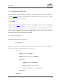
1
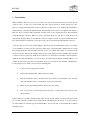
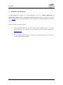
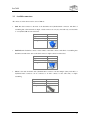
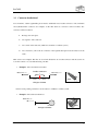
•
•
LeoCAM
1
Introduction
With LeoCAM we intend to get as close as possible to the way we interact with real Lego models in the real
world. In order to do this, we've observed that Lego parts (pieces) interact in certain specific ways. Two
pieces are connected through specific connectors they have on their body. As an example, the brick family is
characterized by connecting through their Studs and Stud Inlets. If we restrict our example to this family, a
Stud can only be connected with a Stud Inlet, and this creates a bond between the pieces that holds them
joined through this connection. But if we want to split them appart, we only have to break the bond by
disconnecting the parts. Thus, we introduce the connector concept: a connector is a piece element that allows
the connection with its connterparts on other pieces. Two pieces only can interact through their connectors.
Now, let's take a look on a more useful example to ilustrate all the power behind this concept: Let's assume
you are building a car. The car body is formed by simple parts of the brick family, which interact by joining
them through their Stud and Stud Inlets. But the car also has wheels. The wheels are connected at the
extremes of an axle, which in turn is firmly attached to the car through a part with a cylindrical hole and studs
to attach it to the rest of the body. With the aid of this new tool, the wheels are attached to the axle with two
simple mouse clicks each. But then, you won't be able to pass the wheels through the Cylindrical Hole, as you
wouldn't be able in the real world, since the wheels won't let you connect the axle with the cylindrical hole.
So, the actual process to finish your car would be something like:
1
Connect one axle ending with one wheel.
2
Connect the Cylindrical Hole with the other axle ending.
3
Slide the cylindrical hole up to its final position. If you want, try to slide further, to the other side
of the axle. The first wheel you connected won't let you pass through!
4
Finally, connect the remaining wheel to the now-free axle ending.
5
Now, you can rotate on wheel and the other will rotate, too! Even better, the car doesn't rotate,
only the wheels!
In this example, if you want to further laterally adjust the axle and the wheels as a whole with respect to the
car, you will only have to translate the set again, but this time limited by both wheels, or you just can move
one wheel and the set will slide up to the Cylindrical Hole. You won't be able to dissassemble the car without
explicitly doing so!
2
LeoCAM
2
About the LeoCAM project
LeoCAM (Mechanical LeoCAD) is a final undergraduate project for "Technical Engineering on
Management Computer Science" at Universitat of Girona. This application is an extension of the widely
known LeoCAD package and the main difference with LeoCAD is the assembling implementation added to
this new version.
We want to clarify two important aspects:
1
Users must understand this is only a beta version and thus it might have bugs, so we want to
recieve suggestions and comments about user interface and any possible LeoCAM bugs to
[email protected].
2
We are not native english speakers, so we expect everyone who reads this paper to excuse us for
possible grammar/spelling mistakes.
3
LeoCAM
3
Connectors
We define a connector as a part of a piece, which can allow us to make an assembling between two pieces.
For example, the 2 x 2 brick ( 3003 ) connect through their Stud and Stud Inlets. The same happens for other
type of connectors like Axles, Cylindrical Holes, etc.
3.1
Type of connectors
The connectors can be classified as:
1
Spot-like. This kind of connectors can be interpreted like a point in a 3D space ( see Figure 1
below for an example in the case of a Stud ). Studs and Stud Inlets belong to this this family.
Right view
3D perspective view
Figure 1. Spot-like connector.
2
Segment-like. The segment connectors are connectors which own a body of a certain lenght l
that allow them to assemble to N opposite connectors at the same time ( see Figure 2 ). Example
of this type are Axles, Rods and Cylindrical Holes. Special note must be taken to the fact that
Axles actually are two connectors, one from each extreme up to the middle ( See section 3.3 ).
Right view
3D perspective view
Figure 2. Segment-like connector.
Connectors can also be clasify as simple and multiple connectors: the former can only be connected with one
and only other connector, while the latter can be connected to several opposite connectors at the same time.
4
LeoCAM
3.2
Available connectors
All connectors, in the current version, at LeoCAM are:
•
Stud. The Stud connector is the male of the Stud Inlet and Cylindrical Hole connectors. The kind of
assembling that a Stud can make is simple: a Stud connector can only be joined with only one Stud Inlet
or one Cylindrical Hole at the same time.
Name
Type
Kind of assembling
Example
•
Stud
Spot - Male
Simple
Stud Inlet. The Stud Inlet connector is the female of the Stud connector. The kind of assembling that
Stud Inlet can make is the same as the Stud connector: simple connection with a Stud.
Name
Type
Kind of assembling
Example
•
Stud Inlet
Spot – Female
Simple
Axle.It is the male Axle Hole and Cylindrical Hole connectors and has multiple (many Axle Hole or
Cylindrical Hole connectors can be connected to an Axle connector at the same time) or simple
assembling.
Name
Type
Kind of assembling
Example
Axle
Segment - Male
Multiple
5
LeoCAM
•
Axle Hole.The Axle Hole connector is an Axle female and, as the Axle connector, the Axle Hole can
assemble on a multiple or simple basis.
Name
Type
Kind of assembling
Example
•
Axlel Hole
Segment - Female
Multiple
Cylindrical Hole.This connector is another female to the Axle connector and can also make multiple
or simple assembling. Connections with Studs at the extremes of the Cylindrical Hole are also
possible.
Name
Type
Kind of assembling
Example
Cylindrical Hole
segment - Male
Multiple
6
LeoCAM
3.3
Connector brotherhood
For convenience, certain segment-like pieces must be subdivided in two brother connectors. Axle, Axle Hole
and Cylindrical Hole connectors are examples of this. But when two connectors will be brothers? Two
connectors will be brothers if:
1
Belong to the same piece.
2
Are segment – like connectors.
3
Are coaxial on the same axis ( Main axis on LDraw coordinate system ).
4
Are consecutive ( One of the two extremes of the segment that represent each connector are the
same ).
Here we have two examples. The first one is an Axle divided into two brother connectors and the second one
is an Axle connector too, but without having a brother.
•
Example 1. Axle1 and Axle2 are brothers.
Main Axis Axle1
brother connectors
.
A
Axle1
B
Axle2
.
C
Main Axis Axle2
3704
3704 piece Schema
Positive Z axis pointing outwards for each connector on LDraw coordinate system.
•
Example 2. Axle without brotherhood.
Main Axis Axle
.
A
B
32013
32013 piece Schema
7
LeoCAM
3.4
Connector’s state
The connectors of a piece could be classify as either free or busy connectors. This distinction is very
important because the user will only be able to select free connectors. Busy connectors will have a reference
to the connector or set of connectors, in the case of a segment – like connectors, with which they are
assembled. So, every assembled connector will know to which connector it is connected ( see Figure 3 ).
Figure 3. The Stud Inlet from piece A knows that it’s assembled with Stud from piece B
and the other way round.
The connectors state can be classfied by the type of the connectors:
•
Point – like connectors state. A point – like connector will be consider free connector if has no
connector connected and will be consider busy connector i has a connector assembled to it ( see
Figure 4 ). So when a spot – like connector is on a busy state, it can’t be consider like a free
connector and other way round.
Free Stud
Busy Stud Inlet
Free Stud Inlet
Busy Stud
Figure 4. Example of free and busy spot – like connectors.
8
LeoCAM
•
Segment – like connectors state. A segment – like connector will be consider as a free connector if
its extreme is free too. Otherwise, if its extreme is busy the connector will be consider like a busy
connector. So a segment – like connector can be consider as a free and busy connector at the same
time ( see Figure 5 ).
Axle
Free
Free
Axle
Busy
Busy
CH
Axle
Free
Axle
Busy
CH
Free
Busy
CH CH CH
Figure 5. Example of segment – like connectors state.
9
LeoCAM
4
4.1
Usage features
Assembling pieces through their connectors
Assembling is the process of connecting two pieces by its connectors. To perform an assembling between
pieces we need to follow the following steps:
1
Select the connectors we want to assemble. We can select a connector by "clicking" on it with
the left mouse button. We want to clarify that Axle, Axle Hole and Cylindrical Hole connectors
can only be selected by their extremes, so the assembling can only be by the extremes too.
2
Make assembling. To confirm the assembling, we only have to "double click" on one of the two
selected connectors to be assembled with the left mouse button. The connector where we double
click will be known as the static connector and the other as the dynamic connector. These are
important concepts, because the transformations to acomodate the pieces together will be applied
to the last one.
After the two previous steps will be another one in which the user doesn’t participate due to it is done
automathically by LeoCAM. This step is the propagation of the assembling. It consists to verify if, after the
assembling, there are more connections resulting from the first one (see Figure 6 ).
Brick 1 x 1
Brick 1 x 1
Brick 1 x 1
1
1
2
3
This is the initial model with three pieces from the brick
family.
10
LeoCAM
2
3
Model without piece B. The Stud connector from piece C,
and the Stud Inlet from piece A are now free connectors.
Stud from piece D must be connected with Stud Inlet from
piece A, and the same for the Stud from C and the Stud
Inlet connector from piece D.
If we manually make the connection D-A, connection D-C
will be performed automatically.
Figure 6. Example of propagating assembling done by LeoCAM.
4.2
Translating and rotating assembled pieces
When we have an assembled model, we can translate or rotate it. Because of the model is "physically"
assembled, the pieces connected to the one we want to rotate or translate will be rotated or translated too, and
consecuently the pieces connected to the connected ones will be translated or rotated and so on recursively...
There is one aspect about rotating that must be emphasized. If you rotate an Axle, connected to a Cylindrical
Hole, and the rotation is over the axis of the Cylindrical Hole, it won’t perform the rotation because the Axle
connector can freely rotate over the Cylindrical Hole and other way round. On the other side, if a Cylindrical
Hole connected to a Stud connector rotates over the axis of its body, the connected one will rotate because of
the properties of the Cylindrical Hole connection with Stud connector ( see Figure 7 ).
Figure 7. Example of free rotating of an Axle over a Cylindrical Hole connector.
11
LeoCAM
4.3
Sliding Axle, Axle Hole or Cylindrical Hole connectors
When segment – like connector is assembled to another connector of the same type, we can slide one of the
two connectors over the other. This is a very useful option because we can only make assembling using Axle,
Axle Hole and Cylindrical Hole connectors by their extremes. So when they are assembled, we can slide and
select in which position we want them ( see Figure 8 ).
Figure 8. Example of the slidding process.
We must understand that the slide action is not only a translation. When a connector slides over another, it can
result in the formation of new connections and the elimination of others, (así como) the possible changing of
the connector state. Thus, in every slide action we must recalculate all the assemblings between the slided
connector ( the dynamic connector ) and the rest of the model ( the static connectors ) to determinate the
connections and the state of the pieces connectors.
When we slide the blue Axle to the right, the
assembling between it and the red Axle disappears and
appears a new connection between the Axle and the
first green Axle Hole.
12
LeoCAM
Another important thing to comment about the sliding process is that, when we slide a connector and its piece
has some others connectors assembled to it, we must translate recursively the connected pieces to the one that
has the sliding connector.
Translation
When we slide the Cylindrical Hole over the Axle, the
piece connected to the Cylindrical Hole piece, must be
translated in the direction we slide.
Sliding connector
( Cylindrical Hole ).
13
LeoCAM
4.4
Collision detection
This feature is implemented only on the translation and sliding process. Let’s see some examples to
understand it:
Collision detection on translation.
The collision detection on the translation assembled pieces is implemented in the Axle – Cylindrical Hole
connection when one of the two connectors are translating trough their main axis.
•
Example 1. When we translate the piece that owns the Axle connectors (P1) through the main axis of
the Cylindrical Hole1 or Cylindrical Hole2, the first Cylindrical Hole will collision with the Axle
Hole2, which is connected to the Axle1. When the collision has been detected, the Axle Hole2 will
push the piece that owns the two Cylindrical Holes (P2).
Piece to translate
P2
P3
P1. 3704 piece schema.
P1
A1
A2
AH1
AH2
CH1
CH2
P2. 6541 piece schema.
P3. 32064 piece schema.
dcollision
•
Example 2. In this example the Cylindrical Hole2 is translated to the left. The piece that owns the
Cylindrical Hole one and two (P2) is connected indirectly to the piece that owns the Cylindircal
Holes
three and four (P3). The collision detection can resolve cases like these, so when the
Cylindrical Hole3 crashes with the Axle Hole2, the whole model will translate due to the pushing of
the Cylindrical Hole caused by the translation of the Cylindrical Hole2.
14
LeoCAM
P4
P1
P5
A1
AH1
AH2
P3
CH3
P1. 3704 piece schema.
P2
CH4
P2. 6541 piece schema.
A2
P3. 6541 piece schema.
P4. 3622 piece schema.
CH1 CH2
P5. 32064 piece schema.
dcollision
Piece to translate
•
Example 3. The collision detection on translations can resolve cases in which segment – like
connectors without brothers participate. In this example the Axle is being translated to the left
through the main axis of the Cylindrical Holes. So when the extreme of the Axle (without brother)
crashes with Cylindrical Hole2, the piece that owns it (P2) will be translated too due to the
connector’s collision.
Piece to translate
P2
A
P1
P1. 6587 piece schema
CH1
CH2
P2. 6541 piece schema.
dcollision
15
LeoCAM
Collision detection on sliding.
•
Example 1. The Axle Hole1 can slide to the right until the extrem of the Axle Hole2, connected to de
Axle2. To the left, the Axle Hole1 can slide up to the infinity (Shaded pieces are static with respect to
the Axle that does not slide).
Slidding part
P2
P3
P1. 3704 piece schema.
P1
A1
A2
AH3
AH4
P2. 32064 piece schema.
P3. 32064 piece schema.
AH1 AH2
∞
•
Slidding region
Example 2. The slidding part can slide to the left until the nearest extreme of the Axle Hole1 and to
the right until the nearest extreme of the Axle Hole2.
Slidding part
P2
P3
P4
P5
P1. 3704 piece schema.
P1
A1
A2
AH1 AH2
AH3 AH4
AH6
CH1 CH2
AH5
Slidding region
P2. 32064 piece schema.
P3. 3700 piece schema.
P4. 32064 piece schema.
P5. 32064 piece schema.
16
LeoCAM
•
Example 3. The piece that owns the Axle Hole1 and Axle Hole2 (P2) can slide until infinity to the
left, and to the right until the end of the Axle connector, because it doesn’t have a brother.
Slidding part
P1
P1. 32013 piece schema.
Axle
P2. 32064 piece schema.
AH1 P AH2
2
∞
Sliding region
17
LeoCAM
4.5
Load a model with LCI pieces
The saved files have no information about assembling, so the loaded files neither, but when LeoCAM opens a
compatible LeoCAD file extension ( DAT and LDR ), LeoCAM searches for LCI pieces and try to assemble
them in the position they are found in the file.
5
LCI files
Every part from the LDraw package which can perform an assembling must have associated a LCI ( Lego
Connectors Information ) file. In these files, which are plain text files, we'll find all the necessary connector
information associated to each Lego part. As an example, if the piece is defined in the 3005.dat file, it must
have associated a 3005.lci file, because the LeoCAM application needs to obtain all the connectors
information from the piece with the 3005 reference number.
5.1
Format and syntax
The LCI files name have the following format:
piece_number.lci
Every line in a LCI file is totally independent to any other line in the same file. The contents of an LCI file
and the syntax are written as XML format, and are the following:
<connector>
<name>connector_name</name>
<matrix>a b c d e f g h i j k l m n o p</matrix>
<parameters>
<lenght>connector_lenght</lentght>
<id>LCI_identificator_connector</id>
<brother>LCI_identificator_brother</brother>
</parameters>
</connector>
18
LeoCAM
where
•
connector_name is the name of the current connector. In the current version the possible values
are: stud, studInlet, axle, axleHole and cylindricalHole.
•
a b c d e f g h i j k l m n o p are the components from a 3D transformation matrix in
homogeneous coordinates ( see Figure 9 ). This matrix informs to LeoCAM about connector
rotation and position respect to the piece that owns the connector. That coordinate matrix is in
the LDraw coordinate system (see Figure 10 ).
Figure 9. Matrix from the LCI files.
•
Figure 10. LDraw coordinate system.
connector_lenght is the lenght of the connector ( Only in Axle, Axle Hole and Cylindrical Hole
connectors ).
•
LCI_identificator_connector is the id connector inside the LCI file ( Only in Axle, Axle Hole
and Cylindrical Hole connectors ).
•
LCI_identificator_brother is the id of the brother's connector. Two connectors are brothers if
both ( Only in Axle, Axle Hole and Cylindrical Hole connectors ):
-
Belong to the same piece.
-
Are Axle, Axle Hole or Cylindrical Hole connectors (both the same type).
-
Are coaxial in the same axis ( Main axis on LDraw coordinate system ).
-
And are consecutive connectors ( One of their extrems coincide ).
19
LeoCAM
The LCI file syntax has been created following the XML standard. The meaning of each tag is:
<connector> beginnig of connector's information.
</connector> ending of connector's information.
<name> beginnig of connector's name.
</name> ending of connector's name.
<matrix> beginning of 3D transformation matrix connector
</matrix> ending of 3D transformation matrix connector.
<parameters> beginning of connector's parameters.
</parameters> ending of connector's parameters.
<lenght> beginning of connector's lenght.
</lenght> ending of connector's lenght.
<id> beginning of connector's identificator
</id> ending of connector's identificator.
<brother> beginning of brother's identificator.
</brother> ending of brother's identificator.
20
LeoCAM
We want to clarify two important things about the syntax of a LCI file:
1
The <parameters> tag is only added in the Axle, Axle Hole and Cylindrical Hole connector
definitions, so Stud and Stud Inlet will ignore if this tag appears in a LCI file.
2
The <lenght> tag must be always be included inside the parameters, therefore is not optional.
3
The <id> and <brother> parameters are optional and only must be included if the connector has
a brother. Both parameters always appear at the same time, so the first one can’t appear without
the second one and the other way round.
5.2
LCI directory
The LCI files are included in a LCI directory. This directory might be selected by
button
in
the
assembling toolbar. By default, leoCAM searches the LCI folder in the same place that the LeoCAM
executable is.
5.3
Create a model using LCI and non LCI files
We want to clarify that we can create models using LCIed pieces (with its LCI files associated) and non LCI
pieces at the same time. The only difference is that non LCI parts will not have available connectors to select
and so to perform assembling.
21
LeoCAM
5.4
Available LCI files
LCI files
Brick family
2456
2465
3002
3003
2356
3001
2357
3001P02
3004P01
3004P02
3004P03
3004P012
3004P0RC
3005-3
3005-AE
3005-G
3005-M
3005-S
3005-Y
3008P02
3009P02
3010P05
3010P20W
3010P918
30145
3004P020
3005
3005-4
3005-B
3005-H
3005-N
3005-T
3005-Z
3008P03
3009P03
3010P06
3010P21
3010P924
30145P01
3004P050
3005-0
3005-5
3005-C
3005-I
3005-O
3005-U
3006
3008P21
3009P21
3010P08
3010P30
3010P928
3062-OLP
3704
3737
3701
4519
32064
32013
2577
3003PE1
2877
3004
3004P04
3004P05
3004P06
3004P051
3005-1
3005-6B
3005-D
3005-J
3005-P
3005-V
3007
3008P22
3010
3010P09
3010P31
30136
3062A
3004P060
3005-1B
3005-7
3005-E
3005-K
3005-Q
3005-W
3008
3009
3010P03
3010P15
3010P40
30137
3063
3004P090
3005-2
3005-A
3005-F
3005-L
3005-R
3005-X
3008P01
3009P01
3010P04
3010P20B
3010P41
30144
3065
3706
6541
3707
32000
Technic family
3705
32073
4143
3700
6587
22
LeoCAM
6
User interface
User can find an assembling toolbar on the LeoCAM application with the available assembling options:
5
1
2
7
3
6
4
1
Enable / Disable assembling.
2
Assemble two selected connectors.
3
Disconnect one busy connector.
4
Disconnect all the busy connectors from a piece.
5
Slide segment – like connector
6
Select the LCI fólder.
Incompatibilities
The only known incompatibilities between the assembling extensions and the rest of the LeoCAD package
are:
8
1
Groups. We are now studing the posibility to make it compatible.
2
Undo and Redo. We are trying to include this option for the final LeoCAM release.
Future releases
In the final LeoCAM release we will try to:
1
Solve some LeoCAM bugs and inherited ones from the original LeoCAD which concerns about
rotating parts.
23
LeoCAM
Appendix 1. DTD and XML Schema for LCI files
1
DTD
The purpose of a Document Type Definition (DTD) is to define the legal building blocks of an XML
document. It define the document structure with a list of valid elements. The DTD for LCI files is the
following:
< ! DOCTYPE connector [
< ! ELEMENT connector ( name, matrix, parameters ? ) >
< ! ELEMENT name ( #PCDATA ) >
< ! ELEMENT matrix ( #PCDATA ) >
< ! ELEMENT parameters ( lenght , (id , brother ) ? ) >
< ! ELEMENT parameters ( lenght , id ?, brother ? ) >
< ! ELEMENT id ( #PCDATA ) >
< ! ELEMENT lenght ( #PCDATA ) >
< ! ELEMENT brother ( #PCDATA ) >
]>
24
LeoCAM
2
XML Schema
XML Schema is an XML based alternative to DTD. An XML Schema describes the structure of an XML
document. The purpose of an XML Schema is to define the legal building blocks of an XML document, just
like a DTD. The main differences between the DTD and the XML Schema are:
•
XML Schemas are extensible to future additions.
•
XML Schemas are richer and more useful than DTDs.
•
XML Schemas are written in XML.
•
XML Schemas support data types.
•
XML Schemas support namespaces.
The XML Schema for LCI files is the following:
< xs : element name="connector" >
< xs : complexType >
< xs : sequence >
< xs : element name="name" type="nameType" />
< xs : element name="matrix" type="matrixType" />
< xs : element name="parameters" type="parametersType" minOccuers="0" />
< / xs : sequence >
< /xs : complexType >
< / xs : element >
< xs : simpleType name="nameType" >
< xs : restriction base="xs : string" >
< xs : enumeration value="stud" / >
< xs : enumeration value="studInlet" / >
< xs : enumeration value="axle" / >
< xs : enumeration value="axleHole" / >
< xs : enumeration value="cylindricalHole" / >
< /xs : restriction >
< / xs : simpleType >
< xs : simpleType name="matrixType" >
< xs : restriction base="xs : decimal" >
< xs : pattern value="\d{16}" / >
< /xs : restriction >
< / xs : simpleType >
25
LeoCAM
< xs : simpleType name="lenghtType" >
< xs : restriction base="xs : decimal" >
< xs : minInclusive value="0" / >
< /xs : restriction >
< / xs : simpleType >
< xs : complexType name="parametersType" >
< xs : sequence >
< xs : element name="lenght" type="lenghtType" / >
< xs : element name="id" type="xs : integer" / >
< xs : element name="brother" type="xs : integer" / >
< /xs : sequence >
< / xs : complexType >
26