1
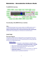
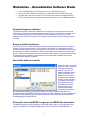
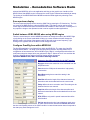
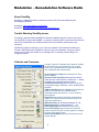
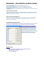
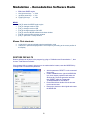
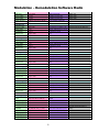
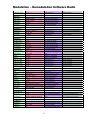
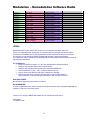
Modulation – Demodulation Software Radio
MDSR-SA/CAT User Manual V3.0
By ON6MU, Guy Roels, © 2010-13 ON6MU
Aalst/Belgium
MDSR-J Engine, Alex Schwarz, © 2010-13 VE7DXW
Vancouver/Canada
OmniRig © Alex Shovkoplyas, VE3NEA
MDSR homepage: http://users.skynet.be/myspace/mdsr/
MDSR support group:
http://groups.yahoo.com/group/mdsradio/
ON6MU homepage: http://www.qsl.net/on6mu
OMNIRIG homepage: http://www.dxatlas.com/OmniRig/
FREEWARE
1
Modulation – Demodulation Software Radio
MDSR V2.51 -- MDSR-SA 3.0 – OmniRig
Intro:
The MDSR-SA spectrum analyzer has been designed by Guy Roels (ON6MU) primarily for use
with the MDSR-J modulator – demodulator application designed by Alex Schwarz (VE7DXW).
It uses OmniRig to communicate with the transceiver and MDSR-engine. OmniRig is a universal
CAT interface and can communicate with 48 different makes and models of transceivers.
OmniRig was designed by Alex Shovkoplyas (VE3NEA).
This software package integrates the computer with the HF transceiver and creates a
sophisticated and easy to use interface and it provides functionality otherwise only found in high
end transceivers. This de-modulator is designed to work with a single-ended 12kHz IF signal
provided to the mic or line input of a soundcard. Unlike all other SDR software, this program will
work with the LIF2012 PCB or both single-ended down-converters described on the website
http://users.skynet.be/myspace/mdsr.
The advantage of using an existing transceiver is that today’s commercial amateur radios are
very rugged and they also have a very good IP3 intercept point. All the other low priced SDR
hardware is very prone to cross-modulation in strong signal conditions.
Now, with the additional modulator, the MDSR software can upgrade older shortwave
transceivers to the latest SDR interface with all the DSP features only found in high end units.
The BiLIF interface takes advantage of the sturdiness of commercial radios and the MDSR
provides the graphic user interface and signal processing. An existing radio can be upgraded
and enhanced without a lot of expense.
Changes and updates in the MDSR-SA software release
Summary:
The MDSR Team has been hard at work developing the next step of the DADPsoftware. The
MDSR synthesizer provides a full RX – TX capable DSP engine and utilizes the soundcard to
convert the digital audio stream into an analog 12kHz TX IF output. The MDSR-SA is the
companion software and was derived from the DADP-SA.
The development of the original CAT interface was discontinued and, instead, the OmniRig CAT
interface was implemented for greater functionality and compatibility with 48 transceivers.
2
Modulation – Demodulation Software Radio
The MDSR software offers the following features
MDSR-SA: spectrum analyzer and function display
• 6 Memory banks to store popular frequencies and fast recall (new)
• Arduino frequency counter interface (new)
• Spectrum analysis
• Basic oscilloscope
• Highlighted filter band
• Multi function display (delta frequency, dominant frequency, RX frequency, mode, RXTX)
• Spectral line or bar function
• Waterfall mode
• Audio recording and playback function
• Favorite frequency short cuts and auto update of the transceiver
• A fast variety of customization utilities (colors, bar or line display, resolution, zoom,
average time and more...)
• Graphic capture of spectrum window
• Rate of integration with the MDSR is customizable via menu setup
MDSR: a fully RX – TX capable USB, LSB, CW synthesizer engine with user interface
• Dream demodulator for the popular digital DRM shortwave mode (new)
• ASCII mode to start Fldigi or any other digital mode demodulator (new)
• Synthesized DDS TX modulator
• SSB modulation can be turned off to allow for post modulation processing only
• Audio synthesizer and voice compressor
• Synthesized carrier for easy antenna tuning
• Normal or reversed USB – LSB filter function
• Lock to TXCR – a feature that allows the synchronization of the mode to the transceiver
with the MDSR’s mode
• Frequency calibrator which allows for a wide range of LO frequencies
• A wide range of selectable BFO frequencies ( 9kHz to 18kHz)
• Additional auto notch filter for better beat suppression
• User interface supporting multiple independent graphic windows
OmniRig: CAT support for multiple transceivers
• Support of 48 preconfigured transceivers
• Easy setup using the OmniRig interface
• Second PTT COM port for support of transceivers without CAT PTT command
• PTT set through RTS-DTR or Arduino PCB with special C routine (avail. from the group)
3
Modulation – Demodulation Software Radio
The MDSR-SA interface
Functionality of the MDSR-SA user interface
Intro
The MDSR-SA was designed as the companion software to the MDSR synthesizer engine. It
provides a spectral display of the signal (12kHz) IF present on the line audio port of the
computer’s sound card. It also provides a time domain oscilloscope and has a multi functional
display for the RX-TX frequency, RX – TX status of the radio, mode of radio, a delta frequency
and a dominant frequency display which is referenced to the actual RX frequency.
FUNCTIONS
Spectrum Analysis
In the spectrum analysis window the resulting spectrum of the input signal (either line input or
microphone input) of the sound card is displayed. The spectrum display can be customized to
provide the best viewing results for the user. For the best resolution, the recording sample rate
has to be set to the highest possible setting.
MDSR-SA Settings
• Spectrum Mode: either normal – no filter window (0kc – 22kc display range)
Full Spectrum – BFO line and filter window (0kc – 22kc range)
Zoomed Spectrum - BFO line and filter window (+/- 3kc range)
• Stay on Top: this selection keeps the SA application on top of all other apps.
• Spectrum Bars: switches spectral display from line mode to bar mode
• Oscilloscope: turns the oscilloscope on or off
• Remember Screen Size: keeps the current size of the window even if application
is exited and then restarted
• Absolute Screen Labels: displays the actual frequency as received in the
soundcard; relative is referenced from the BFO line
4
Modulation – Demodulation Software Radio
•
•
•
Dominant Frequency Detection: measures and displays the frequency of the
highest peak in the spectrum. If unchecked this field will not be visible in the
multifunctional toolbar.
Arduino Frequency Counter: This selection is only available when the MDSR is
set up to use the PTT Arduino port. The connected micro controller can send
frequency information to the MDSR and it will be displayed in the frequency field.
Further information will be available through the MDSR user group.
Edit User Colors: allows for customization of the spectral display window.
In the Calibrate and Customize menu the Scan Frequency timing which affects the rise and fall
time of the spectrum can be selected. The Spectrum and Base sensitivity affects the size and the
noise floor line of the spectrum. Values from 1 – 99 are acceptable, 99 is the most sensitive
setting.
Basic Oscilloscope
The Basic Oscilloscope measures and displays the V/t domain present on the line or microphone
input of the soundcard. This measurement can be turned off via the menu function. In the
Calibrate and Customize menu the Oscilloscope sensitivity values are 1 to 20, 20 being most
sensitive.
Waterfall
The Waterfall is a different way of displaying the spectrum with the advantage of having a time
segment of the spectrum displayed. In a normal spectrum display, the y axis is the intensity of the
signal; in a waterfall display, the y axis is a time domain. The intensity of the signal is displayed in
the variance of the gray or color scale. The latest spectral line is added on the top and the lines
are moved down. This creates a waterfall effect. This type of display can be used to decode CW
or display digital modulation schemes like PSK.
In the Calibrate and Customize menu, the Waterfall Clarity can be adjusted between 0 – 99. The
base color can be selected in either one of the basic colors (red, green, blue), grayscale or color
variance. The waterfall speed can be set between 1–10.
Expanded Rig Control
The expanded Rig control can store and edit 10 Memory Banks and each bank holds 6
frequencies. Each frequency can be set to its own modulation mode.
•
•
•
•
•
•
Right-clicking on the memory slots (bands) opens up a window that allows changing the
name of the memory bank with either numbers or letters or a combination of.
Right-clicking on each of the frequency slots allows changing it. The active/selected
modulation will be stored respectively.
The old v2.x presets (freqsets.ini) are converted into the new presets automatically. The
preset menu (clicking on the frequency label) is still present and holds the same data as
the expanded rig control presets. Only the first frequency is set when using the old menu.
Clicking on the frequency up/down buttons changes the rig's frequency in steps of
10Hz,1Kc,1Mc
Enter any frequency in kHz into the “Manual Frequency” field and press enter to set the
rig to directly.
The old method to change the frequency still works but it will only select the first
frequency for each of the selected banks.
5
Modulation – Demodulation Software Radio
•
•
•
•
In the “Profile Manager” will also back up the new extended frequencies.
Clicking the little red ball in the radio/pc icon allows opens the OmniRig setup utility.
The little button next to the “wrench” icon will open and close the extended frequency.
The RX and TX button will change the state of the radio but not of the MDSR modulator.
Dominant frequency detection
The dominant frequency detection indicates the most prominent (strongest) spectral line and
displays its frequency corrected to the actual incoming RF signal. This field can be turned off if it
is not needed. Left clicking on the displayed value will set the transceiver to the currently
displayed value. This can be used to set the radio to a peak without using the frequency dial of
the radio.
Easy one-button start/pause
The FFT (Fast Fourier Transformation) that changes the signal from time domain to frequency
domain is very processor intensive. If the computer is being used for a different task and the
processor time is needed, the spectrum analyzer can be paused. The SA window will freeze and
the processor can perform other tasks. If the processor speed of the computer has trouble with
the FFT process, fewer spectral lines can be selected in the Calibration and Customization setup.
By selecting a lower resolution, less processor time is needed and the MDSR program can
coexist with other software programs.
Record the audio to a wav-file
Record the audio to wav-file
allows the user to record the
incoming and outgoing
audio to a wav file. The
default recording directory
“WAV” is located in the
MDSR folder, but can be
changed to any available
directory on the hard drive
or mapped network drive.
By pressing the record
on/off button on the SA
window, the wav file is
automatically created
stating the date and time
the recording took place. By pressing the “floppy” icon and then selecting the Open Play
Recordings menu the MDSR-SA WAV-Player can be opened. It allows the file to be played back
and if the “Key Rig when Playing” checkbox is selected, it will key the radio at the same time
rebroadcasting the recoded wav file.
Run and/or close the MDSR-J engine as the MDSR-SA starts/closes
The MDSR-SA allows for tight integration of the MDSR synth engine. In the Automation menu
selection, the behavior of the MDSR application is set up. When the Run MDSR Engine is
6
Modulation – Demodulation Software Radio
selected the MDSR-SA will run the application and bring up the graphic user interface of the
MDSR. When Start MDSR engine is selected, the audio engine is started automatically at startup.
The closing of the MDSR-SA and the MDSR can also be linked together by selecting Close
MDSR engine.
Save spectrum display
The current spectral display can be saved to a BMP file by pressing the F2 function key. The files
are saved in the BMP directory under the MDSR folder. This feature can be used to record
certain signal conditions and have the measurement available for later reference. Pressing the F5
key copies the image to the clipboard so that it can be copied into other applications.
Switch between USB/LSB/CW when using MDSR engine
There are several ways to use the MDSR-SA interface to change the mode of the MDSR. Right
or left clicking on the current mode label will bring up a menu selection that will change the
MDSR’s mode. Left clicking of the spectrum will set the radio to the curser frequency, right
clicking on the opposite side of the BFO line will change the mode.
Configure OmniRig from within MDSR-SA
The OmniRig application is configured from within the MDSR-SA. The menu item OmniRig
Configuration & Status... will bring up the OmniRig setup interface. OmniRig allows for the
configuration of two transceivers, but for MDSR only the Rig #1 is configured and therefore the
radio button selection always has to stay selected for Rig #1. Select the “tool” icon and then the
Configure OmniRig button and the Omni-Rig Setting window will appear.
Important: MDSR-SA does NOT work without OmniRig installed.
Setting the OmniRig properties for the CAT interface
Rig type chooses the transceiver to be controlled from the
drop down menu.
Port selects the COM port the transceiver is physically
connected to.
Baud Rate setting has to match the setting in the
transceiver.
Data Bits defines the length of the data word sent to the
transceiver and can be obtained from the user manual.
Parity defines the error correction used. The setting can be
obtained from the user manual.
Stop bits defines the length of the data sent after each
data word transmission and can be obtained from the user
manual.
RTS, DTR are only used in special cases and should be
left as default.
Poll int, ms selects the time interval between each query
to obtain the transceiver status and Timeout, ms selects
the time until OmniRig returns a “No COM” condition in case the transceiver does not respond to
the data query. Both settings are in mS.
7
Modulation – Demodulation Software Radio
About OmniRig
OmniRig is a COM component for transceiver/receiver CAT control developed by Alex
Shovkoplyas (VE3NEA).
Homepage: http://www.dxatlas.com/OmniRig/
Download: http://www.dxatlas.com/OmniRig/Files/OmniRig.zip
Trouble Shooting OmniRig issues
If OmniRig is installed outside the MDSR-J Windows installation program, files must be copied
into the MDSR-J engine folder (MDSR – by default). OmniRig and the Java Runtime Environment
have to be installed (both are needed) and this is done automatically following the setup
procedure.
If MDSR-SA crashes or shows the error "Class not registered" then download OmniRig and
reinstall it. MDSR-SA shows "RigOffLine" when the rig is not responding. A frequency will be
shown on the multifunction toolbar. If the message “N/A” is showing, then OmniRig is not
configured properly.
Calibrate and Customize
In order to open the ‘Calibrate and Customize’ window
the F9 function key can be pressed or the ‘wrench’
button can be pressed and then select the selection
item ‘Calibration and Customization’.
Scan Frequency Timing sets the decay time of the
spectral display.
Spectrum base Sensitivity affects the size and the
noise floor line of the spectrum. Values from 1 – 99 are
acceptable, 99 is the most sensitive setting.
Oscilloscope Sensitivity affects the size (y axis) of
the displayed image; values are 1 to 20, 20 being most
sensitive.
S-Meter Sensitivity allows calibrating the S-meter bar
graph on the right side of the MDSR-window.
Acceptable values are between 0.1 to 49; 49 being
most sensitive.
Resolution sets the base resolution of the spectral
display. The resolution can be lowered if there is an
issue with performance.
Waterfall Clarity can be adjusted between 0 – 99.
Waterfall Speed set property between 1 – 10.
Recording sample rate should be left at 44100.
User Color Settings opens up the color selection
window. Place the mouse over the graphics to change
the color of the specific items.
Audio Input Settings opens up the Windows record
control settings.
8
Modulation – Demodulation Software Radio
Audio Output Settings opens up the Windows play control settings.
CAT OmniRig Configuration opens up the OmniRig configuration window.
Change User defined frequency opens up the user defined frequencies window.
Total Rest to Defaults resets all the custom settings of the MDSR-SA to the setup default values
(use with care).
Set your rig to any band
Clicking on the “wrench” icon and selecting ‘Set TRX frequency’ and then selecting the band
listing will set the transceiver via the CAT interface to the frequencies defined in the ‘Pre-defined
Frequencies and Labels’ setup window.
Set your rig to any frequency
Clicking on the “wrench” icon and selecting ‘Set TRX frequency’ and then ‘Enter Frequency’ a
frequency can manually be typed in and then by pressing the OK button, the transceiver is
updated via the CAT interface.
Predefined Frequencies Setup
Clicking on the frequency field opens up a drop down menu and allows the user to quickly set the
transceiver to a predefined frequency. Up to ten different frequencies can be predefined.
Pre-defined Frequencies and Label Setup
In this setup window, the predefined frequencies
can be edited to match the user’s preferences.
The frequencies have to be entered in [Hz]
resolution. Clicking the ‘checkmark’ button closes
the window, saving the changes. The ‘no parking’
sign closes the window without saving the
changes made to the frequency information.
Shortcut Keys
MDSR-SA
• F2 saves the spectrum display as bmp in the MDSR-SA \BMP folder
• F5 saves the spectrum display to the clipart
• F9 calibrates and customizes
• F11 runs DADP-engine
9
Modulation – Demodulation Software Radio
•
•
•
•
MDSR
•
•
•
•
•
•
•
F12 closes DADP engine
left-right arrow keys +/-10Hz
up-down arrow keys +/- 1Kc
PgUp-PgDn keys
+/- 1Mc
[Ctrl] S: starts the MDSR synth engine
[Ctrl] U: changes mode to USB
[Ctrl] L: changes mode to LSB
[Ctrl] W: changes mode to CW-USB
[Ctrl] E: exits the MDSR software and closes window
[Ctrl] R: opens the filter selection window
[Ctrl] T: opens the TX setup window
Mouse Click shortcuts
•
•
a right-click in spectrum display sets the modulation mode
a left-click in spectrum display sets the TRX frequency according to the cursor position in
the display
RESTORE DEFAULTS
Restore defaults can be done in the program by going to "Calibration and Customization...", then
choose "Total Reset to Defaults".
If the program fails to respond, gives an error or crashes before it starts, reset the MDSR-SA by
running it with a command line parameter.
•
•
•
•
10
Add the parameter "RESET" on the command
line prompt.
Create a reset shortcut; right-click MDSR-SA
icon, then choose properties and select the
Shortcut tab. Press the space bar and then
type “RESET” after the Target path.
“C:\MDSR\MDSR-SA.exe RESET”
Press OK and then double click the shortcut
to execute the reset.
Restore the shortcut to the original and restart
the MDSR-SA.
Modulation – Demodulation Software Radio
FILES
File
Originator
Destinator
Note
calibration.cfg
MDSR
MDSR
LIF frequency correction
calall.cfg
MDSR
MDSR, SA
LIF frequency correction, all modes
usbcal.cfg
MDSR
MDSR
LIF frequency correction for USB
lsbcal.cfg
MDSR
MDSR
cwusbcal.cfg
MDSR
MDSR
cwlsbcal.cfg
MDSR
MDSR
LIF frequency correction for LSB
LIF frequency correction for CW
USB
LIF frequency correction for CW
LSB
status.cfg
MDSR
MDSR, SA
MDSR last settings
statusRX.cfg
OmniRig
SA
Tranceiver RX settings
txvalues.cfg
MDSR
MDSR
Tx setting of MDSR
transmitter.cfg
MDSR
OmniRig
state of transceiver
RS232.cfg
MDSR
SA
PTT Com port settings
audio.cfg
MDSR
MDSR
audio routing parameters
FreqSets.cfg
SA
OmniRig
Store frequency values
ExpandPresets.cfg
SA
OmniRig
Store frequency values and mode
SnapshotRnte.cfg
MDSR remote client
MDSR local server
real time data exchange
networkid.cfg
MDSR, MDSR - Remote
MDSR - Remote, MDSR
CurrentLocal.cfg
MDSR
MDSR - Remote
configures remote IP operation
updates the SSI and the AM Sync.
Ind.
Dream.pth
MDSR
MDSR
Path to Dream.exe
ASCII.pth
MDSR
MDSR
Path to ASCII.exe
Descriptor
Value(s)
Description
Note
BFO_value
-500/+500
addsto the BFO frequency
Freq_filterAF_hp
100 - 500
AF post filter cutoff HP
Freq_filterAF_lp
1500 - 3500
AF post filter cutoff LP
IF_Gain_value
0 - 120
IF Gain without ACG
Volume_value
0 - 120
AF Gain with ACG
Squelch_value
0 - 120
Squelsh cutoff value
modeRmte
USB,LSB,CW,AM,FM,mute
mode of remote station
filterBandwidth
800,180,024,003,200
filter bandwidth
AGC seletor speed
Fast, Medium, Slow, Off
AGC speed of MDSR
Input attenuator
0, -10dB
input attenuator of MDSR
Task
Server/Client
MDSR remote task
MDSR Server is connected to radio
IP Address
xxx.xxx.xxx.xxx
remote IP ddress
not used for server
UDP Port
1 to 65k
port designation for UDP
specified for client and server
TCP Port
1 to 65k
port designation for TCP
specified for client and server
Local Callsign
user amateur ID
user amateur ID
Local Location
user location
user location
SnapshotRnte.cfg
networkid.cfg
11
Modulation – Demodulation Software Radio
Delay Time
25 to 300mS
data request dealy
default: 100
Audio_PortRX
0 to 65k
available hardware port
default: 8080
Audio_PortTX
0 to 65k
available hardware port
default: 8088
Stream Channel
available audio card for stream
user hadrware edependent
frequency offset
500 to -500
LIF frequency correction in Hz
Display offset
-7 to 7
Display offset frequency in kHz
IF Frequency
10 to 17
BFO line corr.
-200 to +200
IF frequency in kHz
corrects the position of BFO
line
500 to -500
LIF frequency correction in Hz
Display offset
-7 to 7
Display offset frequency in kHz
IF Frequency
10 to 17
BFO line corr.
-200 to +200
IF frequency in kHz
corrects the position of BFO
line
500 to -500
LIF frequency correction in Hz
Display offset
-7 to 7
Display offset frequency in kHz
IF Frequency
10 to 17
BFO line corr.
-200 to +200
IF frequency in kHz
corrects the position of BFO
line
frequency offset
500 to -500
LIF frequency correction in Hz
Display offset
-7 to 7
Display offset frequency in kHz
IF Frequency
10 to 17
BFO line corr.
-200 to +200
IF frequency in kHz
corrects the position of BFO
line
frequency offset
500 to -500
LIF frequency correction in Hz
Display offset
-7 to 7
Display offset frequency in kHz
IF Frequency
10 to 17
BFO line corr.
-200 to +200
IF frequency in kHz
corrects the position of BFO
line
mode
USB,LSB,LSB-CW,USB-CW
demodulation mode of the
MDSR
LP frequency
11700 to 15500Hz
LIF filter
HP frequency
8500 to 12300Hz
LIF filter
filter slope
80, 100, 120
slope selection
autosetup
off, USB,LSB, lock_to_TXVR
radio auto mode setup by CAT
reverse mode
off, on,
mode reverse (USB, LSB)
LSB_low_slope
5 to 70
Filter form factor
IF filter correction
LSB_High_slope
5 to 70
Filter form factor
IF filter correction
USB_low_slope
5 to 70
Filter form factor
IF filter correction
calibration.cfg
extracted from feq.offs.- BFO corr.
usbcal.cfg
frequency offset
extracted from feq.offs.- BFO corr.
lsbcal.cfg
frequency offset
extracted from feq.offs.- BFO corr.
cwusbcal.cfg
extracted from feq.offs.- BFO corr.
cwlsbcal.cfg
extracted from feq.offs.- BFO corr.
status.cfg
12
steep, normal, flat
sets radio to selected mode on
startup
Modulation – Demodulation Software Radio
USB_High_slope
5 to 70
Filter form factor
IF filter correction
audio imput
normal, reversed
sets audio input channel
audio output
normal, reversed
sets audio output channel
audio boost
20, 0, -20
LIF input boost by +20dB
Modulation
off, on,
Mic signal processing
RX frequency
100000 to 30000000
frequency in Hz
synth Sate
RX, TX, OFF
Synth audio state
dominatAF
9 - 18kHz
Dominant AF
RF Gain Value
0 - 100
RF output gain setting
Mic Gain Value
0 - 100
Mic output gain setting
HP frequency
100 - 500
Mic high pass filter setting
LP frequency
1500 - 3000
Mic low pass filter setting
Compression
0 - 100
compression setting
RX/TX freq offs.
-100 to +100
SSB Balance
100 to 1000
correction of RX/TX frequency
correction of USB and LSB
gain
LSB Q
0 to 250
setting for LSB Q factor
USB Q
0 to 1250
setting for USB Q factor
LSB_low_slope
5 to 70
Filter form factor
TX filter correction
LSB_High_slope
5 to 70
Filter form factor
TX filter correction
USB_low_slope
5 to 70
Filter form factor
TX filter correction
USB_High_slope
5 to 70
Filter form factor
TX filter correction
port
1 to 15
port number
"0" - no communication required
baud rate
4800 - 38400
speed of RS232 connection
parity
None, Even, Odd
parity of error correction
data bits
6 to 9
length of data word
stop bits
1, 1.5, 2
lentght of stop bit
buffer size
4 to 16
receive buffer size
flow control
None, Hardware, Xon/Xoff
handshaking contol setting
PTT control
OMNIRIG,COM,ARDUINO,NONE
PTT control interface
autosetup
BOTH,RTS,DTR
COM line selector
TX on - off
on, off
set frequency
100000 to 30000000, standby 0
RX or TX state of transceiver
requests a change of the
frequ.
Ham Band
160
Ham Band Frequency Recall
Frequency
1800 - 2000
Frequency Setting
Ham Band
80
Ham Band Frequency Recall
Audio.cfg
statusRX.cfg
"no-com" - communication failed
Auto tune feature
txvalues.cfg
RS232.cfg
transmitter.cfg
FreqSets.ini
13
set to off when MDSR closes
set to 0 after request executes
Modulation – Demodulation Software Radio
Frequency
3500 - 4000
Frequency Setting
Ham Band
40
Ham Band Frequency Recall
Frequency
7000 - 7300
Frequency Setting
Ham Band
30
Ham Band Frequency Recall
Frequency
10100 - 10150
Frequency Setting
Ham Band
20
Ham Band Frequency Recall
Frequency
14200 - 14350
Frequency Setting
Ham Band
15
Ham Band Frequency Recall
Frequency
21000 - 21450
Frequency Setting
Ham Band
12
Ham Band Frequency Recall
Frequency
14890 - 24990
Frequency Setting
Ham Band
10
Ham Band Frequency Recall
Frequency
28000 - 29700
Frequency Setting
example
100000 - 3000000
Ham Band Frequency Recall
Frequency
100000 - 3000000
Frequency Setting
LEGAL
MDSR-SA is NOT public domain, but it is free for non-commercial amateur radio use.
There is no registration and no payment. The authors keep the copyright and all other rights.
Permission to sell MDSR-SA for profit is prohibited. Please contact the authors for permission.
Any support you can provide for MDSR-projects and modules is greatly appreciated!
If you decide to make a contribution for the MDSR Project then please use the PayPal account at
http://www.qsl.net/on6mu/
It is forbidden to;
• Modify or patch the program, or in any way disassemble or change anything.
• Distribute the program without all the matching files.
• Distribute the program under another name other than MDSR-SA*.*
• Only the extension (*.ARJ, *.LZH, *.ZIP and others) may vary.
• Ask for money other than the real costs of transport or postage.
• Asking for money for the program, part program, or copy of the program is
strictly forbidden, under this concept; the 5-dollar-a-disk principle is allowed.
AND UNALTERED!
By using the program you accept these conditions.
NO GUARANTEE!
It is your responsibility not to take any action that might breach any local regulations regarding the
purpose for which you use this program.
Thank you for using the MDSR and please tell your friends about this project.
All the best,
The MDSR Team
14