1
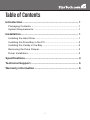
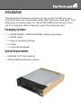
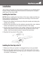
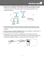
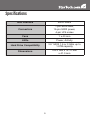
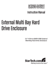
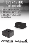
DRW150SAT
DRW150SATBK
Instruction Manual
Serial ATA Hard Drive Mobile
Rack Drawer
Aluminum 5.25” Rugged SATA
Hard Drive Mobile Rack Drawer
FCC Compliance Statement
This equipment has been tested and found to comply with the limits for a Class B digital
device, pursuant to part 15 of the FCC Rules. These limits are designed to provide
reasonable protection against harmful interference in a residential installation. This
equipment generates, uses and can radiate radio frequency energy and, if not installed
and used in accordance with the instructions, may cause harmful interference to radio
communications. However, there is no guarantee that interference will not occur in a
particular installation. If this equipment does cause harmful interference to radio or
television reception, which can be determined by turning the equipment off and on, the
user is encouraged to try to correct the interference by one or more of the following
measures:
• Reorient or relocate the receiving antenna.
• Increase the separation between the equipment and receiver.
• Connect the equipment into an outlet on a circuit different from that to which the receiver
is connected.
• Consult the dealer or an experienced radio/TV technician for help.
Use of Trademarks, Registered Trademarks, and other Protected Names and Symbols
This manual may make reference to trademarks, registered trademarks, and other
protected names and/or symbols of third-party companies not related in any way to
StarTech.com. Where they occur these references are for illustrative purposes only
and do not represent an endorsement of a product or service by StarTech.com, or an
endorsement of the product(s) to which this manual applies by the third-party company
in question. Regardless of any direct acknowledgement elsewhere in the body of
this document, StarTech.com hereby acknowledges that all trademarks, registered
trademarks, service marks, and other protected names and/or symbols contained in this
manual and related documents are the property of their respective holders.
Table of Contents
Introduction...................................................................... 1
Packaging Contents.....................................................................1
System Requirements..................................................................1
Installation........................................................................ 1
Installing the Hard Drive...............................................................1
Installing the Drive Bay in the PC.................................................2
Installing the Caddy in the Bay.....................................................3
Removing the Drive Drawer..........................................................3
Driver Installation..........................................................................3
Specifications................................................................... 4
Technical Support............................................................ 5
Warranty Information....................................................... 5
i
Introduction
The Mobile Rack Drawer consists of a bay portion that fits into your
5.25” drive bay and a removable caddy that holds your hard drive. This
allows you to quickly swap 3.5” Serial ATA (SATA) hard drives in and
out of a computer without having to open the computer case.
Packaging Contents
• 1 x DRW150SAT / DRW150SATBK mobile rack drawer
• 1 x SATA cable
• 1 x bag of mounting screws
• 2 x Keys
• 1 x Instruction Manual
System Requirements
• Available 5.25” bay opening
• SATA enabled computer system
1
Installation
This section will guide you through the installation of your Mobile Rack
Drawer. Please read through the instructions carefully and complete
each step in the order listed.
Installing the Hard Drive
NOTE: Before installing the hard drive in the case, make sure that you
have properly configured your hard drive according to the hard drive
manufacturer’s specifications.
1. Remove the caddy from the bay by lifting the handle and sliding the
caddy out of the bay.
2. Remove the top panel from the caddy by pressing the cover release
button and slide the cover towards the back of the caddy.
3. Gently place the hard drive in the caddy, making sure that the screw
holes on the bottom of the hard drive line up with the holes in the
caddy. Use the provided screws to secure the hard drive.
4. Replace the top panel of the caddy.
Installing the Drive Bay in the PC
1. Make sure that your system is unplugged and you are grounded.
2. Remove the side covers from your PC and remove the front cover
from an available 5.25” drive bay (see your computer’s user manual
for details, if necessary).
2
3. By default, the DRW150SAT/DRW150SATBK is configured for use
LED on it’s front panel. If you wish to use a different LED indicator,
move the switch on the rear panel to the rightmost position (as
illustrated below).
LED on/off
LP4 molex
switch
15-pin 7-pin
SATA SATA
power
4. Insert the bay into the 5.25” bay slot, making sure that the screw
holes on the side or bottom of the bay line up with the holes in the
bay slot.
5. Connect your computer’s SATA port to the connector on the back of
the bay with the included SATA cable.
6. Plug either an LP4 molex or SATA power connector from your
computer’s power supply into the power port on the back of the unit.
7. Using the supplied screws, securely mount the bay into the PC.
3
Installing the Caddy in the Bay
1. With the handle lifted, slide the caddy into the bay until it is firmly
seated. Lower the handle to click the caddy into its proper position.
2. Insert the key and turn clockwise to lock the drive into place and
supply the drive with power. The drive will not function if the drawer
has not been locked.
Removing the Drive Drawer
1. Insert the key and turn counter-clockwise to unlock the drive drawer.
2. Lift the handle and gently pull the caddy out of the bay.
NOTE: Do not unlock the drawer while the hard drive is in use. Only
power down the drive when the hard drive is idle. Once you have
powered down the hard drive, wait about 15 seconds to let the hard
drive “spin down” before removing the caddy from the bay.
Driver Installation
No driver installation is required as this is a passive device. Only the
hard drive itself is visible to the computer system.
4
Specifications
Bus Interface
SATA 3Gb/s
Connectors
7-pin SATA data,
15-pin SATA power,
4-pin LP4 molex
Fans
1 x 40 mm
LEDs
Power, Activity
Hard Drive Compatibility
3.5” SATA 1.5 or 3 Gb/s up to
1.5TB capacity
Dimensions
190.0 mm x 147.0 mm
x 41.0 mm
5
Technical Support
StarTech.com’s lifetime technical support is an integral part of our
commitment to provide industry-leading solutions. If you ever need
help with your product, visit www.startech.com/support and access
our comprehensive selection of online tools, documentation, and
downloads.
Warranty Information
This product is backed by a one year warranty.
In addition, StarTech.com warrants its products against defects in
materials and workmanship for the periods noted, following the initial
date of purchase. During this period, the products may be returned
for repair, or replacement with equivalent products at our discretion.
The warranty covers parts and labor costs only. StarTech.com does
not warrant its products from defects or damages arising from misuse,
abuse, alteration, or normal wear and tear.
Limitation of Liability
In no event shall the liability of StarTech.com Ltd. and StarTech.com USA
LLP (or their officers, directors, employees or agents) for any damages
(whether direct or indirect, special, punitive, incidental, consequential, or
otherwise), loss of profits, loss of business, or any pecuniary loss, arising
out of or related to the use of the product exceed the actual price paid
for the product. Some states do not allow the exclusion or limitation of
incidental or consequential damages. If such laws apply, the limitations
or exclusions contained in this statement may not apply to you.
6
StarTech.com has been making “hard-to-find easy” since 1985,
providing high quality solutions to a diverse IT and A/V customer
base that spans many channels, including government, education
and industrial facilities to name just a few. We offer an unmatched
selection of computer parts, cables, A/V products, KVM and Server
Management solutions, serving a worldwide market through our
locations in the United States, Canada, the United Kingdom and
Taiwan.
Visit www.startech.com today for complete information about all
our products and to access exclusive interactive tools such as the
Cable Finder, Parts Finder and the KVM Reference Guide.