1
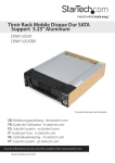
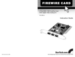
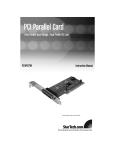
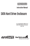
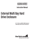
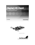
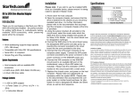
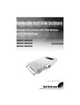
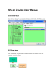
REMOVABLE SERIAL ATA DRIVE
DRAWER
5.25” Serial ATA Hard Drive Drawer
DRW150SAT
DRW150SATBK
Instruction Guide
* Actual product may vary from photo
* DRW150SAT shown
FCC COMPLIANCE STATEMENT
This equipment has been tested and found to comply with the limits for a Class B digital
device, pursuant to part 15 of the FCC Rules. These limits are designed to provide
reasonable protection against harmful interference in a residential installation. This
equipment generates, uses and can radiate radio frequency energy and, if not installed
and used in accordance with the instructions, may cause harmful interference to radio
communications. However, there is no guarantee that interference will not occur in a
particular installation. If this equipment does cause harmful interference to radio or
television reception, which can be determined by turning the equipment off and on, the
user is encouraged to try to correct the interference by one or more of the following
measures:
• Reorient or relocate the receiving antenna.
• Increase the separation between the equipment and receiver.
• Connect the equipment into an outlet on a circuit different from that to which the
receiver is connected.
• Consult the dealer or an experienced radio/TV technician for help.
1
Table of Contents
Introduction . . . . . . . . . . . . . . . . . . . . . . . . . . . . . . . . . . . . . . . . . . . . . . . . . . . . 2
Before You Begin . . . . . . . . . . . . . . . . . . . . . . . . . . . . . . . . . . . . . . . . . . . . . . . . 3
Installing the Hard Drive . . . . . . . . . . . . . . . . . . . . . . . . . . . . . . . . . . . . . . . . . . 4
Installing the Drive Bay . . . . . . . . . . . . . . . . . . . . . . . . . . . . . . . . . . . . . . . . . . . 5
Installing the Caddy . . . . . . . . . . . . . . . . . . . . . . . . . . . . . . . . . . . . . . . . . . . . . . 5
Removing the Drive Drawer . . . . . . . . . . . . . . . . . . . . . . . . . . . . . . . . . . . . . . . 5
Technical Specifications . . . . . . . . . . . . . . . . . . . . . . . . . . . . . . . . . . . . . . . . . . 6
Technical Support . . . . . . . . . . . . . . . . . . . . . . . . . . . . . . . . . . . . . . . . . . . . . . . 7
Warranty Information . . . . . . . . . . . . . . . . . . . . . . . . . . . . . . . . . . . . . . . . . . . . . 7
2
Introduction
Thank you for purchasing a StarTech.com 5.25” Serial ATA hard drive drawer. Now, you can quickly
add and remove hard drives from your system without having to open your computer. Each unit
consists of a bay portion that fits into your 5.25” drive bay and a removable caddy that holds your
hard disk. Whether for using multiple operating systems, making high speed, high capacity backups,
or minimizing downtime on mission-critical computers, StarTech.com’s removable drive drawers
provide the ultimate in reliability and convenience.
The DRW150SAT/DRW150SATBK uses a front caddy-mounted fan to provide a cooling air flow
system that keeps your hard drive at optimal temperatures. As well, DRW150SAT/DRW150SATBK
uses a sturdy aluminum caddy frame for extra durability.
Features
•
SATA to SATA interface
•
Point to point - free from master/slave setting
•
Locking mechanism controls power to the drive so that the disk cannot be accidentally removed
while in operation
•
Comes complete with a handy dust resistant cover panel that prevents dust particles from
entering your computer
•
The bay portion of the unit can be mounted from the bottom or the side
•
Supports Plug and Play installation and hot swapping
•
Backed by StarTech.com’s one year warranty
Before You Begin
To ensure a quick and easy drawer installation, please read through this section before attempting
your device.
WARNING: Hard drives require careful handling, especially when being transported. If you are not
careful with your hard disk, lost data may result. Always handle your hard drive and storage device
with caution. Hard drives, like all computer equipment can also be severely damaged by static
electricity. Be sure that you are properly grounded before opening your computer case or touching
any components. StarTech.com recommends that you wear an anti-static strap when installing any
computer equipment. If an anti-static strap is unavailable, discharge yourself of any static electricity
build-up by touching a large grounded metal surface (such as the computer case) for several
seconds. Do not bump, jar, or drop the device. Do not disconnect any cables or power sources
while the hard drive is active. This can result in data loss and possible damage to the hard drive.
Always make sure that your hard drive is fully spun down before removing the device.
System Requirements
• An IBM-PC or Mac computer with available 5.25” drive bay
3
Contents
•
1 x drive caddy
•
1 x drive bay
•
2 x Keys to lock/unlock the drive
•
1 x Bag of assorted screws
Installation
This section will guide you through the installation of your external drive case. Please read through
the instructions carefully and complete each step in the order listed.
Installing the Hard Drive
NOTE: Before installing the hard disk in the case, make sure that you have properly configured your
hard disk according to your hard disk manufacturer’s specifications.
1. Remove the caddy from the bay by lifting the handle and sliding the caddy out of the bay.
2. Remove the top panel from the caddy by pressing the cover release button and slide the cover
towards the back of the caddy.
3. Connect the caddy’s power connector to your hard drive’s power port.
4. Plug one end of the Serial ATA cable into an open port on your computer. Plug the other end into
the port on the case.
5. Gently place the hard drive in the caddy, making sure that the screw holes on the side or bottom
of the hard drive line up with the holes in the caddy.
6. Replace the top panel of the caddy.
*Note: Mount screws to underside of drawer
4
Installing the Drive Bay in the PC
1. Make sure that your system is unplugged and you are grounded.
2. Remove the side covers from your PC and remove the front cover from an available 5 1/4” drive
bay (see your computer’s user manual for details, if necessary).
3. a) By default, DRW150SAT/DRW150SATBK is configured for use with a SATA II drive. If you
wish to use a SATA (150) drive, move the switch on the rear panel to the rightmost position
(as illustrated below).
b) If you will be using a SATA (150) hard drive, please note that a connection must be made to
the motherboard in order to make use of the LED indicators on the host computer. Please
consult the documentation that was included with your motherboard/computer purchase to
determine individual connection requirements.
SATA/SATA II selector
LED pin connection to motherboard
DRW150SATBK - Rear Panel
3. Insert the bay into the 5 1/4” bay slot, making sure that the screw holes on the side or bottom of
the bay line up with the holes in the bay slot.
4. Connect your computer’s cable ribbon to the connector on the back of the bay.
5. Plug a connector from your computer’s power supply into the power port on the back of the bay.
6. Using the supplied screws, mount the bay into the PC.
Caddy
Bay
5 1/4” Bay
5
Installing the Caddy in the Bay
1. With the handle lifted, slide the caddy into the bay until it is firmly seated. Lower the handle to
click the caddy into its proper position.
2. Insert the key and turn clockwise to lock the drive into place and supply the drive with power.
The drive will not function if the drawer has not been locked.
Removing the Drive Drawer
1. Insert the key and turn counter-clockwise to unlock the drive drawer.
2. Lift the handle and gently pull the caddy out of the bay.
NOTE: Do not unlock the drawer when the hard drive is in use. Only power down the drive when
the hard drive is idle. Once you have powered down the hard drive, wait about 15 seconds to let the
hard drive “spin down” before removing the caddy from the bay.
6
Technical Specifications
Enclosure Dimensions
Length
W idth
Height
7.5 inches (190 mm)
5.8 inches (147 mm)
1.6 inches (41 mm)
Enclosure Construction
Aluminum
Hard Drive Compatibility
Compatible with 3.5” Serial ATA
Hard Drives
Data Transfer Rate
Up to 300 MBytes/sec.
Power
15 pin Serial ATA power connector
4 pin power connector
Safety Certifications
CE
Interface
Serial ATA 1.0
Front Fan
1.5 inches x 0.39 inches (40 mm x 10 mm)
7
Technical Support
The following technical resources are available for this StarTech.com product:
On-line help:
We are constantly adding new information to the Tech Support section of our web site. To access
this page, click the Tech Support link on our homepage, www.startech.com. In the tech support
section there are a number of options that can provide assistance with this product.
FAQ - This tool provides quick answers to the top questions asked by our customers.
Downloads - This selection takes you to our driver download page where you can
find the latest drivers for this product.
Support hours: Monday to Friday 9:00AM to 5:00PM EST (except holidays)
Warranty Information
This product is backed by a one-year warranty. In addition, StarTech.com warrants its products
against defects in materials and workmanship for the periods noted, following the initial date of
purchase. During this period, the products may be returned for repair, or replacement with equivalent
products at our discretion. The warranty covers parts and labor costs only. StarTech.com does not
warrant its products from defects or damages arising from misuse, abuse, alteration, or normal wear
and tear.
Limitation of Liability
In no event shall the liability of StarTech.com Ltd. and StarTech.com USA LLP (or their officers,
directors, employees or agents) for any damages (whether direct or indirect, special, punitive
incidental, consequential, or otherwise), loss of profits, loss of business, or any pecuniary loss,
arising out of or related to the use of the product exceed the actual price paid for the product.
Some states do not allow the exclusion or limitation of incidental or consequential damages. If such
laws apply, the limitations or exclusions contained in this statement may not apply to you.
Revised: April 10, 2007