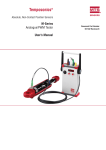
1
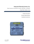
CB Button Gauge COMPLETE USER MANUAL By Chris Belcher CB BUTTON GAUGE 1 3 2 CB Digital-Lock Button Gauge & ‘Simplex Made Simple’ [P17] NOW Manipulating other Digital Locks [P16] [A Guide to Manipulating Simplex Digital Mechanical Locks] Forward I liken manipulating the Simplex Mechanical Digital Lock to that of picking a 5 Lever Mortice Lock, in that it has 5 Code Gears, each with a Gate. When picking a 5 Lever Mortice Lock, my aim is to align each Lever’s Gate with the BoltStump, when all the Lever’s Gates are in alignment with the Bolt-Stump – the bolt will be able to move to the open position. In picking 5 Lever Mortice Locks The Golden Rule is to only move that Lever which shows most resistance to moving and it is this Procedure which I am applying to the Simplex Mechanical Digital Lock. The Multi-Stump Slide [Unlocking Slide] is similar to a Multi-Stump Lock, and when we apply Tension to the Slide, one or more Stumps will make contact with its own Code Gear. We are able to detect which Code Gears are in the Code and which position they are in within the Code, as well as detecting when a Code Gears Gate is in alignment with its Stump. Chris Belcher Digital-Lock Button Gauge Handy Tool to Help Manipulate the Simplex Digital Locks Simplex Made Simple Use a Procedure Use Logic Pack consists of: 1 Button Gauge in Plastic Container CD with Instructions 2 3 4 CB.Button Gauge CB.Button Gauge Figure 1 On the internal of the Button Gauge is a Shaft which simply slides in and out of the Gauge Body, on the visible end of that Shaft there is a single Radial Indicator Line, this is a ‘guide’ to detect the amount of movement. What does it look like? Button Gauge Shaft Aluminium cylindrical shaped Gauge with an inner Shaft, with a Button on either end to prevent the Shaft and the Gauge Body from separating, see Figure 3 on this page Radial Indicator Lines Button Gauge Body Figure 2 What is it for? The Button Gauge will allow you to better judge the difference in depressed position of each button which can vary from lock to lock due to the wear and tear within the Lock / Buttons themselves. To enable the user to measure the position of a Button when it is depressed. [to see Depressed Positions see Chart on page 5 ] Chart for Buttons Figure 3 How does it work? Using light pressure place the Gauge over the Button depress the Button until it stops moving, the Button Gauge will indicate one of the 4 possible positions of a Button. [referred to as Depressed Positions, see Chart on page 5] Radial Indicator Lines Button Gauge Body Button 1 Button 1 2 Button 2 3 Button 3 4 Button 4 5 Button 5 The amount of difference in movement of each Button is quite small and for some it maybe difficult to differentiate, without some sort of gauge. Therefore, what appears to be a very simple little ‘widget’ is actually a very handy tool. 4 5 6 7 CB.Button Gauge Practical: This tool is to enable you to detect whether a Button Number is in the Code or not. It is to be used as a gauge, hence its name. ‘Simplex made Simple’ A little advice: I would advise anyone working through this ‘practical’, to take their time. It would be almost impossible to take this Guide to site for the 1st time, and expect to follow through the Procedure to manipulate a Simplex lock. This has been written in an effort to keep up with technology – we do not de-value technology by expecting to have a Instant 1-2-3 answer to overcoming such products – take your time to really understand this Procedure using this ‘practical’, and you should be able to use this method when needed. There should be enough information here to allow you to cope with most Codes without resorting to ploughing through hundreds of different permutations, please take note that the codes quoted in this ‘practical’ are for example purposes and the results of testing may differ from lock to lock. What is important, is the Procedure. Contents Prefix After decoding has started and either Button 1 is not in the Code or has been pressed and advanced to align its Gate, other Buttons may be tested [those that do not feel solid]. The Button Gauge is placed over the lock Button to be tested whilst applying light tension, the Shaft of the Button Gauge is gently pressed until the Shaft comes to a ‘Stop’ position [solid]. There is a single Radial Indicator Line on the Button Gauge Shaft which indicates whether a Button number is in the Code or not. To familiarize your-self with the difference between Depressed Position 2 & Depressed Position 3. Test the CB. Button Gauge on a Simplex Mechanical Digital Lock where the Manufacturers Code is set, ref Code 2 & 4 – 3. Apply tension and test Button 1 with the Button Gauge to see where the Radial Indicator Line comes to – this is Depressed Position 2. Repeat the same procedure for Button 5 to see where the Radial Indicator Line comes to – this is Depressed Position 3. Start [Idle] Position Depressed Position 1 Depressed Position 2 Depressed Position 3 Depressed Position 4 S 1 2 3 Section Section Section Section Section Section Section Section Section Section Section Section Section Section 4. Fully Depressed 4 Otherwise known as: Push Buttons/Buttons Half Number Function Code Gear Gears 2. ½ Depressed Travel then <<SOLID>> 6 1 2 3 4 5 6 7 8 1 2 3 4 5 6 Terminology: As said before, in this ‘practical’ Guide to manipulating the range of Simplex locks, we are approaching this in the same vein as manipulating a 5 Lever Mortice Lock, that means that we are using terminology similar to that within a mortice lock, if you are already accustomed to using Simplex terminology, the chart below contains some of the equivalent words. Also I have deliberately named the 3 sets of gears, to simplify the procedure. Chart for Depressed Positions 1. <<SOLID>> Part i Part i Part i Part i Part i Part i Part i Part i Part ii Part ii Part ii Part ii Part ii Part ii Suffix Forward to Guide , Index , Terminology Button Gauge Photo Breakdown of Code Chamber Colour Code Guide Identifying the Parts of the Code Chamber The Three Sets of Gears Charts for Step Changes Construction & Operation Tension & Pressure The Number 1 Code Gear Manipulate Simplex 1000 etc: Two number Code Manipulate Simplex 1000 etc: Three number Code Code Charts Manipulate Simplex 1000 etc: Double Press Manipulate Simplex 1000 etc: Five number Code Half Number Press Final Note & Permutation Table & Abbreviations 3. ¾ Depressed Travel then <<SOLID>> Unlocking Slide Unlocking Slide Toe Gear Pockets Here: Button Half Number Press Depressed Position Code Gear Common Gear Rail Primary Gear Primary Gear Cut-Away Multi Stump Slide Stump [Bolt Stump] Gate Contact Area for Button Plunger 7 8 Part i. Section 2. This Guide to Manipulating the Simplex Digital Mechanical Locks is Colour Coded. 9 Part i. Section 1 Photo Breakdown of Code Chamber Green represents the Three Sets of Gears – therefore the colour Green relates to these activities. Three Sets of Gears Example: Code Gear 1– Common Gear Rail– Primary Gear Gear 1. Code Gear Blue represents Buttons & Depressed Positions – therefore the colour Blue relates to these activities. Buttons & Depressed Positions – Example: Buttons Depressed Position 1 Red represents the Tension & Pressure – therefore the colour Red relates to these activities. 2. Contact Area for Button Plunger 3. Stump 4. Gate Tension & Pressure Example: Apply tension – using light pressure 5. Primary Gear Purple represents Logic – therefore the colour Purple relates to an activity when Logic is required or used. ◊ >>> Logic<< < Logic is concerned with WHAT is TRUE and HOW we can know whether something is TRUE. Black [bold] represents the Code numbers – therefore the colour Black relates to an activity when referring to the CODE itself. Code 8 6. Primary Gear CutAway 7. Multi Stump Slide 8. Common Gear Rail 9 10 11 Part i. Section 3 1 10 Identifying the Parts of the Code Chamber Name: Code Gear 2 Contact Area For Button Plunger. [when a Button is pressed it contacts this point on it’s Primary Gear] 3 Stump 4 Gate 5 Primary Gear 6 Primary Gear Cut-Away Firstly: Let’s look at these a little closer: Common Gear Rail Primary Gears Code Gears & MultiStump Slide Detail: 11 13 12 Part i. Section 4 The Three Sets of Gear Gears Part i. Section 5 Charts for Step Changes In Code 2–1–3– 4–5 Number Number Number Number Number 1. Primary Gear 2 1 3 4 5 Has Has Has Has Has 5 4 3 2 1 Step Changes Step Changes Step Chang�s Step Changes Step Changes 2 1 3 4 Has Has Has Has 4 3 2 1 Step Step Step Step In Code 2–1–3-4 2. Code Gears Number Number Number Number Changes Changes Changes Changes This is an important point to remember as it will tell us the position in the Code of the number we are working on. It will also help to determine double or triple pressed number Codes etc. 3. Common Gear Rail Explanation 1. Primary Gear Gears: The Primary Gears are moved by their own Button and are permanently engaged with their own Code Gears. Also a segment of each Primary Gear is removed in the area where it would otherwise be engaged with the Common Gear Rail, this prevents movement of the Gears if they are not in the Code. When a Button is depressed, the Primary Gear, firstly moves into engagement with the Common Gear Rail then advances the Common Gear Rail 1 Step Change. (Because of this there are two parts to this movement; the Code Gear has actually advanced/moved 2 Step Changes. This is only of interest if ½ Number Presses are used in the Code.) 2. Code Gears: Each Code Gear has a Gate which has to be aligned with its Stump (part of the Multi-Stump slide) and is driven initially by the Primary Gear, then, when another Button is depressed it will be advanced another single step change driven by the Common Gear Rail and its own Primary Gear. 3. Common Gear Rail: The Common Gear Rail connects each Code Gear into the chain when their Buttons have been depressed. Therefore in a Code of Codes: There are 5 Buttons numbered 1 to 5. A Code may consist of 1 number, 2 numbers, 3 numbers, 4 numbers or 5 numbers. A Code may also consist of double numbers where 2 numbers are pressed at the same time, e.g. You might want to input 2 sets of double numbers such as 2 & 4 - 1 & 5. A Code may consist of 1 triple number such as 1 & 2 & 3. A Code may consist of 1 quadruple number or if you have nimble fingers 5 numbers all at once. A Code may consist of ½ Number Presses. Notes: 1-2-3-4- 5 we are able say that Code Gear 1 is advanced not only by depressing Button , it is also advanced 1 Step Change for each of the subsequent Button presses. 12 13 14 15 Part i. Section 6 Section 7 Tension & Pressure Part i. Construction & Operation. Chart for Buttons 1 Button 1 2 Button 2 3 Button 3 4 Button 4 5 Button 5 There are: 5 Buttons One for each Code Gear. Each Button has 4 possible positions. Chart for Depressed Positions Start [Idle] Position Depressed Position 1 Depressed Position 2 Depressed Position 3 Depressed Position 4 S 1 2 3 Tension & Pressure Tension: In a 5 Lever Mortice Lock, one applies Tension on the Levers using a tension-wrench to pull back the Bolt Stump until it touches the Levers. With the Simplex mechanical digital locks such as the Simplex 7000 4 Depressed Position 1 or 900 we have a thumb turn which is effectively direct drive on the Multi Stump slide of the Code Chamber. When tested using light pressure, the Button moves a little against spring pressure then feels <<solid>>. This indicates a Button in the Code. Depressed Position 2 When tested using light pressure the Button moves about ½ its travel then feels <<solid>>, this indicates a Button not in the Code. This is because its Stump has engaged its Gate. Depressed Position 3 When tested with light pressure, the Button moves ¾ of its travel, this indicates a Code Gear which may or may not be in the Code, because its Stump is not in contact with its Code Gear, and is also the position used for Half Number Press Codes. Depressed Position 4 With the 1000 series etc we have a knob or handle, these locks incorporate a clutch between the handle and Multi Stump Slide of the Code Chamber. With direct drive, Tension is achieved by turning the thumb turn clockwise, only light Tension is required. If too much Tension is used more than more 1 Button will indicate as being <<SOLID>>. With those locks that have clutches there is little control, you have to turn the knob/handle clockwise/anti-clockwise depending on the variation of the product model [in the opening direction], just enough to apply Tension but not so much that the clutch slips. (this could be a bit tiresome) Is a Button fully depressed and its Code Gear has been advanced. 14 15 17 16 Part i. Further Uses For the CB Button Gauge: Section 8 The Number 1 Code Gear. Within the Code Chamber, the Code Gears are held in place by spacers incorporated into a pressed steel cage. The construction of the cage limits the amount of free axial movement of the Number 1 Code Gear so much so that when Tension is applied, the Multi Stump Slide only initially makes contact with the Number 1 Code Gear, therefore we always start the process by testing Number 1 Code Gear. This effect may not be present in all Code Chambers. Button has 3 lines to accommodate manipulating the Supra buttons. will usually be the 1st to indicate if it is in the Code. locks This effect is not present in the new 5000 series and will be dealt with in the next publication. Button info: Info: The button numbers in this practical correspond to the button numbers on the products. I 1 11 V V 11 1 16 Supra: Apply tension using the opening button, this allows you to measure the amount of movement on the buttons. There is a distinct difference in movement between those buttons that are in the code, and those buttons that are not in the code. The radial line that is nearest the top of the spindle [with the new blue button] is used for this purpose. The Button Gauge has been updated yet again. It now Keylex: To decode the Keylex, press all the buttons except the “C” button [Clear]. Now use the button gauge to measure each of the CODE buttons by depressing them lightly until they come to a STOP. Buttons that are NOT the CODE will stop moving when the top indicator line of the button gauge [nearest the blue button] just enters the spindle hole of the gauge, and will remain just visible. Those buttons that are in the code will travel further and the indicator line will disappear completely. Don’t forget to press the CLEAR button before you enter the code to OPEN the lock. I II III IV V 17 18 19 Part ii. Section 1 Part ii. Let’s Start to Manipulate the Simplex 1000 and similar locks with the same chamber. Example A. Section 2 Let’s Start to Manipulate the Simplex 1000 and similar locks with the same chamber. Example B. Code of 1 - 2 Code of 2 - 3 - 4 1 Apply Tension: Test all Buttons by attempting to depress each Button in turn using light Tension & Pressure only. What we are looking for is any Button that feels <<SOLID >> Sometimes 2 Buttons indicate. Choose the Button most resisting movement as the next Button to press, and the other Button as the test Button. 1 Apply 2 Button In this case: Button will feel <<SOLID >> (because it is not in the Code and its Gate is already aligned) Depressed Position 1 3 it is therefore in the Code. : Press Button Test remaining Buttons is <<SOLID >>. and Buttonsand depress to - - - they will depress to Depressed Position 3 indicating that the Number 1 Code Gear is not yet in position. We also now know that is not the last 1 number of the Code, (see Code charts Chapter ii Part 3) as it needs more than a 1 Step Change to align its Gate. Therefore to advance Number 1 Code Gear one further Step Change we press another Button. Tension ….. Button This means that Number 1 Code Gear One of the other Buttons will feel <<SOLID >>. In this case Button (this is a 1 Step Change of the Code Gear) Depressed Position 3 with Button being depressed to Depressed Position 2 4 has (not in Code, this tells us that there only 3 numbers in the Code) We now need to find the position of Number 2 Code Gear within the Code as Button felt <<SOLID >> therefore it is in the Code. advanced 2 Step Changes . In this case the lock will open when Tension is applied. Code is: 1 - 2 Release 18 will depress to Depressed Position 2 2 Release Press Tension: Test all Buttons by attempting to depress each Button in turn using light Tension & Pressure only. Tension ….. 19 21 20 Press 6 Apply Button Tension Test Buttons and and will depress to Depressed Position 3 5 We now know that Button is not the last number of the Code, because, if the Gate of Number 2 Code Gear had come into line, either or would feel <<SOLID >>, and Buttons that would mean that it only required 1 Step Changes to align its Gate, therefore we need to advance Number 2 Code Gear 1 Step Change (a total of 2 Step Changes). Release Press Apply Test Tension ….. Button 20 Button has to be the 1st number of the Code, this also tells us that there are no double or triple numbers in the Code because there are 3 numbers in the Code, and Number 2 Code Gear needed 3 Step Changes to align its Gate. If there had been a double number, then the maximum Step Changes any Code Gear could make, would be 2 in this instance. The reason is that double, triple or quadruple simultaneous presses are seen mechanically as a 1 Step Change. We now know that there are only three numbers in the Code and the 1st number is number Button 2-?-? . The other numbers are Buttons We could carry on decoding, it is not required in this case as there are only 2 possible combinations, and they are or Tension using light Tension & Pressure. Button will depress to Button Depressed Position 3 ◊ This means that Number 2 Code Gear’s Gate is still not aligned. Therefore, because we know that there are only 3 numbers in the Code:- Code of 2 - 3 - 4 Code of 2 - 4 - 3 Notes: >>> Now we will take a logical leap<< < This means that we are taking in the information which we have gleaned, and put it together to make certain deductions. 21 23 22 Part ii. CODE CHARTS Here are 4 charts which show the position in a Code of a given number, depending on how many Step Changes a Code Gear has to take to bring its Gate into alignment with its Stump. Number of Presses to Align Gate for 5 numbers in a Five Number Code Position In Code CODE CHARTS Position In Code CODE CHARTS Position In Code CODE CHARTS Position In Code Part ii. Section 3: Code Charts 1 1 2 3 4 5 2 X X 3 X 4 X 5 X Number of Presses to Align Gate for 4 numbers in a Four Number Code 1 2 3 4 1 X 2 X 3 X 4 X Let’s Start to Manipulate the Simplex 1000 and similar locks with the same chamber. Double Number Press : [indicated by the ‘&’ sign between 2 Button numbers] Example C. Apply 1 2 3 X 2 X Release Press Apply Test 1 2 1 X 2 X Tension and test all Buttons is <<SOLID >> – therefore, indicating Button that it is in the Code. Tension ….. Button Tension and - - -, Buttonshows to be <<SOLID >> therefore, [indicating that it is in the Code and Button is last Buttons Buttons - - all move to number of the Code.] 3 X Number of Presses to Align Gate for 2 numbers in a Two Number Code Code of 3 & 4 together then 1 & 2 together Number of Presses to Align Gate for 3 numbers in a Three Number Code 1 Section 4: Depressed Position 3 Release Press Apply Test Tension ….. Button Code Gear Tension and thenadvancing Number 2 - - all move to Buttons Depressed Position 3 NB. We could not test Button in its 1st position as Number 1 Code Gear was already located in that position Do not go on until you understand all of the previous process. It is important for the next process. The previous examples show how we find a number that is in the Code, and then advance its Code Gear one Step Change at a time to determine when its Gate is lined up with its Stump, this tells us the position in the Code; we have also found other numbers that are not in the Code by looking at how far a Button is depressed. 22 Depressed Position 1 Release Tension ….. 23 25 24 Press Apply Test Button Tension Therefore, not in the Code. This proves that the 1st Option was correct. - Buttons - have moved to You will note that Buttons Change each. Buttons &only had 1 Step ?-?-1&2- x Depressed Position 3 Release Press Apply Test Reset Press Tension ….. Button Tension Button Apply Test it has moved to Depressed Position 3 Reset Press Apply Test is doubled up with - Buttons& Buttons Buttons - - is <<SOLID >> Button therefore, is in the Code. Button moved to Buttons Therefore, may or may not be in the Code. Buttons is <<SOLID >> Button therefore, is in the Code. with 2 Step Changes is 2 Button Button nd This leaves the following permutations to test & together Depressed Position 3 -& ?-3-1&2 -x as a Double Number Press , or Button No 2 Option: is that it is the 1 st number of the Code. [by resetting - this action releases the Tension as well] We’ll start with No 1 Option and … Button Tension Buttons Tension from last number [Remember that a Double Number Press is seen mechanically as a Single Number. In this case 1 & 2 are both in the last number position.] [This means that we still have not found the No 2 Code Gear Gate position.] At this stage we have 2 Options. No 1 Option: is that Button [by resetting - this action releases the tension as well] & & && 3&4-1&2- x Notes: In the next Section of this ‘Practical’, all the ‘obvious’ actions have been removed , for example : Release tension / Apply tension etc etc. By this stage you should be well practiced with these procedures. Also the next Section of this ‘Practical’ will be using abbreviations. moved to Depressed Position 2 24 25 26 27 Part ii. Section 5 As there has been a change in state of number 5 it means that we have found the position of number 1 in the Code. It has been advanced 3 Step/C’s; therefore it is 3 rd number from last in the Code. We have to say this at this time because we do not yet know how many numbers in the Code. As number 1 is 3rd from last number in the Code and requires 3 Step/C’s to align its Gate, we must advance number 1 for all further tests, by 3 Step/C’s. The known Code thus far is ? - ? – 1 [3 Step/C’s] -? -?. Let’s Start to Manipulate the Simplex 1000 and similar locks with the same chamber. Example D. Code of 2 & 3 together and 1 – 4 – 5 By now, working through this ‘practical’, you have become accustomed to the value/meaning of certain part names and activities; you will find it quicker to use initials. See index below: Index Abbreviations Index Button Depressed Position 1 Number 1 Code Gear <<SOLID >> Step Change 1 Apply Test 2 Press Test DP/1 etc No 1 C/G <S> Step/C etc etc etc Test 26 4 Test Press Tension and test all B’s = <S>, therefore, is in the Code. Band B’s- - - all move to DP/3 to advance No 1 C/G B’s - - B - - and found B = as we know it is in the Code B’s - then B B (No 1 C/G has been advanced 3 Step/C’s and 5 by 1 Step/C) 5 Test to advance No 1 C/G one further Step/C B’s - B = <S> number 4 moves to DP/3 - = <S>and B moves to DP/3 B’s B Therefore, now we know that No 5 C/G only required 1 Step/C to align its Gate and is therefore, the last number in Code. The known Code thus far is : ? - 1 [3 Step/C’s] – ? - 5 [1 Step/C]. ?-?-1-?- 5 one further Step/C all move to DP/3 3 Press So far we pressed B’s: <S> etc B B Press ?-?-1-?- ? As B We do NOT test = <S>, it is in the Code, therefore, we find out where B is, in the Code. B at its 1 Step/C as No 5 C/G is already in the last B st position with 1 Step/C. 27 29 28 Press Test B’s No 1 C/G has advanced 3 Step/C’s, No 3 C/G has advanced 2 Step/C’s and No 5 C/G has advanced by 1 Step/C B’s both move toDP/3 This tells us that No 3 C/G is not aligned yet, having only been advanced by 2 Step/C’s. We cannot test it with 3 Step/C’s because No 1 C/G has already been advanced by 3 Step/C’s [already taking that position]. Therefore, we advance B to detect whether it is the 1st or 2nd number of the Code. 7 Press Test The only permutations left are: 1] & B’s B’s B’s B’s 2] 3] 4] & & & Code of 2 & 3 together and 1 – 4 – 5 -- and . B this shows <S> B’s Therefore, No 3 C/G required 4 Step/C’s to align its Gate and is 4th from last number in Code. NB. This also means that there can only be ONE Double Number Press number in this Code. The known Code thus far is : ? - 3 [4 Step/C’s] - 1 [3 Step/C’s] - ? - 5 [1 Step/C’s]. Part ii. Section 6 Half Number Press As mentioned before, Half Number Press’s may be used in the code. A Half Number Press is when a Button is moved to Depressed Position 3 when in-putting the code. ?-3-1-?- 5 This can be added to your manipulation procedure. We now need to find the position of number No 4 C/G in the Code. Reset Press Test - - - . B , and this shows to be <S> Therefore, B is in When testing the Buttons that are <<SOLID>>, test at Depressed Position 3 first, then test when fully depressed. B’s Notes: the Code. And No 4 C/G is in its correct position. Press B’s Try to open the lock – and in this instance it will not open, therefore, there must be a Double Number Press set of numbers in the Code, therefore, B one of the Double Number Press’s . 28 has to be 29 31 30 Suffix: The worst scenario is a 5 digit/number Code with no double or triple Codes, and the B or No 1 C/G is the first number of the Code. This Code is rather difficult to de-code because No 1 C/G will need 5 steps to place it in its Gate, leaving no Buttons to test. Therefore, you will know the 1st Code Number and it’s position, leaving you with having to try all the permutations of a 5 digit/number Code with number 1 always being the first number, see the chart following. There are 24. 12345 12543 13524 14523 14352 12534 13542 14532 14325 15224 12453 13452 13245 14235 15234 15423 12435 13425 13254 14253 15243 15432 Button 1 2 3 4 5 2nd from last 3rd from last 4th from last 5th from last TEST No? PRESS No? No ? SOLID 15342 12354 Abbreviations Index Numbers in the Code Position in the Code PB1 [PUSH BUTTON 1] ? PB2 ? PB3 ? last See Chapter ii Part 5 etc B Depressed Position 1 DP/1 etc Number 1 Code Gear <<SOLID >> Step Change No 1 C/G <S> Step/C etc etc etc Mark these empty grids to chart your findings: 30 31 CODE CHARTS Position In Code CODE CHARTS Position In Code CODE CHARTS Position In Code CODE CHARTS Position In Code Five Number Code Chart Number of Presses to Align Gate for 4 numbers in Code Four Number Code Chart Number of Presses to Align Gate for 3 numbers in Code Three Number Code Chart Number of Presses to Align Gate for 2 numbers in Code Two Number Code Chart 12345 12543 13524 14523 14352 12354 12534 13542 14532 14325 12453 13452 13245 14235 15234 12435 13425 13254 14253 15243 Mark this empty grid to chart your findings: 32 Number of Presses to Align Gate for 5 numbers in Code