1
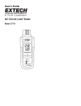
Integrated Metering Systems, Inc.
Models beginning
eginning with MS120S01, ES120S01, MD240S01,
MD240S01 & ED240S01
Single Meter Outdoor Units
Product Description
Technical Specifications
Installation Instructions
PN: 114-0002
Revision 3.0
Revision 3.0
MINI METER OR EE MODULE OUTDOOR INSTALLATION GUIDE
List of Figures ................................................................................................................................. 2
List of Tables .................................................................................................................................. 2
1. Product Description ................................................................................................................... 3
1.1 General Description............................................................................................................... 3
1.2 Meter Features ....................................................................................................................... 3
1.3 Meter Certifications............................................................................................................... 3
1.4 Physical Description .............................................................................................................. 3
1.4.1 Single Meter ................................................................................................................... 3
1.4.2 Enclosures....................................................................................................................... 4
1.5 Applications .......................................................................................................................... 5
2. Technical Specifications ............................................................................................................. 6
2.1 Model Number Description ................................................................................................... 6
2.1.1 Individual Meter Model Numbers .................................................................................. 6
2.1.2 Meter in Enclosure Model Numbers .............................................................................. 7
2.2 Electrical Specifications ........................................................................................................ 8
2.3 Input/Output Connections and User Display ........................................................................ 9
3. Installation Instructions ............................................................................................................. 11
3.1. Explanation of Warning Symbols ...................................................................................... 11
3.2 Safety Precautions ............................................................................................................... 11
3.3 Preparation .......................................................................................................................... 12
3.4 List of Materials .................................................................................................................. 12
3.5 Mounting the Enclosure ...................................................................................................... 12
3.5.1 Mounting Location ....................................................................................................... 12
3.5.2 Drilling Conduit Holes ................................................................................................. 13
3.5.3 Mounting Procedure and Conduit Installation ............................................................. 13
3.6 Installation of Voltage Lines ............................................................................................... 14
3.7 Variations and Installation of Current Transformers .......................................................... 14
3.8 Testing the Installation ........................................................................................................ 18
3.9 Securing the Enclosure ........................................................................................................ 18
4. Maintenance .............................................................................................................................. 18
5. Troubleshooting/FAQ .............................................................................................................. 19
6. Contact Information ................................................................................................................. 20
7. Returned Material Policy .......................................................................................................... 21
Integrated Metering Systems, Inc.
1
Table of Contents
Revision 3.0
MINI METER OR EE MODULE OUTDOOR INSTALLATION GUIDE
List of Figures
Figure 1: Single Mini Meter/EE Module case dimensions ............................................................. 4
Figure 2: Small enclosure outline and mounting dimensions ......................................................... 5
Figure 3: Mini Meter model number format ................................................................................... 6
Figure 4: New enclosure model number format ............................................................................. 7
Figure 5: Mini Meter connections and display ............................................................................... 9
Figure 6: Mounting the enclosure ................................................................................................. 13
Figure 7: IMS solid core CTs........................................................................................................ 15
Figure 8: IMS split core CTs ........................................................................................................ 15
Figure 9: Mini Meter or EE Module hookup diagram .................................................................. 17
List of Tables
Table 1: Electrical and environmental specifications ..................................................................... 8
Table 2: I/O connections ............................................................................................................... 10
Table 3: Display indicators ........................................................................................................... 10
Integrated Metering Systems, Inc.
2
List of Figures
Revision 3.0
MINI METER OR EE MODULE OUTDOOR INSTALLATION GUIDE
1. Product Description
1.1 General Description
The IMS Mini Meter is a self-powered, current transformer (CT) rated electronic
kilowatthour (kWh) meter designed for permanent connection to an electrical service.
Mini Meters come in single element (2-wire) and dual element (3-wire) configurations.
This guide is for use with the single unit outdoor enclosure.
1.2 Meter Features
•
•
•
•
•
•
•
Revenue-grade accuracy with solid-core or easy to install split core CTs
Built in LCD or external mechanical counter
Multiple load monitoring with a single meter
Encapsulated model for harsh environments (model number prefixes EE)
AMR compatible isolated pulse outputs
Reverse-phase LED indicator
10-year warranty
1.3 Meter Certifications
•
•
•
•
•
UL Listed (100A & 200A models only) for use in the US or Canada
Conforms to accuracy requirements set forth in ANSI C12.1
Certified to California Division of Measurement Standards
Approved by the California Energy Commission for use in the California Solar
Initiative’s Performance Based Incentive Program
Approved by State of Maryland Public Service Commission in accordance with
applicable ANSI C12.1 requirements
1.4 Physical Description
1.4.1 Single Meter
Figure 1 on the following page shows the dimensions of a single Mini Meter or
EE Module case and cover.
Integrated Metering Systems, Inc.
3
1.1 Product Description
Revision 3.0
MINI METER OR EE MODULE OUTDOOR INSTALLATION GUIDE
Figure 1: Single Mini Meter/EE Module case dimensions
1.4.2 Enclosures
Mini Meter and EE Module small enclosures are manufactured by Bud Industries,
Inc. (www.budind.com). The outline and mounting drawing for the small
enclosure is shown below in Figure 2. More detailed specification sheets are
available from the Bud website, part number NBB-15240.
Integrated Metering Systems, Inc.
4
1.4 Product Description
Revision 3.0
MINI METER OR EE MODULE OUTDOOR INSTALLATION GUIDE
Figure 2: Small enclosure outline and mounting dimensions
1.5 Applications
•
•
•
Apartments
Marinas
Mobile Home Parks
Integrated Metering Systems, Inc.
•
•
5
Campgrounds
Anywhere accurate electric submetering is
needed
1.5 Product Description
Revision 3.0
MINI METER OR EE MODULE OUTDOOR INSTALLATION GUIDE
2. Technical Specifications
2.1 Model Number Description
2.1.1 Individual Meter Model Numbers
The Mini Meter model number format is shown below and in Figure 3. The
breakdown of the model number is as follows:
Figure 3: Mini Meter model number format
1. MM indicates a Mini Meter Product; EE denotes epoxy encapsulated versions
2. Meter configuration
S – Single Element Meter
D – Dual Element Meter
3. Rated Voltage (L1 or L2 to Neutral)
4. CT Ratio
1001 – 100:0.1
2001 – 200:0.1
2002 – 200:0.2
4001 – 400:0.1
5. Outputs
T – Provided with 0.1 kWh and 0.01 kWh isolated outputs and 0.1 kWh counter
output
Blank – Provided with 1.0 kWh, 0.1 kWh, and 0.01 kWh isolated outputs and 1.0
kWh counter output
6. Counter
SCC – Self Contained Counter (built-in LCD)
Blank – Not provided
Integrated Metering Systems, Inc.
6
2.1 Technical Specifications
Revision 3.0
MINI METER OR EE MODULE OUTDOOR INSTALLATION GUIDE
2.1.2 Meter in Enclosure Model Numbers
Enclosure model numbers were recently changed to supply more precise
information. The old model number (MMD or MMS – PKG – O) has been
replaced with the format shown in Figure 4.
Figure 4: New enclosure model number format
1. Meter Type
MS – Single Element Mini Meter (1-phase, 2-wire)
MD – Dual Element Mini Meter (1 or 2-phase, 3-wire)
ES – Single Element EE module (1-phase, 2-wire)
ED – Dual Element EE module (1 or 2-phase, 3-wire)
2. Voltage
120 – 120V (1-phase, 2-wire) (Single Element only)
240 – 240V (1 or 2-phase, 3-wire) (Works with 208V applications as well)
For Single Element Models (MS and ES), 1PH 2W: Voltage rating is Phase-toNeutral
For Dual Element Models (MD and ED), 1PH 3W, 2PH 3W: Voltage rating is
Phase-to-Phase
3. Enclosure Size
S – Small outdoor enclosure
4. Number of Meters Enclosed
5. Counter Type
MO – Mechanical 1 kWh
TO – Mechanical 1/10 kWh
SO – Self-contained LCD
XO – No Counter
6. CT Ratio
011 – 100:0.1
021 – 200:0.1
022 – 200:0.2
044 – 400:0.1
7. Additional Options
00 – No Options
Integrated Metering Systems, Inc.
7
2.1 Technical Specifications
Revision 3.0
MINI METER OR EE MODULE OUTDOOR INSTALLATION GUIDE
2.2 Electrical Specifications
Mini Meters and EE Modules fall under UL Circuit Category III: a device for
measurements performed in the building installation. The electrical specifications for
Mini Meters are given in the table below.
Input Configurations
1 Phase, 2 wire
1 or 2 Phase, 3 wire
Supply Voltage Range
(L1 or L2 to Neutral)
Min. 102 VAC
Max. 138 VAC
Maximum Input Power, L1 and L2
8 VA
Maximum Rated Current1
440 A primary for 400 A models
220 A primary for 200 A models
110 A primary for 100 A models
0.11 A secondary for 0.1 A secondary models
0.22 A secondary for 0.2 A secondary models
Line Frequency
50-60 Hz
Power Factor Range
0.5 to 1.0, leading or lagging
Accuracy
+/- 0.5% of registration @ 1.0pf. 2 to 200 A
+/- 0.75% of registration @ 0.5pf, 2 to 200 A
Operating Temperature Range
-30 to +60 degrees C
Rated Pollution Degree2
2
Rated Relative Humidity
80%
Terminal Blocks:
Dinkle/International Connector
EK508-11P or equiv.
4.4 in-lb of torque maximum
Table 1: Electrical and environmental specifications
1
Product approved for use with included IMS Current Transformers, as follows:
400A: Part number CT400148SO or CT400148SO-1.5 or CT400148SP-142
200A: Part number CT200124XX or CT200148XX or CT200148XXSO-0.72 or CT200148SP-095
100A: Part number CT100124XX or CT100148XX or CT100148XXSO-0.72 or CT100148SP-095
2
Pollution Degree 2: Normally only non-conductive pollution occurs. Occasionally, however, a temporary
conductivity caused by condensation must be expected.
Integrated Metering Systems, Inc.
8
2.2 Technical Specifications
Revision 3.0
MINI METER OR EE MODULE OUTDOOR INSTALLATION GUIDE
2.3 Input/Output Connections and User Display
Figure 5: Mini Meter connections and display
Voltage Inputs (wire connections)
Description
L1
Black wire, voltage input, Line 1, 120V with
respect to neutral
N
White wire, Neutral input
L2
Red wire, voltage input, Line 2, 120V with
respect to neutral (MMD and EED models
only)
CT Inputs
CT1 : X1
Current Transformer input, CT1. Colored wire
of CT1
CT1 : X2
Current Transformer input, CT1. White wire
of CT1
CT2 : X1
Current Transformer input, CT2. Colored wire
of CT2 (MMD and EED models only)
CT2 : X2
Current Transformer input, CT2. White wire
of CT2 (MMD and EED models only)
Integrated Metering Systems, Inc.
9
2.3 Technical Specifications
Revision 3.0
MINI METER OR EE MODULE OUTDOOR INSTALLATION GUIDE
Outputs
10, Isolated Output (10 Wh/P, Kh = 10)
Isolated pulse output: 5 watthours on, 5
watthours off, referenced to ISOL COM
NOT TO BE USED FOR FIELD WIRING
100, Isolated Output (100 Wh/P, Kh=100)
Isolated pulse output: 50 watthours on, 50
watthours off, referenced to ISOL COM
1000, Isolated Output (1 kWh/P, Kh=1000)
Isolated pulse output: 500 watthours on, 500
watthours off, referenced to ISOL COM (not
available on models with T suffix)
ISOL COM
Isolated common for 10/100/1000 isolated
outputs
Counter (kh = 100 or kh = 1000)*
For 12 VDC electro-mechanical counter
Counter (kh = 100 or kh = 1000)*
For 12 VDC electro-mechanical counter
+12 VDC
(MMS and MMD models only)
12 VDC output; current rating is 3 mA max.
Table 2: I/O connections
*Recommend IMS counter #521-001 (1 kWh models), #512-002 (0.1 kWh models), or equivalents
LED Indicators
Description
Power LED (green)
Illuminates when the meter is supplied with
proper voltage
Load LED (green)
50% duty cycle (at constant load) LED to
verify proper meter function when connected
to a load. At 200 watts, LED will illuminate
for 1.5 minutes, then turn off for 1.5 minutes;
with no load, LED will remain on or off
Reverse Phase LED (red)
Illuminates when a problem with meter
phasing exists. With no load, LED may be on
or off. See section 3.7 for CT installation
instructions
LCD Display
Optional LCD display that shows total kWh
Table 3: Display indicators
Integrated Metering Systems, Inc.
10
2.3 Technical Specifications
Revision 3.0
MINI METER OR EE MODULE OUTDOOR INSTALLATION GUIDE
3. Installation Instructions
The following section contains installation and wiring instructions for the IMS Mini
Meter or EE Module in a single meter outdoor enclosure. If technical assistance is required at
any point during the installation, contact information can be found at the end of this manual.
IMS is not responsible for damage to the meter caused by incorrect wiring.
3.1. Explanation of Warning Symbols
Indicates the need to consult the operation manual due to the
presence of a potential risk.
Indicates the presence of electric shock hazards. Prior to
proceeding, de-energize the circuit and consult the operation
manual.
Indicates that the equipment is protected throughout by
double insulation.
3.2 Safety Precautions
WARNING
•
Installation of electric meters requires working with possibly hazardous voltages.
These instructions are meant to be a supplement to aid trained, qualified
professionals.
•
Turn off all power supplying the equipment before performing any wiring
operations. Use a properly rated voltage sensing device to confirm power is off.
•
Installations should be done in accordance with local codes and current National
Electric Code requirements.
•
Equipment used in a manner not specified by this document impairs the protection
provided by the equipment.
Failure to follow these warnings could result in serious injury or death.
Integrated Metering Systems, Inc.
11
3.0 Installation Instructions
Revision 3.0
MINI METER OR EE MODULE OUTDOOR INSTALLATION GUIDE
3.3 Preparation
1. Verify the model number and electrical specifications of the device being installed to
confirm they are appropriate for the intended electrical service (see Section 2).
2. Consult local codes for any possible permits or inspections required before
beginning electrical work.
3. Ensure the conduit for the installation is flexible and non-metallic. For outdoor
applications conduit and conduit fittings must be rated for UL Type 4X outdoor
enclosures. Failure to use the appropriate conduit impairs the degree of equipment
protection.
4. Make sure all tools to be used during installation have proper insulation ratings.
5. Look at the meter and inside the electrical panel for possible exposed wire, broken
wire, damaged components or loose connections.
3.4 List of Materials
•
•
•
•
Mini Meter or EE Module small enclosure and associated mounting materials.
Line 1, Line 2, and Neutral hook-up wires as needed for the electrical service. Wires
must be 18 AWG or larger and insulated for 300 VAC min.
Current Transformers (CTs): This product is designed for use with IMS CTs; see
Section 2.2 for details.
Flexible, non-metallic conduit and fittings; UL Type 4X for outdoor applications.
3.5 Mounting the Enclosure
3.5.1 Mounting Location
•
•
•
•
•
Meter installations require a switch or circuit breaker as part of the building
installation.
The switch or circuit breaker must be marked as the disconnecting device for
the meter.
It is recommended that the enclosure be mounted near the disconnecting
device in an area with adequate ventilation.
The enclosure should not be positioned in a manner that makes it difficult to
operate the disconnecting device.
Ensure that the CT and voltage lead lengths (and conduit lengths) are capable
of reaching the enclosure from the load center.
Integrated Metering Systems, Inc.
12
3.3 Installation Instructions
Revision 3.0
•
MINI METER OR EE MODULE OUTDOOR INSTALLATION GUIDE
If a suitable mounting location near the load center cannot be found,
additional in-line fuses or circuit breaker may be required in accordance with
NEC regulations.
3.5.2 Drilling Conduit Holes
The bottom panel and lower half of the side panels work best for conduit opening
locations in outdoor single meter enclosures. Select the location the makes wire
installation easiest for the given environment. If the side panels are used, holes
should be centered approximately half an inch from the bottom of the enclosure.
Hole sizes must be appropriate to fittings, and large enough to fit all voltage and
CT wiring (4-7 18 AWG min. wires insulated for 300 V min.). Care should be
exercised to keep drill bit away from components inside the enclosure. Type 4X
conduit and fittings must be used in order to maintain the outdoor rating of
the enclosure.
3.5.3 Mounting Procedure and Conduit Installation
1. Attach the mounting brackets to the back of the enclosure with the four
provided screws as shown in Figure 6.
2. Fasten the enclosure to the selected surface via mounting holes.
3. Verify that the enclosure is not loose and that all connections are secure.
4. Attach the conduit between enclosure and load center, routing wires as
necessary for later use.
5. Make sure the conduit fittings are aligned properly and tightened securely to
prevent moisture from entering the enclosure (outdoor applications).
Figure 6: Mounting the enclosure
Integrated Metering Systems, Inc.
13
3.5 Installation Instructions
Revision 3.0
MINI METER OR EE MODULE OUTDOOR INSTALLATION GUIDE
3.6 Installation of Voltage Lines
Check to make sure service is disconnected before any connections are
made.
1. Field wired voltage connections are made to the Mini Meter terminal block. The rated
torque for these terminal blocks is 4.4 in-lb, and can be used with solid and stranded
copper wires, at 12-18 AWG.
2. Verify that branch circuit fuse specifications meet local electric codes. (See section
2.2).
3. Connect 18 AWG min., 300 V min. insulated wiring for Line voltages and Neutral to
the appropriate locations in the breaker panel, in accordance with all national and
local electrical codes; see Figure 9 for wiring diagram.
4. Route wires through the conduit if not already done.
5. Trim the wire to the appropriate length to avoid coils of excess wiring.
6. Strip wiring to approximately .300 inches if needed and connect to the appropriate
terminals. Wires should be tightened so that they are held snuggly in place, but do
not to over-tighten, as this may compress and weaken the conductor
3.7 Variations and Installation of Current Transformers
To reduce risk of electric shock, always open or disconnect the
circuit from the power distribution system of a building before
installing or servicing current transformers.
In accordance with NEC, CTs may not be installed in any panel board
where they exceed 75% of the wiring space of any cross-sectional area.
General Requirements:
•
•
•
•
Splices on the CT leads must be within the meter enclosure, not inside the conduit. IMS
provided CT leads are 24 inches minimum. Wire insulation should be stripped so that the
bare conductor length that connects to the meter terminal block does not exceed 0.300
inches.
CTs should be securely fastened such that they will not slide down to live terminals.
Wires should be tightened so that they are held snuggly in place, but do not to overtighten, as this may compress and weaken the conductor.
Current and voltage inputs must be installed ‘in phase’ for accurate readings (e.g. CT1 on
Line 1, CT2 on Line 2); see Figure 9.
Integrated Metering Systems, Inc.
14
3.6 Installation Instructions
Revision 3.0
MINI METER OR EE MODULE OUTDOOR INSTALLATION GUIDE
CT Variations
•
IMS solid core CTs (Figure 7): In accordance with CT label, the LINE side of CT
must face incoming Line. White lead connects to X2 of CT connection (CT1:X2 or
CT2:X2). Colored lead connects to X1 of the corresponding CT connection (CT1:X1
or CT2:X1).
Figure 7: IMS solid core CTs
Installing solid core CTs
1.
2.
3.
4.
5.
Route CT wires through the conduit if not already done.
Trim the wire to the appropriate length to avoid coils of excess wiring.
At MMU, strip insulation from wires to approximately .300 inches.
Connect CT leads to the appropriate meter as described above.
With power turned off, disconnect each monitored conductor and slide on a CT,
ensuring the CT is correctly oriented as noted above.
6. Reconnect the conductors.
•
IMS split core CTs (Figure 8): The side with the white dot, H1, must face the
incoming LINE. White wire connects to X2 terminal, black wire connects to X1
terminal.
Figure 8: IMS split core CTs
Integrated Metering Systems, Inc.
15
3.7 Installation Instructions
Revision 3.0
MINI METER OR EE MODULE OUTDOOR INSTALLATION GUIDE
Installing split core CTs
1.
2.
3.
4.
5.
Route CT secondary wires through conduit if not already done.
Trim the wire to the appropriate length to avoid coils of excess wiring.
Strip wiring to approximately .300 inches.
Connect the CT leads to the appropriate meter as described above.
With power to the conductors turned off, place one CT around each conductor,
ensuring that the white dot is facing the line side.
Failure to install CTs in the correct orientation and on the correct phase will lead to
inaccurate meter readings. Figure 9 shows a wiring diagram for Mini Meters and EE
Modules.
Integrated Metering Systems, Inc.
16
3.7 Installation Instructions
Revision 3.0
MINI METER OR EE MODULE OUTDOOR INSTALLATION GUIDE
Figure 9: Mini Meter or EE Module hookup diagram
Integrated Metering Systems, Inc.
17
Hookup Diagrams
Revision 3.0
MINI METER OR EE MODULE OUTDOOR INSTALLATION GUIDE
3.8 Testing the Installation
Testing Voltage
The power LED illuminates when the Mini Meter or EE Module has a proper power
supply. Voltage should also be tested using an AC Voltmeter to verify that the voltage
across voltage line terminals (L1 to Neutral and L2 to Neutral) is not in excess of the
maximum rated voltage in section 2.2.
CT Reverse Phase Indicator
Mini Meters and EE Modules have a red reverse phase indicator LED as described in
section 2.3. There must be a load drawing a minimum of 1 A connected to the meter
in order for the reverse phase LED to function correctly. If a proper load is
connected, and the LED is illuminated, power down the voltage supply and verify that
CTs are installed correctly.
Load LED
The load LED is described in section 2.3. This LED should be cycling at 50% duty cycle
when the meter is connected properly and a constant load is applied.
3.9 Securing the Enclosure
In accordance with safety requirements, enclosures must be secured using the provided
key lock once installation is complete. The purpose of the lock is to prevent access to live
parts that pose potential safety risks. To install the lock, slide through the provided holes
on the clamp side of the enclosure and fasten securely.
4. Maintenance
Properly installed meters with sound connections and secure conduit fittings should not
require user maintenance. If the meter is functioning abnormally, consult the
FAQ/Troubleshooting guide. If the answer cannot be found there, contact IMS technical
support (see Section 6).
Integrated Metering Systems, Inc.
18
3.8 Installation Instructions
Revision 3.0
MINI METER OR EE MODULE OUTDOOR INSTALLATION GUIDE
5. Troubleshooting/FAQ
Problem
Solution
1. Power LED not illuminated
•
•
•
2. Load LED not flashing
•
•
•
3. Registered consumption low
•
•
•
•
4. Counter isn’t incrementing
•
•
Check to make sure all connections are
wired according to section 3.6
Test the voltage being supplied to the meter
using an AC voltmeter
With power off, remove any additional line
fuses and test with ohmmeter
Verify CT connections and orientations
(see Section 3.7)
Make sure there is sufficient load to draw a
significant current (~1 A)
Test the voltage being supplied to the meter
using an AC voltmeter
Check to make sure the reverse phase LED
is not on.
Even if the reverse phase LED is off,
double-check CT orientations. One CT
installed in the incorrect direction doesn’t
always illuminate the reverse phase LED.
Make sure that current and voltage
connections are in phase (see Sections 3.6
and 3.7)
Check power connections and fuses
Verify the Load LED is working
On Mini Meters, verify that counter wires
are connected to COUNTER terminals
FAQ
Q: Can you use additional sets of current transformers (CT’s) with a submeter to
accommodate more circuits?
A: Yes, you can use up to three sets of CT’s in parallel per meter. Just make sure you do not
exceed the current rating per phase. Consult IMS technical support for more information (see
Section 6).
Q: What is AMR equipment?
A: AMR is Automatic Meter Reading equipment. This typically consists of radio transmitters,
repeaters and a collector that monitors, records, and is capable of transmitting data to a third
party billing service (RBC).
Integrated Metering Systems, Inc.
19
5.0 Troubleshooting/FAQ
Revision 3.0
MINI METER OR EE MODULE OUTDOOR INSTALLATION GUIDE
Q: Why are the current transformers color coded (Black & white, red & white, and blue &
white)?
A: CT1 needs to monitor the same phase used to power the meter on line 1, CT2 needs to
monitor the same phase used to power line 2. Color coding helps the installer maintain correct
phasing.
Q: I accidentally installed my CTs backwards; can I switch the X1 and X2 terminal
connections instead of flipping the CT?
A: Meters are tested and approved for accuracy with CTs installed in the correct orientation.
Installing CTs backwards and inverting the terminal connections has a slight affect on meter
accuracy.
Q: Can the meters be tampered with after installation?
A: All of the IMS meter enclosures provide a loop for padlocks or other tamper evident
equipment. The displays are all non-resettable.
Q: Can voltage input wires and current transformer secondary leads be routed through the
same conduit?
A: Yes, provided you are using IMS supplied CTs. Alternate CTs must have a 0.1 A max
secondary rating and 18 AWG min. wires with at least 300 VAC insulation rating.
Q: Can digital output wires be routed through the same conduit as voltage input and
current sensing wires?
A: No. In accordance with NEC and UL requirements, Class 2 wiring (digital outputs) must be
separated from Class 1 wiring.
Q: I still can’t get my meter to work, what now?
A: Contact technical support via phone or on our website given in the following section.
6. Contact Information
Integrated Metering Systems, Inc.
11701 S. Belcher Rd., Suite 123
Largo, FL 33773
Phone: 727-539-1813
Toll Free: 800-488-3594
On the web: http://www.imsmeters.com/
Integrated Metering Systems, Inc.
20
5.0 Troubleshooting/FAQ
Revision 3.0
MINI METER OR EE MODULE OUTDOOR INSTALLATION GUIDE
7. Returned Material Policy
After acceptance, all sales of meters are final. IMS, in its sole discretion, authorizes product
returns in appropriate circumstances, subject to such conditions as IMS may specify. Any such
return is subject to the express prior authorization and approval of IMS. Buyer must notify IMS
at 800-488-3594 (telephone) or 727-539-1984 (fax) and request a Returned Material
Authorization Number (RMA Number) and state the specific reason for return. Unauthorized
returns will not be accepted.
When requesting an RMA Number please supply the following information:
1. Distributors name and address
2. Model number of meter
3. Original purchase order number
4. Reason for return
All paperwork and boxes must be marked with an RMA number issued by IMS. All authorized
returned materials must be shipped freight prepaid to IMS to the address specified below. IMS is
not responsible for uninsured packages or packages lost by your carrier.
Integrated Metering Systems (IMS)
11701 S Belcher Rd., Suite 123
Largo, FL 33773
All returns are subject to a handling/restocking charge, except for product shipped in error or
products under warranty. All charges (modification, repair, restock etc) related to returned
products will be determined by IMS upon evaluation. All shipping costs are the responsibility of
the buyer.
METERS RETURNED FOR CREDIT*
Replacement meter ordered
0% Restock Charge
• RMA Number requested by stocking distributor for credit must be
accompanied by a purchase order for material of equal or greater value.
NO replacement meter ordered
25% Restock Charge
METERS RETURNED FOR REPAIR (STILL UNDER WARRANTY)*
No defects found
$75.00 evaluation charge
Defects not covered under warranty
Charges upon evaluation
Defects found covered under warranty
No Charge
METERS RETURNED FOR EVALUATION (NO LONGER UNDER WARRANTY)*
Evaluation charge of $75.00 applies
Other charges will apply depending on evaluation by IMS
*Prices are as of May 01, 2009 and subject to change
Integrated Metering Systems, Inc.
21
7.0 RMA Policy
Revision 3.0
MINI METER OR EE MODULE OUTDOOR INSTALLATION GUIDE
8. Revision History
Revision
2.2
2.3
Date
19 Feb 2009
17 Mar 2009
Changes
Initial Release to UL
Revised with changes from UL
Added new enclosure model numbers
Changes Figure/Table linking
Removed transmitter installation
Added section 3.9: Securing the Enclosure
Changed “NEMA” to “UL Type”
Removed IMS CT open circuit protection wording
Removed reference to metallic conduit
2.5
18 May 2009
3.0
22 May 2009
Stylistic Changes
Added double insulation symbol and RMA page
Final Review Changes and Production Release
Integrated Metering Systems, Inc.
22
8.0 Revision History