1
PC208 DATALOGGER SUPPORT SOFTWARE
INSTRUCTION MANUAL
REVISION: 11/97
COPYRIGHT (c) 1987-1997 CAMPBELL SCIENTIFIC, INC.
This is a blank page.
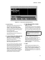
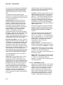
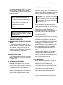
CR10X USERS!
The following steps explain how to convert a CR10 program to a CR10X program. This will allow you to
use the CR10X specific options and instructions within the program. You only need to do this once for
each existing program. New programs will use the CR10X templates when you select the CR10X
datalogger type.
1. Using the new EDLOG, load the existing CR10 program. Notice the datalogger caption, in the top
right portion of the screen, reads “CR10".
2. Locate the text “;{CR10}“ on the first line of the file.
3. Edit the text so it reads “;{CR10X}”.
4. Save (or Save As) the file and then close it. Do not compile the program.
5. Load the file you just saved. Notice that the datalogger caption, in the top right corner of the screen,
now reads “CR10X”.
The saving, closing, and loading of the file is critical as it changes the associated template from the
CR10 template to the CR10X template. Please do not skip any steps.
If the CR10 program was created with a version of EDLOG less then 6.0, you will need to use the
DOC2CSI utility before doing the steps given above. The PC208 manual Section 9 gives more
information on using DOC2CSI.
Thank You.
This is a blank page.
LIMITED WARRANTY
CAMPBELL SCIENTIFIC, INC. warrants that the magnetic diskette on which the accompanying
computer software is recorded and the documentation provided with it are free from physical
defects in materials and workmanship under normal use. CAMPBELL SCIENTIFIC, INC.
warrants that the computer software itself will perform substantially in accordance with the
specifications set forth in the Operator’s Manual published by CAMPBELL SCIENTIFIC, INC.
CAMPBELL SCIENTIFIC, INC. warrants that the software is compatible with IBM PC/XT/AT and
PS/2 microcomputers and 100% compatible computers only. CAMPBELL SCIENTIFIC, INC. is
not responsible for incompatibility of this software running under any operating system other than
those specified in accompanying data sheets or operator’s manuals.
The above warranties are made for ninety (90) days from the date of original shipment.
CAMPBELL SCIENTIFIC, INC. will replace any magnetic diskette or documentation which proves
defective in materials or workmanship without charge.
CAMPBELL SCIENTIFIC, INC. will either replace or correct any software that does not perform
substantially according to the specifications set forth in the Operator’s Manual with a corrected
copy of the software or corrective code. In the case of significant error in the documentation,
CAMPBELL SCIENTIFIC, INC. will correct errors in the documentation without charge by
providing addenda or substitute pages.
If CAMPBELL SCIENTIFIC, INC. is unable to replace defective documentation or a defective
diskette, or if CAMPBELL SCIENTIFIC, INC. is unable to provide corrected software or corrected
documentation within a reasonable time, CAMPBELL SCIENTIFIC, INC. will either replace the
software with a functionally similar program or refund the purchase price paid for the software.
CAMPBELL SCIENTIFIC, INC. does not warrant that the software will meet licensee’s
requirements of that the software or documentation are error free or that the operation of the
software will be uninterrupted. The warranty does not cover any diskette or documentation which
has been damaged or abused. The software warranty does not cover any software which has
been altered or changed in any way by anyone other than CAMPBELL SCIENTIFIC, INC.
CAMPBELL SCIENTIFIC, INC. is not responsible for problems caused by computer hardware,
computer operating systems or the use of CAMPBELL SCIENTIFIC, INC.’s software with nonCAMPBELL SCIENTIFIC, INC. software.
ALL WARRANTIES OF MERCHANTABILITY AND FITNESS FOR A PARTICULAR PURPOSE
ARE DISCLAIMED AND EXCLUDED. CAMPBELL SCIENTIFIC, INC. SHALL NOT IN ANY
CASE BE LIABLE FOR SPECIAL, INCIDENTAL, CONSEQUENTIAL, INDIRECT, OR OTHER
SIMILAR DAMAGES EVEN IF CAMPBELL SCIENTIFIC HAS BEEN ADVISED OF THE
POSSIBILITY OF SUCH DAMAGES.
CAMPBELL SCIENTIFIC, INC. is not responsible for any costs incurred as result of lost profits or
revenue, loss of use of the software, loss of data, cost of re-creating lost data, the cost of any
substitute program, claims by any party other than licensee, or for other similar costs.
LICENSEE’S SOLE AND EXCLUSIVE REMEDY IS SET FORTH IN THIS LIMITED WARRANTY.
CAMPBELL SCIENTIFIC, INS.’S AGGREGATE LIABILITY ARISING FROM OR RELATING TO
THIS AGREEMENT OR THE SOFTWARE OR DOCUMENTATION (REGARDLESS OF THE
FORM OF ACTION - E.G. CONTRACT, TORT, COMPUTER MALPRACTICE, FRAUD AND/OR
OTHERWISE) IS LIMITED TO THE PURCHASE PRICE PAID BY THE LICENSEE.
LICENSE FOR USE
This software is protected by both the United States copyright law and international copyright
treaty provisions. You may copy it onto a computer to be used and you may make archival copies
of the software for the sole purpose of backing-up CAMPBELL SCIENTIFIC, INC. software and
protecting your investment from loss. All copyright notices and labeling must be left intact.
This software may be used by any number of people, and may be freely moved from one
computer location to another, so long as there is no possibility of it being used at one location
while it’s being used at another. The software, under the terms of this license, cannot be used by
two different people in two different places at the same time.
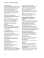
85
1
W. 18
00 N.
Logan, UT 4
2
3
81-18
4
USA
Phone (4
) 5
5
3
3
-23
2
4
Campbell Scientific Canada Corp.
115
4
6
-14
9th Street
Edmonton, Alberta T5
M 1W
CANADA
Campbell Scientific Ltd.
Campbell Park
Hathern Road
Shepshed Leics LE12 9RP
PC208 DATALOGGER SUPPORT SOFTWARE
TABLE OF CONTENTS
PAGE
INTRODUCTION
I.1
SOFTWARE OVERVIEW ......................................................................................................... 1
I.2
DISKETTES............................................................................................................................... 1
I.3
INSTALLATION ......................................................................................................................... 1
I.4
SOFTWARE INTEGRATION .................................................................................................... 2
I.5
INTRODUCTION TO USER INTERFACE ................................................................................ 4
1.
PC208E
1.1
PC208E .................................................................................................................................. 1-2
1.2
STATIONS AND SCHEDULES .............................................................................................. 1-2
1.3
1.3.1
1.3.2
1.3.3
1.3.4
1.3.5
1.3.6
1.3.7
1.3.8
STATIONS.............................................................................................................................. 1-2
Main Screen ........................................................................................................................... 1-2
Creating a New Station File .................................................................................................... 1-3
Making a Station Active .......................................................................................................... 1-3
Editing an Existing Station File ............................................................................................... 1-3
Monitor Mode(s) ..................................................................................................................... 1-4
Setting/Checking the Datalogger Clock.................................................................................. 1-4
Sending and Receiving Datalogger Program (DLD) Files ...................................................... 1-4
Data Collection (Single Station).............................................................................................. 1-4
1.4
1.4.1
1.4.2
1.4.3
1.4.4
1.4.5
1.4.6
1.4.7
1.4.8
SCHEDULES.......................................................................................................................... 1-5
Station File Compatibility ........................................................................................................ 1-5
Creating a Schedule ............................................................................................................... 1-5
Making a Schedule Active ...................................................................................................... 1-5
Editing an Existing Schedule .................................................................................................. 1-5
Creating a Station File or Adding Scheduling Information to an Existing Station File ............ 1-6
Station Files Other than Datalogger Station Files .................................................................. 1-6
Answering Incoming Calls ...................................................................................................... 1-6
Wait Option............................................................................................................................. 1-7
1.5
COLLECTING DATA FROM ONE OR MORE STATIONS ON DEMAND ............................. 1-7
1.6
THE VIEW AND DISPLAY MAIN MENU OPTIONS .............................................................. 1-7
1.7
HELP ...................................................................................................................................... 1-7
1.8
TELCOM AND GT COMPATIBILITY ..................................................................................... 1-8
1.9
DATA COLLECTION DIFFERENCES ................................................................................... 1-8
i
PC208 DATALOGGER SUPPORT SOFTWARE TABLE OF CONTENTS
2.
EDLOG
2.1
EDLOG INTRODUCTION ...................................................................................................... 2-1
2.2
OVERVIEW ............................................................................................................................ 2-2
2.2.1 Menu Description.................................................................................................................... 2-2
2.2.2 Creating/Editing Edlog Programs ........................................................................................... 2-3
2.3
2.3.1
2.3.2
2.3.3
PROGRAM DEVELOPMENT................................................................................................. 2-3
Entering Comments................................................................................................................ 2-3
Instructions ............................................................................................................................. 2-3
Expressions ............................................................................................................................ 2-4
2.4
2.4.1
2.4.2
2.4.3
2.4.4
2.4.5
2.4.6
EDITING EDLOG PROGRAMS ............................................................................................. 2-5
Editor Keystrokes ................................................................................................................... 2-5
Editing Comments, Instructions, and Expressions ................................................................. 2-6
Cut, Copy, Paste, and Clipboard Options............................................................................... 2-6
Using Library Files .................................................................................................................. 2-6
Renumbering the Instructions................................................................................................. 2-7
Compress View Option........................................................................................................... 2-7
2.5
INPUT LOCATIONS ............................................................................................................... 2-7
2.5.1 Entering Input Locations......................................................................................................... 2-7
2.5.2 Reps ....................................................................................................................................... 2-8
2.6
WINDOWS ........................................................................................................................... 2-10
2.7
2.7.1
2.7.2
2.7.3
INDENTION.......................................................................................................................... 2-10
Manual Indention .................................................................................................................. 2-10
Automatic Indention.............................................................................................................. 2-10
Rebuild Indention.................................................................................................................. 2-10
2.8
2.8.1
2.8.2
2.8.3
2.8.4
2.8.5
2.8.6
FILE TYPES ......................................................................................................................... 2-11
Files with a *.CSI Extension.................................................................................................. 2-11
Files with a *.DLD Extension ................................................................................................ 2-11
Files with a *.PTI Extension.................................................................................................. 2-11
Files with a *.FSL Extension ................................................................................................. 2-11
Files with a *.PDF Extension ................................................................................................ 2-11
Files with a *.LBR Extension................................................................................................. 2-11
3.
GRAPHTERM
3.1
3.1.1
3.1.2
3.1.3
3.1.4
3.1.5
3.1.6
STATION FILE ....................................................................................................................... 3-1
Datalogger Type ..................................................................................................................... 3-1
Asynchronous Communications Adapter ............................................................................... 3-2
Communication Baud Rate..................................................................................................... 3-2
Data File Format..................................................................................................................... 3-2
Final Storage Collection Area ................................................................................................. 3-2
Interface Device...................................................................................................................... 3-2
3.2
3.2.1
3.2.2
3.2.3
3.2.4
3.2.5
3.2.6
3.2.7
3.2.8
3.2.9
3.2.10
GRAPHTERM OPTIONS ....................................................................................................... 3-3
Call Station ............................................................................................................................. 3-3
T - Terminal Emulator............................................................................................................. 3-4
D - Download Program to Datalogger .................................................................................... 3-4
S - Save Program from Datalogger ........................................................................................ 3-4
K - PC Time to Datalogger Clock ........................................................................................... 3-4
P - Create Power-up PROM ................................................................................................... 3-5
M - Monitor Input Locations .................................................................................................... 3-5
U - Collect Uncollected Data .................................................................................................. 3-5
E - Exit Station Parameters .................................................................................................... 3-5
V - View Graphics File ............................................................................................................ 3-5
ii
PC208 DATALOGGER SUPPORT SOFTWARE TABLE OF CONTENTS
3.2.11 Q - Quit ................................................................................................................................... 3-5
3.3
3.3.1
3.3.2
3.3.3
3.3.4
3.3.5
3.3.6
3.3.7
3.3.8
MONITORING AND GRAPHING INPUT DATA..................................................................... 3-6
Locations ................................................................................................................................ 3-6
F1..F8 Flag Set....................................................................................................................... 3-6
D - Digits Displayed ................................................................................................................ 3-6
T - Terminal Emulator............................................................................................................. 3-6
Port Toggle ............................................................................................................................. 3-6
Input Value Load .................................................................................................................... 3-6
Collect Data ............................................................................................................................ 3-7
Sound ..................................................................................................................................... 3-7
3.4
3.4.1
3.4.2
3.4.3
3.4.4
3.4.5
3.4.6
3.4.7
3.4.8
3.4.9
3.4.10
3.4.11
3.4.12
G - GRAPHICS MODE ........................................................................................................... 3-7
H - Helps Show/Remove ........................................................................................................ 3-7
G - Graph Enter/Exit ............................................................................................................... 3-7
R - Re-Scale ........................................................................................................................... 3-7
+ - Increment Fixed Scale ...................................................................................................... 3-7
- - Decrement Fixed Scale...................................................................................................... 3-7
D - Digits Displayed ................................................................................................................ 3-7
L - L (Graph Specification Screen) ......................................................................................... 3-7
V - View Save to File .............................................................................................................. 3-8
F1..F8 Flag Toggle ................................................................................................................. 3-9
P1..P8 Toggle Ports ............................................................................................................... 3-9
C - Collect Data ...................................................................................................................... 3-9
W - Sweep graph Toggle........................................................................................................ 3-9
3.5
3.5.1
3.5.2
3.5.3
COMMAND LINE PARAMETERS.......................................................................................... 3-9
Additional Options .................................................................................................................. 3-9
Sending Text ........................................................................................................................ 3-10
Changing Station and Time Limits ....................................................................................... 3-10
4.
SPLIT
4.1
OVERVIEW ............................................................................................................................ 4-1
4.2
GETTING STARTED.............................................................................................................. 4-1
4.3
4.3.1
4.3.2
4.3.3
4.3.4
4.3.5
4.3.6
4.3.7
4.3.8
SPLIT PARAMETER FILE ENTRIES ..................................................................................... 4-1
Name(s) of Input Data File(s) ................................................................................................. 4-1
Name of Output File to Generate ........................................................................................... 4-3
START Reading in.................................................................................................................. 4-5
STOP Reading in.................................................................................................................... 4-7
COPY from ............................................................................................................................. 4-8
SELECT element #(s) in......................................................................................................... 4-8
HEADINGS for report: .......................................................................................................... 4-18
Headings for column # ......................................................................................................... 4-18
4.4
HELP OPTION ..................................................................................................................... 4-18
4.5
EDITING COMMANDS......................................................................................................... 4-18
4.6
COMMAND MENU ............................................................................................................... 4-19
4.7
COMMAND LINE ENTRIES ................................................................................................. 4-20
iii
PC208 DATALOGGER SUPPORT SOFTWARE TABLE OF CONTENTS
5.
TELCOM
5.1
STATION PARAMETERS ...................................................................................................... 5-2
5.2
STATION OPTIONS............................................................................................................... 5-8
5.3
5.3.1
5.3.2
5.3.3
SCRIPT FILES ....................................................................................................................... 5-9
Attended Operation ................................................................................................................ 5-9
Unattended Operation ............................................................................................................ 5-9
RF Networks........................................................................................................................... 5-9
5.4
5.4.1
5.4.2
5.4.3
5.4.4
RUNNING TELCOM UNATTENDED ................................................................................... 5-10
The Done (/D) Option ........................................................................................................... 5-10
The Wait (/W) Option ........................................................................................................... 5-10
Answering Incoming Calls /A............................................................................................... 5-10
The Autoexec.Bat File .......................................................................................................... 5-12
5.5
UNATTENDED USER PROGRAMS .................................................................................... 5-12
5.6
WAKETIME .......................................................................................................................... 5-13
6.
SMCOM
6.1
GETTING STARTED.............................................................................................................. 6-1
6.2
6.2.1
6.2.2
6.2.3
6.2.4
6.2.5
6.2.6
6.2.7
6.2.8
6.2.9
6.2.10
6.2.11
6.2.12
SMCOM OPTIONS................................................................................................................. 6-1
T - Terminal Emulator............................................................................................................. 6-1
A - Collect All Data Files ......................................................................................................... 6-2
U - Collect Uncollected Data Files.......................................................................................... 6-2
N - Collect Newest Data File .................................................................................................. 6-2
L - Collect One Data File Starting at Display Pointer.............................................................. 6-2
P - Collect Program Files........................................................................................................ 6-2
D - Store a .DLD Program File ............................................................................................... 6-2
F - Store a File........................................................................................................................ 6-2
E - Erase and Reset Storage Module..................................................................................... 6-2
C - Clear Data Storage ........................................................................................................... 6-2
S - Switch Settings.................................................................................................................. 6-3
Q - Quit ................................................................................................................................... 6-3
6.3
NAMING OF DATA FILES ON DISK...................................................................................... 6-3
6.4
6.4.1
6.4.2
6.4.3
6.4.4
6.4.5
DATA COLLECTION FORMATS ........................................................................................... 6-3
F - Final Storage..................................................................................................................... 6-3
D - ASCII Arrays with Element IDs ......................................................................................... 6-3
C - Comma Delineated ASCII Arrays ..................................................................................... 6-3
A - As Stored 8 Bit .................................................................................................................. 6-4
P - As Stored Strip Parity ....................................................................................................... 6-4
6.5
SMCOM COMMAND LINE PARAMETERS ........................................................................... 6-4
6.6
SMCOM COMMAND LINE SWITCHES................................................................................. 6-4
6.6.1 Sending Text .......................................................................................................................... 6-4
7.
CSMCOM
7.1
INSTALLATION ...................................................................................................................... 7-1
7.2
GETTING STARTED.............................................................................................................. 7-1
7.3
MENU OPTIONS.................................................................................................................... 7-1
7.3.1 T -- Terminal Emulator ........................................................................................................... 7-1
7.3.2 A -- Collect All Data Files........................................................................................................ 7-2
iv
PC208 DATALOGGER SUPPORT SOFTWARE TABLE OF CONTENTS
7.3.3
7.3.4
7.3.5
7.3.6
7.3.7
7.3.8
7.3.9
7.3.10
7.3.11
U -- Collect Uncollected Data Files......................................................................................... 7-2
N -- Collect Newest Data File ................................................................................................. 7-2
L -- Collect One Data File Starting at a Specified Location .................................................... 7-2
P -- Collect All Program Files ................................................................................................. 7-2
D -- Store a .DLD Program File .............................................................................................. 7-2
F -- Store a File....................................................................................................................... 7-3
E -- Erase, Reset and Test the Card ...................................................................................... 7-3
C -- Clear Data Area Quickly .................................................................................................. 7-3
Q -- Quit.................................................................................................................................. 7-4
7.4
FILENAME CONVENTIONS .................................................................................................. 7-4
7.5
DATA FILE FORMAT OPTIONS............................................................................................ 7-4
7.6
7.6.1
7.6.2
7.6.3
7.6.4
7.6.5
ADDITIONAL INFORMATION ON CSMCOM OPERATION ................................................. 7-5
Reading Data From More Than One Card ............................................................................. 7-5
Aborting Options..................................................................................................................... 7-5
Communication Errors............................................................................................................ 7-5
Battery Voltage Warnings....................................................................................................... 7-5
Card Errors ............................................................................................................................. 7-5
7.7
COMMAND LINE PARAMETER ............................................................................................ 7-6
7.7.1 Additional Command Line Parameter Options ....................................................................... 7-6
8.
SMCREAD
8.1
GETTING STARTED.............................................................................................................. 8-1
8.1.1 Installation .............................................................................................................................. 8-1
8.1.2 Running SMCREAD ............................................................................................................... 8-1
8.2
8.2.1
8.2.2
8.2.3
8.2.4
8.2.5
8.2.6
8.2.7
8.2.8
8.2.9
8.2.10
8.2.11
MENU OPTIONS.................................................................................................................... 8-1
T -- Terminal Emulator ........................................................................................................... 8-1
A -- Read All Data Files .......................................................................................................... 8-2
U -- Reads Unreads Data Files .............................................................................................. 8-2
N -- Read Newest Data File.................................................................................................... 8-2
L -- Read One Data File Starting At a Specified Location ...................................................... 8-2
P -- Read All Program Files.................................................................................................... 8-2
D -- Store a .DLD Program File .............................................................................................. 8-2
E -- Erase, Reset and Test the Card ...................................................................................... 8-3
C -- Clear Data Area Quickly .................................................................................................. 8-3
S -- Show the Position and Size of the Files in the Card ........................................................ 8-3
Q -- Quit.................................................................................................................................. 8-4
8.3
FILE NAME CONVENTIONS ................................................................................................. 8-4
8.4
8.4.1
8.4.2
8.4.3
DATA FILE FORMAT OPTIONS............................................................................................ 8-4
D -- Printable ASCII Data with IDs.......................................................................................... 8-4
C -- Comma Delineated ASCII Arrays .................................................................................... 8-5
A -- As Stored (8-Bit Data)...................................................................................................... 8-5
8.5
8.5.1
8.5.2
8.5.3
8.5.4
8.5.5
ADDITIONAL INFORMATION ON SMCREAD OPERATION................................................ 8-5
Reading Data From More Than One Card ............................................................................. 8-5
Aborting Options..................................................................................................................... 8-5
Battery Voltage Warnings....................................................................................................... 8-5
Card Errors ............................................................................................................................. 8-5
Running SMCREAD Under Windows 3.1............................................................................... 8-6
8.6
COMMAND LINE PARAMETERS.......................................................................................... 8-6
8.6.1 Additional Command Line Parameter Options ....................................................................... 8-7
v
PC208 DATALOGGER SUPPORT SOFTWARE TABLE OF CONTENTS
9.
DOC2CSI UTILITY .............................................................................................................. 9-1
APPENDIXES
A.
A.1
A.2
A.3
B.
B.1
B.2
B.3
C.
C.1
C.2
C.3
C.4
C.5
D.
D.1
E.
E.1
E.2
E.3
E.4
F.
F.1
F.2
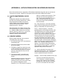
APPLICATIONS NOTES ON INTERFACE DEVICES
HAYES SMARTMODEM 1200 OR 300..................................................................................A-1
GENERIC MODEM ................................................................................................................A-1
MODEM INITIALIZATION FILE..............................................................................................A-3
USE OF COM3 OR COM4
PC208 AND COM3 AND COM4.............................................................................................B-1
PC208 AND THE PC201 CARD.............................................................................................B-1
PS/2 COMPUTERS AND PC208 ...........................................................................................B-1
PC208 ERROR MESSAGES
PC208E/GRAPHTERM ERROR MESSAGES .......................................................................C-1
SPLIT ERROR MESSAGES ..................................................................................................C-1
SMCOM ERROR MESSAGES...............................................................................................C-2
PC208E/TELCOM ERROR MESSAGES ...............................................................................C-3
SMCREAD ERROR MESSAGES ..........................................................................................C-4
EXPRESSION ERRORS
ERROR CODES AND MESSAGES .......................................................................................D-1
PCMCIA DRIVER SOFTWARE NOTES
GENERAL ..............................................................................................................................E-1
LOADING THE DRIVERS ......................................................................................................E-1
ADJUSTING YOUR CARDSERVICES SET-UP ....................................................................E-2
USING MEMMAKER (SUPPLIED WITH MS-DOS 6.XX) ......................................................E-3
FREQUENTLY ASKED QUESTIONS
PC208E.EXE .......................................................................................................................... F-1
EDLOG.EXE........................................................................................................................... F-1
TABLES
I-1
4.3-1
4.3-2
4.3-3
4.3.4
4.3-5
5-1
5-2
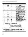
A-1
B-1
File Types Used with PC208 Software ...................................................................................... 3
Printable ASCII, Comma Delineated and Field Formatted Input File Format Types.............. 4-2
Input File Options ................................................................................................................... 4-2
Output Options ....................................................................................................................... 4-3
Definition of BLANK or Bad Data for each Data File Format.................................................. 4-4
Effect of Out of Range Values for Given Output Options ....................................................... 4-9
Files Created and Used by TELCOM ..................................................................................... 5-2
TELCOM Editing Commands ................................................................................................. 5-3
SMARTMODEM Configuration Switches ...............................................................................A-2
COM PORT Addresses and PC201 Card Settings ................................................................B-1
vi
PC208 DATALOGGER SUPPORT SOFTWARE TABLE OF CONTENTS
FIGURES
I-1
1.3-1
1.3-2
1.4-1
1.4-2
1.5-1
2.5-1
Menu Selection.......................................................................................................................... 4
Main Screen ........................................................................................................................... 1-2
Station File Editor ................................................................................................................... 1-3
Schedule Editor ...................................................................................................................... 1-5
Station File Editor Used with Schedule Editor ........................................................................ 1-6
Collect Now From Multiple Stations........................................................................................ 1-7
Input Location Editor Screen .................................................................................................. 2-9
vii
PC208 DATALOGGER SUPPORT SOFTWARE TABLE OF CONTENTS
This is a blank page.
viii
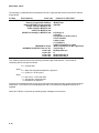
PC208 INTRODUCTION
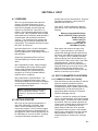
I.1 SOFTWARE OVERVIEW
The PC208 software package consists of
several separate packages.
PC208E provides computer / datalogger
communication for data collection and real-time
data display. In addition, it provides tools for
setting the datalogger clock, transferring
datalogger programs, and testing
communication links. PC208E can also act as
a starting place to access the other software
programs.
EDLOG is used to create and edit datalogger
programs on the PC. Compiled programs may
then be transferred to the datalogger over a
telecommunication link using PC208E. EDLOG
editing provides extensive help, cut and paste,
algebraic expressions, and syntax checking.
SPLIT processes selected data from a data file
or several data files and combines the data into
a report file. The value of each selected
element can be checked and flagged if it is out
of range. The report file may be given a
heading and labels for each column of data.
SPLIT allows the user to output the report file to
disk, printer or both. The report file is
compatible with popular spreadsheet programs.
SPLIT processes data produced by the CR21,
21X, CR7, CR7X and CR10(X).
SMCOM, CSMCOM, and SMCREAD provide
storage module support including data retrieval,
datalogger program transfer, resetting /
clearing, and setting of options. SMCOM works
with sealed canister modules, CSMCOM works
with card storage modules, and SMCREAD
accesses PCMCIA memory cards directly on a
computer equipped with a PCMCIA slot.
TELCOM collects data from Campbell Scientific
dataloggers over phone, RF and hard wire
interfaces. Datalogger type, interface options
and baud rate are specified by the user and
saved in a parameter file which may be used by
TELCOM or GraphTerm for auto dialing.
GraphTerm provides computer/datalogger
communication for real time display and
collection of data and downloading/uploading of
datalogger programs. Datalogger type,
interface options and baud rate are specified by
the user and saved in a parameter file which
may be used by GraphTerm or TELCOM for
auto dialing.
VS1 is used to add voice synthesizer (model
VS1) support to a datalogger program. VS1 is
distributed with the voice synthesizer hardware
not with PC208.
SHORT CUT is an alternative to EDLOG for
creating datalogger programs. Short Cut
guides users through the creation of simple
datalogger programs for standard
meteorological or hydrological sensors. Short
Cut is used to select sensors, choose output
data, create wiring diagrams, and generate
reports files. Short Cut supports the CR10(X)
and 21X datalogger. Short Cut is not distributed
with PC208 but is available at no cost from
Campbell Scientific.
DOC2CSI is a simple utility that converts
datalogger programs created with EDLOG 5.4
(.DOC files) to the format used by EDLOG 6.2
or newer (.CSI files). The .CSI file is created in
the current directory.
I.2 DISKETTES
PC208 is shipped on 3 1/2 inch high density
diskettes.
I.3 INSTALLATION
The PC208 software is installed by running
INSTALL.EXE on DISK 1 of the distribution
diskette(s). For example, to install with the
distribution diskette in the A drive:
A:INSTALL
The install program will prompt for the
dataloggers support by EDLOG. Help and
template file will only be installed for the
selected datalogger types. The install program
will also prompt for the installation of the
optional parts of PC208; Graphterm, SMCOM,
DOC2CSI, CSMCOM, SMCREAD, and SPLIT.
Most Graphterm features are present in
PC208E.EXE, which is automatically installed.
Graphterm retains compatibility with previous
versions for command line capability. SMCOM
1
PC208 INTRODUCTION
is only required if SM192 or SM716 solid state
storage modules are used. SPLIT is used for
additional processing of datalogger data.
CSMCOM and SMCREAD are used with the
MCR1 or CSM1 Card Storage Modules. All of
these programs are described in this manual.
The install program will prompt for a destination
directory for the PC208 files. This directory will
be created if it does not exist. The default
directory is \PC208E.
The install program will check if the selected
destination directory is part of the DOS PATH
statement. If it is not found, the install program
will optionally modify the AUTOEXEC.BAT file,
adding the directory to the PATH. Before any
changes are made, the existing
AUTOEXEC.BAT file will be copied to a file
named AUTOEXEC.CSI.
Any previous versions of the PC208 programs
will be overwritten if they are in the destination
directory. Install will prompt before overwriting
an existing MODEM.INI file as it may contain
custom modem strings.
NOTE: If this version of PC208 is installed
in the same directory as a previous version,
the old copy of SPLIT (Versions 4.8 and
earlier) will not be overwritten. The PC208
installation program will rename the existing
SPLIT.COM file to SPLIT.OLD. The
SPLIT.OLD file and the 5 overlay files;
SPLIT.000, SPLIT.001, SPLIT.002,
SPLIT.003, SPLIT.004 can be manually
deleted as they are not used. This version
of PC208 uses SPLIT in the form of
SPLIT.EXE.
Complete installation requires about 3
megabytes of free disk space.
PC208 requires 640K of conventional memory.
450K of conventional memory must be free to
2
run EDLOG or PC208E. 500K of memory must
be free to use the graphical monitor mode.
Memory can be freed by removing memory
resident programs. Later versions of DOS,
version 5 and 6, allow use of extended memory
for some DOS functions freeing some
conventional memory.
If there is insufficient memory or disk space a
warning will be displayed by the installation
software.
I.4 SOFTWARE INTEGRATION
Default extension names are assigned to files
generated by the PC208 DATALOGGER
SUPPORT SOFTWARE. Table I-1
summarizes these extensions.
For example, a field station "LOGAN" could be
called LOGAN and the software would add the
appropriate extension name depending on the
function to be completed. When many files are
stored bearing the same root name, the DOS
command DIR (i.e., 'DIR LOGAN.*') may be
used to obtain a directory of these files.
All PC208 functions can be accessed from
PC208E. For example, the user could:
1. Start EDLOG to create the datalogger
program.
2. Set up the station-link to the datalogger
program.
3. Set datalogger clock.
4. Transfer datalogger program to datalogger.
5. View real time measurements.
6. Retrieve data.
7. Start SPLIT to create reports.
PC208 INTRODUCTION
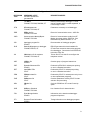
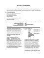
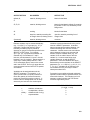
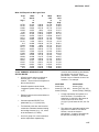
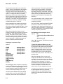
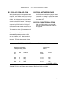
TABLE I-1. File Types Used With PC208 Software
EXTENSION
TYPE
MNEMONIC of EXT.
and SOFTWARE that
generated file
DESCRIPTION/USES
.DAT
raw DATa
PC208E, TELCOM, SMCOM, GT
Data as received from datalogger. Format
can be Printable ASCII, comma separated, or
Final Storage Format.
.STN
STatioN parameter
PC208E, TELCOM, GT
Parameters necessary to call datalogger.
.ERR
ERRor log file
PC208E, TELCOM
Record of communication errors. ASCII file.
.CQR
Communication Quality Report
PC208E, TELCOM
Record of communication quality from RF
Modem shut down blocks, ASCII file. See
Radiotelemetry Manual Section 3.1.7.3.
.CSI
datalogger program file
EDLOG
Documentation of datalogger program.
.DLD
DownLoaD program to datalogger
PC208E, EDLOG, GT
EDLOG generates this down-loadable file.
GT also uses extension when saving program
from datalogger. Can also be fed into EDLOG
to develop .DOC file.
.INI
INItialization file for modems
PC208E, TELCOM, GT
Telcom and GT use this file to configure the
telephone modem.
.LBR
LiBRary file
EDLOG
Contains group of program instructions.
.PDF
Printable Document File
EDLOG
Produced by EDLOG for subsequent printing
or use in a standard text editor.
.RPT
data RePorT file
SPLIT
Produced by SPLIT for subsequent printing
or use in a standard text editor.
.PRN
PRiNtable data file
SPLIT
Produced by SPLIT for subsequent use by Lotus
or other spreadsheet programs.
.PAR
PARameter file
SPLIT
Contains parameters used by SPLIT for data
selection and processing.
.OBJ
OBJect file
GT
Code for PROM from GT create Power-Up
option.
.SCR
SCRipt or Schedule
PC208E, TELCOM
List of station files for data collection.
.FSL
Final Storage Labels
EDLOG
Information on the data that a datalogger
program will produce.
.PTI
Program Trace Information
EDLOG
Timing information on a datalogger program.
3
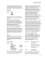
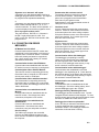
PC208 INTRODUCTION
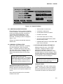
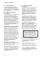
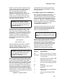
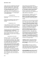
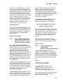
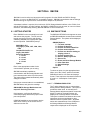
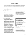
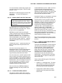
FIGURE I-1. Menu Selection
•
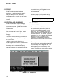
I.5 INTRODUCTION TO USER
INTERFACE
The PC208E and EDLOG programs use a
standard mouse based user interface. This
user interface is common in modern operating
systems and programs. Those familiar with this
user interface will have no difficulty with these
programs. Those who have not used this
interface should read the following sections.
Many operations are based on a mouse
however all important operations can be
accomplished without a mouse using the
keyboard.
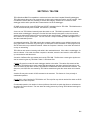
MENU NOTATION
The notation FILE | NEW | STATION indicates
the following actions: Selecting FILE on the
main menu then NEW from the subsequent
submenu, and STATION from the third
submenu (Figure I-1).
BASIC KEYS
The following keys are used to move the focus
(highlight) from control to control:
•
•
•
4
TAB is used to move to the next
control
SHIFT-TAB is used to move to the
previous control.
RETURN or SPACE is to select
(activate) the control with the focus.
The cursor keys are used to
manipulate some controls.
See the following sections for more detail.
USING THE MENU
The main menu is located at the top of the
screen. To use the mouse, click on the main
menu item and then click on the desired option
on the displayed sub menu. To use the
keyboard, press and hold the ALT key then
press the highlighted character for the main
menu item. For example, press ALT+F for the
FILE menu. Next type the highlighted
character for the desired option on the
displayed sub menu. Once a sub menu is
displayed, the cursor keys can be used to move
the cursor up, down, left, or right. Press return
to select a the option the cursor is on.
Note: When a menu option is not
available, it will be grayed-out. Grayed-out
options appear lighter. These options do
not respond when selected. Options are
usually grayed-out because:
•
The option was not installed or is not
available.
•
The option does not apply to the
current mode or operation.
Press ESC to leave a menu.
PC208 INTRODUCTION
WINDOW BASICS
Zoom Box
Title Bar
Close Box
Scroll Bar
Scroll Bar
Resize Corner
Close Box
Zoom Box
Used to close the current window usually with
out saving changes (if applicable). To use a
mouse, click on the box. To use keyboard,
press ESC, or select CANCEL button if
available. Select FILE | CLOSE to close the
main file in EDLOG.
Used to change the size of the displayed
window. Toggles between full size and current
size. To use mouse, click on box. To use
keyboard, press F5 key in PC208E. With
EDLOG use WINDOW main menu options to
alter size.
Scroll Bars
Resize Corner
Used to scroll displayed information. To use
mouse, click on arrow (triangle) at either end to
scroll in that direction. Click on the bar between
the arrows to move in larger steps. To scroll
with the keyboard, cursor keys, PAGE UP, and
PAGE DOWN key are normally used.
Used to size the window. To use with mouse,
click and drag corner to desired size. See
Zoom Box for keyboard controls.
5
PC208 INTRODUCTION
CONTROLS
Drop down list
(Combo)
Button
Text Box
Radio Buttons
Buttons
Drop Down List (Combo)
Buttons are identified by a shadow . To select a
button, click on it with the mouse. To use the
keyboard, move the focus (highlight) to the
button and press the SPACE or RETURN key.
Drop Down List allow the selection of a single
option from a displayed list. To use the mouse,
click on the small triangle character to the right
of the default option. Select the option from the
displayed list by double-clicking on it. To use
the keyboard, move the focus to the Drop Down
List and press the DOWN cursor key to display
the list. Use the UP and DOWN cursor keys to
move the highlight to the desired option then
press the RETURN key.
Text Box
Text boxes allow text to be typed in directly
when they have the focus. To use a mouse,
click on the text box then type the text. To use
the keyboard, move the focus (highlight) to the
text box and then type the text.
6
PC208 INTRODUCTION
Radio Buttons
Radio buttons allow only one of the displayed
set of options to be enabled. To use the
mouse, click on the desired option. To use the
keyboard, move the focus to the Radio Buttons
Set then use the UP and DOWN cursor keys to
select the desired option.
Check Box
Check Box
Check boxes allow one or more options to be
individually enabled. A ‘X’ indicates the option
is enabled. Click on an option to toggle it. With
the keyboard, press TAB or SHIFT+TAB to
move the focus to the desired option and press
SPACE to toggle it.
7
PC208 INTRODUCTION
HELP
Selected
link
Links
Help is invoked by pressing the F1 key,
selecting a HELP button, or using the main
menu. Help supports links to other help
sections. Links are displayed in a different color
text. Double click on a link with the mouse to
jump to the referenced section. With the
keyboard, use the TAB or SHIFT+TAB to move
the highlight to the desired option and press
RETURN. Press ALT+F1 to return to the
previous screen.
Use the scroll bars or cursor keys to scroll the
help text.
8
PC208 INTRODUCTION
STANDARD FILE SELECTION BOX
The filename can be typed in here
directly. The * character can be used to
update the list of displayed files, e.g.,
enter ‘*.PRN’ to list all files with PRN
extension. Select OK button to use any
changes.
Click on a
filename then
select OK
button or
double-click
on filename
to use it.
Select to use
current
filename or
update list of
displayed file
names.
Cancel
operation and
close window.
Directory names are followed by the ‘\’
character. Select directory name then
the OK button or double-click on
directory name to change to that
directory. ‘..\’ represents the parent
directory or directory above the current
directory.
9
PC208 INTRODUCTION
This is a blank page.
10
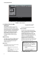
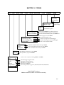
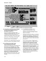
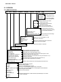
SECTION 1. PC208E
File Edit RealTime Tools DataCollection View Display Help
Index
HelpOnHelp
Getting Started
About
Screen Colors
GraphOpts Toggle
ErrorLog
Data
Scheduled
Call Now <MultiStn>
Call Now <CurrentStn>
Clock Set/Check
Send DataLogger Prog
Receive Datalogger Prog
Terminal Mode
Call
Monitor
HangUpLink
Station
Schedule
New
Open
Edlog
Reports
VS1
Short Cut
Storage Module
DosShell
Exit
Screen and
graph settings
View data & log files
Start open schedule (begin data collection)
Collect data from one or more stations now
Collect uncollected data from open station now
Following apply to open station:
Maintain datalogger clock
Transfer a program to the datalogger
Transfer the program from the datalogger
Enter remote keyboard mode
Establish communications with open station
View current measured values at open station
Close communications with open station
Edit dialing parameters for open station
Edit parameters for open schedule
Create a new or open an existing station or schedule
Start datalogger program editor
Start Split (report generator)
Edit/add voice synthesizer text
Start Program Builder
Start Storage Module programs (SMCOM,CSMCOM, SMCREAD)
Main PC208E functions
Bold text indicates if station or schedule functionality
1-1
SECTION 1. PC208E
1.1 PC208E
PC208E provides computer/datalogger
communication for data collection and real-time
data display. In addition, it provides tools for
setting the datalogger clock, transferring
datalogger programs, and testing
communication links. PC208E can also act as
a starting place to access the other software
programs.
a specified interval, the PC waiting between
calls. While waiting, datalogger initiated calls
can be answered.
In addition to a station file for each station, a
schedule (script file) is required for this type
collection.
Note: Current users of TELCOM and
GRAPHTERM (GT) should see Section 1.8.
1.2 STATIONS AND SCHEDULES
PC208E provides data computer/datalogger
communication to collect data and to monitor
current measurements. PC208E also provides
“tools” for assisting in using and maintaining
CSI dataloggers:
These operations are “attended” i.e. done at the
user’s command with a station open. Multiple
operations can be done in a single call to the
datalogger.
A station file contains the calling information for
each datalogger and is required to accomplish
the above functions.
In addition to these on-line functions, the
PC208E program can be used to schedule data
collection from one or more datalogger sites.
The stations can be scheduled for manual
collection (collection at the users' request) or for
unattended collection with each station called at
1.3 STATIONS
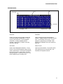
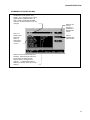
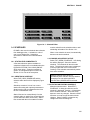
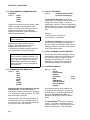
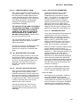
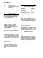
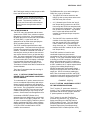
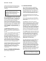
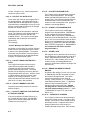
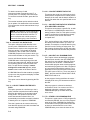
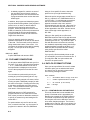
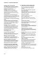
1.3.1 MAIN SCREEN
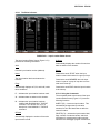
Figure 1.3-1 shows the PC208E main screen
with a station active and on-line. Notice the
station name is displayed in the top right hand
part of the screen while the station is active
(21X.STN). The “$” character in the top left
corner is visible when the datalogger has been
called and is on-line. For example, if a phone
connection is in use, the phone is off-hook and
the phone line busy. Regardless of the
connection, the datalogger will attempt to
terminate the connection if 40 seconds elapses
with no activity.
The activity box at the bottom indicates dialing
and communication activity with the datalogger.
This is primarily used as diagnostic aid. The
main screen area is used to display dialog
boxes regarding the current activity. In this
example, the datalogger clock is being checked.
FIGURE 1.3-1. Main Screen
1-2
SECTION 1. PC208E
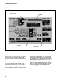
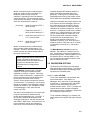
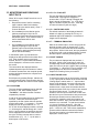
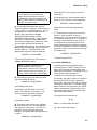
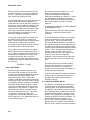
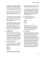
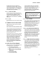
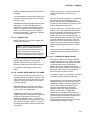
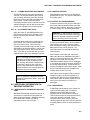
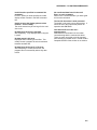
Figure 1.3-2. Station File Editor
1.3.2 CREATING A NEW STATION FILE
Each datalogger must have a station file before
it can be accessed. The station file contains the
modem and dialing information necessary to
communicate with the datalogger. A new
station is created by selecting FILE | NEW |
STATION. The dialog box above is displayed
(Figure 1.3-2).
Saving a new station automatically makes the
station active.
•
Another station is made active
•
A schedule is made active
•
A multi station collection is started
•
PC208E is terminated
•
40 seconds elapse with no activity
•
One of the other PC208 functions (under
the FILE menu) is used
•
HANGUPLINK (submenu under REALTIME
main menu) is selected.
1.3.3 MAKING A STATION ACTIVE
Select FILE | OPEN | STATION. A file dialog
box will be displayed. Select the desired
station. The station will then be made active.
The active station name is displayed in the top
right corner of the screen. Creating new
stations automatically makes the new station
active.
Making a station active does not
automatically call the station. The station is
called and brought on-line when PC208E is
told to call the station or some function is
selected that requires the station to be online.
1.3.4 EDITING AN EXISTING STATION FILE
Make the station file active. Select EDIT |
STATION. A dialog box with the current
parameters is displayed. Section 1.3.2
describes how to create a station file. Select
the SAVE buttons to save any changes. Select
the SAVE AS button to create a new station file
with the changes. Select CANCEL to abandon
any changes and close the dialog box.
Adding schedule options to a station file can
only be done while a schedule is active and
is done from the schedule editor.
Calling the station
While the active station is on-line, a “$” is
displayed in the top left corner of the screen.
Editing a station file requires that the station file
be active but does not require the station to be
on-line.
The REALTIME | CALL option calls the active
station. This selection is optional as PC208E
will call the station when any option requiring it
is selected if the station is not already online.
Once called and brought on-line, the station
remains on-line until:
1-3
SECTION 1. PC208E
1.3.5 MONITOR MODE(S)
A station must be active before data can be
collected for display. The station will be called
and brought on-line if it is not already.
Select REALTIME | MONITOR and the
numerical monitor screen will be displayed.
While in the numerical monitor, the
graphical monitor, or the location editor
screens, the mouse is not active.
See Section 3.3 (GRAPHTERM) of the PC208
manual for monitor mode descriptions.
Terminating a call
The REALTIME | HANGUP option terminate the
link to the current station.
1.3.6 SETTING/CHECKING THE DATALOGGER
CLOCK
A station must be active before its clock can be
set. The station will be called and brought online if it is not already.
Select TOOLS | CLOCK SET Select CHK to
compare the datalogger clock to the PC clock.
Select SET to set the datalogger clock and date
according to the PC clock. Select CANCEL to
close the dialog box.
Setting the datalogger clock should be done
with caution as the data storage is driven by
the datalogger clock.
1.3.7 SENDING AND RECEIVING DATALOGGER
PROGRAM (DLD) FILES
Note: EDLOG is a datalogger program
editor used to create datalogger program
(DLD) files.
A station must be active before programs can
be transferred. The station will be called and
brought on-line if it is not already.
Select TOOLS | SEND DATALOGGER PROG
to send a program to the datalogger. Select the
datalogger program to send with the displayed
file dialog box.
1-4
Caution: Sending a program to the
datalogger stops its current program and
may erase all the data in the datalogger!
ALWAYS collect any needed data from the
datalogger before sending a program!
Select TOOLS | RECEIVE DATALOGGER
PROG to retrieve and save the program from
the datalogger. Enter the file name for the
datalogger program with the displayed file
dialog box.
Normally the program is only retrieved if the
original EDLOG program is not available (e.g.
the program was entered with the datalogger
keyboard display).
Do not overwrite the DLD file created by
EDLOG as it may contain label information
not found in the DLD file received from the
datalogger.
Retrieving programs over a radio (RF) link
or over marginal links is not recommended.
1.3.8 DATA COLLECTION (SINGLE STATION)
A station must be active before data can be
collected. The station will be called and brought
on-line if it is not already.
Select DATA COLLECTION | CALL NOW
(CURRENT STN). All uncollected data (up to
all the data in the station) will be collected from
the active station. The file will be appended to a
file with the station name and a ‘DAT’ extension.
The data will be stored in the format specified in
the station file. Two formats are supported; an
ASCII comma separated format or a binary
format.
Additional data formats and collection options
are available by collecting data with a schedule
rather than on-line. See Section 3.1 for other
options.
Some station file options used with
scheduled collection are not completely
compatible with options used for on-line
collection. See Section 3.1
SECTION 1. PC208E
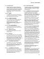
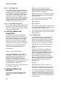
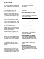
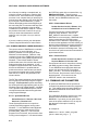
Figure 1.4-1. Schedule Editor
1.4 SCHEDULES
PC208E is also used to schedule data collection
from datalogger sites. A schedule is a list of
one or more station files. Scheduling
information is added to the individual station
files.
1.4.1 STATION FILE COMPATIBILITY
A few data collection options available for
scheduled collection are not available when the
DATACOLLECTION | CALL NOW (SINGLE
STN) menu option. A warning message is
given if an unsupported option is used. See
Section 3.1 for a list of the exceptions.
1.4.2 CREATING A SCHEDULE
Select FILE | NEW | SCHEDULE and the
schedule editor above will be displayed (Figure
1.4-1).
must be edited from the schedule editor to add
scheduling information. See Section 1.4.1.
When a new schedule is saved, it automatically
becomes the active schedule.
1.4.3 MAKING A SCHEDULE ACTIVE
Select FILE | OPEN | SCHEDULE. A file dialog
box will be displayed. Select the desired
schedule. The schedule will then be made
active. The active schedule name is displayed
in the top right hand corner of the screen.
Creating a new schedule automatically makes
it the active schedule..
Making a schedule active does not
automatically start collection from the stations.
The stations are not called until DATA
COLLECTION | SCHEDULED is selected.
1.4.4 EDITING AN EXISTING SCHEDULE
Schedules consist of a list of one or more
stations files along with optional parameters to
allow incoming calls to answered and to force
the PC to wait between calls.
Station files can be created directly from the
schedule editor or station files created with the
on-line station file editor can be used. Station
files created with the on-line station file editor
Make the schedule active. Select EDIT |
SCHEDULE. A dialog box with the current
schedule is displayed. Section 1.4.2 describes
how to create a schedule. Select the SAVE
buttons to save any changes. Select the SAVE
AS button to create a new schedule with the
changes. Select CANCEL to abandon any
changes and close the dialog box.
1-5
SECTION 1. PC208E
FIGURE 1.4-2. Station File Editor Used with Schedule Editor
1.4.5 CREATING A STATION FILE OR ADDING
SCHEDULING INFORMATION TO AN
EXISTING STATION FILE
Figure 1.4-2 shows the station file editor
available from the schedule editor. This editor
is displayed when an existing station file is
edited from the schedule editor or when a new
station file is created from the schedule editor.
See Section 5.1 (TELCOM) in the PC208
manual for detail on these parameters.
See Section 1.4.1 if station files are to be used
with on-line collection and scheduled collection.
1.4.6 STATION FILES OTHER THAN
DATALOGGER STATION FILES
Station files normally define communication and
data collection for a datalogger site. Station
files created with the schedule editor can also
be used to schedule DOS commands so that
they occur at a given interval or station files that
allow TELCOM to drop out of the wait mode at a
given interval. The option to create these
stations is given when the NEW STATION
button is selected on the schedule editor. See
Section 5.1 (Telcom) for details on the station
file types.
1-6
1.4.7 ANSWERING INCOMING CALLS
Select the CALLBACK button to add
parameters allowing the datalogger initiated
calls to be answered.
A dialog box allowing the selection of COM port
and BAUD rate is displayed. Selecting the OK
button will add /A COMx:baud (x is the port 1-4
and baud is the selected baud rate) line to the
start of the schedule and will add the wait option
/W to the end.
The PC must be turned on, PC208 must be
running and configured for CallBack, and the
datalogger must be programmed to initiate
communications in order for the Call Back
feature to work. In addition, the PC’s modem
must be configured to answer incoming calls as
the default power-on/reset configuration.
Please refer to your modem manual for specific
commands and operating instruction. Refer to
your datalogger manual for datalogger initiated
communications instructions. See Appendix A
for more details about modem dip-switch
settings and modem commands required for
datalogger initiated calls.
SECTION 1. PC208E
FIGURE 1.5-1. Collect Now From Multiple Stations
1.4.8 WAIT OPTION
Selecting the WAIT button will cause the PC to
wait between calls to the stations in the
schedule. A /W is added to the end of the
schedule. While the PC is waiting between
calls during scheduled data collection, pressing
ESC will abort the schedule and return the PC
to the PC208E program.
Collecting data with a schedule
Select DATACOLLECTION | SCHEDULED to
start the active schedule.
1.5 COLLECTING DATA FROM ONE OR
MORE STATIONS ON DEMAND
Data collection on demand for one or more
stations can be done with the
DATACOLLECTION | CALL NOW (MULTI
STN) option. When selected the dialog box
above is displayed (Figure 1.5-1).
Up to nine stations may be added for collection.
The number to the left of the station file name
indicates the order in which the stations will be
called. Any scheduling information in the
station files is ignored and the calls are started
when the START COLLECTION button is
selected. This creates a temporary schedule.
This option is always available. If PC208E has
a station active and on-line, that link will be
terminated before collections is started.
1.6 THE VIEW AND DISPLAY MAIN
MENU OPTIONS
The VIEW option on the main menu allows the
viewing of ASCII (text) files. The two default file
extensions are ERR (error files) and DAT (data
files). Files with other extension may be viewed
by changing the extension in the file dialog box.
NOTE: Only the first 255 characters of
lines longer than 255 characters will be
displayed.
The DISPLAY option has two submenu
selections; SCREEN and GRAPH OPTS
TOGGLE. The SCREEN selections allow the
color palette selection for PC208E. The
GRAPH OPTS TOGGLE allows several options
relating the graphical monitor mode to be
toggled. See Section 3.5.1 (GRAPHTERM) of
the PC208 manual.
1.7 HELP
Context sensitive help is displayed on the
bottom right portion of the main screen. This
will give information about the highlighted menu,
button, or control. Additional information is
available by pressing the F1 key. A help index
and a getting started section are available from
the main menu.
1-7
SECTION 1. PC208E
1.8 TELCOM AND GT COMPATIBILITY
PC208E station files are compatible with
TELCOM and GT stations files. PC208E
schedule files are compatible with TELCOM
script files.
PC208E uses TELCOM to do scheduled data
collection. PC208E automatically runs
TELCOM when scheduled data collection is
started. Alternatively, TELCOM can be used to
execute a schedule directly. For example,
“TELCOM hourly” could be added the DOS
AUTOEXEC.BAT file to have TELCOM
automatically start collection with a schedule
named ‘hourly.scr’ when the computer is turned
on.
1.9 DATA COLLECTION DIFFERENCES
The DATACOLLECTION | SCHEDULE and the
DATACOLLECTION | CALL NOW (MULTISTN)
data collection support the following data
collection options NOT supported by the
DATACOLLECTION | CALL NOW
(CURRENTSTN) data collection:
•
A Printable ASCII data format
•
Collection from a Storage Module
attached to a CR10(X) datalogger
•
Ability to collect a fixed number of
data arrays (rows of data) instead
of all uncollected data
•
Ability to create a new data file with
each retrieval instead of appending
the existing data file.
•
Ability to create a station file that
schedules and performs a DOS
task instead of calling a datalogger.
When a station file using any of the above
options is used for DATACOLLECTION | CALL
NOW (CURRENTSTN) data collection, a
warning message is given.
1-8
SECTION 2. EDLOG
2.1 EDLOG INTRODUCTION
EDLOG creates, documents, and edits
datalogger programs. This version of EDLOG
has the following features:
Menu-Driven Format
EDLOG's menu-driven format is easy-to-use.
Section 2.2.1 lists and describes Edlog’s menu
(see Introduction I.5 for information on using the
menus).
Window Manipulation
Multiple EDLOG programs can be displayed
simultaneously. The size and location of each
program's window can be manipulated with the
computer's mouse or by using the Window
menu (see Sections 2.2 and 2.6). Sections of
one program can be copied and pasted into
another program (see Section 2.4.3.2).
Context-Sensitive Help
Context-sensitive help is automatically provided
at the bottom of the EDLOG screen. More
detailed help is also available by pressing the
F1 function key (see Introduction I.5 for more
information).
Labels Linked
After the user enters a new input location label,
EDLOG automatically assigns it the next
available input location number (address). By
using the Input Location Editor, all of the labels
can be entered first and the program written
later. The Input Location Editor also allows the
input locations to be edited (moved, inserted,
deleted); the input location numbers are
automatically changed wherever the labels
appear in the program. For more information
about input locations and the Input Location
Editor, see Section 2.5.
Compiler
After a program is written, it must be compiled.
The compiler checks program syntax and
attempts to discover programming errors. The
compiler also creates a .DLD file. The .DLD file
excludes all comments and incorporates the
instructions required to calculate the
expressions. The .DLD file is what actually
programs the datalogger. For more
information, see Section 2.8.2.
Trace Option
When the trace option is enabled and the
program is compiled, two files are generated.
One file displays program execution timing
information; the other lists final storage labels
(see Sections 2.8.3 and 2.8.4).
2-1
SECTION 2. EDLOG
2.2 OVERVIEW
2.2.1 MENU DESCRIPTION
File
Edit
Search
Compile
Display
Options
Window
Help
Help Index
Help on Help
About Edlog
Tile
Cascade
Next
Previous
enables/disables automatic renumbering, data entry warning,
and automatic indentions.
Enable/Disable Trace
Program Security
Final Storage Area 2 CR10, 10X
Compile Program (Alt F9)
lists version number
and copyright date.
Displays windows on an equal
portion of the screen.
Only the title bars of the inactive
windows are shown.
Makes the next window active.
Makes the previous window active.
Editor Options
Toggle Screen (25/50 lines)
Screen Colors
Renumber
Rebuild Indention
Compress View
Zoom
Allows a topic to be
selected from a list.
sets the amount of final storage
area 2 memory.
options are color, black/white, or LCD.
renumbers instructions.
displays only the first line of each instruction.
Jumps to the source program.
Checks program syntax and creates a .DLD File.
Search
Search Again (Ctrl L)
Cut (Ctrl X)
Copy (Ctrl C)
Paste (Ctrl V)
Show Clipboard
Save Clipboard to Library File
Insert Instruction (shift Ins)
Delete Instruction (shift Del)
Input Locations (F5)
Final Storage Labels
View Mode 4 Table (CR10, CR10X)
Import Library File
New
Open (F3)
Save (F2)
Save As
Save/Compile/Exit (Alt F10)
Close
Close All windows.
Print to File
Print to Printer
Document DLD File
DOS Shell
2-2
Exit (Alt X)
2-2
Moves EDLOG text (see Section 2.4.3).
Copies EDLOG text (see Section 2.4.3).
Used after Cut or Copy (see Section 2.4.3).
Displays the text that will be inserted if the Paste option is used.
Creates a library file (see Section 2.5).
Allows an instruction to be selected from a list (see Section 2.3.2.1).
Deletes an instruction.
Accesses the input location editor (see Section 2.5.3).
Allows the final storage labels to be edited.
Inserts a library file into the current program (see Section 2.5).
Create a new datalogger program
Edit an existing program
Save the current datalogger program
Save the current datalogger program under a new name.
In one step, saves and compiles the current program and exits EDLOG.
Closes only the active window.
Closes all of the windows.
Documents a file that was created with the keyboard/display or an earlier
version of EDLOG.
SECTION 2. EDLOG
2.2.2 CREATING/EDITING EDLOG PROGRAMS
2.2.2.1 Creating a New EDLOG Program
Below is a step-by-step procedure for creating a
new EDLOG Program; more detailed
information is provided in the following sections.
(1) Get into EDLOG directly by typing EDLOG
and pressing <enter> or via the shell by
typing PC208E and selecting
FILE | EDLOG.
(2) Select FILE | NEW.
(3) When prompted, select the datalogger type.
(4) Develop and edit your datalogger program
(see Sections 2.3 and 2.4).
(5) Select FILE | SAVE to save and name the
program.
(6) When prompted, select YES to compile the
program.
(7) Exit EDLOG by selecting FILE | EXIT.
NOTES: CSI recommends saving your
datalogger program often.
FILE | SAVE/COMPILE/EXIT can be used
instead of steps 5, 6, and 7.
2.2.2.2 Editing an Existing Program
Except for steps 2 and 3, use the procedure
outlined in Section 2.2.2.1. For step 2, load an
existing program by selecting FILE | OPEN.
Skip step 3.
2.2.2.3 Documenting a DLD File
FILE | DOCUMENT DLD FILE is for updating a
program written in an earlier version of EDLOG
or for adding comments to a program that was
entered in the datalogger's keyboard/display.
To document a .DLD file, use the procedure
outlined in Section 2.2.2.1 except for steps 2
and 3. For step 2, select FILE | DOCUMENT
DLD FILE. Skip step 3.
2.3 PROGRAM DEVELOPMENT
EDLOG programs consist of comments,
instructions, and expressions. The body of the
program is divided into Program Tables 1 and 2
and the Subroutine Table. Each instruction and
expression must be entered in one of these
tables for the instruction or expression to be
executed. Comments can be entered anywhere
in the EDLOG program.
2.3.1 ENTERING COMMENTS
Comments are text that is ignored by the
compiler. The compiler considers any line of
text that has a semicolon as the first character a
comment.
2.3.1.1 Making an Expression or Instruction
a Comment
Press <ctrl> n while the cursor is on an
expression or instruction. This causes the
expression or the entire instruction (including all
of the parameters) to become a comment.
When an expression is continued to another
line, only the part of the expression that is on
the line where the cursor is located, is made
into a comment. To make the expression or
instruction no longer a comment, press
<shift><ctrl> n.
2.3.2 INSTRUCTIONS
2.3.2.1 Inserting Instructions
The following procedure outlines the process of
using the instruction list to insert an instruction:
(1) To bring up the instruction list, either press
<shift> <Insert> or select EDIT | INSERT
INSTRUCTION.
(2) Select a specific instruction from this list by
using the down arrow key to move the
cursor to the desired instruction.
(3) Press <enter>.
The instruction's template appears where the
cursor was originally located. This template
states the instruction name and the required
parameters. An alternate method of entering an
instruction is by typing-in the number that
identifies the instruction and pressing <enter>.
2-3
SECTION 2. EDLOG
2.3.2.2 Entering Parameters
When an instruction's template appears, the
cursor is automatically located where the first
parameter is entered. Type-in the first
parameter's value then press <enter> and the
cursor automatically moves to the next
parameter. Repeat the process until all of the
parameters have been entered.
•
The operator(s) and/or function(s) used in
the expression must be on the operator or
function list (see Section 2.3.3.2).
•
Numbers and labels that are immediately
after a function must be enclosed in
parentheses.
•
Several operators and/or functions can be
used in one expression. Operations and
functions that are enclosed in parentheses
are calculated first; the inner most
parentheses are evaluated first.
•
To continue an expression to the next line,
end the first line with an '_'.
Note: Because the instructions and their
parameters are datalogger specific, individual
instructions are listed and described in the
datalogger manuals and the help windows.
2.3.2.3 Data Entry Warning
When the Data Entry Warning is active, a
warning is displayed immediately after an invalid
input has been entered for an instruction's
parameter. The warning lists the valid inputs. A
valid input must be entered before advancing to
the next parameter.
By default, the Data Entry Warning is enabled.
To disable the Data Entry Warning, select
OPTION | EDITOR OPTIONS. Use the <tab>
key to place the cursor on the brackets and
press the <space> bar or select the brackets
with the computer's mouse. A space instead of
an 'X' between the brackets indicates this option
is disabled.
2.3.3 EXPRESSIONS
Expressions are a shortcut for processing
numbers and input data. When a datalogger
program that contains an expression is
compiled, the appropriate instructions are
automatically incorporated into the .DLD file.
2.3.3.1 Rules for Creating Expressions
•
•
•
2-4
Expressions must be set equal to the label
of the input location that will store the result.
The label must be to the left of the
expression. See Section 2.5 for more
information about input location labels.
Expressions can have both fixed numbers
and input location labels. Input locations
can ONLY be referenced by their label;
each number is always assumed to be a
constant.
Floating point numbers are limited to five
digits plus the decimal point and sign.
2.3.3.2 Operator and Function Lists
Operator List
*
(multiply)
/
(divide)
+
(add)
-
(subtract)
^
(raise to the power of; enclose negative
values in parentheses)
@ (modulo divide)
e (for CR10(X) only, scientific notation; 6e1=0.6)
Function List
COS
(cosine; angle in degrees)
SIN
(sine; angle in degrees)
TAN
(tangent; angle in degrees)
COTAN
(cotangent; angle in degrees)
ARCTAN
(arctangent; angle in degrees)
ARCSIN
(arcsine; angle in degrees)
ARCCOS
(arccosine; angle in degrees)
ARCCOT
(arccotangent; angle in degrees)
SQRT
(square root)
SECTION 2. EDLOG
LN
(natural logarithm)
2:
2
EXP
(exponent of e; EXP(2) = e )
RCP
(reciprocal; RCP(4) = 1/4 = 0.25)
ABS
(absolute value)
FRAC
(takes the fraction portion;
FRAC(2.78)=.78)
INT
P36
3
5
5
(Z=X*Y)
1:
2:
3:
P30
32
0
3
(Z=F)
1:
2:
3:
P33
3
5
6
(Z=X+Y)
1:
2:
3:
4:
5:
2.3.3.3 Examples
Below are examples of valid expressions:
=
=
=
=
=
=
P30
1.8
0
3
(Z=F)
1:
2:
3:
3:
(takes the integer portion;
INT(2.78)=2)
Zee
es
Root
avg
length
TempF
P31
2
5
(Z=X)
1:
2:
Vee+Ex
tee^(-2)
SQRT(ABS(data))
(data1+data2+data3+data4+data5)/5
SQRT((adj^2)+(opp^2))
(TempC*1.8)+32
The following section of a CR10(X) datalogger
program uses an expression to convert
Temperature from Celsius to Fahrenheit:
Execution Interval = 10 sec
6:
2.4 EDITING EDLOG PROGRAMS
2.4.1 EDITOR KEYSTROKES
The following keystrokes can be used to edit an
EDLOG program:
<ctrl> Home
View Top of File
<ctrl> End
View Bottom of File
<ctrl> PgUp
View Top of File
<ctrl> PgDn
View Bottom of File
TempF = (TempC*1.8)+32
<ctrl> n
Change to a Comment Line
When this program is compiled, the .DLD file
contains the following instructions. The last 5
instructions calculate the expression.
<shift> <ctrl> n
Un-Comment a Line
PgUp
Page Up
1:
PgDn
Page Down
Enter
Move to Next Field or Create
New Line
Tab
Move to Next Field or Line
<shift> Tab
Move to Previous Field or Line
<shift> Ins
Select an Instruction from a
Dialog Box
1:
01:
02:
03:
04:
05:
06:
1:
2:
3:
4:
5:
6:
Temperature (107) (P11)
1
REPS
2
Channel
1
Excitation Channel
2
Loc [TempC]
1
Mult
0
Offset
P11
1
2
1
2
1.0
0.0
(Temperature, 107)
2-5
SECTION 2. EDLOG
<shift> Del
Delete the Instruction or Line
Under the Cursor
(2) Select EDIT | CUT to move the text or
select EDIT | COPY to copy the text.
Up Arrow
Move Up One Line
(3) Move the cursor to the location where the
moved or copied text will reside.
Down Arrow
Move Down One Line
Right Arrow
Move One Column Right
Left Arrow
Move One Column Left
<ctrl> Left Arrow Move from input location label
to input location number.
<Esc>
Close File or Dialog Box
<alt> Z
Select Main Menu Option (Z
is a key letter)
<alt> X
Close All Files and Exit Edlog
2.4.2 EDITING COMMENTS, INSTRUCTIONS,
AND EXPRESSIONS
To edit Comments, Expressions, and the
Instruction's parameters, move the cursor to the
appropriate text and retype it. To delete an
entire instruction, move the cursor to the
desired instruction and select EDIT | DELETE
INSTRUCTION. See the Cut, Copy, Paste, and
Clipboard section for moving or copying
sections of the program.
2.4.3 CUT, COPY, PASTE, AND CLIPBOARD
OPTIONS
2.4.3.1 Moving or Copying Text within the
Same Program
EDIT | CUT, EDIT | COPY, EDIT | PASTE, and
EDIT | CLIPBOARD allow sections of the
program to be moved or copied to another area
of the program. The following steps are
required for moving or copying sections of the
program:
(1) Either use the computer's mouse or the
<shift> and arrow keys to select all of the
text that will be moved or copied.
NOTES: You cannot move or copy
protected text (Tables, Execution Intervals).
To move or copy an Instruction, the entire
instruction, including all of the parameters,
must be selected.
2-6
(4) Select EDIT | PASTE. The text is now
moved or copied to the designated location.
Steps 3 and 4 can be repeated allowing text to
be copied to many areas of the program.
EDIT | CLIPBOARD displays the text that is
inserted if steps 3 and 4 are repeated.
2.4.3.2 Moving and Copying Sections from
One Program to Another
The step-by-step procedure listed below uses
EDIT | CUT, EDIT | COPY, EDIT | PASTE, and
EDIT | CLIPBOARD:
(1) Load both datalogger programs onto the
computer.
(2) Either use the computer's mouse or the
<shift> and arrow keys to select all of the
text that will be moved or copied.
NOTES: You cannot move or copy
protected text (Tables, Execution Intervals).
To move or copy an Instruction, the entire
instruction, including all of the parameters,
must be selected.
(3) Select EDIT | CUT to move the text or
select EDIT | COPY to copy the text.
(4) Move the cursor to the location on the other
program where the moved or copied text
will reside.
(5) Select EDIT | PASTE. The text is now
moved or copied to the other datalogger
program.
By moving the cursor to other sections of the
program and repeating step 5, text can be
copied to many areas of the program.
EDIT | CLIPBOARD displays the text that is
inserted.
2.4.4 USING LIBRARY FILES
Library files can be inserted into any EDLOG
program.
SECTION 2. EDLOG
2.4.4.1 Creating a Library File
The following steps describe creating a library
file:
(1) Either use the computer's mouse or the
<shift> and arrow keys to select all of the
text that will be saved in the library file.
NOTES: Protected text (Tables, Execution
Intervals) cannot be copied into a library file.
Entire instructions, including all of the
parameters, must be selected.
(2) Select EDIT | CUT or EDIT | COPY.
(3) Select EDIT | SAVE CLIPBOARD TO
LIBRARY FILE.
(4) When a window appears, type-in the Library
file name.
(5) Select OK with the computer's mouse or
press tab until the cursor is on OK and
press enter.
2.4.4.2 Inserting a Library File into a
Program
The following steps describe inserting a library
file into an EDLOG program:
(1) Move cursor to the location where the text
will reside.
(2) Select EDIT | IMPORT LIBRARY FILE.
(3) When a window appears, select the desired
library file's name. The file name is
selected by typing it in, by using the
computer's mouse, or by using the tab key
to get to the Files section and then using
the arrow keys to move the cursor to the
desired file.
(4) Select OK with the computer's mouse or
press tab until the cursor is on OK and
press enter.
(5) The library file is now copied into the
EDLOG program.
2.4.5 RENUMBERING THE INSTRUCTIONS
whenever instructions are inserted or deleted.
By default automatic renumbering is enabled.
To improve performance on slow computers,
the Automatic Renumbering can be disabled by
selecting OPTION | EDITOR OPTIONS. Use
the <tab> key to place the cursor on the
brackets and press the <space> bar or select
the brackets with the computer's mouse. A
blank instead of an 'X' between the brackets
indicates this option is disabled. When
Automatic Renumbering is disabled, the user
can periodically renumber the instructions by
selecting DISPLAY | RENUMBER. This option
renumbers the table where the cursor is
located.
2.4.6 COMPRESS VIEW OPTION
When DISPLAY | COMPRESS VIEW is
selected, the first line of each instruction is
displayed. This enables the program structure
to be easily seen.
This option can also be used to advance to a
specific instruction. To advance to a specific
instruction, move the cursor to an instruction in
the compressed view’s window. By pressing
<enter>, the main window advances to the
selected instruction.
Instructions cannot be edited in the compress
view’s window. The F7 function key is used to
toggle between the compress view’s window
and the main window.
2.5 INPUT LOCATIONS
Each input location has an input location
number and a label that appears whenever the
input location is referenced in the program.
EDLOG automatically assigns input location
numbers as labels are entered.
2.5.1 ENTERING INPUT LOCATIONS
When a parameter designates an input location,
the cursor automatically is located between the
brackets, which is where the label is keyed-in.
When a new label is entered, the next available
input location number is automatically assigned
to that label. A list of existing labels can be
accessed by pressing the <F6> function key.
From this list, the user can select an existing
label.
When Automatic Renumbering is enabled, the
instructions are automatically renumbered
2-7
SECTION 2. EDLOG
Labels can have up to nine characters. The
first character must be a letter. The allowed
characters are numbers, letters, #, and _. The
following labels are reserved for expressions
and should not be entered by the user: CSI_R,
CSI_2, CSI_3, . . . CSI_95.
To enter the input location number instead of
the label, press <ctrl> left arrow. This will move
the cursor to where the location number is
entered; the computer's mouse can also be
used to move the cursor.
For Example:
When the following is a section of an EDLOG
program, the TempC and BatteryV input
locations are sampled.
10: Temperature (107) (P11)
01:
1
REPS
02:
2
Channel
03:
1
Excitation Channel
04:
1
Loc [TempC]
05:
1
Mult
06:
0
Offset
2.5.2 REPS
Many input/output and output processing
instructions have a repetition parameter.
Repetitions (REPS) allow one programming
instruction to measure several identical sensors
or to process data from several input locations.
When REPS are greater than 1, the input
locations are assigned consecutive numbers
(e.g., with REPS of 2 and LOC of 5, the input
locations are 5 and 6). Each rep label is the
initial label with a '#' and the next consecutive
number.
For Example: With 3 REPS and a label of
'data', the labels for each REP are: data#1,
data#2, and data#3.
Only the first location of an output processing
instruction is linked to the label. Reps of
input/output instructions and output processing
instructions are not linked.
2-8
11: Battery, Volt (P10)
01:
2
Loc [BatteryV]
12: If time is (P92)
01:
0
minutes into interval
02:
60
minute interval
03:
10
Set high Flag 0 (output)
13: Sample (P70)
01:
2
Reps
02:
1
Loc [TempC]
NOTE: If an input location is inserted
between the TempC and BatteryV location,
the inserted location will be sampled instead
of BatteryV.
2.5.3 INPUT LOCATION EDITOR
Input location labels and numbers can be
entered and edited by using the Input Location
Editor Screen. To access the Input Location
Editor Screen, select EDIT | INPUT LABELS.
SECTION 2. EDLOG
2.5.3.1 The Editor's Screen
FIGURE 2.5-1. Input Location Editor Screen
The Input Location Editor Screen (Figure 2.5-1)
provides the following information:
# Writes
Addr
Automatically displays the number of times that
data are written to this location.
Lists the input location number (address).
Blocks
Name
Contains the word 'START' when the input
location is the initial location for a group of reps.
The input location labels are between the
brackets.
Flags
Contains the word 'MEMBER' when the input
location is part of a group of reps but is not the
initial nor the last rep.
Automatically displays an R, W, and/or M, under
these conditions:
Contains the word 'END' when the input location
is the last rep.
R -- indicates the input location has been read.
2.5.3.2 Using the Commands
W -- indicates data are written to this location.
M -- indicates the input location has been
modified with the MANUALLY TOGGLE
command. See Section 2.5.3.2 for a
description of the MANUALLY TOGGLE
command.
# Reads
Automatically displays the number of times the
input location is read.
The commands listed at the bottom of the Input
Location Editor Screen (Figure 2.5-1) have the
following functions:
INSERT (F2) -- inserts an input location. This
automatically changes the input location
numbers for all of the labels that are after the
inserted location.
DELETE (F3) -- deletes the input location label,
flags, number of reads and writes, and block
information for a designated location number.
Whenever the datalogger program references a
2-9
SECTION 2. EDLOG
deleted location label, the input location's
number automatically becomes 0.
MOVE (F4) -- moves the input location to a
different number. This might change several
input location numbers.
TOGGLE MANUAL (F5) -- allows specific input
locations to not be affected by the optimize
command. This is used for burst mode,
indexed loops, or other situations where it's not
clear to EDLOG that the locations are being
written to.
OPTIMIZE (F6) -- deletes input locations that
aren't referenced or written to and aren't
marked manual. This might change several
input location numbers.
BLOCK (F7) -- sets the manual flag for a range
of locations. The block command also allows a
range of locations to be labeled simultaneously.
This command does not change existing labels.
2.5.3.3 Rep Warning Screen
The warning screen appears when attempting
to:
(1) Insert a location within a rep block.
(2) Delete only a few members of a rep block.
(3) Move only a few members of a rep block.
2.7 INDENTION
Indention is typically used with If Then/Else
sequences and loops. Both manual and
automatic indentions are available.
2.7.1 MANUAL INDENTION
To use the manual indention, follow the
procedure outlined below:
(1) Select OPTION | EDITOR OPTIONS.
(2) In the small shaded box, type-in the amount
of spaces that the instructions are to be
indented and press <enter>.
(3) Move the cursor to the instruction that you
want indented and press either <ctrl> right
arrow or <ctrl> left arrow; the instruction is
indented the direction the arrow is pointing.
2.7.2 AUTOMATIC INDENTION
Automatic indention indents all If Then/Else
sequences and Loops. To use the automatic
indention, follow the procedure outlined below:
(1) Select OPTION | EDITOR OPTIONS.
(2) Enable the Automatic Indention option by
using the <tab> key to place the cursor on
the brackets and pressing the <space> bar
or by selecting the brackets with the
computer's mouse. An 'X' between the
brackets indicates this option is enabled.
2.6. WINDOWS
Multiple windows can be displayed on the
computer screen. The size and location of each
window can be manipulated with the computer's
mouse or by using the Window Menu (see
Section 2.2.1).
NOTE: The Window Menu cannot be used
with help windows.
The active window can be closed by using the
computer's mouse or pressing the Esc key.
Also available for closing windows are the
FILE | CLOSE and FILE | CLOSE ALL options
(see Section 2.2.1).
2-10
(3) In the small shaded box, type-in the amount
of spaces that the If Then/Else sequences
and Loops are to be indented and press
<enter>.
2.7.3 REBUILD INDENTION
DISPLAY | REBUILD INDENTION undoes all
manual indentions and rebuilds automatic
indentions. Automatic indentions may need to
be rebuilt when editing instructions cause the
indentions to get misaligned.
SECTION 2. EDLOG
2.8 FILE TYPES
2.8.1 FILES WITH A *.CSI EXTENSION
These are the EDLOG program files that the
user edits. When an EDLOG program is saved,
EDLOG automatically adds a .CSI extension to
the program's name. Existing .CSI files can be
loaded onto EDLOG by selecting FILE | OPEN.
Although .CSI files are ASCII files, editing the
files with a text editor can affect the EDLOG
files so that they no longer compile.
2.8.2 FILES WITH A *.DLD EXTENSION
These files are ready for the datalogger. They
are produced by compiling an EDLOG program
or by entering the datalogger program via the
keyboard/display. Whenever an EDLOG
program is compiled, any existing .DLD files
with the same name are overwritten. .DLD files
that were created with an older version of
EDLOG or created with the keyboard/display
can be documented by selecting
FILE | DOCUMENT DLD.
2.8.3 FILES WITH A *.PTI EXTENSION
These files are produced by the EDLOG
compiler when the Enable Trace option is
enabled. This option is accessed through
OPTION | ENABLE/DISABLE TRACE.
Whenever an EDLOG program is compiled, any
existing .PTI files with the same name are
overwritten.
2.8.4 FILES WITH A *.FSL EXTENSION
These files are produced by the EDLOG
compiler when the Enable Trace is enabled.
This option is accessed through
OPTION | ENABLE/DISABLE TRACE.
Whenever an EDLOG program is compiled, any
existing .FSL files with the same name are
overwritten.
.FSL files list the final storage labels. These
files can be viewed by using the PC208E View
menu (Section 1.6). They can also be loaded
into a text editor.
2.8.5 FILES WITH A *.PDF EXTENSION
These files are EDLOG programs that can be
printed or used with a text editor. .PDF files are
produced by selecting FILE | PRINT TO FILE.
2.8.6 FILES WITH A *.LBR EXTENSION
These are library files. Library files allow a
section of a program to be inserted into any
EDLOG program. To avoid programming
errors, the library file and the EDLOG file should
be for the same type of datalogger. For more
information on library files, see Section 2.4.4.
.PTI files show the execution times for each
instruction, block (e.g., subroutine), and table as
well as the number of final storage locations
used per day. The execution times are
estimates. PTI files do not account for If
commands, Else commands, or repetitions of
loops. For some instructions, the execution
times are listed as 0. This occurs when the
execution time is difficult to calculate (e.g.,
Burst Mode).
.PTI files can be viewed by using the PC208E
View menu (Section 1.6). They can also be
loaded into a text editor.
2-11
SECTION 2. EDLOG
This is a blank page.
2-12
SECTION 3. GRAPHTERM
GraphTerm is a terminal emulator program with real time graphical monitoring capability that can automatically collect Final Storage data from Campbell Scientific 's CR10(X), 21X(L), and CR7 dataloggers.
Most GraphTerm features are present in PC208E. The standalone GraphTerm retains compatibility with
previous versions for command line capability. GraphTerm is run by typing "GT" on the DOS command line.
3.1 THE STATION FILE
After you enter "GT" on the DOS command
line, GraphTerm asks you to:
Enter Station Name (add /E to
alter Parameters):
When a new station name (e.g., "LOGGER")
is entered or the /E option is exercised,
GraphTerm will prompt:
Telecommunications Parameters For Station:
Datalogger Type:
Use Asynchronous Communications Adapter:
Communications Baud rate:
Data File Format:
Final Storage Collection Area:
LOGGER
CR10X
Security Code: 0
COM1
9600
Comma separated ASCII
Area 1
Interface Device:
The station file defines the datalogger and the
communication path to be used. Once the
necessary parameters have been entered, a file
is saved with the station name plus the .STN
extension. The parameters will not have to be
entered the next time the station is used. The
station parameters of an existing station can be
edited by appending /E to the station name (i.e.,
"LOGGER/E" for the station with the name
"LOGGER").
When station file screen (above) appears,
"CR10X" after datalogger type will be
highlighted. Press the space bar to scroll
through the datalogger type options. Press
return to select the desired option and advance
to the next parameter. Once again you may
scroll the options by pressing the space bar,
and enter the choice by pressing return. After
the interface device(s) is selected, type control
P (the control and P keys) to save the station
file and bring up the GraphTerm OPTIONS
menu. "Escape" will bring up the OPTIONS
menu without saving the station file. The station
file parameters are described below.
3.1.1 DATALOGGER TYPE
Options:
CR10X
Security Code: 0
CR500
Security Code: 0
CR10
Security Code: 0
21X
CR7
300 Series
Security Code: 0
[21X (2 PROM)]
[CR7 w/700 CM]
[CR21]
[DSP4 Display]
[None]
The options shown in brackets, [], are "hidden"
and will only be displayed if "H" is pressed to
scroll the options. "None" will result in an
options menu with general purpose file receive
and transmit options. The CR10(X) option
allows entry of a security code: GraphTerm
automatically unlocks security with the code.
The DSP4 Display type should only be selected
when downloading a program through the DSP4
(set the baud rate to 1200). When using the
monitor and graphics options of GraphTerm,
connect the PC directly to the datalogger.
The 2 PROM 21X, CR7 with 700 control module
and CR21 do not support GraphTerm's monitor
and graphics capabilities.
3-1
SECTION 3. GRAPHTERM
3.1.2 ASYNCHRONOUS COMMUNICATIONS
ADAPTER
Options:
COM1
COM2
COM3
COM4
GraphTerm will allow you to use COM1, COM2,
COM3, or COM4 in communicating with a
station. Functions of the PC201 card are not
supported other than as a PC COM port.
GraphTerm addresses COM3 and COM4 as
3E8 and 2E8 respectively.
NOTE: If COM3 or COM4 is specified,
refer to Appendix B.
Different ports can be used for different
stations. The COM port must look like a
standard IBM Serial Asynchronous
Communications Adapter which will allow the
use of interrupts for receiving characters.
NOTE: GraphTerm leaves the COM Port
and its interrupt completely disabled. The
Port must be reinitialized before it is used
(e.g., if the Port is used for a printer, the
DOS MODE command must be issued
before the PRINT command will address
the COM Port).
3.1.4 DATA FILE FORMAT
Options:
Comma Separated ASCII
As stored in datalogger
"Comma Separated ASCII" strips all IDs,
leading zeros, unnecessary decimal points and
trailing zeros, and plus signs. Values are
separated by commas. Arrays are separated by
Carriage Return Line Feed. Comma Separated
ASCII requires approximately 6 bytes per data
point.
Example:
1,234,1145,23.65,-12.26,625.9
1,234,1200,24.1,-10.98,650.3
"As Stored in Datalogger" stores data in the
file exactly as received from the datalogger.
This is in binary Final Storage Format. See the
datalogger operator's manual for a description
of the Final Storage format.
3.1.5 FINAL STORAGE COLLECTION AREA
The CR10(X) and CR500 dataloggers may be
programmed to have two Final Storage areas.
You must select Area 1 (default) or Area 2
(optional) Final Storage Area. If another
datalogger is selected, this parameter will
automatically be labeled "not applicable."
3.1.6 INTERFACE DEVICE
3.1.3 COMMUNICATIONS BAUD RATE
Options:
300
[600]
1200
[2400]
[4800]
9600
[19200]
[38400]
Valid baud rates for the dataloggers are 300,
1200 and 9600. The baud rates shown in
brackets are "hidden" and will only be displayed
if "H" is pressed to scroll the options. Use 1200
baud if the DSP4 is selected.
The baud rate for the CR7 with the Model 700
Control Module is set by a hardware jumper in
the control module. The GraphTerm baud rate
must be set to that same baud rate.
3-2
Options:
End
SC32A
Hayes Modem
Number:
RF Modem
MD9
RAD Modem
SC95 Short Haul
Generic Modem
Number:
Path
Addr:
Up to three interfaces can be between the
computer and the datalogger. After the first
interface device is entered, GraphTerm will
prompt for Interface Device "#2:", etc.
Appendix A describes the Generic Modem
option.
The Hayes ModemTM requires a telephone
number. The number can be entered as a
continuous string (e.g., 18017532342) or with
dashes or spaces (e.g., 1-801-753-2342).
SECTION 3. GRAPHTERM
Modem commands can be included with the
telephone number, but the commands and
telephone number cannot exceed 40
characters. Depending on the first character
entered GraphTerm will automatically send a
set up string to the modem. If the first character
of the user entered phone number is:
phone digit - GraphTerm sends "ATDT" +
phone number
; - GraphTerm sends "AT" +
phone number without the ";"
P or T - GraphTerm sends "ATD" + P
or T + phone number
all other - GraphTerm sends "AT" +
phone number
Modem commands can be included with the
phone number to alter default settings. For
example: "S7=60DT" preceding the telephone
number sets the time that the Hayes waits for
the carrier to 60 seconds.
NOTE: High speed and fax modems have
a larger command set and are more
complex than the old 1200 baud modems.
Appendix A.3 describes the use of
initialization files to configure these
modems.
The RF Modem requires a path. The path
consists of a string of RF Modem link IDs,
separated by commas or spaces. This string
cannot exceed 40 characters. If repeaters are
used to get between the first RF Modem and
the last, then more than one ID must be
entered. All the repeater numbers are entered
on the same line. For example, if you are going
through one repeater to the datalogger, and the
repeater ID number is "123" and the ID number
on the datalogger is "234", then enter the
number "123 234".
The letter F can be added to the end of the path
to speed communication between the RF
modem and the datalogger (e.g., 123 234F). If
the end link is between an RF Modem and
datalogger, adding the F sets the end link baud
rate to 9600. Without the F, the baud rate is set
to that used at the start of link (computer or
phone to RF) with a maximum of 1200 baud.
Campbell Scientific RF Modems default to a
higher speed RF transmission than used
previously. If older (prior to February 1989)
DC95 Modems are being used, please consult
the RF Manual for compatibility considerations.
GraphTerm calculates how long it needs to wait
for a response from the datalogger, based on
the number and type of interfaces in the link.
There are several cases in which the default
calculation will not allow enough time. Some of
these are: a telephone link that uses a satellite
repeater (e.g., calling Alaska from continental
U.S.), a cellular telephone modem link, or an
RF network that uses a translator repeater
(contact CSI prior to attempting this). The
length of time GraphTerm waits can be
extended by entering "+nnn" at the end of the
telephone number or RF path; nnn is a number
in hundredths of seconds (e.g., 100 equals 1
second).
The MD9 Multidrop Interface requires an
address. The address is a number from 0 to
255. This address must match the address in
the MD9 being called. When the MD9 is not the
first interface device, the base MD9 (i.e., the
one connected to the telephone modem) must
have its address set to 255.
3.2 GRAPHTERM OPTIONS
The GraphTerm OPTIONS menu will appear
after specifying the desired station. The options
available will depend upon the datalogger type.
All options are described below.
3.2.1 C -- CALL STATION
The C option establishes communication with
the selected station. If the station is a
datalogger, the C option will get the datalogger
to return the "*" command prompt, after which
GraphTerm will automatically go into the
terminal emulator option. If the "*" prompt is not
returned after several attempts to establish
communication with the datalogger, GraphTerm
will re-display the options menu.
To call a different datalogger in a network, first
switch station files using the Edit option (Section
3.10).
3-3
SECTION 3. GRAPHTERM
3.2.2 T -- TERMINAL EMULATOR
T is the terminal emulator option and is
available for any datalogger type. Keyboard
entries are transmitted out the selected COM
port and characters received are displayed on
the monitor Escape or Ctrl_ returns GraphTerm
to the options menu.
3.2.3 D -- DOWNLOAD PROGRAM TO
DATALOGGER
The D option will program the datalogger from a
disk file. The datalogger will be called
automatically if it is not on line when the D
option is executed. Different programming
methods are used, thus it is essential that the
correct datalogger type has been selected. The
type of file needed is the .DLD file created by
EDLOG or a file created by saving the
datalogger or DSP4 programming information.
These files all have the same format. If the file
is not found, the D option is terminated.
Entering "[path]*" will get a list of files with the
.DLD extension.
GraphTerm will program the datalogger by
sending the .DLD file. When the datalogger has
received the entire file, GraphTerm will
command it to compile the program and start
logging if no compile errors are found.
After successful programming (no datalogger
compile errors), GraphTerm will place the
datalogger in the Telecommunications mode
and enter the Terminal Emulator option so that
the user may review the datalogger operation or
send the disconnect commands as desired.
If a datalogger compile error is found,
GraphTerm will disconnect the datalogger. For
all datalogger types except the CR7 with the
Model 700 Control Module, the program is
erased from the datalogger before
disconnecting.
The CR10(X), 21X and the CR7 are
programmed using the datalogger's *D mode.
The program is sent to the datalogger in 220
byte blocks. Labels are not sent.
The monitor displays when a block is sent,
received by the datalogger, and entered into
program memory. A missed block will be resent
automatically. The file may even be started
over to assure the datalogger receives the
programming file correctly.
3-4
3.2.4 S -- SAVE PROGRAM FROM
DATALOGGER
The S option saves the datalogger's program on
a disk file. The user specifies the filename.
Enter "[path]*" for a list of existing .DLD files. If
no extension is provided, GraphTerm will add
the extension .DLD to the filename. The
datalogger will automatically be called if it is not
on line when the S option is executed. The
program is displayed on the monitor as it is
received.
If the program has no compile errors, the
datalogger will be left in a logging status and in
the telecommunications command mode and
GraphTerm will enter the Terminal Emulator
option. The user can monitor the datalogger
operation, edit the program in the datalogger, or
send the disconnect commands.
If the program has compile errors, the
datalogger is left in the REMOTE KEYBOARD
mode. The user must either correct the
program, or erase it before it is possible to issue
the commands necessary to disconnect the
telecommunications link. Otherwise, the user
will need to let the link time out. Specific
instructions based on the datalogger type will
appear on the monitor.
NOTE: If the RF Modem is one of the
interface devices, GraphTerm cannot save
the datalogger program automatically
unless certain conditions and procedures
are followed. The baud rate must be set to
300 baud and the RF link quality must be
good.
3.2.5 K -- PC TIME TO DATALOGGER CLOCK
The K option will set the datalogger clock using
the computers time. The K option is not
available for the CR21.
When 'K' is keyed TERM will show the
datalogger time, the PC time, and will prompt:
Set the datalogger time to PC time? (Y/N):
If 'Y' is keyed TERM will set the datalogger
clock and return to the Options Menu. If 'N' is
keyed then the 'K' option is aborted and TERM
returns to the Option Menu.
SECTION 3. GRAPHTERM
3.2.6 P -- CREATE POWER-UP PROM
The P option is available for the CR10 and 21X
with special software. This option creates a file
that contains all the PROM software plus the
current datalogger program. When the file is
burned into a 27C256 (for CR10) or 27C64 (for
21X) PROM and placed in the appropriate
datalogger, the datalogger will power-up
programmed and logging.
THE CODE IN THE CR10 AND 21X PROMS IS
COPYRIGHTED SOFTWARE. A SOFTWARE
LICENSE AGREEMENT WITH CAMPBELL
SCIENTIFIC, INC. MUST BE COMPLETED
BEFORE BURNING ANY PROMS WHICH
INCLUDE THIS SOFTWARE. Contact CSI for
the cost of the software license.
The user specifies the filename. If no extension
is specified, GraphTerm adds the extension
.OBJ to the filename.
After the file is received, the datalogger is left in
the telecommunications command state.
GraphTerm will enter the Terminal Emulator
option.
3.2.7 M -- MONITOR INPUT LOCATIONS
The M option digitally monitors up to 33 of the
first 254 input locations, shows input location
assignments for up to three graphs, and allows
the user to see and change the status of the
datalogger's user flags and control ports.
Monitoring and graphics are described in
Section 3.3.
3.2.8 U -- COLLECT UNCOLLECTED DATA
The U option will collect all data stored in the
datalogger since the last retrieval of data;
(GraphTerm keeps track of where it leaves off
after each data collection). Data collected with
the U option is automatically appended to the
file StationFilename.DAT. That is, the data file
consists of the same name as the current
station file with a .DAT extension.
The data are stored in the .DAT file in the
format selected in the station file: comma
separated ASCII or binary (same as in the
datalogger).
3.2.9 E -- EDIT STATION PARAMETERS
The E option allows the user to edit the
parameters of the current station, or
establish/edit the parameters for another
station. See Section 3.1 for instructions on
setting up a station file. If an MD9 or RF
network is being accessed via telephone,
GraphTerm can be told to only hang up the
MD9 or RF portion of the existing link by
appending /9 or /R to the station name when
changing to the next station, allowing several
stations to be called with a single phone call.
3.2.10 V -- VIEW GRAPHICS FILE
The V option will display any file that has been
captured with the view save command in
graphics mode. The view save command
stores a "snapshot" of the graph screen to a
data file named V_STNFIL.OOO, where
STNFIL the station file name (or the first six
characters of it). Each time a new screen is
saved, the file extension is incremented.
When the V option is selected, GraphTerm will
prompt "Graphics screen file name:". A
directory of all screen files can be displayed by
entering a "*". After entering the filename of an
existing graphics file, the image will be
displayed. At this point, the Up Arrow and
Down Arrow keys will automatically display the
next and previous graphics file respectively.
That is, the Up Arrow automatically increments
the extension of the screen file and displays it,
while the Down Arrow will decrement the file
extension and display it.
Some versions of DOS support a graphical
“print screen”, allowing graphs to be printed.
See the “graphics” command in DOS Help.
3.2.11 Q -- QUIT
Quit GraphTerm by pressing Q. GraphTerm
leaves the COM Port and its interrupt
completely disabled. Subsequent programs
must reinitialize the Port before using it (e.g., if
the Port is used for a serial printer, the MODE
command must be issued before the DOS
PRINT command will address the COM Port).
3-5
SECTION 3. GRAPHTERM
3.3 MONITORING AND GRAPHING
INPUT DATA
When "M" is keyed, GraphTerm will do one of
the following:
1. Request the name of the file containing
Input Location Labels for this station.
(Default file is the station name.) Enter "*"
to list all .DLD files.
2. Go immediately into the Monitor option
(without prompting for file) if the "D"
(Download) option was selected previous to
the Monitor option. The Location Labels of
the file downloaded will be used
automatically.
3. Go immediately into the Monitor option
(without prompting for file) if the "M"
(Monitor) option was selected previously.
The Location Labels specified previously
will be used automatically.
In the Monitor option, input locations are
displayed as last specified for the station file in
use. If the locations were not previously
defined, the first 11 Input locations and labels
will be displayed in a column on the center of
the screen.
The rate at which the displayed data are
updated depends upon the numbers of values
monitored, the baud rate, the computer speed,
and the interfaces between the computer and
the datalogger.
Exit M option by pressing Escape. Monitor will
end automatically after communication with the
datalogger is broken and a time out has elapsed.
3.3.1 LOCATIONS
The Input locations displayed can be changed
by keying 'L' and, when TERM prompts
"Locations:", the desired location numbers
separated by commas.
A total of 33 Input locations may be displayed at
one time. Continuous locations may be
specified by the first number then two periods
and the last number. For example, 1..33 would
display the first 33 Input locations, or 1..11,
22..32, 89..99 would display locations 1 through
11, 22 through 32, and 89 through 99. If more
than 11 Input locations are specified, then they
will be displayed from the left of the screen to
the right. Entering commas with no number
between them (e.g., 1..5,, 7..11) will leave a
blank space on the screen.
3-6
3.3.2 F1..F8 -- FLAG SET
The user flag status is shown below the input
location data. High flags are displayed in
reverse video. Keys F1 through F8 toggle user
flags 1 through 8 respectively. (i.e., If the flag is
high, the function key will set it Low. If the flag
is Low the function key will set it high.)
3.3.3 D -- DIGITS DISPLAYED
The default resolution of the displayed data will
default to 3 digits; by pressing the "D" key, an
additional digit will be displayed. A maximum of
6 digits can be displayed.
3.3.4 T -- TERMINAL EMULATOR
While in the monitor option, a user can get into the
terminal emulator option by pressing the "T" key.
The top portion of the screen will be windowed for
this purpose. While in this mode, the input locations
on the screen will not be updated until the Terminal
Emulator option is exited by pressing Escape.
3.3.5 PORT TOGGLE
The port status is displayed with the numbers 1
through 8. When a port is set high (5 volts), the
corresponding number will be displayed in reverse
video; the user can set port 1 high or low by pressing
"P" and then "1". When the "P" key is pressed, a "P"
will be displayed on the screen indicating that
GraphTerm is waiting for the port number.
3.3.6 INPUT VALUE LOAD
To load a fixed value into an Input location, press the
"I" key; a prompt at the bottom of the screen will read
"Change Input Location value 11:". Input location
eleven will be displayed in reverse video when the
monitor mode is entered. To enter a new value in
location eleven, simply enter the number after the
prompt and press return; the number is then entered
into Input location eleven. To load other Input
locations, enter the Input location then a colon and
the value to be put in that location, then press return.
Several Input locations can be loaded with one
command by separating each Input location and
value with a comma. Up to 100 characters can be
entered in one command. To load Input locations
12, 14 and 15 with the values 55, 1 and 100
respectively, the following key strokes would be
given: "12:55,14:1,100". Data values separated by
commas will be loaded at consecutive locations.
The last Input location to be loaded will then be
displayed in reverse video.
SECTION 3. GRAPHTERM
3.3.7 COLLECT DATA
This option allows a collection interval to be
entered. While in the monitor or Graph Mode,
GT will automatically collect data on the interval
entered. Simply pressing "Enter" in response to
the request for an interval forces immediate
data collection. Section 3.2.8 discusses the
datafile format.
3.3.8 S − SOUND
"S" toggles sound on and off. With sound on,
unique tones signal data collection, a flag going
high, a flag going low, and view save.
3.4. G − GRAPHICS MODE
The "G" option acts as a toggle to either enter
or exit the Graphics Mode. All graphs are
displayed as per the current Graph
Specifications file (See the "L" option). Once in
Graphics Mode, the following options are
available:
3.4.1 H − HELPS SHOW/REMOVE
"H" acts as a toggle that will either display or
hide the help box in the upper right hand corner
of the graphics screen.
3.4.2 G − GRAPH ENTER/EXIT
"G" acts as a toggle to either enter or exit the
Graphics Mode.
3.4.3 R − RE-SCALE
Causes all graphs that are set to auto-scaling to
be re-scaled. In other words, any value that has
gone off scale will be re-scaled to a power of ten
that will allow them to fit on the graph. The "R"
command has no effect on a fixed scale graph. A
full height vertical line is drawn on each autoscale graph to mark the re-scaling position.
3.4.4 "+" − INCREMENT FIXED SCALE
Increments the power of ten of the first graph
that is in the auto-scale mode. This "forces" all
inputs to be displayed in the same power of ten,
thus enabling a quick view of the absolute
relationships between them.
3.4.5 "−
−" − DECREMENT FIXED SCALE
Decrements the power of ten of the first graph
that is in the auto-scale mode. This "forces" all
inputs to be displayed in the same power of ten,
thus enabling a quick view of the absolute
relationships between them.
3.4.6 D − DIGITS DISPLAYED
The default resolution of data displayed data is
3 digits; by pressing the "D" key, an additional
digit will be displayed. A maximum of 6 digits
can be displayed.
3.4.7 L − L (GRAPH SPECIFICATION SCREEN)
The ability to graph up to all three graphs
simultaneously depends on the graphics
adapter in the computer. VGA can display up to
three graphs; EGA and Hercules will display up
to two, and CGA will display one graph. The
input locations to be displayed in each
column/graph are controlled by the "L" option.
When the "L" option is selected, the Graph
Specification Screen will be displayed. This is
where the each graph is defined in terms of
what input locations to display digitally and
graphically, whether to emphasize bar graphs or
trend plots, the name of the graph specifications
file, the graphing interval, and y-axis scaling
with upper and lower limits.
To move the cursor to the desired parameters,
use the "UP ARROW" and "DOWN ARROW"
keys. As you move from parameter to
parameter, notice that there is a highlighted
Help Line at the top of the display that provides
specific information and limitations for the
current parameter. Enter or edit the setting for
any parameter by typing the desired entry. The
current setting will be deleted and replaced with
what you type. The "DEL" key acts as a toggle
and will either delete or restore the current
setting. The "BACKSPACE" key will delete one
character at a time of the setting. These
command keys, their functions, and the Help
Line are all displayed for quick reference at the
top of the Graph Specification Screen.
Type ^P (control and P keys) to save the setup
file to disk and return to the monitor mode.
Pressing escape will return to the monitor mode
without saving the setup file. If the setup file
has not already been saved it will be saved if
the graphics mode is entered.
The following is a description of each of the
parameters that appear on the Graph
Specification Screen.
Graph Setup File: This is the filename (with a
.LOC extension automatically added) under
which the current graph specifications will be
saved when ^P is entered or when the graphics
mode is entered. The file StationFilename.LOC
also contains the last graph specifications that
3-7
SECTION 3. GRAPHTERM
were used and is automatically re-loaded when
the monitor mode is entered. Multiple screen
configurations may be saved under multiple
Graph Setup Files. Enter *<Enter> to list the
files.
To automatically load a particular graph
specification, the Graph Setup Filename can be
entered as a command line parameter after the
"L" command (Section 5).
Graphing Interval: Specifies how often to
update the graph with input storage data in
seconds. All graphs use the same interval.
Entering "0" will put GraphTerm into an autodetect mode where the graphing interval is
automatically adjusted based on how often the
data is changing. The first ten samples of
changing data are used to determine this
interval. If the hardware including the
communications links cannot keep up with the
datalogger, GraphTerm will automatically adjust
the graphing interval to the closest even
second. Manually setting the interval to from 1
to 900 seconds allows control of how much time
is represented on the X-axis of the graphs.
Bar Graph Pixel Width: Provides a means for
setting the width of the bars on the graph. The
default value is 6, and the legal settings include
0 to 38 pixels. Bars greater than 7 pixels get
labeled with the first character of the location
label; above 17 pixels with 2 characters; above
25 pixels with 3 characters; and above 33 pixels
with 4 characters. The default setting of 6
pixels allows the bars to be thought of as "pens"
on a strip chart to help identify each data trace.
There is only one pixel setting for all graphs.
The remaining parameters are repeated for
each of the graphs.
Graph Type: Defines whether Auto or Fixed
scaling is to be applied to the graph. The
default setting is Auto, which stands for autoscaling mode. In this mode, all parameters are
graphed between an upper and lower limit that
disregards the power of ten of the data point.
For example, suppose you were graphing 2
points, one ranges from 32.0 to 50.0 and the
second from 645.0 to 995.0. In Auto mode, with
the upper and lower limits left at their default
settings of +10.0 and -10.0 respectively,
parameter one would be plotted between 3.2
and 5.0; parameter 2 would be scaled between
6.4 and 9.9.
3-8
With fixed scaling, values are plotted against
the absolute scale that is defined by the values
entered for Upper and Lower Limits.
Locations: Specifies which locations are to be
digitally displayed and graphed. The maximum
number of locations that can be displayed per
graph is 11. The number graphed (see below)
is a subset of this list and is specified as the
number of locations beginning at the top of the
list to graph. Therefore it is important to list the
locations that you wish to graph and digitally
display first, followed by the locations that will be
digitally displayed only.
A list of the selected input locations with labels
(assigned in EDLOG) is displayed at the right
side of the screen. Use the "F1" and "F2" keys
to display and scroll the list of all available
locations.
Continuous locations may be specified by the
first number then two periods and the last
number. For example, 1..11 would display the
first 11 Input locations, or 1..4,7..9,22..25 would
display locations 1 through 4, 7 through 9 and
22 through 25. Individual locations can be
strung together with commas (e.g.
1,7,23,4,66,3,21,33).
Number Graphed: This setting controls the
number of input locations, beginning at the start
of the list as specified in "Locations:", to graph.
Lower Limit: Sets the lower limit for the graph
defaults to -10). The allowable (non zero) range
is ±0.0001 to ±100,000 with 2 digits of
resolution. This setting is used in both Auto and
Fixed scaling modes.
Upper Limit: Sets the upper limit for the graph
defaults to 10). The allowable (non zero) range
is ±0.0001 to ±100,000 with 2 digits of
resolution. This setting is used in both Auto and
Fixed scaling modes.
3.4.8 V − VIEW SAVE TO FILE
Saves the current graph display as a file named
MONSCR.000 with the extension incremented
each time a new screen is saved. The screen
image is saved in a compacted format that
requires between 8K and 30 Kbytes of disk
space. This function takes about 30 seconds
when running on a 20 MHz 386 PC. The disk
drive light stops flashing when the function is
complete. Pressing ESC aborts the function.
SECTION 3. GRAPHTERM
3.4.9 F1..F8 − FLAG TOGGLE
The user flag status is shown in the upper right
hand corner of the graphics screen. Set flags
have their corresponding number displayed.
Keys F1 through F8 toggle user flags 1 through
8 respectively. (i.e., If the flag is set, the
function key will reset it. If the flag is reset the
function key will set it.)
3.4.10 P1..P8 − TOGGLE PORTS
When a port is set high (5 volts), the
corresponding number will be displayed in the
upper left hand corner of the graphics screen;
the user can set port 1 high or low by pressing
the "P" and then the "1" key.
3.4.11 C − COLLECT DATA
This option is identical to the "U" command on
the main menu. Refer to Section 3.2.8 for
details on the "C" command.
3.4.12 W − SWEEP GRAPH TOGGLE
Toggles the graphs between the standard strip
chart displays and sweep graph displays. The
standard display draws new data on the right
hand side of the display and scrolls older data
to the left. The sweep display draws new data
from left to right. The graphs are erased when
toggled.
3.5. COMMAND LINE PARAMETERS
GraphTerm allows command line parameters.
Several options are only available from the
command line. The command line can be
incorporated into a batch file (extension ".BAT")
for repeated execution.
Standard commands are entered in the
sequence that they would be issued in running
the program a step at a time. For example, the
command
GT d:\path\station D d:\path\program M Q
runs GraphTerm, calls the datalogger at the
selected station, programs it from the
designated program file, then monitors input
locations with labels from the program file.
When Escape is pressed or communication
with the datalogger is broken, GraphTerm ends.
Separate command line parameters with
spaces. The command line can be up to 128
characters long. Commands like "C" can be
spelled out to "Call", or "D" to "Download" on the
command line. Only the first letter of the word
is used by GraphTerm. Another example is:
GT stnfile Monitor progfile Locations
specfile Graphics
would call the station using "stnfile" filename
then graphically monitor the input locations as
defined in the graph specifications file named
"specfile" with labels from, "progfile".
3.5.1 ADDITIONAL OPTIONS
The key words for these options must be entered
before the station file name. The key words are
case insensitive; if more than one is invoked, run
the key words together without spaces.
GraphTerm supports five additional command
line options. The key words are:
EGA − Disables the automatic hardware detection
feature of GraphTerm and forces power-up in EGA
mode. This option is only available when using
VGA hardware and is intended to provide the
means for enlarging the graphs and text for easier
viewing. Remember that EGA mode only allows 2
graphs.
MONO − Disables the color capability (default
setting) of GraphTerm. Laptop computers and
monochrome displays can be difficult to view when
colors are converted to shades of grey. This
option forces GraphTerm into monochrome mode
where all output is in one "color".
SYMBOLS − Attaches a symbol (the first letter of
each corresponding input location label)
periodically to the trend. GraphTerm defaults to no
symbols. When invoked, each symbol is attached
just below and to the right of the current data point
of the trend.
PIXEL − Disables the drawing of lines between
successive data points and uses a single pixel
for each data point instead.
GAPS − When invoked, if the trend is interrupted
for any reason and then resumed, GraphTerm will
not draw a line between the last point and the
current point (thereby leaving a noticeable gap on
the trend).
Some examples of these commands are:
GT MonoEGAsymbols stnfile M progfile L
graphspecfile G
This example sets GraphTerm to monochrome
and EGA modes, and displays symbols on the
graphs; GraphTerm then calls the station using
"stnfile" filename and graphics the input locations
as defined in the graph specifications file named
"graphspecfile" with labels from, "progfile".
3-9
SECTION 3. GRAPHTERM
gt gapsSYMBOLSmONO
initiates GraphTerm, and leaves gaps in
missing graph data, shows symbols on the
trends, and displays in monochrome mode.
3.5.2 SENDING TEXT
The Terminal Emulator mode will now support
command line entries. Example:
GT stnfile C T /sendtext\echoes
where sendtext are the characters to send and
echoes are the responses that GraphTerm will
wait for each respective send character. If no
echoes are specified, GraphTerm will not wait.
Control characters are inserted into text by
entering '+#' and the ASCII number (e.g., +#13
to insert a carriage return character).
If command line parameters are used in
Terminal Emulator mode, GraphTerm will drop
out of the mode when the text has been sent to
the datalogger. The characters <, >, and %
need to be expressed as numbers since they
mean "from file", "to file", and argument when in
a batch file. There may be other problem
characters as well.
/+#1+#2+#3A
is the proper way to send sequential control
characters followed by text.
3-10
3.5.3 CHANGING STATIONS AND TIME LIMITS
When changing stations, add /9 or /R to the
station file name to hang up to the MD9 or RF
respectively. When the next station is called, it
will then start with the next MD9 address or RF
link.
On the command line, monitor option /Rssss,
or /9ssss will hang-up to Rf or MD9
respectively after ssss seconds, wait 10
seconds, then re-establish the link and monitor
mode for another ssss seconds before
repeating the sequence. This allows the
datalogger a chance to write to a storage
module. /Pssss does the same thing except it
hangs up the total interface and waits 30
seconds. /Qssss will cause the monitor mode
to quit after ssss seconds. Examples:
GT STATION M/Q1800 filename Q
(monitor station using the labels in filename.dld
and quit after 30 min.)
GT STATION M/R600 filename Q
(monitor, but hang to RF every 10 minutes until
the user presses Esc.)
GT MTLOGAN M/R600 MTLOGAN G Q
(same except monitor in graphics mode.)
SECTION 4. SPLIT
4.1 OVERVIEW
SPLIT is a general purpose data reduction
program. Input files (maximum of 8) are
accessed by SPLIT, specific operations are
performed on the data, and the results are
output to an OUTPUT file. When SPLIT is
loaded, a list of prompts/questions are brought
to the screen. When answered, these prompts
define what files are accessed, what operations
are performed, and what file the results are
output to. The completed set of prompts with
instructions may be saved as a parameter file
(name.PAR). The parameter file may be called
into SPLIT for future use.
Input files (Section 4.3.1) must be formatted in
Printable ASCII, Comma Separated ASCII,
Field Formatted ASCII, Final Storage Format, or
Raw A/D data.
Output files generated by SPLIT are Field
Formatted (default) or Comma Separated
ASCII.
SPLIT applications include: data processing,
file reformatting, data quality checking (limit
testing), table generation with report and
column headings, time synchronizing and
merging of up to 8 files, and data selection
based on time or conditions.
SPLIT lends itself to experimentation. The
OUTPUT is displayed on the screen, giving
immediate feedback as to the affect of changes
or new entries to the parameter file. The input
file is not affected by SPLIT.
NOTE: Examples shown in this section
may include square brackets. These
brackets (i.e. []) must be included when
shown.
4.2 GETTING STARTED
SPLIT can be run from the command line or
from FILE | REPORTS in PC208E. Enter
'SPLIT' on the command line to load and
execute the program. The PC must be logged
onto the disk and directory containing SPLIT or
the appropriate "path" must be specified per the
PC-DOS Manual. As soon as SPLIT is loaded,
it requests information necessary to find,
process and store the data specified. Once this
information is supplied, it can be saved in a
parameter file for later use.
Type 'SPLIT' on the command line after the
drive prompt. SPLIT will load and display the
following:
Name(s) of input DATA FILES(s):
Name of OUTPUT FILE to generate:
START reading in:
STOP reading in:
COPY from:
SELECT elements #(s) in:
HEADING for report:
Enter and/or edit entries to the right of the
colons. Type in the name of your file that
contains the datalogger data and press return.
We will not enter additional parameters at this
time. Press the F2 key to display command
options at the top of the screen (Section 4.6).
They are EDIT, RUN, SAVE, QUIT, and LOAD
new parameter file. Select an option by
pressing the first letter of the command or by
using the arrow keys to move the cursor to the
option you want and then pressing return.
Press 'R' for RUN and SPLIT will put your raw
data file in columns on your screen.
4.3 SPLIT PARAMETER FILE ENTRIES
4.3.1 NAME(S) OF INPUT DATA FILE(S):
Enter the name(s) of the input file(s) on this line.
Input files must be formatted in Comma
Separated ASCII, Final Storage Format, Field
Formatted ASCII (SPLIT default output format),
Printable ASCII, or Raw A/D data (refer to
special Burst Mode Instruction in Campbell
Scientific datalogger manual).
Table 4.3-1 provides an example of Printable
ASCII, Comma Separated, and Field Formatted
input file types. The data in the various formats
are identical. Each line of data represents an
"Output Array", starting with an Output Array ID
(in this case 115). Each data point in the
Output Array is referred to as an "element".
The element number is given in the Printable
ASCII format, and implied in the other formats.
Data presented in Table 4.3-1 is used for
example purposes in Sections 4.3.3 through
4.3.5.
4-1
SECTION 4. SPLIT
TABLE 4.3-1. Printable ASCII, Comma Separated and Field Formatted Input File Format Types
COMMA SEPARATED
115,189,1200,89.6,55.3,25.36,270
115,189,1300,91.3,61.5,27.25,255.4
115,189,1400,92.7,67.7,15.15,220.1
115,189,1500,94.1,69,20.35,260.6
FIELD FORMATTED
115
115
115
115
189
189
189
189
1200
1300
1400
1500
89.6
91.3
92.7
94.1
55.3
61.5
67.7
69
25.36
27.25
15.15
20.35
270
255.4
220.1
260.6
PRINTABLE ASCII
01+0115
01+0115
01+0115
01+0115
02+0189
02+0189
02+0189
02+0189
Element 1
Element 2
Element 3
Element 4
Element 5
Element 6
Element 7
=
=
=
=
=
=
=
03+1200
03+1300
03+1400
03+1500
04+089.6
04+091.3
04+092.7
04+094.1
05+055.3
05+061.5
05+067.7
05+069.0
06+25.36
06+27.25
06+15.15
06+20.35
07+270.0
07+255.4
07+220.1
07+260.6
Output Array ID# (115)
Julian day (189)
hour, minute
average temperature in deg. F
average soil temperature in deg. F
average wind speed in mph
wind direction in degrees
A maximum of 8 file names may be entered.
SPLIT assigns an extension of .DAT if no
extension is specified. Specify the drive or
directory preceding the filename if the file is not
on the default drive. If SPLIT does not find the
file, an error message is displayed.
same questions for each file on all the
remaining parameters.
To merge different output arrays from the same
input file into one array, the user must enter the
input filename once for each different array.
Press the F1 key and SPLIT will display, at the
top of the screen, all files having a .DAT
extension name or any files with the extension
name specified by the user. If a drive or
directory is specified, followed by an asterisk,
SPLIT will display all files on the specified drive
or directory. An error message is removed
when another key is pressed. SPLIT will not
save or process a file if an error condition
exists.
CAUTION: For up to eight files to be
opened by SPLIT the user must execute the
CONFIG.SYS program on power up. To do
this a user must create a file named
CONFIG.SYS in the default drive and
directory. Contained in the CONFIG.SYS
file is 'FILES=16'. See the PC-DOS manual
for more information.
TABLE 4.3-2. Input File Options
Multiple files (8) may be operated on and
merged into one OUTPUT file by entering the
INPUT filenames separated by commas. For
example, to process two files named test.dat
and test1.dat the user would enter
'TEST.DAT,TEST1.DAT'. SPLIT will ask the
4-2
/F
/B#
/L
/#
File is in Final Storage Format
File is Raw Burst Data
# = Number of Values in Burst
Start reading data where last left off
Go # Characters (bytes) into the file to
start reading e.g., 1256
SECTION 4. SPLIT
Each time it executes, SPLIT keeps track of the
number of bytes it reads from the input file and
saves this information in the parameter file.
SPLIT can start where it last left off by
appending to the input filename. This is
specified by appending the Input filename with
'/LAST' or '/L'. This feature may be used to
process only the new data from a file in which
new data is being appended periodically (e.g., a
data file generated by TELCOM).
CAUTION: When using the /L option, if
START and STOP conditions (Sections
4.3.3, 4.3.4) are specified, they must exist
in the newly appended data or SPLIT will
never begin execution.
By appending the Input filename with '/number'
SPLIT will "seek" that position in the file. This
option saves time by starting part way through a
large data file. The number specifies the number
of characters into the file to seek before doing
anything. All characters including spaces,
carriage returns, and line feeds are counted.
Beginning and ending points may be specified.
For example:
'TEST.DAT/256'
'TEST.DAT/256..1024'
The first example will cause SPLIT to skip 256
characters before beginning. The second
example skips 256 characters before beginning
and stop execution on character 1024.
CAUTION: When using the seek function
on a file in Final Storage Format, /F should
also be appended to the input file name.
This tells SPLIT that the file must be
decoded as Final Storage.
SPLIT automatically recognizes the type of data
file it is reading except for the Raw A/D data from
the burst mode (see datalogger manual, Burst
Mode serial port option). To read this type of data
and convert to ASCII append the INPUT data file
name with a '/B#', where the # is the number of
elements in each BURST. This number does not
include the array ID number or calibration data.
This option works with all subsequent commands
except when the '/T' option is used in the OUTPUT
FILE line (Section 4.3.2), the SELECT line (Section
4.3.6), cannot be used.
EXAMPLE: LOGAN.DAT/B100
This tells SPLIT that the input file is Raw A/D
data with 100 values in each BURST, excluding
the Output Array ID.
4.3.2 NAME OF OUTPUT FILE TO GENERATE
Enter an OUTPUT filename to create a file. The
file is created on the default drive or directory
unless the filename is preceded with an alternate
drive or directory. SPLIT will assign this file an
extension of .PRN if an extension is not specified
by the user. Whenever an OUTPUT filename is
entered, regardless of extension, an OUTPUT file
is created when the "RUN" option in the
Command Menu is selected.
If this line is left blank, SPLIT does not write an
OUTPUT file to disk but will display processed
values on the screen and drive results out to a
printer if requested (see/P below).
CAUTION: The OUTPUT filename cannot
be the same as the INPUT filename. SPLIT
displays an error message if this condition
occurs.
Several OUTPUT options may be specified to
alter the default OUTPUT to the file. To specify
an option, the OUTPUT filename must be
appended with a slash and the OUTPUT option.
If no option is specified the default OUTPUT file
will be stored under the given filename and
displayed to the screen. Table 4.3-3 is a
summary of the Output Option commands.
TABLE 4.3-3. Output Options
OPTION
DESCRIPTION
/B#
Breaks up arrays into #+1 elements.
/[comment]
Store comment if input data is blank
or Out of Range.
/F
Alter STOP condition to trigger TIME
SERIES processing output.
/G
Outputs only those arrays containing
one or more Out of Range elements.
/M
Match files.
/#
Field width of output column
(default 8).
/0
Converts data to Comma Separated
ASCII format.
/1
Converts data to Printable ASCII
format.
4-3
SECTION 4. SPLIT
/O
Omit writing to screen.
/P
Print output file. Cannot be used
with /R option.
/R
Write report (.RPT) file to disk.
Cannot be used with /P.
/S
Suppress form feed and page
break.
/T
File Format
Definition of
Blank or Bad Data
Printable ASCII
????
Comma Separated ASCII
blank or any
character except
numeral or space
Field Formatted
blank or "" (double
quotation marks)
Transpose a maximum of 26
arrays.
More than one option can be specified, but /R
and /P cannot both be specified. Each option
must be preceded by the slash.
DESCRIPTION OF OUTPUT OPTION
COMMANDS
/B# This option breaks up the OUTPUT array
into new arrays that are #+1 elements in each
new array. SPLIT automatically assigns an
array ID number equal to the first element in the
first array. Only one INPUT file may be
specified. START, STOP, and COPY
conditions may be specified, but the SELECT
line must be left blank.
EXAMPLE: LOGAN.PRN/B12
This will break up the arrays into 13 elements
per array.
/[comment] "Comment" is stored if data are
blank, bad or out of range. The brackets are
part of the entry. See Table 4.3-4 for definition
of blank or bad data. Whatever the user enters
between the brackets will be entered if a blank
or question mark is in the data or if data are out
of range. This option is useful when the
OUTPUT file is imported into a spreadsheet
program, such as Lotus 123. For Lotus to
'import' a 'numbers' file correctly, no blanks can
be present in the file.
EXAMPLE: LOGAN.PRN/[""]
This enters quotation marks in an element
whenever the value is blank, bad or out of
range. The comment cannot exceed the field
width.
4-4
TABLE 4.3-4. Definition of BLANK or Bad
Data for each Data File Format
/F Changes the meaning of STOP condition to
trigger Time Series processing output. The
STOP condition is included in the Time Series
processing if it satisfies the COPY condition.
EXAMPLE: LOGAN.PRN/F
This will cause a Time Series output each time
the STOP condition is met. See SELECT
elements (Section 4.3.6.2).
/G Outputs only those arrays containing one or
more Out of Range elements. If the /R or the /P
options are enabled with the /G option, an
asterisk precedes the Out of Range value in the
EXAMPLE: LOGAN.PRN/G
OUTPUTs only those arrays with out of range
values.
/M This option compares two files of the same
data and if good data exists in one and not the
other (question marks) then SPLIT will fill the
OUTPUT file with the good data. This is used
to get a more complete record from an error
ridden tape (e.g., one recorded at freezing
temperatures) by reading the tape twice and
running both files through SPLIT.
EXAMPLE: LOGAN.PRN/MMatch existing data
to blank elements in two like files.
SECTION 4. SPLIT
CAUTION: For the /M option to produce a
correct OUTPUT file, the differences
between the two input files can only be
question marks. Both files must have the
same START condition or the beginning of
both files must be the same.
Sends OUTPUT to file and gives extension
name .RPT.
/# This sets the field width of the OUTPUT
column to whatever is specified. Valid entries are
0,1,6,7,8 and 9. The default width is 8. Zero (0)
is a special case number that will cause the
OUTPUT file to be written in COMMA
SEPARATED ASCII instead of FIELD
SEPARATED ASCII (default). 1 will cause the
output file to be written in PRINTABLE ASCII.
This format is ambiguous for data arrays of 200
or more points and should be avoided for
purposes other than printing. Low resolution Final
Storage data (see datalogger manual) requires a
minimum width of 7. High Resolution Final
Storage data requires a minimum width of 8.
Suppresses form feed and page breaks to
printer.
EXAMPLE: LOGAN.PRN/0
This causes the OUTPUT file to be written in
COMMA SEPARATED ASCII.
NOTE: Related to option /# is the {:n}
command which is entered in the
"HEADINGS for column" line to control the
number of digits output to the right of the
decimal. Refer to Section 4.3.8 for details.
/O Omit writing to screen for faster execution.
The data is written to file only.
EXAMPLE: LOGAN.PRN/O
Omits writing to the screen.
/P Sends the OUTPUT data to an on-line
printer. The default file is also made. This
option cannot be used with the /R option.
EXAMPLE: LOGAN.PRN/P
Sends data to printer.
/R This option writes a report file to disk with
the extension name .RPT, to be printed later.
The default file is also made. The .RPT file
includes the report headings and column
headings. This option cannot be used with the
/P option.
/S Suppresses form feed and page breaks to
printer or .RPT file when /P or /R is specified.
EXAMPLE: LOGAN.PRN/P/S
/T Transposes the rows and columns of the
input file. Only one INPUT file can be
transposed at a time and no SELECT (Section
4.3.6) options can be specified. A maximum of
26 arrays are transposed per pass of SPLIT.
To transpose a file containing more than 26
arrays, several passes are required, changing
the OUTPUT filename and START condition for
each pass. SPLIT may then be used to merge
the multiple files.
EXAMPLE: LOGAN.PRN/T
Transposes the INPUT file.
4.3.3 START READING IN
A starting point may be specified to begin
processing data. If "START reading in" is left
blank, SPLIT will start processing data at the
beginning of the data file. The starting point can
be any element within the array or a
combination of elements within an array.
For example, the data in Table 4.3-1 contains 7
elements per OUTPUT array, representing
hourly data. Assume that this data file contains
one month of hourly data. To start processing
data at 1500 hours on the first day, our START
value is expressed as 3[1500], where 3 is the
third element within the array and 1500 is the
value of that third element.
The syntax can be expressed as:
ei[vali]
where ei = element within the array
vali = the value of that element.
EXAMPLE: LOGAN.PRN/R
4-5
SECTION 4. SPLIT
Logical "and" and "or" statements can be used
when specifying the START condition (STOP
and COPY conditions also). A logical "and"
statement means that all conditions must be
true for the statement to be true. The logical
"or" statement means that if any of the
conditions are true then the statement is true.
SPLIT allows up to 6 "or" statements with up to
3 "and" statements per "or". A simple logical
"and" example follows:
2[189]and3[1200]
Element 2 must equal 189 and element 3 must
equal 1200.
A range can be specified for vali by putting a ".."
between the lower and upper limit. For
example:
2[189]and7[200..275]
In this example two conditions must be satisfied
to START processing data. First, the Julian day
must be 189 and second the wind direction
must be between 200 to 275 degrees, inclusive.
The time sync function is useful when data are
missing from files or several files of data need
to be merged together. The files are
synchronized according to time. This function
syncs according to day, hrmn (hour-minute),
and/or seconds. The syntax used to identify the
time elements is:
ei[day]:ei[hrmn]:ei[seconds]
Referring to Table 4.3-1, to identify the day of
year, type '2[189]::', for hrmn type ':3[1200]:',
and seconds are expressed as '::4[5]'. A single
colon is assumed to be between day and hrmn
(e.g., 2[189]: means day, :3[1200] means hours,
and 2[189]:3[1200] means day and hourminute). When the time sync function is used,
a time interval must be specified in the COPY
parameter (Section 4.3.5). If no time interval is
specified in the Copy parameter then the time
specified in the START condition becomes
simply a starting time with no time
synchronization. The starting time specified
must actually be found in the input file before
the STARTing condition is satisfied (e.g., if the
input file starts at 11AM and 10AM is entered
for the starting time, with no day specified,
SPLIT will skip over arrays until it reaches 10
the next day).
4-6
Time elements can be identified without
specifying a starting time (e.g., '2:3'). When no
starting time is specified SPLIT assumes the
starting time to be 0 and inserts carriage return
line feeds (CRLF) at the start of the OUTPUT
file. The number of CRLFs equals the time
between 0 and the time of the first array
selected, divided by the interval specified in the
COPY (Section 4.3.5) parameter.
When time synching, if multiple input files are
given STARTing times, SPLIT starts the
OUTPUT at the earliest specified starting time.
Blanks or /[comment] are inserted for values
from other input files until their starting time is
reached.
Included in the time sync function is the ability to
start relative to the current PC TIME (computer
time). This feature allows a .PAR file to be run
on different data without changing the START
conditions provided the INPUT data is collected
at a fixed frequency and SPLIT is run at a fixed
frequency. For example, assume that TELCOM
is used in the unattended mode (see Script
files, Section 5.3) to collect data which is
automatically appended to an archive file.
SPLIT is run within the script file. In this case
the frequency of data collection and data
reduction are the same. Time values in the
data file (day, hrmn, sec.) are different each
time the data are collected, but by telling SPLIT
where to START reading relative to the PC
clock, the STARTing conditions do not need to
be changed. To accommodate variations in the
data collection and reduction frequencies, an
interval in minutes or seconds may be specified
as shown in the examples below.
:3[-60,5] tells SPLIT to start at the closest 5
minute interval that is less than the PC time
minus 60 minutes. If the PC time is 1404,
SPLIT calculates 1304 and looks for hour 1300
to start reading.
2[-3]:3[-120,60] means find the closest 60
minute interval that is less than the PC time
minus 3 days and 2 hours. If the PC time is day
of year 159, hour 0017, SPLIT will start reading
on data output at 2200 hours on day 155.
2[-3]:3[-120]:4[20,5] means find the closest 5
second interval that is less than the PC time
minus 3 days, 2 hours and 20 seconds. If the
PC time is 27 seconds after noon on day 30,
SECTION 4. SPLIT
SPLIT will begin reading on data output at 1000
hours and 05 seconds on day 27.
CAUTION: SPLIT will not start reading if
the exact specified STARTing time cannot
be found. The interval (5 minutes, 60
minutes, and 5 seconds in the examples
above) must be evenly divisible into 60
minutes.
The PARameter file, up to and including the
COPY line, is set up as follows:
•
The INPUT file must be entered on the
INPUT file line as many times as there are
OUTPUT array IDs in a test.
•
A 'C,' followed by the ID from the "end of
test" Output Array is entered on all STOP
lines except the STOP line associated with
the "end of test" Output Array. The "end of
test" STOP line is left blank. This enables
the 'C' option and defines the STOP
condition for all Output Arrays except the
"end of test".
•
The first COPY line contains the COPY
condition for the first Output Array of the
test, the second COPY line contains the
COPY condition for the second Output
Array of the test, etc. The last COPY line
contains the COPY condition for the "end of
test" Output Array.
4.3.4 STOP READING IN
The STOP value is expressed with the same
syntax as the START value, with the exception
that there is no time sync. If this parameter is
left blank then SPLIT will execute until the END
OF FILE (EOF). Logical "and" and "or"
statements can be used when specifying the
STOP condition (Section 4.3.3).
The STOP condition specifies when to stop
processing data. This feature allows segments
of data to be removed from large data files. For
instance, if a data file contained one month of
data and just one day is desired, the start and
stop values allow the user to get just that days
data. The array containing the stop condition is
not included in the output file. If the stop value
is not found then SPLIT will display a message
to give another filename where the data is
continued or to press ESC (escape) to end.
This feature is useful when data is contained on
several diskettes.
The C and F commands alter the meaning of
the STOP condition.
4.3.4.1 'C' OPTION FORMATTING EVENT
DRIVEN TESTS CONTAINING CONDITIONAL
OUTPUT ARRAYS
To understand the 'C' option, assume that one
or more conditional Output Arrays with unique
Output Array IDs compose a test, followed by
an unconditional Output Array which defines the
end of a test. The unconditional "end of test"
Output Array is OUTPUT for every test, but the
conditional Output Arrays may or may not be
present. Several tests exist throughout the file.
It is desired to SELECT (Section 4.3.6)
elements from each Output Array in a test and
OUTPUT them on one SPLIT output line. The
'C' option is used to OUTPUT blanks in place of
absent conditional OUTPUTs, and to continue
reading the file for subsequent COPY (Section
4.3.5) and STOP conditions after a STOP
condition is encountered.
The STOP condition is found for each
conditional Output Array because the
unconditional "end of test" Output Array is never
missing. If one of the conditional Output Arrays
is missing, the STOP condition is encountered
before the missing array's COPY condition is
found. When a STOP condition is found before
a COPY condition, the 'C' option outputs blanks
in place of the missing Output Array's
SELECTed elements, thus keeping Output
Arrays from the same test on the same SPLIT
output line. SPLIT will continue reading the
INPUT files for subsequent COPY and STOP
conditions in this same manner until the EOF is
reached or execution is stopped by the user.
EXAMPLE: C,5[55.3]
4.3.4.2 'F' OPTION CONDITIONAL OUTPUT
OF TIME SERIES PROCESSING
The 'F,' and the '/F' options are identical in
function. The 'F' option operates only on the file
associated with the STOP condition, while the
/F option operates on all INPUT files.
The 'F' option, for use with Time Series
functions only (Section 4.3.6), causes Time
Series processing to be OUTPUT when a
STOP condition is found. The Time Series
processing includes elements in the STOP
condition Output Array if that Output Array
satisfies the COPY condition (Section 4.3.5).
4-7
SECTION 4. SPLIT
SPLIT continues reading the input file(s) until
the EOF is reached or execution is stopped by
the user. Time Series processing starts over
after each STOP condition is found.
A typical application of the 'F' option is to reduce
days of hourly data into daily summaries. A
logical element to use for the STOP condition is
time (hrmn). Assuming the third element of the
hourly Output Array is hrmn, and midnight is
output as 0, the STOP line is entered as 'f,3[0]'
with 'f,3[0]' as the STOP condition, the Time
Series processing is performed over a day
defined by midnight to midnight.
If only hourly Output Arrays were contained in
the INPUT file, the COPY line could be left
blank. If other Output Arrays are present which
should not be included in the Time Series
processing, a logical COPY condition would be
the Output Array ID of the hourly output.
The 'F' option functions the same for multiple
INPUT files as it does for single INPUT files. If
the 'F' option is enabled on several STOP lines,
and the STOP conditions do not occur at the
same point in each file, when one STOP
condition is met its Time Series data is output
and blanks are output for SELECTed data from
the other files.
EXAMPLE: F,2[189]
4.3.5 COPY FROM
After the START condition is satisfied, and
before the STOP condition is met, the COPY
condition must be satisfied before any data will
be processed according to SELECT line
instructions (Section 4.3.6). If the COPY
condition is left blank, all arrays are processed
between the START and STOP values. Syntax
for the COPY condition is similar to the START
and STOP values mentioned above. Logical
"and" and "or" statements can be used when
specifying the Copy condition. A logical "and"
statement means that all conditions must be
true for the statement to be true. The logical
"or" statement means that if any of the
conditions are true then the statement is true.
SPLIT allows up to 6 "or" statements with up to
3 "and" statements per "or".
4-8
For example, referring to Table 4.3-1, if only
those hours during day 189 when the
temperature was above 90 and the soil
temperature was below 62 is desired, or, during
day 189 when the average wind speed was
below 21 while the wind direction was between
255 to 265 is desired, the COPY condition
would be:
1[189]and4[90..150]and5[0..61.99]or1[189]and6
[0..20.99]and[255..265]
Only Output Arrays with hours 1300 and 1500,
Table 4.3-1, conform to the above COPY
conditions.
To use the time sync function, time element(s)
must be specified in the START parameter
(Section 4.3.3). The user specifies a time
interval in the COPY condition. For instance, if
the original data had 15 minute outputs and you
only want hourly outputs, then an interval of 60
minutes must be specified following the element
number. This is entered as (assuming hrmn is
element number 3) '3[60]'. If time sync is
specified in the start line, SPLIT looks for the
interval in a time element in the COPY
parameter. Only one time interval is specified.
This interval is the unit of time to SYNC each
file to.
The interval can be given tolerance limits by
following the interval with a comma and the
tolerance. For example, if 3 is the hrmn
element, and the time interval is 60 minutes +2
minutes, the syntax is 3[60,2].
If the time sync function is enabled, and data is
missing at one or more of the time intervals
specified, then a blank (or/[comment]) is
OUTPUT to the file.
4.3.6 SELECT ELEMENT #(S) IN
The SELECT line specifies which elements of
an Output Array are selected for processing
and/or OUTPUT to the specified OUTPUT file.
The SELECT line becomes operable only after
the START and COPY conditions are met, and
before the STOP condition is satisfied. If the
SELECT line is left blank, all are output arrays
meeting the START and COPY conditions. Up
to 255 characters can be entered on one
SELECT line. If this is a limitation, enter the
input file twice on the INPUT line, providing 2
SELECT lines to define the required operations.
SECTION 4. SPLIT
TABLE 4.3-5. Effect of Out of Range Values for Given Output Options
OUTPUT OPTION
ON SCREEN
OUTPUT FILE
default, /#,
/F
asterisk, blinking screen
blanks for bad data
/P, /R, /S
asterisk, blinking screen
blanks for bad data in default file, asterisk
for printed or .RPT file, followed by Out of
Range value
/O
nothing
blanks for bad data
/G
data line; asterisk preceding Out
of Range element; blinking screen
data line; asterisk preceding Out of
Range value
/[comment]
asterisk, blinking screen
comment
Element numbers may be entered individually
(e.g., 2,3,4,5,6,7), or, in groups (e.g., 2..7) if
sequential. Range limits (lower to upper
boundary conditions) may be placed on
elements or groups of elements specified in the
SELECT or COPY lines. For example,
3[3.7..5],4..7[5..10] implies that element 3 is
selected only if it is between 3.7 and 5,
inclusive, and elements 4,5,6, and 7 must be
between 5 and 10, inclusive. Range testing is a
quick way to identify data problems. Table
4.3-5 summarizes what is seen on the screen
and in the OUTPUT file if out of range data are
encountered and various OUTPUT file options
are enabled.
Variables can be assigned names in the
SELECT parameter. For example, x = 45(6*3.0) means that x is equal to element 4
minus the quantity of element 5 times the
product of element 6 times the number 3. A
numeric value is distinguished from an array
element by the inclusion of a decimal point.
OPERATORS
+*/
x Mod y
^
= addition, subtraction
= multiplication, division
= Modulo divide of x by y
= exponentiation
Variables must be declared before they can be
used as a SELECT parameter. A variable
name must start with an alpha character, can
include numbering and must not exceed 8
characters. Variable names can start with the
same character but they must not start with
another complete variable name (e.g., the
variable XY is not valid if there is also the
variable X). A comma must follow each
variable statement, as with all SELECT
parameters. Once the variables have been
declared they can be used later in the SELECT
parameters (i.e., x = 4-5(6*3.0), y = 6/3, 2, 3, 6,
7, 7*x, 6+y). Variables can be defined in the
first 4 select lines only, but may be used in
subsequent select lines.
Processing is accomplished through arithmetic
operators, math functions, spatial functions, and
time series functions. The following is a list of
operators, math functions, and Time Series
functions supported by SPLIT.
OPERATOR PRECEDENCE ORDER
(3 = high, 1 = low)
1
2
2
3
4-9
SECTION 4. SPLIT
EXAMPLES OF SYNTAX FOR MATHEMATICAL OPERATORS
3*5
multiply element 3 by element 5
3/5
divide element 3 by element 5
(3..5)/(8..10)
same as 3/8, 4/9, 5/10
3+5
add element 3 to element 5
3-5
subtract element 5 from element 3
(3,9,5)-(8,7,10)
same as 3-8, 9-7, 5-10
3*2.0
multiply element 3 by a fixed number 2
MATH FUNCTIONS
Abs(x)
Arctan(x)
Cos(x)
Exp(x)
Frac(x)
Int(x)
Ln(x)
Sin(x)
SpaAvg(x..y)
SpaMax(x..y)
SpaMin(x..y)
SpaSd(x..y)
Sqrt(x)
= Absolute value of x
= Arc tangent of x (in degrees)
= Cosine of x (in degrees)
= Exponential (ex)
= Fractional portion of x
= Integer portion of x
= Natural log of x
= Sine of x (in degrees)
= Spatial average of elements x through y
= Spatial max of elements x through y
= Spatial min of elements x through y
= Spatial std. deviation of elements x through y
= Square root of x
TIME SERIES FUNCTIONS
Avg(x;n)
= Average
Blanks(x;n)
= Number of blanks in element
Count(x;n)
= Number of data points in element
Max(x;n)
= Maximum
Min(x;n)
= Minimum
RunTotal(x;n)
= Running total
Sd(x;n)
= Standard deviation
Smpl(x;n)
= Sample raw value
SmplMax(x;y;n)
= Sample (y) on a maximum (x)
SmplMin(x;y;n)
= Sample (y) on a minimum (x)
Total(x;n)
= Totalize
WAvg(x;n)
= Unit vector mean wind direction (in degrees)
NOTE: x can be an element or a valid
expression. n is optional and is the number
of arrays to include in the function. Date
and Edate can be used for the 'n' in the
Time Series functions (see SPECIAL
FUNCTIONS, this Section)
Illegal operations (e.g., log of a negative
number) will cause SPLIT to store blanks for the
OUTPUT. It is possible to get a run time error
(error 0/1) if the floating point math exceeds the
limits of the PC.
The greatest number that can be OUTPUT is
determined by the field width (Table 4.3-2, /#
option). If the width is 8 or greater the
maximum number is 99999; for widths less than
4-10
8 the maximum is 9999. Larger numbers will be
stored as 99999 or 9999.
SPECIAL FUNCTIONS
Crlf
Date(doy;y)
= Insert carriage return line
feed in Output file.
= Convert Julian day to
calendar date, where
doy=day of year and
y=year. Format is MMDD. When used as the
interval, n, with Time
Series Functions (see
example, this Section),
Date triggers monthly time
series summaries.
SECTION 4. SPLIT
Edate(doy;y) = Convert Julian day to
European date, where
doy=day of year and
y=year. Format is DDMM. When used as the
interval, n, with Time
Series Functions (see
example, this Section),
Edate triggers monthly
time series summaries.
Int(x)
returns the integer portion
of the element x.
Examples:
Int(7) = 270
Int(5*6) = 685
Ln(x)
returns the natural log of
element x. Examples:
Ln(6) = 2.5217
Ln(7/6*5/1) = 2.4337
"Label"
Sin(x)
returns the sine of element
x in degrees. Examples:
Sin(7) = -.99996
Sin(7-2+5) = .50603
Line
.PA
= Insert Comment in Output
file. (Label is anything
within the quote marks.)
= Number of lines written to
Output file.
= Page break to printer or to
the .RPT file.
4.3.6.1 MATHEMATICAL FUNCTIONS,
DETAILS AND EXAMPLES
The following array of PRINTABLE ASCII data
will be used for all Mathematical function
examples.
Spatial functions, included under Mathematical
functions, operate on a per Output Array basis.
The average, maximum, minimum, and
standard deviation of a specified group of
elements within an array are calculated.
SpaAvg(x..y)
returns the spatial average
of elements x through y.
Examples:
SpaAvg(1..7) = 258.74
SpaAvg(1,4,7) = 122.54
SpaMax(x..y)
returns the maximum value
of elements x through y.
Examples: SpaMax(1..7) = 1200
SpaMax(1,2,5) = 176
SpaMin(x..y)
returns the minimum value
of elements x through y.
Examples: SpaMin(1..7) = -7.89
SpaMin(1,2,5) = 55.1
SpaSd(x..y)
returns the standard
deviation of elements x
through y.
Examples:
SpaSd(1..7) = 394.57
SpaSd(5,2,1) = 49.607
Sqrt(x)
returns the square root of
element x.
Examples: Sqrt(3) = 34.641
Sqrt(3^ 2.0) = 1200
0105 0176 1200 -07.89 55.10 12.45 270.5
Abs(x)
returns the absolute, or
positive value of element x.
Examples:
Abs(4) = 7.89
Abs(4*5) = 434.74
Arctan(x)
returns the arc tangent of
element x in degrees.
Examples:
Arctan(7) = 89.788
Arctan(7/6) = 87.365
Cos(x)
returns the cosine of
element x in degrees.
Examples:
Cos(5) = .57215
Cos(5-6) = .73551
Exp(x)
returns the exponential
base e to the power of
element x.
Example:
Exp(4) = .00037
Frac(x)
returns the fractional value
of the element x.
Examples:
Frac(4) = -.89
Frac(6+7) = .95
4.3.6.2 TIME SERIES FUNCTIONS, DETAILS
AND EXAMPLES
Time Series Functions perform vertical
processing on selected elements. Time Series
results are output only at the end of the file,
4-11
SECTION 4. SPLIT
when an interval count (n) is met, or when the
/F or F option is enabled and a STOP condition
is met. Results which are output at the end of a
file are referred to as Final Summaries and
those output at the end of a specified interval
are Interval Summaries.
determine the interval, SPLIT counts the
number of arrays which meet the specified
conditions (STOP, START, and COPY). If the
time sync function is enabled, the time series
functions remain synchronized to the starting
time even if a complete array is missing from
the input data. When elements are missing the
Time Series calculations are based on the
actual number of elements found.
The running total function (RunTotal) is different
from other Time Series Functions in that it
outputs a Final Summary and at every line that
meets the COPY conditions.
Semicolons are used in Time Series functions
to separate the elements or expressions from
the count which determines the interval.
SmplMax and SmplMin require two elements
separated by a semicolon. The first is checked
for a max or min, while the second is sampled
on the max or min.
If no count is specified and neither the '/F' or 'F'
options are enabled, Final Summaries occur
after all arrays within the START and STOP
parameters have been read (e.g., the average
of all values). A Final Summary may also occur
when a count is specified for an Interval
Summary and the count is not evenly divisible
into the number of OUTPUT arrays present in
the input file. The Final Summary, in this case,
is calculated from an incomplete count interval.
The following set of weather data from Mount
Logan Peak in Cache Valley, Utah gives a total
of seven elements each hour. This Field
Delineated OUTPUT, with title and column
headers, was generated by SPLIT. These data
are used in the following examples of Time
Series Functions.
The count in a Time Series Function is optional
and does not require a decimal point. To
Mount Logan Weather Data
4-12
Day
Time
178
178
178
178
178
178
178
178
178
178
178
178
178
178
178
178
178
178
178
178
178
178
178
179
100
200
300
400
500
600
700
800
900
1000
1100
1200
1300
1400
1500
1600
1700
1800
1900
2000
2100
2200
2300
0
Air
temp
deg
F
58.56
57.48
56.85
56.55
56.57
55.33
55.95
58.12
59.79
61.09
61.34
60.61
61.01
60.93
62.3
63.75
66.15
67.33
66.59
64.52
59.84
56.19
55.48
55.22
RH
17.42
17.65
17.76
18.89
19.6
23.32
24.79
23.98
23.46
24.12
25.03
27.46
25.44
25.48
23.79
24.31
22.45
23.06
24.75
26.03
27.45
35.46
38.8
37.13
Mean
Wind
Speed
mph
5.855
8.27
7.75
7.6
10.41
8.99
9.52
6.588
5.458
4.622
5.926
6.815
8.35
10.92
8.43
8.88
7.97
6.758
7.08
8.76
11.81
15.62
17.12
11.86
Mean
Wind
Vec
Dir
338.3
344.8
330.8
319.7
307.3
317.7
322.3
315.6
312
299.3
303
309.7
310.2
317.5
310.6
321.4
341
344.1
341.8
337.2
305.4
316.7
338.7
351.6
Std
Dev
of
Dir
6.562
7.51
5.065
10.93
4.23
6.258
4.609
9.43
15.32
18.3
17.26
18.71
18.37
12.68
19.21
15.22
17.77
20.74
16.09
14.91
12.36
19.01
11.41
8.22
SECTION 4. SPLIT
Avg(x;n)
returns the average of
element x over a full data set
or every nth value.
Examples:
Avg(3) = 59.898 (average
daily temp)
Avg(3;4) =57.36 (average 4
hour temp)
56.493 (average 4
hour temp)
60.708 (average 4
hour temp)
61.998 (average 4
hour temp)
66.148 (average 4
hour temp)
56.683 (average 4
hour temp)
Blanks(x;n)
returns the number of blanks
or bad data in element x over
a full data set or every nth
value. Refer to Table 4.3-4
for definition of blank or bad
data. Example:
Blanks(3) = 0 (no holes in
data set).
Count(x;n)
returns the number of data
points (non blanks) in
element x over a full data set
or every nth value. Example:
Count(1) = 24 (24 data points
in data set).
NOTE: Blanks and Count are
functions designed for checking the
integrity of the data file. A common
use for these two functions is
`100.*BLANK(x;n)/BLANK(x;n) +
COUNT(x;n)' which gives the
percentage of holes (bad data) in
the file.
Max(x;n)
returns the maximum value
of element x over a full data
set or every nth value.
Examples:
Max(5) = 17.12 (max wind
speed for day)
Max(5;12) = 10.41 (max WS
for 12 hours)
17.12 (max WS for 12 hours)
Min(x;n)
returns the minimum value of
element x over a full data set
or every nth value.
Examples:
Min(7) = 4.23 (min std. dev.
of WS for day)
Min(3;8) = 55.33 (min temp
for 8 hours)
59.79 (min temp for 8 hours)
55.22 (min temp for 8 hours)
RunTotal(x;n)
returns a running
total of element x for every
line in the data set, and
produces a Final Summary
total for the data set or every
nth value.
Example: RunTotal(5;2) =
5.85
14.12
21.87
29.47
39.88
48.87
:
:
:
166.76
182.38
199.50
211.36
211.36
Running total of hourly
average wind speed provides
up-to-the-hour wind run for
that day. The Final
Summary output, which is
daily wind, is the same as the
"total" output.
Sd(x;n)
returns the standard
deviation of element x over a
full data set or every nth
value. Examples:
Sd(3) = 3.6593 (std. dev.
temp for day)
Sd(3;8) = 1.011 (Sd temp for
8 hours)
1.1182 (Sd temp for 8 hours)
4.965 (Sd temp for 8 hours)
4-13
SECTION 4. SPLIT
Smpl(x;n)
returns a sample of element
x every nth value. The
Sample function must always
have an interval specified.
Examples:
Smpl(4;8) = 23.98 (RH every
8 hours)
24.31 (RH every 8 hours)
37.13 (RH every 8 hours)
Total(x;n)
returns the total of element x
over a data set or every nth
value.
Examples: Total(5) =
211.36 (daily
wind run)
WAvg(x;n)
returns the unit vector mean
wind direction in degrees of
element x (wind direction in
degrees) over a full data set
or every nth value.
Example:
WAvg(6) =
323.14 (mean wind
direction for the
day)
WAvg(6;4) =
333.41 (mean wind
direction for 4
hours)
315.73 (mean wind
direction for 4
hours)
306
(mean wind
direction for 4
hours)
314.92 (mean wind
direction for 4
hours)
341.03 (mean wind
direction for 4
hours)
328.09 (mean wind
direction for 4
hours)
SmplMax(x;(y);n) looks for a maximum
value in element x and
samples element y when the
maximum is found. If an nth
value is specified then it
outputs the sample on a
maximum every nth value,
otherwise it outputs the
sample on a maximum at the
EOF.
Examples: SmplMax(5;(3)) =
55.48 (on max
wind speed
sample
temperature)
SmplMax(5;(3,6);
8) = 56.57 307.3
60.93 317.5
55.48 338.7
(on max wind speed sample
temperature and wind
direction every 8 hours)
SmplMin(x;(y);n) looks for a minimum
value in element x and
samples element y when the
minimum is found. If an nth
value is specified then it
outputs the sample on a
minimum every nth value,
otherwise it outputs the
sample on a minimum at the
EOF. Examples:
SmplMin(3;(5)) = 11.86 (on
min temp sample wind
speed)
SmplMin(3; (5,6);8) = 8.99
317.7
5.458 312
11.86 351.6
(on min temperature sample
wind speed and wind
direction every 8 hours)
4-14
4.3.6.3 SPECIAL FUNCTIONS, DETAILS AND
EXAMPLES
The Mount Logan Peak data set is used for the
Special Function examples. These functions
are helpful in converting day of year to months
and days of month and formatting the output.
Crlf
returns a carriage return and
line feed where the Crlf is
placed in the parameter file.
Examples:
Smpl("Max
Temp";24),Max(3;24),
Smpl(Crlf;24),Smpl("Max
RH";24),Max(4;24)
= Max Temp 67.33
Max RH 38.8
SECTION 4. SPLIT
The Crlf is placed after the
maximum temperature 67.33
so that the maximum RH is
on the next line.
Date(jd;y)
converts Julian day into a
calendar date in the form MM
DD; where jd = element
Julian day and y = containing
year. If the year is not
contained in the data set, a
year can be specified in the
'y' year location (i.e. 1987.0).
A decimal must be included
with the year. Date can be
used as the interval in a
Time Series function to
trigger a Time Series output
on the first day of each
month. For example,
Avg(3;Date(1;1987.0))
outputs the average
temperature for each month.
This option is useful when
the data set contains several
months of data and monthly
information is needed.
Examples:
Date(1;1987.0) =
6 27 (June 27 repeated
6 27 24 times)
6 27
6 28
Smpl(Date(1;1987.0);8) =
6 27 (June 27)
6 27 (June 27)
6 28 (June 28)
Edate(jd;y)
same as date (jd;y), except
form is DD MM.
"Label"
returns a comment in the
OUTPUT file. This is a
useful formatting function
when labels are desired on
the same line as the data.
The label includes anything
within the quote marks, the
quote marks are not output
but must be in the parameter
file. The label cannot exceed
the width of the output
column (default is eight
characters). A maximum of
thirty (30) labels are allowed
per SELECT line. Examples:
"Max Temp" =
Max Temp (outputs Max
Temp
Max Temp 24 times)
.
.
.
Max Temp
Smpl("8 hour ";8),Smpl("Max
Temp";8), Max(3;8) = 8 hour
Max Temp 58.56
8 hour Max Temp 63.75
8 hour Max Temp 67.33
This example samples the
labels called "8 hour" and
"Max Temp" and looks for a
Maximum temp for every 8
hour interval.
Line
returns the number of lines
written to the Output file
created by SPLIT. This
differs from the Count
function in that Count looks
at how many lines were read.
Examples: Line = 1 (1 line to
output file)
2 (2 lines
to output
file)
:
:
24 (24
lines to
output file)
Smpl(line;8) =
1 (line to
output file)
2 (lines to
output file)
3 (lines to
output file)
.PA
Sends a page break to the
printer or .RPT file.
Examples:
2, 3, Smpl (.PA;12) =100
58.56
200
57.48
1100
61.34
1200
60.61
Page 2 -------------------1300
61.01
1400
60.93
2300
55.48
0
55.22
4-15
SECTION 4. SPLIT
The following is a parameter file that operates on the Mt. Logan data with several of the SPLIT features
being utilized.
F1=Help
F2=Commands
Insert is On
Name(s) of input DATA FILES(s):
Name of OUTPUT FILE to generate:
START reading in MTSPLIT.dat:
STOP reading in MTSPLIT.dat:
COPY from MTSPLIT.dat:
SELECT element #(s) in MTSPLIT.dat:
HEADING for report:
HEADINGS for MTSPLIT.dat, col. # 1:
column # 2:
column # 3:
column # 4:
column # 5:
Param file is CHILL.PAR
MTSPLIT.dat
444.PRN
t=(3-32.0)/1.8,
v=(5*.447),
h=(sqrt(100.*v)+10.45-v)*(33.-t),
Te=33.-h/22.066,
smpl(t;1),smpl
(v;1),smpl(h;1),
smpl(Te;1),smpl(Te;1)*1.8+32.
Wind Chill Report from Mt. Logan Peak
Temp\in\deg C
Wind\Speed\in ms
H
Wind\Chill\in\deg C
Wind\Chill\in\deg F
This .PAR file produces a wind chill summary of the Mt. Logan Peak data set. The formula for
calculating wind chill is given as follows:
Te = 33-(h/22.066)
where
Te = Wind Chill equivalent temperature, degrees C
h = ((100V).5 + 10.45-V)(33-t)
where
h = Kcal m-2 hr -1 wind chill index
v = wind speed in meters/second
t = temperature in degrees C
Note that at low windspeeds this formula gives wind chill temperatures that are greater than the ambient
temperature. The formula is for example purposes and is not endorsed by Campbell Scientific as a
standard.
When this .PAR file is executed, the following output is displayed on the screen.
4-16
SECTION 4. SPLIT
Wind Chill Report from Mt. Logan Peak
Temp
in
deg C
14.756
14.156
13.806
13.639
13.65
12.961
13.306
14.511
15.439
16.161
16.3
15.894
16.117
16.072
16.833
17.639
18.972
19.628
19.217
18.067
15.467
13.439
13.044
12.9
Wind
Speed
in
ms
2.6172
3.6967
3.4643
3.3972
4.6533
4.0185
4.2554
2.9448
2.4397
2.066
2.6489
3.0463
3.7325
4.8812
3.7682
3.9694
3.5626
3.0208
3.1648
3.9157
5.2791
6.9821
7.6526
5.3014
H
438.06
489.58
491.34
493.4
529.57
530.58
528.27
456.04
414.97
383.21
402.08
425.2
439.59
468.26
421.85
405.59
361.39
331.76
345.62
393.08
493.51
584.71
607.86
566.29
Wind
Chill
in
degC
13.148
10.813
10.733
10.64
9.0005
8.9547
9.0596
12.333
14.194
15.633
14.778
13.731
13.078
11.779
13.882
14.619
16.622
17.965
17.337
15.186
10.635
6.5016
5.4526
7.3368
Wind
Chill
in
degF
55.666
51.463
51.319
51.151
48.201
48.118
48.307
54.199
57.55
60.14
58.601
56.715
55.541
53.202
56.988
58.314
61.92
64.337
63.207
59.335
51.142
43.703
41.815
45.206
commas and enclosed by parentheses.
No member of a set can include
parentheses. Therefore, a set cannot
include a set or a function as one of its
members. For example:
4.3.6.4 SUMMARY OF SELECT LINE
SYNTAX RULES
•
A fixed numeric value must include a
decimal point "." or be in scientific
notation. There are some exceptions to
this as noted below.
VALID EXP.
INVALID EXP.
•
Scientific notation has the format
"mantissa E power of ten (e.g., 3E5 = 3
x 105).
Arctan (2/3)
Arctan (2/3, 3/4, 4/5)
Arctan (COS(2))
Arctan ((2/3))
Arctan ((2/3, 3/4), 4/5)
Arctan (COS(2), COS(3))
•
Element numbers are entered without a
decimal point.
•
Commas separate SELECT line
parameters (e.g., 2,3,(3+4)/3.2,6).
•
Two decimal points are used to select
consecutive elements between starting
and ending elements (e.g., 3..6, refers
to the elements 3,4,5, and 6).
•
A set is a group of 2 or more elements
and/or expressions separated by
•
A single expression can operate on a
set of elements. For example, the
expression (3..6,8)/2.0 is the same as
3/2.0, 4/2.0, 5/2.0, 6/2.0, 8/2.0;
(3..6)/(2..5) is the same as 3/2, 4/3, 5/4,
6/5.
•
The element or expression which is the
argument of a math or Time Series
function, must be enclosed in
parentheses. A range of elements can
be specified, resulting in as many
4-17
SECTION 4. SPLIT
outputs as elements (e.g., Avg (3..5,7)
will output 4 averages).
•
Square brackets are used to enclose an
allowable range for a value (e.g.,
3[3.6..12] indicates that the allowable
range for element 3 is from 3.6 to 12).
Whole numbers within brackets do not
require a decimal point. Table 4.3-5
explains how Out of Range values are
treated.
•
The count in a Time Series function is
optional and does not require a decimal
point.
•
Semicolons are used in Time Series
functions to separate the elements or
expressions from the count which
determines the interval. Sample on
maximum and sample on minimum
require two elements or expressions
also separated by a semicolon.
4.3.7 HEADINGS FOR REPORT:
A report heading can be entered here to be
output to a printer or .RPT file (OUTPUT line
options /P and /R, respectively). Headings are
never included in the standard output to disk
(.PRN or user named extension OUTPUT file).
A report heading is required before column
headings can be entered. A report heading can
have several lines but is limited to a total of 255
characters including backslashes and carriage
returns. '/' denotes a new heading line for the
report. SPLIT will ask for column headings only
if the user enters a report heading name.
Time Series functions have a Final Summary at
the end of the report (Section 4.3.6). Final
Summaries may be titled by entering a
semicolon (;) on the HEADINGS for report line,
followed by the Final Summary title. Time
Series Interval Summaries cannot have
individual titles.
'PCDATE' within the HEADING for report, text
inserts, the computer's current date (Month-
4-18
Day-Year). To get the European format enter
'PCEDATE', this would produce (Day-MonthYear).
4.3.8 HEADINGS FOR COLUMN #
If a report Heading is specified, then SPLIT will
ask for column heading prompts for each
column specified in the SELECT parameter are
brought to the screen. These headings are
limited to a field width one less than the Output
field width. A '\' denotes a new line.
Column headings associated with Time Series
outputs are repeated for Final Summaries if a
title for the Final Summary is requested on the
headings for report line.
{:n} can be entered in the "HEADINGS for
column" line, where n represents the number of
digits to be output to the right of the decimal.
The value output will be rounded to the
specified number of digits. {:n} may be entered
anywhere in a particular column heading and is
specific to that column only.
4.4 HELP OPTION
When SPLIT is called from the DOS command
line, it enters the EDIT mode. In the EDIT
mode, the F1 key is used to get help on the
parameter line that the cursor is currently on.
The HELP messages explain the options
available and provide examples. The HELP
messages appear at the top of the screen. If
more information is available than is displayed
"<cont>" will show at the bottom of the
message. Press any key except ESC to
continue the message. If it is the end of the
message, the cursor will return to the parameter
being edited. The user can get out of the HELP
option at any time by pressing the ESC key.
4.5 EDITING COMMANDS
Cursor commands are similar to WordStar.
The commands are summarized below.
SECTION 4. SPLIT
CURSOR COMMAND N
KEY(s)
Up ........................................................................ Ctrl E or Up Arrow
Down.................................................................... Ctrl X or Down Arrow
Left ....................................................................... Ctrl S or Left Arrow
Right..................................................................... Ctrl D or Right Arrow
Word Left ............................................................. Ctrl A
Word Right........................................................... Ctrl F
Page Up ............................................................... Ctrl R or PgUp
Page Down .......................................................... Ctrl C or PgDn
Home ................................................................... Beginning of parameters
End....................................................................... End of parameters
DELETE COMMANDS
Delete Character at cursor................................... Ctrl G or Delete Key
Delete Character Left........................................... Backspace Key
Delete Word To Right .......................................... Ctrl T
Delete Entry ......................................................... Ctrl Y
SPECIAL COMMANDS
Ctrl KB................................................................. Put entry from cursor to end of entry into buffer. If
entry is changed, then buffer is emptied.
Ctrl KC ................................................................ Copy contents of buffer at cursor.
Ctrl N................................................................... Enter nulls until end of the line (in effect, starts a new
line in the current entry).
F1......................................................................... Help for current entry.
F2......................................................................... Enter command mode.
{ ........................................................................... Start comment.
} ........................................................................... End comment.
INS ....................................................................... Insert off/Insert on.
4.6 COMMAND MENU
To switch to the COMMAND Menu from the
EDIT Mode press the F2 key. Select a
command by pressing the first letter of that
command or use the arrow keys to move the
cursor to the command and press return. The
user can back out of a command by pressing
the ESC key. An explanation of the available
five commands follows.
EDIT
EDIT puts SPLIT into the parameter file for
editing (Section 4.3).
RUN
RUN compiles and executes the .PAR file.
When execution is complete SPLIT returns to
the COMMAND MENU. The ESC (escape) Key
aborts execution. Control S halts execution
until another key is pressed to resume
execution.
4-19
SECTION 4. SPLIT
SAVE
SAVE asks the user for a name for the
parameter file. SPLIT gives a default extension
.PAR unless another extension name is
specified. Press return and the current
parameter filename will be used.
QUIT
QUIT terminates the SPLIT program. If it is a
new parameter file or changes have been made
to an old file, SPLIT prompts the user to save
the file before terminating.
LOAD new parameter file
A new parameter file is specified using LOAD.
If the current file has not been saved, SPLIT
prompts to save the current file. The Parameter
filename must comply with PC-DOS rules for a
filename. An extension is optional. If no
extension is specified, an extension of .PAR is
provided. If the file resides on a drive or
directory other than the default drive or
directory, the drive and directory path
specification (see PC-DOS manual) must
precede the filename.
4.7 COMMAND LINE ENTRIES
Existing parameter files can be invoked from
the command line. For instance, if a parameter
file named "LOGAN" already exists, the
command line 'SPLIT LOGAN' loads SPLIT,
finds the parameter file LOGAN, and enters
EDIT mode. To execute and run the
PARameter file, add '/R' to the Parameter
filename. SPLIT allows the user to select
different parameters by entering them on the
command line after the parameter filename.
For example:
'SPLIT LOGAN/R TEST.DAT TEST.PRN'
Replaces the INPUT and OUTPUT filenames in
LOGAN.PAR, with Test.dat and Test.prn
respectively.
A space must be used to separate parameters.
SPLIT uses as many entries as exist on the
command line, in the same sequence as the
Parameter file.
If a parameter is to be left as it is in the
parameter file, comma space comma (, ,) may
be entered in the command line. For instance,
if the parameter file LOGAN.PAR contained
4-20
TEST1.DAT as an input filename, the following
command line would leave the input file
TEST1.DAT and change the output file to
TEST.PRN.
'SPLIT LOGAN/R, , TEST.PRN'
More than one .PAR file may be called from the
DOS command line. Each .PAR file and its
associated parameters is separated from the
next .PAR file by a semicolon with one space on
either side of it ( ; ). For example:
'SPLIT LOGAN/R TEST.DAT TEST.PRN ;
SINKS/R TEST1.DAT TEST2.DAT 1[189]'
executes the LOGAN.PAR file on TEST.DAT
and OUTPUTs the results to TEST.PRN, then
executes the SINKS.PAR file on TEST1.DAT
and OUTPUTs the results to TEST2.DAT.
Execution of SINKS.PAR STARTs when the
first element in TEST1.DAT is 189.
The COMMAND line is limited to 255
characters.
Command line entries are useful for automatic
execution of SPLIT batch files. If several .PAR
files need to be executed in succession, they
are invoked from the COMMAND line, or a
batch file is set up.
SECTION 5. TELCOM
TELCOM allows IBM-PC compatibles to retrieve and store data from Campbell Scientific dataloggers.
TELCOM includes the protocol to communicate via direct wire, telephone modem, and RF modem. Data
is collected in blocks with error checking to assure data integrity. A station file is created for each
datalogger station which specifies the communications link to the datalogger.
PC208E can be used to create STATION and SCRIPT (schedule) files for TELCOM. TELCOM functions
can be accessed directly from PC208E. See Section 1 (PC208E).
A user can run TELCOM and manually enter the station to call. TELCOM is operated in this attended
manner when a datalogger is brought in from the field and directly interrogated, or the user wants to
observe the telecommunication process as tracked by the screen display. Instead of a single station, a
list of stations or "script" can be input. The user can use a script to manually initiate interrogation or to
start the unattended process.
In unattended operation, TELCOM controls the computer, calling stations on pre-defined intervals, and
trying again later if a call does not go through or is interrupted. DOS commands or other programs can
also be executed on a pre-defined schedule. When the computer is inactive, it can either shut itself off
or stay on and waiting.
TELCOM can also answer incoming calls while in the unattended mode. If the caller is a datalogger, its
data is collected. If the caller is another computer or terminal, execution can branch to a file which sets
up communication with the device.
A number of different files are created and used by TELCOM. The files have a name given by the user
and an extension given by TELCOM. Table 5-1 lists these files.
A station file must be created for each datalogger station to be called. The station file contains all the
information TELCOM needs to make contact with the datalogger and when and how frequently to call.
Once the station file has been created, TELCOM can call the station when the filename is entered. The
data, error, and CQR files are created by TELCOM as needed and given the same name as the station
file.
A station file may also contain a DOS command to be executed. This feature is of use primarily in
unattended operation.
A script file is a list of stations for TELCOM to call. The script file may include station files which are DOS
commands and other script files.
For attended operation, the stations in the script file are listed with an option that forces a call whenever
the station files are executed. The user starts the calling process by running TELCOM and entering the
script file name.
5-1
SECTION 5. TELCOM
TABLE 5-1. Files Created and Used by TELCOM
FILE EXTENSION
DESCRIPTION
name.STN
STatioN file, describes link, polling frequency, and format to store data
on disk. A station file is also used for DOS commands.
name.DAT
DATa file containing the data for the station with the same name.
name.ERR
ERRor file contains communications or datalogger errors for station
with the same name.
name.CQR
Communications Quality Report for station with the same name,
created only for stations accessed via a RF link. Refer to RF95
Manual, Section 3.1.7.3.
name.SCR
SCRipt file, the "script" to be followed by TELCOM is a list of station
files containing the stations to call and the commands to execute.
5.1. STATION PARAMETERS
To edit the station parameters, run TELCOM by
typing 'TELCOM' on the command line and
pressing the carriage return. (The file
TELCOM.EXE must be on the default drive and
directory or the path specified.) The screen will
display:
Telecommunications Program ver. X.X
Copyright (C) 1986, 1991 Campbell Scientific, Inc.
Options which may be entered following the station or script file name:
/E = Edit parameters
/B size = Specify Block Size
/C = Call datalogger now
/G = Get all data from datalogger
/W = Wait for wake up time
/D = unattended Done
/A port = Answer modem ring
/F name = alternate data file
/L loc = collect from Location
To end, press Enter key without a file name
Enter station or script file name:
Enter the name you wish to use for the station.
The name is used for data, station, and error
files and is limited by the rules that apply for all
file names. The drive and directory path
specification (see PC-DOS manual) must
precede the station name if the data, error, and
station files are to exist on a drive or directory
other than the default (e.g., 'B:name' or
'C:[path]name'). The /E option must follow the
name if the file already exists; otherwise,
5-2
TELCOM will simply call the station (if it is time
to do so).
The options which may be entered with the
station or script file name are described in
Section 5.2.
Once the station name (say for example
MTNTOP) has been entered, TELCOM will
prompt for the station parameters:
SECTION 5. TELCOM
Station File Name: MTNTOP
Datalogger or Command Type:
Fix Datalogger Clock Using PC Clock:
CR10X
No
Final Storage Area to Collect From:
Data Collection Method:
Nbr of Arrays to Backup on First Call:
Data File Format:
1st Area
Since Last Call;Append File;
0
Comma Separated ASCII
Primary Call Interval (minutes):
Recovery Call Interval #1 (minutes):
Repetitions of Recovery Interval #1:
Recovery Call Interval #2 (minutes):
Maximum Time Call Will Take (minutes):
Next Time To Call:
Interface Devices:
COM1 Baud Rate: 1200
^O = Save/Resume
^P = Save/Done
Security Code: 0
1440
15
4
1440
10
3/27/92 0:02:00
ESC = Abandon Edit
TABLE 5-2. TELCOM Editing Commands
CURSOR MOVEMENT:
char left .......................................................................................... Ctrl S or left arrow
char right ........................................................................................ Ctrl D or right arrow
word or entry left ............................................................................ Ctrl A or left arrow
word or entry right .......................................................................... Ctrl F or right arrow
line or entry up ............................................................................... Ctrl E or up arrow
line or entry down........................................................................... Ctrl X or down arrow
page up in array or previous screen .............................................. Ctrl R or PgUp
page down in array or next screen................................................. Ctrl C or PgDn
left side of entry or screen ............................................................. Ctrl QS
right side of entry or screen ........................................................... Ctrl QD
end of screen ................................................................................. End
beginning of screen ....................................................................... Home
DELETE COMMANDS:
delete char left ............................................................................... Ctrl H or BS
delete current char......................................................................... Ctrl G or Del
delete current word or entry ........................................................... Ctrl T
delete interface device from an already existing list ...................... Ctrl Y
END EDIT COMMANDS:
save and resume where you were ................................................. Ctrl O
save and advance to next part of program .................................... Ctrl P
abandon edit and go to previous valid state .................................. Esc
MISC. EDITING COMMANDS:
Insert interface device to already existing list ................................ Ctrl N
Enter & advance to next parameter ............................................... CR
Converted to a space..................................................................... TAB
Display hidden menu option on menu entries only ........................ H or Ctrl H
5-3
SECTION 5. TELCOM
The parameters listed above are the default
values. Some of the parameters will change or
disappear as different options are selected.
The cursor will be on the first parameter (i.e.,
"CR10(X)"). Press the space bar to toggle the
option. To change the value of numerical
parameters, the new value must be keyed in.
Select a parameter by pressing the "Enter" key
('CR') and the cursor will advance to the next
parameter. The cursor can be moved up and
down with the arrow keys. Additional editing
commands are given in Table 5-2.
cations commands. The binary commands are
more efficient but less reliable. CR21s with
Format 2 tape capability are the only CR21s
that support the binary commands. When the
CR7 or CR21 "Datalogger type" is selected the
option for binary or ASCII data collection is
selected on the "Collection Commands to Be
Used" line.
Some parameters have seldom used options
which are "hidden" and will only appear when
the H key is pressed to toggle the option. In the
following lists, hidden options are enclosed in
brackets [].
The "Exit Telcom" option terminates TELCOM.
This option is seldom used since the "DOS
Command" option allows other programs to run
while TELCOM is still resident. The option may
be used in a batch file if it is necessary to utilize
memory occupied by TELCOM.
When all parameters have been entered
correctly, save the file by keying the control and
P keys (^P). If the "Next Time To Call" has
passed, TELCOM will call the station, retrieve
any data, and prompt for another station name.
End TELCOM by pressing 'CR' when a station
name is requested. A detailed description of
each of the station parameters follows.
Datalogger or Command Type:
Options:
CR10X
CR500
CR10
21X
CR7
300 Series
DOS Command
Exit TELCOM
[21X (2 prom)]
[CR7 w/700 CM]
[CR21]
[DSP4 Display]
[NONE]
Security Code: 0
Security Code: 0
Security Code: 0
Security Code: 0
Security Code: 0
Security Code: 0
Most dataloggers have the option of requiring a
security code before allowing certain functions.
If security is enabled in the datalogger, the code
must be entered to allow TELCOM to reset the
clock or collect data (CR10(X) level 3 only).
The CR7 with the Model 700 Control Module
and the CR21 (and 21Xs with PROMS 377E
and 378F) use an older set of telecommuni5-4
The "DOS Command" option is used to enter a
command or program to be executed during
unattended operation.
Fix Datalogger Clock Using PC Clock:
Options:
No
Check Only & Report When 30 sec
off
When 30 sec off
When "No" is selected, TELCOM will not check
or reset the clock.
"Check Only & Report When 30 sec off"
allows the operator to key in the actual number
of seconds once the option has been selected.
TELCOM will check the clock each time the
station is called and will make an entry in the
error file stating the time and error whenever
the datalogger clock is off by more than the
number of seconds entered. TELCOM will not
reset the clock.
When the datalogger clock is reset, it will
change the time interval over which output is
calculated. For example, if the time is set back
2 minutes within an hour interval, that interval
will be 62 minutes instead of 60. Output
processing such as averages will still be valid
because the datalogger keeps track of the
number of samples. Totalized values will
include more or fewer samples than normal.
If a pulse count instruction is being executed on
an interval greater than once a second,
resetting the time may significantly alter the
number of counts within the interval in which
time is reset.
SECTION 5. TELCOM
"When 30 sec off" also allows the operator to
key in the actual number of seconds once the
option has been selected. TELCOM will reset
the datalogger clock and enter the PC time and
the incorrect datalogger time in the error file.
TELCOM will not reset the time if the batteries
in the PC201 card are bad. If there is no PC201
card, TELCOM assumes the PC clock is
correct. In most cases, the default value of 30
seconds is the minimum error that should be
entered. With the CR21, seconds are not
reported so there is an uncertainty of one
minute on when its clock will be reset.
Final Storage Area:
The CR10(X) and CR500 dataloggers may be
programmed to have two Final Storage areas.
After selecting the data collection method, you
must select the 1st (default) or 2nd (optional)
Final Storage Area or the SM192/SM716
Storage Module.
Data Collection Method:
Options:
Since Last Call; Append File;
[Since Last Call; Create File;]
Most Recent Arrays; Create;
[Most Recent Arrays; Append;]
becomes "Number of Arrays to Collect", which
determines how many arrays are collected
when the station is called. Only the data
collected during the most recent call are stored
in the ".DAT" file. Each time data are collected,
any existing data (name.DAT) file is renamed to
"name.BAK". Any existing backup file
(name.BAK) is destroyed.
The "Most Recent Arrays; Append;" option
collects only the most recent arrays and
appends the data to the end of the data file.
Nbr of Arrays to Backup on First Call:
or
Number of Arrays to Collect:
When the data collection method is "Since Last
Call", this is the maximum number of arrays that
TELCOM will collect on the first call or on a
subsequent call if it fails to confirm that the last
data collected are still in the datalogger. Enter
0 to collect ALL data in the datalogger Final
Storage.
When the data collection method is "Most
Recent Arrays", this parameter is the number of
arrays to collect each time the station is called.
Data File Format:
When "Since Last Call; Append File;" is
selected, TELCOM will keep track of where it
leaves off each time it calls in the "station.STN"
file. The next time it calls it will collect
everything stored since the previous time.
Before bringing in new data that TELCOM
checks the last four data points of the previous
data collected matches what is still in the
datalogger Final Storage. If the data are not the
same, TELCOM collects the number of arrays
specified in "Nbr of Arrays to Backup on First
Call". Data retrieved are added to the end of
the data (.DAT) file.
Options:
Comma Separated ASCII
Printable ASCII
Same as Received From Datalogger
"Comma Separated ASCII" strips all IDs,
leading zeros, unnecessary decimal points and
trailing zeros, and plus signs. Data points are
separated by commas. Arrays are separated by
Carriage Return Line Feed. Comma Separated
ASCII requires approximately 6 bytes per data
point.
Example:
The "Since Last Call; Create File;" option also
collects all new data; however, only the data
collected during the most recent call are stored
in the data file. Each time data are collected,
any existing data (name.DAT) file is renamed to
"name.BAK". Any existing backup file
(name.BAK) is destroyed.
The "Most Recent Arrays; Create;" option is
used if it is desired to look at only a few of the
most recent arrays of data recorded. When this
option is selected, the following parameter
1,234,1145,23.65,-12.26,625.9
1,234,1200,24.1,-10.98,650.3
"Printable ASCII" is described in the
datalogger manual. Each data point is
preceded by a 2 digit ID and a + or -. This
format requires 10 bytes per data point.
This format is ambiguous for data arrays of 200
or more points and should be avoided for
purposes other than printing.
5-5
SECTION 5. TELCOM
NOTE: SPLIT (section 4) can reduce and
further process data files in Final Storage
Format, or either of the ASCII formats.
However, do not use printable ASCII if
the data arrays contain 200 or more
elements.
"Same as Received From Datalogger" stores
data in the file exactly as received from the
datalogger. This is in binary Final Storage
Format for all datalogger types but "CR21, CR7
(ASCII)", which is in Printable ASCII. See the
datalogger operator's manual for a description
of the Final Storage format.
Primary Call Interval (minutes):
In unattended operation, the primary call interval
is the amount of time that separates one good
call of a station from the next. The interval is in
units of minutes and should not exceed a
couple of weeks. To call a station once each
day, enter "1440" minutes. The primary call
interval is used as long as each call is
successfully completed. The start time is
entered later.
Recovery Call Interval #1 (minutes):
This interval is used when communication
errors occur during unattended operation .
When a problem develops which prevents PC
from communicating with the station, TELCOM
will start trying to get through at this interval. If
TELCOM fails to retrieve data after the number
of tries specified in the next parameter, it will
change to Recovery Interval #2 (usually slower)
and continue trying to contact the station at this
slower interval. The fast interval (#1) will allow
a quick recovery if the problem is temporary. If
the problem is not temporary, the slow interval
avoids running up the phone bill.
Repetitions of Recovery Interval #1:
This is the number of times TELCOM will try at
Interval #1 before going to Interval #2. Once
communication is re-established and all data is
retrieved, the number of tries is reset.
Recovery Call Interval #2 (minutes):
This interval is used after all repetitions at the
Interval #1 have failed to get through to the
datalogger. Interval #2 will remain in use until
the problem with the station is corrected and a
good call is completed. If Interval #2 is set to 0,
5-6
TELCOM will revert to the Primary Call Interval
after completing all repetitions of Interval #1.
Maximum Time Call Will Take (minutes):
Maximum Time Command Will Take (minutes):
or
Maximum Time Out of Telcom (minutes):
The maximum length of time a call will take is a
function of the amount of Final Storage the
datalogger has, the baud rate, and the
communications overhead. If you divide the
number of data points the datalogger can store
by the baud rate, you get a reasonable number
to use here. With a CR21 or when calling is
frequent enough that TELCOM is not retrieving
all of Final Storage, allow 10 minutes. With full
memory, retrieval could take up to an hour.
When executing a command or exiting
TELCOM, the maximum time allowed has an
effect only if the PC201 and PC203 are
installed. The time is used to program the
watchdog timer. If TELCOM is not back in
control when timer runs down, the PC will be
powered down and reset (Section 5.4).
Next Time To Call:
The time displayed or entered here is the start
time. TELCOM displays time according to the
DOS country code in the PC. TELCOM calls a
station or executes a command only when the
PC clock is equal to or past this time. When
TELCOM completes a call to a station, the next
time to call is updated based on the primary call
interval. If the call is not completed, the
recovery call interval is used.
When a call is completed, the primary call interval
is added to the Next Time To Call and the date is
updated accordingly. (For example, if the primary
call interval is 1440, the value for the next time to
call is 2/10/84 0:5, and a call is made with the PC
clock set at 2/15/85 10:23; the next time to call
will be updated to 2/16/85 0:5.)
If a call is not completed, the appropriate
recovery call interval is added to current time in
the PC clock.
The call now (/C) option entered with the station
name (name/C) forces TELCOM to call. If the
PC is forced to call by using the /C option
before it is time to call, the next time to call will
not be updated.
SECTION 5. TELCOM
If TELCOM is used in the attended mode, the
parameters dealing with call intervals and the
next time to call are not used. Enter the station
names with the /C option and disregard the next
time to call.
COM PORT
Options:
COM1
COM2
COM3
COM4
TELCOM will allow you to use either COM1,
COM2, COM3, or COM4 in communicating with
a station.
Different ports can be used for different
stations. Usually there will be a modem of
some type connected to the COM port used, so
your designation of a COM port only identifies
which PC port is to be used. Whichever COM
port is used must be set up to look like a
standard IBM Serial Asynchronous
Communications Adapter which will allow the
use of interrupts for receiving characters.
When TELCOM is exited, the COM Port and its
interrupt are completely disabled. Subsequent
programs must reinitialize the Port before using
it (e.g., if the Port is used for a serial printer, the
DOS MODE command must be issued before
the PRINT command will address the COM
Port).
possible to go through more than one of these
devices to get to a datalogger. The devices are
entered in order from the computer to the
datalogger. For example, you may have a
Hayes Smartmodem connected to a phone line
which calls a RF base station and accesses
several dataloggers via RF. The Smartmodem
would be selected first, followed by the RF
Modem with the path to the particular
datalogger. TELCOM will allow up to 4
interface devices between the PC and the
datalogger. The number actually used is limited
more than that by the nature of the devices. For
example, you can access a RF network via
phone modem, but you cannot via Short Haul
Modem. After you have specified the last
device you are using, select "End".
TELCOM calculates how long it needs to wait for
a response from the datalogger, based on the
number and type of interfaces in the link. There
are several cases in which the default calculation
will not allow enough time. Some of these are: a
telephone link that uses a satellite repeater (e.g.,
calling Alaska from continental U.S.), a cellular
telephone modem link, or a RF network that
uses a translator repeater (contact Campbell
Scientific prior to attempting this). The length of
time TELCOM waits can be extended by
entering '+nnn' at the end of the phone number
or RF path; nnn is a number in hundredths of
seconds (e.g., +100 adds 1 second).
Baud rate is restricted to what the datalogger or
modem will support. This must match the
modem and datalogger used. TELCOM will
support 300, [600], 1200, [2400], [4800], and
9600 baud.
When the Hayes Modem or Campbell
Scientific's DC112 Modem is used, it may be
necessary to include some commands to the
Hayes with the phone number. Depending on
the first character entered TELCOM will
automatically send a set up string to the
modem. If the first character of the user
entered phone number is:
Interface Devices:
phone digit
-
TELCOM sends "ATDT" +
phone number
Baud Rate:
Options:
End
SC32A
Hayes modem
RF Modem
MD9
RAD Modem
SC95 Short Haul
Generic Modem
;
-
Number:
Path:
Address:
TELCOM sends "AT" +
phone number without the ";"
P or T
-
TELCOM sends "ATD" +
phone number
Number:
all other
-
TELCOM sends "AT" +
phone number
The prompts for the telephone "Number", MD9
"Address", or RF Modem "Path" will not appear
until the interface device is selected. It is
Modem commands can be included with the
phone number to alter default settings. For
example: 'S7=60 DT' preceding the phone
5-7
SECTION 5. TELCOM
number sets the time that the Hayes waits for
the carrier to 60 seconds. The phone number
and Hayes commands cannot exceed 40
characters.
NOTE: High speed and fax modems have
a larger command set and are more
complex than the old 1200 baud modems.
Appendix A.3 describes the use of
initialization files to configure these
modems.
When the RF Modem is selected, TELCOM will
ask for an RF Modem path. The path is one or
more RF Modem ID numbers. If repeaters are
used to get between the first RF Modem and
the last, then more than one ID must be
entered. All the repeater numbers are entered
on the same line. For example, if you are going
through one repeater to the datalogger, and the
repeater ID number is "123" and the ID number
on the datalogger is "234", then enter the
number '123 234'. The path cannot exceed 40
characters.
The MD9 Multidrop Interface requires an
address. The address is a number from 0 to
255. This address must match the address in
the MD9.
The letter F can be added to the end of the path
to speed communication between the RF
modem and the datalogger (e.g., 123 234F). If
the end link is between a RF Modem and
datalogger, adding the F sets the end link baud
rate to 9600. Without the F, the baud rate is set
to that used at the start of link (computer or
phone to RF) with a maximum of 1200 baud.
The F should not be used when using TERM to
download or upload a datalogger program.
Campbell Scientific Modems now use RF which
default to a higher speed RF transmission than
used previously. If older (prior to February,
1989) DC95 Modems are being used, please
consult the RF Manual for compatibility
considerations.
Because the SC95 Short Haul Modem (RAD
SRM-6A) is not switched, there is no number or
path necessary with this device.
5-8
5.2 STATION OPTIONS
Once a station file has been created for a
station, it can be called by running TELCOM
and simply entering the station name. There
are several options that may be selected when
entering the station name. The options are
specified by following the name with '/' and one
or more of the letters designating the option.
The '/E' (Edit parameters) option allows the
user to edit the parameters in an existing station
or script file.
The '/C' (Call now) option forces TELCOM to
call the specified station NOW whether or not it
is time to call.
The '/W' (Wait for wake up time) option is
typically used at the end of a script file (Section
5.3) to force TELCOM to wait for the next time
to call, at which time TELCOM will go through
the script file again. The /A option allows
TELCOM to "wake up" from waiting and answer
an incoming call. While waiting, TELCOM will
exit to the system if the switch on the PC203 is
turned on or if escape key (ESC) or the control
and C keys (^C) are pressed on the keyboard.
The '/A port' (Answer modem ring) option must
be used if TELCOM is to answer incoming calls.
It is entered as the first line in a script file to
force TELCOM to look for a ring signal on the
port (COM1, COM2, COM3, or COM4) that is
connected to the modem followed by the
highest expected baud rate. (e.g., '/A
COM1:9600' or '/A COM3:1200').
The ‘L loc’ (Collect from Location) option is an
advanced option that is rarely used. This
changes the address of the datalogger pointer
used for data collection from Final Storage.
Typically this pointer should not be changed.
The effect of changing the datalogger pointer
depends on whether the data collection method
is specified as since Last Call or Most Recent
Arrays. If specified as Since Last Call,
TELCOM uses this address to determine where
data collection is started. If specified as Most
Recent Arrays, the option has no effect.
CAUTION: Changing the address of the
pointer can result in duplicate or skipped
data.
SECTION 5. TELCOM
The '/Bnnn' (Block size for data collection)
allows the user to collect data in the specified
block size (nnn = a number from 10 to 999).
This option is useful when the communication
path is marginal and smaller block sizes have a
better chance of being retrieved without errors.
The '/G' (Get all data) option forces TELCOM to
collect ALL data that exists in the Final Storage
area of the datalogger regardless of the
collection method specified in the "station.STN"
file.
The '/D' (Done) option is used for unattended
operation with the PC201 and PC203 when it is
desired to turn off the PC between calls. The
option is entered at the end of a script file to
force TELCOM to turn off the PC until the next
time to call (Section 5.4.1).
The '/F name' option allows the user to enter a
name for the data file other than the station
name. This option is most likely to be used
when dataloggers are brought to the PC and
connected to the SC32A or other direct
connection. A single station file is used to
define the connection, and the user enters the
name with '/F' and a new data filename when
the datalogger is connected to the PC.
5.3 SCRIPT FILES
The script file contains a list of the station
names and options and is edited by typing the
name of the file with the extension .SCR when
TELCOM requests a station or script file name
(i.e., 'name.SCR'). The extension .SCR must
be entered when editing or TELCOM will
assume the file is a station file. If an already
existing script file is edited, the /E option must
be appended (i.e., 'name.SCR/E'). Table 5-2
lists the commands for editing a script file.
5.3.1 ATTENDED OPERATION
Assume you have 4 stations whose names are
MTNTOP, FARWAY, VALLEY, and NEXTDOR.
For attended operation, you could create a
script file called CALLSTN.SCR which would
look like:
MTNTOP/C
FARWAY/C
VALLEY/C
NEXTDOR/C
matter what the "Next Time To Call" is. If any of
the files are not on the same disk and directory,
the disk and path must precede the filename.
To call the stations, the operator runs TELCOM
and types 'CALLSTN' when TELCOM prompts
for the station or script file name. A script or
station file can also be entered on the command
line when starting TELCOM (e.g., 'TELCOM
CALLSTN'). When a file is entered on the
command line, TELCOM will exit to the system
after completing the calls.
5.3.2 UNATTENDED OPERATION
A script file for the same stations to run
unattended might look like:
MTNTOP
FARWAY
VALLEY
NEXTDOR
/W
The /W at the end of the script file tells
TELCOM to wait until the next time to call one
of the stations and then go through the list
again. Assume that this script file is named
STATIONS. Section 5.4 describes how to set
up and start the unattended process.
5.3.3 RF NETWORKS
Suppose three datalogger stations are set up to
communicate with a base station via RF modem,
and the base station is called on a phone line.
Rather than make a separate phone call for
each station (and incur additional connect
charges if long distance), the base station is only
called once and the RF link changed for each
datalogger. TELCOM will automatically do this if
the station names follow each other in the script
file and the phone number is identical for each
station. If the base station is a CR10(X) (the
only datalogger that can function as a base
station), it must be the last station called. If it is
not time to call a station in the sequence, if a
CR10(X) base station is not the last RF station
called, or if communication is not established,
TELCOM will hang up all links and start with the
first interface device on the next station.
The /C command option after each station
name forces TELCOM to call the station no
5-9
SECTION 5. TELCOM
5.4 RUNNING TELCOM UNATTENDED
5.4.1 THE DONE (/D) OPTION
Unattended operation is possible whether or not
the PC201 Clock and Serial I/O Card and the
PC203 Power up Control Box are installed. The
PC201 and PC203 are necessary if the system
is to power down between calls or to reset itself.
The done option (/D, PC201 and PC203
required) is entered as the last line of the script
file (Section 5.3) when it is desired to have the
PC powered down between calls or program
execution.
A batch file (name.BAT, see PC-DOS manual)
allows the sequential execution of a number of
programs or commands. If a file named
AUTOEXEC.BAT is on the system disk in the
default drive, it will automatically be run when
the PC is turned on. Incorporating TELCOM in
an AUTOEXEC.BAT file insures that TELCOM
is run when the PC201/PC203 powers up the
PC. Placing TELCOM in an AUTOEXEC.BAT
file also allows a system without the PC203 but
with the PC201 or some other battery-backed
clock to continue the unattended calling process
after a power outage of sufficient duration to
allow the PC to reset.
As TELCOM is executed, it keeps track of the
next time that a station is to be called so it will
know what wake up time to set into the PC201
card. When TELCOM has called all stations, it
sets the wake up time on the PC201 card to
wake up the PC for the next call. When the
wake up time arrives, the PC is powered up by
the PC203, and AUTOEXEC.BAT is executed
again as the system boots. The entire process
is repeated completely unattended.
NOTE: When using the PC201/PC203, the
AUTOEXEC.BAT FILE should contain the
command to set the TELCOM search for
the PC201 card to the port the PC201 is
installed as: e.g. SET PC201 = COM1.
A "Watch Dog" timer is implemented in the
PC201 along with other power control functions.
The timer will run down if there is no evidence
of attended use of the system. The computer is
then powered down and then turned on again,
causing the task to start over again at the start.
The watchdog considers the computer
unattended if the on/off switch of the PC203
power controller is off and the modem is not
active. The modem is considered active only if
the ring signal is detected, followed by a Carrier
Detect signal from the modem.
An "Unattended Active Flag" on the PC201 card
insures that an unattended task is not
permanently interrupted by a temporary AC
power outage. This flag is set when the PC201
wakes the system and is cleared by execution of
the "/D" DONE option. The power control
routines of the PC201 card use this flag along
with other conditions to know when power should
be on. The Unattended Active Flag is
maintained in battery backed RAM so that if an
AC power failure occurs, the state of the flag will
not be lost. When the power returns, the PC201
will know that the Unattended Active Flag is still
set and will switch on power to the PC.
5-10
5.4.2 THE WAIT (/W) OPTION
The wait option (/W) is entered at the last of the
script file when the PC is to remain on between
calls or executing programs. While waiting,
TELCOM will exit to the system if the switch on
the PC203 is turned on or if the escape key
(ESC) or control and C keys (^C) are pressed
on the keyboard.
With no PC203 installed, the wait (/W) option
MUST be used for unattended operation. In this
case, the /W option will only work when the
script file is entered on the command line (e.g.,
'TELCOM STATIONS' where STATIONS.SCR
is described in Section 5.3.2).
5.4.3 ANSWERING INCOMING CALLS -- /A
The /A option is entered as the first line of the
script file if the PC needs to answer incoming
calls while in unattended operation. The /A
must be followed by the COM port that the call
will come in on and the highest expected baud
rate (e.g. '/A com1:1200' or '/A COM3:9600').
When the Hayes Smart modem is the
answering modem switch 6 (Table A-1) must be
up or the ring signal will always be active. If
used with the done option (computer turned off
when not active), the COM port specified must
be the PC201 address.
One of the software functions available for the
21X, CR7X, and CR10(X) is the ability to initiate
telecommunications. With this option, the
datalogger can initiate a call and send a 3 digit
ID number. When TELCOM answers an
incoming call from a datalogger, it looks for a
SECTION 5. TELCOM
station file with the 3 digit ID as its name and
interrogates the datalogger as specified in the
"Data Collection Method".
TELCOM can also answer calls from other
computers or terminals. The caller should send
carriage returns on an interval of approximately
0.25 seconds. TELCOM uses the carriage
returns to determine the baud rate (valid baud
rates are 300, 1200, 2400, and 9600). Once
the baud rate is set, TELCOM will execute
RING.BAT, a batch file which must be created
to set up the desired communication with the
remote caller. Refer to RING.BAT later on in
this section.
Once the modem is allowed to answer the
phone the Ring Indicator becomes inactive.
The Carrier Detect (CD) line from the modem
must then become active within 60 seconds or
the PC201/PC203 will power down the PC.
Once the PC201 sees the CD go active, the
watchdog timer will stop counting down. When
the CD becomes inactive, the timer will resume
counting down. The PC power will be left on
until the timer reaches zero, which should be
within 60 seconds of when the CD becomes
inactive. With no PC201, TELCOM will wait 30
seconds for the CD to go active and will return
to the wait state within 30 seconds of when the
CD becomes inactive.
STATION FILE NAMES FOR CALLS FROM
DATALOGGERS
If dataloggers are going to initiate
telecommunications, station files must exist with
the three digit ID as the station name. These
might be separate station files from those used
for the TELCOM initiated calls, or the station
names used in the script file could be the same
three digit IDs.
When PC initiated calls are the primary means
of retrieving data and datalogger initiated calls
are used to report alarm conditions, a different
station name for PC initiated
telecommunications allows one to use letters for
the name, which may have more meaning to a
human looking at the files. A separate data file
(i.e., "123.DAT") is kept for datalogger initiated
calls. The station file for the datalogger initiated
call can specify a different data collection
method than that used for PC initiated calls.
For example, the data logged since the last call
could be retrieved in PC initiated
telecommunications, maintaining a record of all
data, and the datalogger calls could save only
the 5 most recent arrays. After TELCOM has
collected the data from the .STN file it will look
for a file with the same 3 digit ID with a .BAT
extension. If it exists it will execute the batch
file before it goes back to the wait mode or
powers down.
If datalogger initiated calls are used as the sole
means of retrieving data, create only one station
file for each station and give it the 3 digit ID for
its name.
RING.BAT FOR COMMUNICATION WITH
ANOTHER COMPUTER
RING.BAT contains any commands necessary
to set up the PC for communication with a
remote terminal. The RING.BAT file can be
created using the PC-DOS Line Editor (EDLIN),
COPY CON:, or some other editor program.
Several commercially available
telecommunications software packages (and
public domain software) allow a user to set up a
remote computer to be accessed by a calling
computer. For example, with computers
running KERMIT (public domain software) the
RING.BAT file would contain "Kermit set port 1,
set baud 1200, server". This would allow the
calling computer, also running KERMIT, to send
and/or receive files. In most cases, the calling
and remote computer need to have the same
communication software installed. If the
communication software used ever drops the
DTR line it may be necessary to set switch 1 on
the Hayes Modem (Table A-1) in the down
position to prevent the modem from hanging up.
The RING.BAT can also contain DOS
commands to redirect the input and output to
the serial port. For example, the batch file:
CTTY COM1
COMMAND
redirects keyboard input and screen output to
COM1. This allows a remote terminal,
communicating via a modem to COM1, to
function as the terminal of the computer. The
command "CTTY COM1" redirects I/O to
COM1. The command "COMMAND" loads
another "shell" of DOS. When the user is
finished with the computer, typing 'EXIT' causes
the computer to pop out one "shell" completing
COMMAND and the batch file. TELCOM again
5-11
SECTION 5. TELCOM
regains control. See the DOS manual for
details on the commands.
NOTE: It is very easy to get the computer
locked up from a remote terminal! Without
the PC201 and PC203, someone will have
to visit the computer to reset it.
5.4.4 THE AUTOEXEC.BAT FILE
The simplest AUTOEXEC.BAT file calls only
two programs. First, the program to load the
PC clock from the battery backed clock
(e.g.,'CLKTOIBM' PC201 software), then
'TELCOM' followed by the script file name (e.g.,
'TELCOM STATIONS'). The script file ends
with either the /W or /D option (see previous
section).
The AUTOEXEC.BAT file can be created using
the PC-DOS Line Editor (EDLIN), COPY CON:,
or some other editor program. Using COPY
CON:, the file would be created by entering:
A>COPY CON: AUTOEXEC.BAT
CLKTOIBM
TELCOM STATIONS
Press enter after each line, then press F6
(control Z), then enter.
FLOPPY DISK SYSTEM
To start the unattended process, the user must
put the disk with the PC-DOS system and the
AUTOEXEC.BAT file in the default drive (drive
A: for IBM PC) and either reset the PC or
execute AUTOEXEC. If the PC203 is
connected then flip switch to off. IF THE PC
MAIN POWER SWITCH IS TURNED OFF THE
PC WILL NOT BE ABLE TO PERFORM ITS
UNATTENDED TASKS. Care must be taken to
see that the main power switch of the PC is left
on and only the PC203 switch is turned off.
When using the done option, the computer may
not always shut off when PC203 is turned off.
In this case, the watchdog will soon reset the
PC, and things will go as they should from
there. The critical things are that the
telecommunications disk or disks are in the
proper drives with the drive doors closed and
the switch on the PC203 is turned off with the
switch on the PC left on.
When it is desired to make use of the PC in an
attended mode, the user removes the
5-12
telecommunications disk, places a different
system disk in the default drive, and either turns
the PC203 power switch to on or hits control C
(or control Break) to terminate the wait option
on systems without the PC203.
HARD DISK SYSTEMS
With the PC set up to boot off the hard drive,
the AUTOEXEC.BAT file is usually created on
the root directory of the hard drive. Any
additional commands that the user wants as
part of the AUTOEXEC file should follow
TELCOM, that way they will not have to be
executed each time the computer powers up to
call a station or answer a call and COM ports
disabled by TELCOM can be reinitialized
subsequent to its operation (see COM PORT in
station options). To start the unattended
process, the user either resets the PC or runs
AUTOEXEC, and then turns off the switch on
the PC203 if it is present (PC SWITCH MUST
BE LEFT ON).
To gain control of the PC for attended
operation, the user either turns on the switch on
the PC203 or hits control C (or control Break)
on systems without the PC203.
When the PC is switched on TELCOM will go
through the stations in the script file before
executing the rest of the AUTOEXEC file. This
should not take much time since it will not be
time to call any of the stations.
It is also possible to use a floppy disk with the
DOS system and AUTOEXEC.BAT file in the
default floppy drive, and proceed as described
for floppy drives.
5.5 UNATTENDED USER PROGRAMS
Unattended user programs can be executed
from within TELCOM by selecting "DOS
Command" in the station file under the
"Datalogger or Command Type" parameter.
Once this option has been selected, the user
enters the name of the program (or batch file) to
be executed. Only one command line can be
entered per "Dos Command". This option is
useful for doing tasks after the data has been
retrieved from dataloggers, such as printing
reports or plotting graphs.
SECTION 5. TELCOM
5.6 WAKETIME
WAKETIME.COM may be used to manually set
the wake up time on the PC201 card. The
wake up time programmed will be the next time
that the PC201 card will have the PC203 wake
up the PC for an unattended task. This
program will not work unless a PC201 card is
installed in the computer.
To run WAKETIME, type 'WAKETIME' on the
DOS command line and press Enter. The
program will display the wake up time currently
programmed into the PC201 and ask for a new
time. If return is entered without entering a new
date and time, then the wake up time will not be
changed. If it is desired to change the time,
then enter a new date and time and press enter.
The new wake up time will be displayed and the
computer will return to the PC-DOS system.
WAKETIME will display the date according to
the DOS country code in the PC.
5-13
SECTION 5. TELCOM
This is a blank page.
5-14
SECTION 6. SMCOM
SMCOM is used to collect and store data and/or programs from the SM192 and SM716 Storage
Modules. It runs on an IBM PC/XT/AT compatible computer. SMCOM communicates with the Storage
Modules through an asynchronous communications adapter at 19,200 baud.
A hardware interface is required, this is either the SC532 Storage Module Interface or the PC201 Card
with the SC209 cable. An older interface, the SM232 or SM232A can also be used; to use one of these
interfaces, start SMCOM by entering SMCOM SM232A on the command line.
6.1 GETTING STARTED
Enter 'SMCOM' on the command line to load
and execute the program. The PC must be
logged onto the current drive and directory
containing SMCOM or the appropriate "path"
must be specified. SMCOM will prompt:
SMCOM Ver X.X
Copyright (c) 1986, 1987, 1988, 1989,
1990
Campbell Scientific, Inc.
Logan, Utah 84321
Serial Port Options:
1 -- Com1
2 -- Com2
3 -- Com3
4 -- Com4
Option:
Enter in the appropriate number for the
communication port that you are using.
6.2 SMCOM OPTIONS
The SMCOM OPTIONS menu appears as soon
as SMCOM establishes communication with the
Storage Module. The options will be displayed
as follows:
SMCOM Options:
T -- Terminal emulator.
A -- Collect all data files.
U -- Collect uncollected data files.
N -- Collect newest data file.
L -- Collect one data file starting at
display pointer L.
P -- Collect program files.
D -- Store a .DLD program file.
F -- Store a file.
E -- Erase and Reset Storage Module
C -- Clear Data Area
S -- Switch Settings
Q --Quit
Option:
To select an option, key the appropriate letter.
SMCOM immediately establishes
communication with the Storage Module and
puts a status window at the top of the screen.
The status will be updated automatically when
changes are made.
If the proper communication is not established,
SMCOM aborts, and gives the message
SM192/SM716 Storage Module does not
respond! Reducing baud rate...
If this happens, verify that all cables are
connected properly and that the proper COM
port was specified.
If SMCOM establishes communication but the
status lines at the top of the screen are not
visible see section 6.6.
When one of the "collect" options is selected,
SMCOM will ask for a file name and storage
format. These topics are discussed in Sections
6.3 and 6.4. A description of each option
follows.
6.2.1 T -- TERMINAL EMULATOR
The T option allows the user to communicate
directly with the Storage Module. This option is
provided to allow users to manually issue
Storage Module telecommunication commands.
Keying F1 while in Terminal Emulator will
display a list of Storage Module commands.
This option is seldom used because all normal
operations can be accomplished by other
selections from the options menu. Keyboard
entries are transmitted out of the COM port to
the Storage Module and Storage Module
responses are displayed on the computer
6-1
SECTION 6. SMCOM
monitor. Escape or Ctrl_ exits this mode and
returns the options menu.
6.2.2 A -- COLLECT ALL DATA FILES
The A option will collect all non-program files in
the Storage Module. Normally these files will
contain data that the Storage Module collected
when attached to a datalogger, but the file could
also be a text file that was stored in the Storage
Module from another source.
SMCOM detects the file separators, called file
marks. The oldest file in the Storage Module is
saved with the root filename with the next
available number. The numbers are assigned
sequentially until all data files are collected
(Section 6.3).
The message
"xxxxxx: Writing to file ROOTn.dat."
will appear on the monitor for each file collected
where xxxxxx is the beginning location number
of the file in the Storage Module. The location
information may be useful if the user wishes to
directly examine the file in the Storage Module
using the Terminal Emulator option.
6.2.3 U -- COLLECT UNCOLLECTED DATA
FILES
The U option functions the same as the A
option with the exception that the data is
collected from the current position of the
Storage Module Dump Pointer. The Dump
Pointer is at the beginning of memory after the
Storage Module has been reset. Only the A and
U options advance the Dump Pointer; other
options do not change its position. The U
option will collect the files created since the last
time the U or A option was executed.
6.2.4 N -- COLLECT NEWEST DATA FILE
Only the most recently stored file is collected
with the N option.
6.2.5 L -- COLLECT ONE DATA FILE STARTING
AT DISPLAY POINTER
If the user positions the Display Pointer (L) in
the Terminal Emulator option, the SMCOM L
option can be used to collect data from that
location to the end of the file.
6-2
6.2.6 P -- COLLECT PROGRAM FILES
The P option collects the datalogger programs
stored in the Storage Module. The Storage
Module maintains the addresses of up to eight
program files. The collected computer files will
be named ROOT1.DLD to ROOT8.DLD the
number for each corresponds to the program's
address in the Storage Module.
6.2.7 D -- STORE A .DLD PROGRAM FILE
The D option is used to store a datalogger
program in the Storage Module. SMCOM asks
for the computer file name and adds the
extension .DLD if not included. SMCOM then
sends the file to the Storage Module. The prefix
'#n' (n=1 to 8) in front of the file name will direct
the file to one of 8 program files in the Storage
Module (e.g., #3TEST.DLD tells the SMCOM to
store TEST.DLD as program 3. If the prefix is
not included, the file will be stored as
program number 1.
6.2.8 F -- STORE A FILE
Non-program text or data files can be sent from
the computer to the Storage Module using the F
option. SMCOM asks for the file name, then
sends the file. If the computer file is an odd
number of bytes, the Storage Module will
append a null character (ASCII 0 decimal) to the
end of the file.
6.2.9 E -- ERASE AND RESET STORAGE
MODULE
Key E and, after asking if you are sure you want
to, SMCOM will send the commands to erase
and reset the Storage Module. This option
performs a write/read cycle to check all
memory. During this test, a "+" is displayed for
each RAM chip written to and a "-" is displayed
when the chip is successfully read. "X"
indicates a chip could not be read. All data
and programs are erased and switches are
set to the default settings (address = 1, baud
= 76800/9600, fill & stop = off, and encode
ASCII = on).
6.2.10 C -- CLEAR DATA STORAGE
The C option is used to clear the data storage
area of the storage module. This option, after
asking if you are sure, erases all data stored in
the storage module. Programs stored in the
storage module will be retrieved prior to
resetting the data storage area. After clearing
SECTION 6. SMCOM
the data storage area, the programs are
reinstalled into the storage module. Storage
module switch settings are unaffected by the C
option. During this option, a "+" is displayed for
each RAM chip cleared. Unlike the E option,
the C option does not test memory.
Comma separated ASCII is the most widely
used because it is reasonably compact, the
data can be viewed by typing the file, and it is a
format that is readily transferred to most
processing programs. Final Storage Format
makes the most efficient use of disk space. A
description of each format follows.
6.2.11 S -- SWITCH SETTINGS
Key S to change the switch settings shown at
the top of the screen. Starting with Address, the
switch setting will be highlighted. Key the
spacebar to scroll through the options. Key
Enter to move to the next switch. Key Escape
when done.
6.2.12 Q -- QUIT
Quit SMCOM and return to the system by typing
Q.
6.3 NAMING OF DATA FILES ON DISK
When one of the "Collect" options is selected
SMCOM will prompt:
Root collection file name (6 characters max):
The root collection file name is the basis for the
file names that will be created by the various
collection options. In this manual, "root" refers
to the file name entered. Enter '[path\]*' to list
files with the extension .DAT.
Data files with a given root name are numbered
sequentially. The first file will be root001.DAT.
If there are already data files with the same root
name on the directory in use, SMCOM will
assign the next available numbers. For
example, if the root name is TRAIN and two
new files are collected from the Storage
Module, if TRAIN009.DAT is already on the
disk, the files will be named: TRAIN010.DAT
and TRAIN011.DAT.
6.4 DATA COLLECTION FORMATS
Whenever data are collected, SMCOM will ask
for a data file format. The options are:
F -- Final Storage (FS) Format
D -- FS converted to ASCII arrays with
IDs
C -- FS converted to comma separated
ASCII arrays
A -- As stored (8 bit data)
P -- As stored (strip parity)
NOTE: SPLIT (section 4) can reduce and
further process data files in Final Storage
Format, or either of the ASCII formats.
However, do not use ASCII with IDs if the
data arrays contain 200 or more
elements.
6.4.1 F -- FINAL STORAGE
The F collection option will collect data from the
Storage Module as an exact copy, jumping over
any programs stored with the data. The
resulting computer file will be the most compact
of the options, however, the data cannot be
viewed by typing the file. A complete
description of Final Storage Format can be
found in the datalogger manual.
6.4.2 D -- ASCII ARRAYS WITH ELEMENT IDS
The D collection option decodes Final Storage
Format data into ASCII arrays with element IDs.
This option takes the most computer file space,
but is the easiest file to read without further
processing. This format is referred to as
PRINTABLE ASCII in other programs written by
Campbell Scientific. This format is ambiguous
for data arrays of 200 or more points and
should be avoided for purposes other than
printing.
6.4.3 C -- COMMA SEPARATED ASCII ARRAYS
The C collection option decodes Final Storage
Format data stored in the Storage Module into
ASCII arrays with elements separated by
commas. No element IDs are included. Each
array is terminated with a carriage return and a
line feed. The "Comma Separated" format files
can be imported by processing programs such
as LOTUS 123 (Lotus Development
Corporation). An example of this format is
found in Table 4.3-1.
6-3
SECTION 6. SMCOM
6.4.4 A -- AS STORED 8 BIT
The A collection option is used to collect files
from the Storage Module which do not contain
datalogger data. This option must be used to
collect raw burst mode data from the 21X (see
21X manual). An exact copy of the Storage
Module file is copied to the computer. This
option will not skip over a program stored within
the file, it assumes that the code indicating an
imbedded program is part of the file and will
transfer the program as part of the file.
6.4.5 P -- AS STORED STRIP PARITY
The P collection option is used to collect ASCII
data stored in the Storage Module. The parity
bit (bit 8) of each byte is set to 0 before the byte
is stored in the computer file.
6.5 SMCOM COMMAND LINE
PARAMETERS
All options to be executed while SMCOM is
active can be entered on the command line.
The command line is limited to 128 characters.
Each option is separated by a space. Option
names on the command line can be entered
either as a single letter or as a word starting
with that letter. For example the command line
NOcolor is used to suppress color on a
computer with a monochrome display. The
problem is evident when the status lines at the
top of the screen are not visible.
SM232A must be used if the SM232 or SM232A
interface is used between the storage module
and the computer.
The switches are entered following SMCOM
and a space on the command line:
SMCOM NOcolor
SMCOM SM232A
The switches are case sensitive. SM232A must
be entered with capital letters. NOcolor must be
entered capital NO, lower case, color.
The switches may be used along with command
line parameters (Section 6.5), but must precede
the parameters.
6.6.1 SENDING TEXT
As in GraphTerm there is the ability to send a
command line string (and wait for desired
echoes) while in terminal emulator, thus being
able to send commands like switch setting
command from the command line. Example:
SMCOM 2 N E T /1411L+#13\1411L+#37 Q
SMCOM 3 ALL TEST FINAL PROGRAMS
DLDSTORE #5PROGNAME.DLD QUIT
is equivalent to
smcom 3 a test f p d #5progname q
would execute SMCOM through COM3, not
using SM232 or SM232A, using the root file
name TEST to collect all data files in Final
Storage format. It would also collect all
programs in the Storage Module, store the
datalogger program with the computer file name
PROGNAME.DLD in the Storage Module at
program address 5, and then quit.
For automatic execution, the command line can
be executed as a batch file.
6.6 SMCOM COMMAND LINE
SWITCHES
There are two command lines switches that
may be used with SMCOM: NOcolor and
SM232A.
6-4
would reset the SM and set the fill and stop
function.
If the SM is connected to a CR10(X) and
SMCOM detects the datalogger but can't
connect to the SM, then datalogger security is
probably set (assuming the SM is actually
there). SMCOM will enter the Terminal
Emulator option to allow the user to unlock
security. The Security code can be entered on
the command line if desired. This command
string should appear right before the first
SMCOM option.
Example:
SMCOM 2 N /10L+#13\10L* A ROOT F Q
would collect all the files from the SM which is
connected to a CR10(X) with security code 10.
As of version 4.0, SMCOM was changed to ask
for root file name after the first collection option
is requested instead of at the beginning of the
program. This means old .BAT files will need to
be corrected to put the root name after the first
collection option.
SECTION 7. CSMCOM
CSMCOM supports Campbell Scientific's Card Storage Module when the CSM1 or MCR1 is used as the
card reader. It provides a simple and efficient way for you to extract data from a card. Most program
functions can be accessed from the DOS command line, allowing you to incorporate the program in
batch files for automated data extraction.
SMCREAD supports PC card drives installed in the computer.
If you are familiar with Campbell Scientific's SMCOM program you will find many aspects of the
operation of CSMCOM to be similar.
7.1 INSTALLATION
CSMCOM consists of a single file that was
optionally installed as part of the PC208
installation.
CSMCOM needs an IBM-compatible PC or
PS/2 machine with a minimum of 256K of
memory. It will run on any monitor capable of
displaying an 80 x 25 text screen (see Section
7.7.1.1 for older LCD display options). A
version of PC or MS-DOS 2.0 or higher is
required.
7.2 GETTING STARTED
To run CSMCOM type 'CSMCOM <Enter>'.
CSMCOM first asks which COM port the
storage module is connected to; enter 1, 2, 3 or
4. CSMCOM now attempts to communicate with
the module and ascertain the status of the card.
The program supports COM ports 1 to 4, with
the addresses and IRQ lines as used by recent
releases of Campbell Scientific software (see
Appendix B for further details).
The module must be connected to the PC via
an SC532 interface, or directly to a Campbell
Scientific PC201 card with an SC209 cable. If
an SM232A interface is being used please refer
to Section 7.7.1.2 for further information.
CSMCOM automatically tests the PC speed and
sets the communication speed accordingly. If
unable to communicate with the module
CSMCOM reduces the communication speed
(baud rate) and makes two further attempts at
establishing communication with the module.
Section 7.7.1.3 describes how to adjust the
communication speed options manually. It is
also possible to increase the speed above the
default to increase data transfer rates on newer,
faster PCs.
Once communication with the CSM1 has been
established CSMCOM displays the status of the
card plugged into the module, in a 'Module
Status Window' at the top of the screen. If
CSMCOM has detected that the card is not
plugged in, it asks you to plug in the card before
continuing. If any errors in the registers of the
card are found or the card battery is low a
warning message is displayed.
7.3 MENU OPTIONS
CSMCOM displays the menu options as follows:
CSMCOM options:
T -- Terminal emulator
A -- Collect All data files
U -- Collect Uncollected data files
N -- Collect Newest data file
L -- Collect one data file starting at a
specified Location
P -- Collect all Program files
D -- Store a .DLD program file in the card
F -- Store a text File in the card
E -- Erase, reset and test the card
C -- Clear data area quickly
Q -- Quit
Option:
Select an option by typing the character shown
at the start of each line.
7.3.1 T -- TERMINAL EMULATOR:
In this mode, the PC runs as a simple terminal
allowing you to issue telecommunication
commands directly to the module (see CSM1
manual for further details). You should only
need to us this option when trying to diagnose
problems with a corrupted card.
7-1
SECTION 7. CSMCOM
To obtain a summary of valid
telecommunication commands press F1; a
second press of F1 displays a second screen.
To leave the terminal emulator, press the Esc
key.
The terminal emulator option asks the module
for an update of its status after each command.
This ensures the module status window is kept
up to date.
NOTE: On a slow PC, or one running at a
low baud rate, there can be a slight delay
after a command has been actioned. To
avoid confusion wait until the prompt is
returned before typing a new command.
7.3.2 A -- COLLECT ALL DATA FILES
This option collects all valid data files in the
memory card. CSMCOM first asks for a root
filename that is used to name computer data
files (see section 7.4 for details of filename
conventions.) After a valid name is entered,
CSMCOM prompts for the format in which you
wish to write the data on disk (see section 7.5).
Once a valid format has been entered
CSMCOM starts at the beginning of the card
memory and scans through, writing each card
file containing data to a new file on the hard
disk. For each file the message: 'xxxxxx:
writing to file rootnn.dat' appears, where
xxxxxx is the location of the start of the file.
If CSMCOM finds a file that contains a program,
it jumps over the program and displays 'no data
found in this area'.
This option can be aborted by pressing the Esc
key.
7.3.3 U -- COLLECT UNCOLLECTED DATA
FILES
This option operates in a similar way to the A
option, with the exception that it starts reading
data from the position of the storage module
dump pointer. This pointer is used to mark
where data was last collected from. It is
automatically moved after successful collection
of data by the A or U options of CSMCOM.
Thus the U option can be used to collect any
new data files stored in the card since data was
last read using CSMCOM.
7-2
7.3.4 N -- COLLECT NEWEST DATA FILE
This option also works in a similar way to the A
option with the exception that it collects just the
latest file in the card, and the data is written to a
specific file rather than one specified with a root
filename.
7.3.5 L -- COLLECT ONE DATA FILE STARTING
AT A SPECIFIED LOCATION
This option stores data to a specific file, as with
the N option, but CSMCOM first asks for the
starting location of the file. This option is mainly
used for recollecting old data that has already
been collected, or to recover data from a
corrupted card.
The L option performs only a limited check on
the validity of the start location you enter. It is
possible, for example, to request data from any
part of the card, including an empty area. The
start location should point to the first data value
in the file rather than the filemark that precedes
it.
7.3.6 P -- COLLECT ALL PROGRAM FILES
The P option collects all datalogger programs
that have been stored in the card. CSMCOM
first asks for a root collection filename. Enter a
valid name such as 'ROOT'. CSMCOM then
checks which program areas contain programs
and reads the programs out to disk. Programs 1
to 8 are stored in files with the numbers 1 to 8
appended on the end of the prefix of the name.
The suffix is set to .DLD, e.g. for a root name of
ROOT, the files would be named ROOT1.DLD,
ROOT2.DLD and so on.
As the program is being read from the card a '.'
is displayed for every 100 characters read from
the card.
When a program is collected a checksum
verification is done. If no errors occur 'OK' is
displayed; otherwise a warning is shown.
CSMCOM attempts up to three retries if an
error occurs.
7.3.7 D -- STORE A .DLD PROGRAM FILE
This option is used to store a .DLD program file,
as created by EDLOG, into one of the program
areas of the card. CSMCOM first displays the
current status of the program areas in the card
to show you which areas are in use. Next
CSMCOM asks you to enter the name of the
SECTION 7. CSMCOM
.DLD file. CSMCOM appends the .DLD suffix if
necessary.
You are now asked in which card program area
you wish to store the program. Enter a number
between 1 and 8.
CSMCOM now loads the program into the card,
displaying a '.' as each 100 characters are
transferred. A checksum verification is used to
ensure the program has been loaded without
errors. If no errors occurred, 'OK' is added to
the end of the string of '.' characters, otherwise
an error warning is displayed.
7.3.8 F -- STORE A FILE
Option F allows you to store non-program text
or data files in the card.
NOTE: Certain binary strings signify file
delimiters (see the CSM1 manual) and
these should not be included in the file. In
addition, Ctrl-Z (ASCII 26 decimal) is
interpreted as being the end of a text file so
cannot be included in the file to be stored.
A further two rows of '-' symbols are shown as
further read/write tests are done on the
memory.
If an error occurs at any stage an 'x' is displayed
and tests on memory after that page are
aborted. After an error is detected the memory
that can be used is limited to the pages of good
memory tested before the failure.
If an error does occur, use the E option several
times to check if the position at which the error
occurs is repeatable. If the test fails at different
points in the card, then either the card or
module may have a serious hardware fault. If
other cards work with the module, then the card
is at fault and should not be used. If the error
always occurs in the same memory page, it is
possible to use the card with reduced capacity.
Please contact Campbell Scientific for further
advice.
At the end of the test, CSMCOM displays a
message indicating how many locations are
usable.
7.3.10 C -- CLEAR DATA AREA QUICKLY
If the file stored has an odd number of bytes the
storage module appends a null character
(ASCII 0 decimal) to the end of the file. A
filemark is written at the end of the file stored.
No validation of file storage is done for this
option.
This option is similar to the E option, with the
exception that it does not do a full memory test.
Instead CSMCOM uses the '1249K' command
to erase the card memory and reset the
pointers. Before this, CSMCOM temporarily
offloads all programs present in the card to disk.
After erasure the programs are reloaded into
the card so that only data is erased.
7.3.9 E -- ERASE, RESET AND TEST THE CARD
The E option should be used with caution as it
completely erases all data and programs in the
card. At the same time the card memory is fully
checked to ensure the module can store and
recall data correctly.
CSMCOM asks you to verify that you want to
erase the card before this option runs. Enter Y
for yes or N for no as appropriate.
CSMCOM runs the E option by issuing the
'1248K' command to the module and displaying
the status of the process. First a row of '+'
symbols are displayed. One _'+' is written for
each 16 kbyte page of memory written to. At the
end of this row an equal number of '-' symbols
are shown as the data is read out and checked
successfully.
As with the E option, you are asked to verify that
you wish to proceed with erasing the card.
As with options P and D, program reading and
loading are subject to verification procedures. If
CSMCOM is unable to reload a program back
into the card, a warning is displayed and a
temporary file containing the program is
retained on disk. Such temporary files are
named T1249K1.DLD...T1249K8.DLD
depending on the program area in which the
program is stored in the card. If an error occurs,
you should copy or rename the files that have
not been loaded into the card before
investigating the problem. The file can later be
loaded manually using the D option.
7-3
SECTION 7. CSMCOM
If the card is corrupted do not use the C option
initially. Use the E option to fully test and reset
the card.
7.3.11 Q -- QUIT
Q quits CSMCOM and returns to DOS.
7.4 FILENAME CONVENTIONS:
exist, the first new file will be called
ROOT003.DAT.
If you specify a file that already exists on disk
you are asked if you wish to overwrite the file. If
you reply 'No', the option aborts and returns to
the option menu.
7.5 DATA FILE FORMAT OPTIONS
For all options where CSMCOM asks you for a
filename, if you enter a filename that contains '*'
or a '?' wildcard character a list of files of that
specification is displayed on the screen. You
are then prompted to enter the filename again.
Once you have specified a filename for a data
collection option you are asked which format
you want to use for storing the data on disk. The
following message is shown:
You can abort an option at this point by not
entering any name and pressing the Esc key.
File Formats:
If you have already entered a filename, before
running an option, CSMCOM prompts you with
the same name again. Pressing the Enter key
at this stage accepts the previously entered
name. To enter a different name, type out the
new name in full and press Enter.
CSMCOM assumes a .DLD suffix for program
files and a .DAT suffix for data files, unless you
enter an alternative suffix or specify no suffix by
terminating the filename with a '.'
For options where only one file can be read
from, or stored in the card, e.g. the name of a
program to be stored in the card, CSMCOM
asks you for a specific filename, where the
prefix can be up to eight characters long.
Where the option can generate several files on
disk, e.g. options A or P, CSMCOM asks for a
'root' filename. You should enter a name that
has six characters or less. CSMCOM then
appends a number to the name, which is
incremented with each file collected. Where the
filename is six characters long the numbers 01
to 99 are appended to the name. Shorter
names have a three-digit number appended, i.e.
001..999.
D
-C
-A
-Esc -Format:
Printable ASCII arrays with IDs
Comma separated ASCII arrays
As stored (8 bit data)
Escape
D -- PRINTABLE ASCII DATA WITH IDS
This is the format that is most readable when
printed. Each data value is preceded by an
identifier (see example in section 4 of this
manual). This format occupies the most disk
space on the computer, and can be difficult to
read into some other analysis packages. The
format is ambiguous for arrays of 100 or more
points; it is therefore not recommended for
purposes other than printing.
C -- COMMA SEPARATED ASCII ARRAYS
This format has array elements separated by
commas. No element identifiers are included
and all leading and trailing zeros are removed.
Each array is terminated with a carriage return
and linefeed. Comma separated data is
reasonably compact, can be imported into most
analysis packages, and can also be read when
printed (see example in section 4 of this
manual).
A -- AS STORED (8-BIT DATA)
When you first specify the root filename,
CSMCOM scans the disk for files with the same
root name. If none are found, CSMCOM starts
numbering the files at 1, e.g. ROOT001.DAT. If
files with the same root name exist, new files
are numbered sequentially starting with the first
number that does not exist on the disk, e.g. if
ROOT001.DAT and ROOT002.DAT already
7-4
When this option is used CSMCOM does not
perform any decoding on the data in the card.
Data is read out of the module and is written to
disk as it is.
If data has been stored from a datalogger in a
binary format, the A option writes the data to
disk in the same format. This is the most
SECTION 7. CSMCOM
compact format for data storage on disk, but the
data needs to be decoded before it can be read.
The PC208 SPLIT program can be used to
decode the data. If you wish to decode data with
your own software please refer to the
datalogger manual.
NOTE: If the data was stored from the
datalogger in ASCII format, the A format
must be used to collect the data from the
card. Storing data directly in ASCII format is
inefficient in terms of use of the card
memory, as printable ASCII requires five
storage locations in the card
(10 bytes) as opposed to one for binary
data.
NOTE: Programs are skipped over when
reading the card with this option. Only data
files are collected.
7.6 ADDITIONAL INFORMATION ON
CSMCOM OPERATION
7.6.1 READING DATA FROM MORE THAN ONE
CARD
As a general principle, where more than one
card is to be read or reconfigured, it is advisable
to complete the operations on one card, then
quit CSMCOM, change to the next card and
restart the program. This reduces the likelihood
of confusing the source of data when
transferring the data to disk.
7.6.2 ABORTING OPTIONS
Most CSMCOM operations can be stopped by
pressing the Esc Key. You are then returned to
the option menu.
7.6.3 COMMUNICATION ERRORS
CSMCOM collects data in blocks. As each
block is collected a '.' is displayed. If CSMCOM
detects an error during collection of a block, an
'x' is displayed and the block is requested again.
Occasional block retries can be caused by
corruptions as a result of electronic noise. If
repeated 'x's are displayed this would normally
indicate either too high a baud rate has been
selected for the computer hardware or that
there is a hardware fault.
7.6.4 BATTERY VOLTAGE WARNINGS
If when the program is run, you get a warning in
the module status window that shows the card
battery as being 'DEAD!', the battery in the card
is close to being, or is completely discharged.
CAUTION: Do not unplug the card from the
module or unplug the module from its
power source at this stage. Collect any data
that is present in the card before removing
power from the card.
It is also possible to change the battery in the
card, while it is still powered by the CSM1, to
prevent data loss from the card. On some types
of memory cards it is not possible for the CSM1
to detect the new battery until the card is
unplugged from the CSM1 and plugged back in
again. With these cards the warning that the
battery is dead is displayed until the card is
removed and reinserted.
Normally you should collect all data, remove the
card, replace the battery and then rerun
CSMCOM using the E option to reformat and
test the card. When you first plug in a card that
has lost power CSMCOM indicates that the card
is unplugged or corrupted and can show
spurious numbers in the module status window.
Continue past the warning message and select
the E option. After the card has been erased
and formatted the module status returns to
normal.
If the battery status displays LOW you should
change the battery as soon as possible as it
may have less than 3% of its original capacity. If
the battery status is 'DEAD' the CSM1 will not
allow you to store data in the card.
7.6.5 CARD ERRORS
If CSMCOM detects that the error counter in a
memory card is reading 255, a warning is
displayed in the module status window
indicating that the card has been corrupted.
This means that some of the reserved memory
in the card has been corrupted. As the reserved
memory area is used to store the various
pointers to data in the card, the process of
reading data out of the card may be prone to
errors.
As a first step in reading a corrupted card, try
using the normal procedures to read the data
7-5
SECTION 7. CSMCOM
out of the card. If the data files are corrupted,
not collected, or not complete then you should
try to find out where the starts of the files are by
running the Terminal Emulator (T) option.
Position the display pointer at the beginning of
the card using the 1G command and then scan
through the card repeatedly using the NFM
command to find the start of each file. Record
the position of the start of each file as you go.
Once you have determined where each file
starts you can use option L to try to read out
each file.
screen, the contrast may be improved by
entering NOCOLOR as the first command line
parameter (see the SM232A option below).
If you are unable to recover your data please
contact Campbell Scientific for further advice.
If you need to specify both the NOCOLOR and
SM232A options append the two options
together, with no spaces in between, as the first
command line parameter, e.g.
7.7 COMMAND LINE PARAMETER
All options in CSMCOM can be specified as
command line parameters when the program is
run. This enables semi-automated reading of
the cards, as CSMCOM can be called from a
DOS batch file.
The parameters should be entered in the order
that they would be entered when running
CSMCOM. If you wish you can spell out the
name of the option selected in full, as only the
first character of the options is read by
CSMCOM.
An example is:
csmcom 3 all dfiles comma programs pfiles
download prog1 1 q
This is equivalent to:
csmcom 3 a dfiles c p pfiles d prog1 1 q
This executes CSMCOM and communicates on
COM3. All data files are collected and stored in
files with a root name of DFILES.DAT in comma
separated format. All the program files are then
collected and stored in a series of files with a
root name PFILES. A new program stored in
PROG1.DLD is then loaded into program area 1
in the card. Finally, CSMCOM quits.
7.7.1 ADDITIONAL COMMAND LINE
PARAMETER OPTIONS
7.7.1.1 NOCOLOR
If poor contrast is apparent as a result of trying
to simulate CSMCOM's screen colors when
running CSMCOM on a computer with an LCD
7-6
7.7.1.2 SM232A
If you wish to connect the CSM1 to a computer
using an old SM232A storage module interface,
you must enter SM232A as the first parameter
of the command line. CSMCOM then asks you
to toggle the switch on the SM232A, to wake up
the module, when you start the program.
csmcom NOCOLORSM232A
7.7.1.3 COMMUNICATIONS BAUD RATE
The normal communication speed between the
PC and the CSM1 is 19200 baud. However,
when CSMCOM first starts it performs a simple
test on the speed of access to the serial port. If
access is slow, as happens with older IBM PC
computers, the baud rate is reduced to 9600.
Some recent high-performance computers will
reliably support serial communications at
speeds higher than 19200 baud. For such
computers, the speed of offloading data from
the CSM1 can be increased by manually setting
the baud rate to 38400 baud.
You can set the baud rate at which CSMCOM
initially tries to communicate by specifying the
baud rate, followed by 'B', as the command line
parameter that follows NOCOLOR/SM232A (if
used). Valid baud rates are 300, 600, 1200,
2400, 4800, 9600, 19200, and 38400. In
common with the DOS MODE command, you
do not have to specify the trailing zeros, i.e. 12B
is equivalent to 1200B.
Examples:
csmcom 384B
csmcom SM232A 9600B
NOTE: CSMCOM has the same capability
as GRAPHTERM and SMCOM to send
character strings, with wait periods.
SECTION 8. SMCREAD
SMCRead provides a simple and efficient way for you to extract data from a CSM1 card and write the
data to disk on a PC fitted with a PCMCIA card slot. Most program functions can be accessed from the
DOS command line, allowing you to incorporate the program in batch files for automated data extraction.
If you are familiar with Campbell Scientific’s SMCOM or CSMCOM programs you will find many aspects
of the operation of SMCRead to be similar.
8.1 GETTING STARTED
8.1.1 INSTALLATION
For SMCRead to operate correctly the PC on
which it is run must have a PCMCIA compliant
card slot and have software drivers loaded
which comply with PCMCIA Card Services 2.1.
Such software drivers are normally supplied
with the PC hardware. Please refer to the
manuals for the PC to find out which drivers are
supplied and how to load them. Generally the
process of loading the drivers is straightforward
as some form of loading utility is provided. All
that is normally required is to select and load
the options needed to support Type 1 SRAM
cards.
If valid PCMCIA drivers are found and a card is
found SMCRead displays the status of the card
in a ‘Module Status Window at the top of the
screen. If any errors in the registers of the card
are found or the card battery is low a warning
message is displayed. The status window also
displays the version of Card Services drivers it
has found and the Card Slot number.
8.2 MENU OPTIONS
SMCRead now displays the menu options as
follows:
SMCRead options:
T -- Terminal emulator
A -- Read All data files
SMCRead has been tested with most of the
drivers currently available. Up to date
information on the tested drivers and tips on
how to get them to work is given in Appendix E.
In the first instance verify and test SMCRead
while running DOS alone. If you wish to run
SMCRead as a DOS program under Windows,
please refer to section 8.5.5 of this manual.
8.1.2 RUNNING SMCREAD
U -- Read Unread data files
N -- Read Newest data file
L -- Read one data file starting at
a specified Location
P -- Read all Program files
D -- Store a .DLD program file in
the card
E -- Erase, reset and test the card
C -- Clear data area quickly
To run SMCRead insert the card in the PCMCIA
slot then type SMCRead and press ENTER
SMCRead will look for the card in logical slot
zero. If it does not find a card there it will
prompt you to remove the card and plug it back
in again. SMCRead is then told by the system
which slot the card is in.
You can also specify which slot to use on the
command line, if you are unable to use slot zero
and wish to avoid having to unplug and replace
the card each time you use SMCRead (see
Section 8.6.1 for further details).
S -- Show the position and size of
the files in the card
Q -- Quit
Option:
Select an option by typing the character shown
at the start of each line.
8.2.1 T — TERMINAL EMULATOR
In this mode, the PC emulates running a
terminal connected to a CSM1 Card Storage
Module allowing you to issue telecommunication commands directly as if sent to
a module (see CSM1 manual for further
details). You should only need to use this
8-1
SECTION 8. SMCREAD CARD READING SOFTWARE
option when trying to diagnose problems with a
corrupted card.
To obtain a summary of valid commands press
F1; a second press of F1 displays a second
screen. To leave the terminal emulator, press
the ESC key.
SMCRead only supports a subset of the
telecommunications commands the CSM1
offers. The commands not supported are 0H,
nDP, nSP and N.
8.2.2 A — READ ALL DATA FILES
This option reads all valid data files in the
memory card. SMCRead first asks for a root
file name that is used to name computer data
files (see below for details of file name
conventions). After a valid name is entered,
SMCRead prompts for the format in which you
wish to write the data on disk (see Section 8.4).
Once a valid format has been entered
SMCRead starts at the beginning of the card
memory and scans through, writing each card
file containing data to a new file on the hard
disk. For each file the message: ‘xxxxxx:
writing to file rootnn.dat’ appears,
where ‘xxxxxx’ is the location of the start of the
file.
If SMCRead finds a file that contains a program,
it jumps over the program and displays ‘no
data found in this area’.
While reading data from the card SMCRead
writes a ‘.’ to the screen for every block of data
read. The size of the block is approximately
1000 locations, but the exact block size can
vary depending on the structure of the data
stored in the card.
This option can be aborted by pressing the ESC
key.
8.2.3 U — READ UNREAD DATA FILES
This option operates in a similar way to the A
option, with the exception that it starts reading
data from the position of the Storage Module
Dump pointer. This pointer is used to mark the
position from where data was last read. It is
automatically moved after successful collection
of data by the A or U options of SMCRead.
8-2
Thus the U option can be used to read any new
data files stored in the card since data was last
read using SMCRead.
8.2.4 N — READ NEWEST DATA FILE
This option also works in a similar way to the A
option with the exception that it reads just the
latest file in the card and the data is written to a
specific file rather than one specified with a root
file name.
8.2.5 L — READ ONE DATA FILE STARTING AT
A SPECIFIED LOCATION
This option stores data to a specific file, as with
the N option, but SMCRead first asks for the
starting location of the file. This option is mainly
used for re-reading old data that has already
been read, or to recover data from a corrupted
card.
The L option performs only a limited check on
the validity of the start location you enter. It is
possible, for example, to request data from any
part of the card, including an empty area. The
start location should point to the first data value
in the file rather than the filemark that precedes
it.
8.2.6 P — READ ALL PROGRAM FILES
The P option reads all datalogger programs that
have been stored in the card. SMCRead first
asks for a root collection file name. Enter a
valid name such as ‘ROOT’. SMCRead then
checks which program areas contain programs
and reads the programs out to disk. Programs
1 to 8 are stored in files with the numbers 1 to 8
appended on the end of the prefix of the name.
The suffix is set to .DLD, e.g. for a root name of
ROOT, the files would be named ROOT1.DLD,
ROOT2.DLD and so on.
As the program is being read from the card a ‘ . ’
is displayed for every 100 characters read from
the card.
8.2.7 D — STORE A .DLD PROGRAM FILE
This option is used to store a .DLD program file,
as created by Edlog, into one of the program
areas of the card. SMCRead first displays the
current status of the program areas in the card
to show you which areas are in use. Next
SMCRead asks you to enter the name of the
.DLD file. SMCRead appends the .DLD suffix if
necessary.
SECTION 8. SMCREAD CARD READING SOFTWARE
You are now asked in which card program area
you wish to store the program. Enter a number
between 1 and 8.
SMCRead now loads the program into the card,
displaying a ‘ . ’ as each 100 characters is
transferred.
8.2.8 E — ERASE, RESET AND TEST THE CARD
CAUTION: The E option completely erases
all data and programs in the card. At the
same time the card memory is fully checked
to ensure the module can store and recall
data correctly.
SMCRead asks you to verify that you want to
erase the card before this option runs. Press Y
for yes or N for no as appropriate.
SMCRead runs the E option by issuing the
‘1248K’ command to the module and displaying
the status of the process. First a row of ‘+’
symbols is displayed. One ‘+’ is displayed for
each 16 kbyte page of memory written. At the
end of this row an equal number of ‘-’ symbols
is shown as the data is read out and checked
successfully.
A further two rows of ‘-’ symbols are shown as
further read/write tests are performed on the
memory.
If an error occurs at any stage an ‘x’ is
displayed and tests on memory after that page
are aborted. After an error is detected the
memory that can be used is limited to the pages
of good memory tested before the failure.
If an error does occur, use the E option several
times to check if the position at which the error
occurs is repeatable. If the test fails at different
points in the card, the card may have a serious
hardware fault. If the error always occurs in the
same memory page, it is possible to use the
card with reduced capacity. Please contact
Campbell Scientific for further advice.
At the end of the test, SMCRead displays a
message indicating how many locations are
usable.
8.2.9 C — CLEAR DATA AREA QUICKLY
Instead SMCRead uses the ‘1249K’ command
to erase the card memory and reset the
pointers. Before this, SMCRead temporarily
offloads all programs present in the card to disk.
After erasure the programs are reloaded into
the card so that only data is erased.
As with the E option, you are asked to verify that
you wish to proceed with erasing the card.
As with options P and D, program reading and
loading are subject to verification procedures. If
SMCRead is unable to reload a program back
into the card, a warning is displayed and a
temporary file containing the program is
retained on disk. Such temporary files are
named T1249K1.DLD...T1249K8.DLD
depending on the program area in which the
program is stored in the card. If an error
occurs, you should copy or rename the files that
have not been loaded into the card before
investigating the problem. The file can later be
loaded manually using the D option.
If the card is corrupted do not use the C option
initially. Use the E option to fully test and reset
the card.
8.2.10 S — SHOW THE POSITION AND SIZE OF
THE FILES IN THE CARD
This option asks SMCRead to scan through the
card and report the position and types of files
found in the card. A listing is written to the
screen which is similar to a DOS directory
listing, where the type of file, its size plus the
beginning and end locations are shown. This
information can be used to determine how
many files are in the card and detect any
wasted space. The start position of data files
can be used with the L option to read specific
files from the card.
There are three different types of files that the
Show option will list:
•
A data file, i.e. datalogger data. The Show
option assigns a number to the file which
starts at one at the beginning of the card
and increments for each new data file.
•
A program file, shown with the number
assigned when the program was loaded
into the card.
This option is similar to the E option, with the
exception that it does not do a full memory test.
8-3
SECTION 8. SMCREAD CARD READING SOFTWARE
•
A deleted program file, which is an area of
the card which was previously used by a
program but which is now unused because
a program with the same number has been
loaded again.
In addition, the program and deleted programs
may be shown as being hidden if the program is
stored next to, or within, a data file without
filemarks at the beginning and end of the
program. Where the program is stored in the
middle of a data file (a rare event) the start and
end of the data file will encompass both the
program and data, but the file size will be the
length of the data alone.
Once you start this option the speed of
operation will depend on the size of files stored
in the card. The screen will scroll up when the
listing reaches the bottom of the screen. You
can pause the scanning of the card by pressing
any key. ESC will quit out of the S option
altogether.
asks you for a specific file name, where the
prefix can be up to eight characters long.
Where the option can generate several files on
disk, e.g. options A or P, SMCRead asks for a
‘root’ file name. You should enter a name that
has six characters or less. SMCRead then
appends a number to the name, which is
incremented with each file read. Where the file
name is six characters long the numbers 01 to
99 are appended to the name. Shorter names
have a three-digit number appended, i.e.
001..999.
When you first specify the root file name,
SMCRead scans the disk for files with the same
root name. If none are found, SMCRead starts
numbering the files at 1, e.g. ROOT001.DAT. If
files with the same root name exist, new files
are numbered sequentially starting with the first
number that does not exist on the disk, e.g. if
ROOT001.DAT and ROOT002.DAT already
exist, the first new file will be called
ROOT003.DAT.
8.2.11 Q — QUIT
Q quits SMCRead and returns to DOS.
8.3 FILE NAME CONVENTIONS
For all options where SMCRead asks you for a
file name, if you enter a file name that contains ‘
* ’ or a ‘ ? ’ wildcard character a list of files of
that specification is displayed on the screen.
You are then prompted to enter the file name
again.
You can abort an option at this point by not
entering any name and pressing the ESC key.
If you have already entered a file name, before
running an option, SMCRead prompts you with
the same name again. Pressing the ENTER key
at this stage accepts the previously entered
name. To enter a different name, type out the
new name in full and press ENTER.
If you specify a file that already exists on disk
you are asked if you wish to overwrite the file. If
you reply ‘N’ or ‘No’, the option aborts and
returns to the options menu.
8.4 DATA FILE FORMAT OPTIONS
Once you have specified a file name for a data
collection option you are asked which format
you want to use for storing the data on disk.
The following message is shown:
File Formats:
D --
Printable ASCII arrays with IDs
C --
Comma separated ASCII arrays
A --
As stored (8 bit data)
Esc -- Escape
Format:
8.4.1 D — PRINTABLE ASCII DATA WITH IDS
SMCRead assumes a .DLD extension for
program files and a .DAT extension for data
files, unless you enter an alternative extension
or specify no extension by terminating the file
name with a ‘.’
For options where only one file can be read
from, or stored in the card, e.g. the name of a
program to be stored in the card, SMCRead
8-4
This is the format that is most readable when
printed. Each data value is preceded by an
identifier (see example in the PC208 manual).
This format occupies the most disk space on
the computer, and can be difficult to read into
some other analysis packages. The format is
ambiguous for arrays of 100 or more points; it is
therefore not recommended for purposes other
than printing.
SECTION 8. SMCREAD CARD READING SOFTWARE
8.4.2 C — COMMA SEPARATED ASCII ARRAYS
This format has array elements separated by
commas. No element identifiers are included
and all leading and trailing zeros are removed.
Each array is terminated with a carriage return
and line feed. Comma separated data is
reasonably compact, can be imported into most
analysis packages, and can also be read when
printed (see example in the PC208 manual).
8.4.3 A — AS STORED (8-BIT DATA)
When this option is used SMCRead does not
perform any decoding on the data in the card.
Data is read out of the card and is written to
disk as it is.
If data has been stored from a datalogger in a
binary format, the A option writes the data to
disk in the same format. This is the most
compact format for data storage on disk, but the
data needs to be decoded before it can be read.
The Split program can be used to decode the
data. If you wish to decode data with your own
software please refer to the datalogger manual.
NOTE: If the data was stored from the
datalogger in ASCII format, the A format
must be used to read the data from the
card. Storing data directly in ASCII format
is inefficient in terms of use of the card
memory, as printable ASCII requires five
storage locations in the card (10 bytes) as
opposed to one for binary data.
NOTE: Programs are skipped over when
reading the card with this option. Only data
files are read.
8.5 ADDITIONAL INFORMATION ON
SMCREAD OPERATION
8.5.1 READING DATA FROM MORE THAN ONE
CARD
SMCRead automatically detects the removal of
a card from the card slot and will update the
status window accordingly. SMCRead indicates
the removal and insertion of a card by
generating a series of short beeps.
8.5.2 ABORTING OPTIONS
Most SMCRead operations can be stopped by
pressing the ESC key. You are then returned to
the options menu.
8.5.3 BATTERY VOLTAGE WARNINGS
If when the program is run you get a warning in
the module status window that shows the card
battery as being ‘DEAD!’, the battery in the card
is close to being, or is completely discharged.
CAUTION: Do not unplug the card from
the PC or power down the PC at this stage.
Read any data that is present in the card
before removing power from the card.
It cannot be assumed that the card is powered
just because it is in a slot. Exercise caution
when changing the battery and ensure that any
data present in the card is read first. The
normal procedure for replacing the battery is
outlined below.
Read all data, remove the card, replace the
battery and then rerun SMCRead using the E
option to reformat and test the card. When you
first plug in a card that has lost power
SMCRead indicates that the card is unplugged
or corrupted and can show spurious numbers in
the module status window. Continue past the
warning message and select the E option. After
the card has been erased and formatted the
module status returns to normal.
If the battery status displays LOW you should
change the battery as soon as possible as it
may have less than 3% of its original capacity.
If the battery status is ‘DEAD’ a CSM1 will not
allow you to store data in the card from a
datalogger.
8.5.4 CARD ERRORS
If SMCRead detects that the error counter in a
memory card is reading 255, a warning is
displayed in the module status window
indicating that the card has been corrupted.
This means that some of the reserved memory
in the card has been corrupted. As the
reserved memory area is used to store the
various pointers to data in the card, the process
of reading data out of the card may be prone to
errors.
8-5
SECTION 8. SMCREAD CARD READING SOFTWARE
As a first step in reading a corrupted card, try
using the normal procedures to read the data
out of the card. If the data files are corrupted,
not read, or not complete then you should try to
find out where the starting points of the files are
by running the Terminal Emulator (T) option.
Position the display pointer at the beginning of
the card using the 1G command and then scan
through the card repeatedly using the NFM
command to find the start of each file. Record
the position of the start of each file as you go.
Once you have determined where each file
starts you can use option L to try to read out
each file.
If you are unable to recover your data please
contact Campbell Scientific for further advice.
8.5.5 RUNNING SMCREAD UNDER WINDOWS 3.1
The current version of SMCRead is not written
specifically to run under Windows. It is,
however, possible to run the program under
Windows in most instances. However, early
versions of some of the PCMCIA drivers do not
correctly support running DOS programs under
Windows. There follows details of known
problems with some of the drivers and ways of
getting around the driver limitations. If your
computer is supplied with a later version of the
driver than described it is possible that the
problems have been resolved and you should
try running the program using either a default
DOS PIF file, or the PIF file provided for the
Ventura drivers.
The PIF files mentioned below must be linked to
the Program Item manually using the Program
Manager ‘File,Properties’ options and editing
the working directory appropriately (refer to your
Windows manual for further details). A suitable
icon is provided called SMCREAD.ICO, which
can also be associated with the Program Item
using Program Manager.
8.5.5.1 SystemSoft Drivers
Socket Services 2.1 Version 1.00, Card
Services 2.1 Version 2.05
These SystemSoft drivers do not perform
correctly with DOS programs running under
Windows. To use SMCRead under Windows
with these drivers you must use the PIF file
provided (SMC_CSO.PIF). This forces the
program to run full-screen, and prevents it from
running in the background. You should include
8-6
the CRITICAL switch in the command line; e.g.
SMCRead CRITICAL. This will prevent
Windows from switching tasks while SMCRead
is active, and so SMCRead will be the only
active task.
8.5.5.2 Ventura/Award Drivers
Socket Services Level 2.1 Release 1.01,
Card Services Level 2.1 Release 1.00
These drivers function correctly with DOS
programs under Windows. The PIF file
SMC_AWD.PIF should be used. It allows
SMCRead to run as a window. SMCRead must
not be invoked with the CRITICAL option.
Windows must be allowed to switch tasks (so
do not mark the application as EXCLUSIVE), so
that the Ventura/Award drivers can become the
active task when necessary. SMCRead must
be allowed to operate in the background. This
is so that it can perform services when asked to
by the Award drivers.
8.5.5.3 Phoenix Drivers
Socket Services 2.1 Version 1.00, Card
Services Release 2.1 Version 1.00
These Phoenix drivers do not perform correctly
with DOS programs running under Windows.
To use SMCRead under Windows with these
drivers you must use the PIF file provided
(SMC_TOS.PIF). This forces the program to
run full-screen, and prevents it from running in
the background. You must not use the
CRITICAL switch in the command line.
8.6 COMMAND LINE PARAMETERS
All options in SMCRead can be specified as
command line parameters when the program is
run. This enables semi-automated reading of
the cards as SMCRead can be called from a
DOS batch file.
The parameters should be entered in the order
that they would be entered when running
SMCRead. If you wish, you can spell out the
name of the option selected in full, as only the
first character of the option is read by
SMCRead.
An example is:
SMCRead all dfiles comma programs
pfiles download prog1 1 q
SECTION 8. SMCREAD CARD READING SOFTWARE
This is equivalent to:
SMCRead a dfiles c p pfiles d prog1 1 q
running SMCRead on a computer with an LCD
screen, the contrast may be improved by
entering NOCOLOR before menu commands.
This executes SMCRead and all data files are
collected and stored in files with a root name of
DFILES.DAT in comma separated format. All
the program files are then collected and stored
in a series of files with a root name PFILES. A
new program stored in PROG1.DLD is then
loaded into program area 1 in the card. Finally,
SMCRead quits.
Q
There are some special command line
parameter options (see below) which should be
entered before parameters which you wish to
use to select normal menu options.
CRITICAL
8.6.1 ADDITIONAL COMMAND LINE
PARAMETER OPTIONS
NOCOLOR
If you enter Q before menu command line
parameters SMCRead runs in quiet mode, i.e. it
does not beep.
SLOT n OR SOCKET n
Specifies the default slot/socket number n.
This parameter is used when running
SMCRead under Windows to prevent task
switching (see section 8.5.5).
NOTE: SMCRead has the same capability
as GraphTerm, CSMCOM and SMCOM to
send character strings.
If poor contrast is apparent as a result of trying
to simulate SMCRead’s screen colors when
8-7
SECTION 8. SMCREAD CARD READING SOFTWARE
This is blank page.
8-8
SECTION 9. DOC2CSI UTILITY
This is a simple utility that converts datalogger programs created with EDLOG 5.4 (.DOC files) to the
format used by EDLOG 6.2 or newer (.CSI files). The .CSI file is created in the current directory.
To use DOC2CSI type:
DOC2CSI oldname newname loggertype
Where oldname is .DOC file, newname is the
.CSI file to create, and loggertype is 21X, CR7,
CR10, CR10X, or CR10T. You do not need to
specify the extensions (.DOC or .CSI).
For example, to convert the program
weather.doc written for a CR10X to
weather1.csi:
DOC2CSI weather weather1 CR10X
DOC2CSI does not create a new program .DLD
file. This is created by EDLOG when the new
.CSI file is compiled.
Special cases:
•
Comments to the right of P97 for 21X and
CR7 are lost.
•
Comments created with Ctrl-N (whole line
comments) in the middle of an instruction
are lost.
•
Comment to the right of the table interval
are lost.
•
Duplicate labels are set to no label i.e.
_________ and a warning is printed.
•
Special characters (@$%^...) in labels are
replaced with _ .
DOC2CSI will use Input Location labels from
the .DLD file. If the .DLD file is not found, labels
in the .DOC file will be used. Using labels from
the .DOC file may result in an incomplete set of
labels as not all labels are found in the .DOC
file.
9-1
This is a blank page.
APPENDIX A. APPLICATIONS NOTES ON INTERFACE DEVICES
Most of the interface devices supported by TELCOM are listed below along with notes on how they are
connected to the system. Manuals for the specific devices will contain additional information.
A.1 HAYES SMARTMODEM 1200 OR
300
Configuration switches are located inside the
front panel of the Hayes Smartmodem. Before
being used with the PC208 Telecommunications Software, these switches should be
checked and altered if necessary. Switch
settings are given in Table A-1.
The Smartmodem can answer incoming calls.
If the Smartmodem is to answer incoming calls
(i.e., PC208’s CallBack feature is to be used),
switch 5 (Table A-1) must be up. If you do not
want incoming calls to be automatically
answered, switch 5 should be down.
A.2 GENERIC MODEM
Generic modem allows the user to enter all
commands sent to the modem.
1. No reset (like Hayes "ATZ") commands are
automatically sent.
2. Characters entered for the phone number
are sent to modem.
3. TELCOM or GraphTerm waits for the echo
of each character sent to the modem. If no
echo occurs within two tenths of a second
(plus any extra response time), the next
character is sent.
4. The "phone number" (command string
entered by the user) must be formed as
follows:
Characters strings to be sent to the modem
must be enclosed in quotes ("). Control
characters can be sent to the modem using
the ^ symbol to designate a control
character ("^m" or "^M" produce a control M
which is a carriage return character). The ^
character can be sent by specifying "^^".
Ctrl-^ can be sent by specifying "^~" or "^)".
Other command characters (not within
quotes) are used to specify additional
control as follows:
Dn -- Delay Command -- forces the preceding
portion of the command string to be sent, then a
delay of n hundredths of a second will occur.
R"xx"n -- Wait for response -- forces the
preceding portion of the strings to be sent, then
TELCOM will wait for the quoted characters to
come back for a max of n hundredths of a
second. Once the last character of the quoted
string is detected, this command is complete.
The quoted string is not exactly checked, only
the order and existence are checked. Other
characters may be mixed in with the response
and it will all pass. Note that control characters
within the quotes may be specified as described
above. The " character following the R is
optional. The maximum delay time specified
after the quoted string is optional. If n does not
exist it defaults to either 3500 or to what was
specified in the previous R command.
+n -- Add n hundredths of a second to the
expected response times. This command is the
same as for the Hayes modem. Commands
may be separated with space characters.
Example: "ATZ^m" D200 "ATEIQV^m" R"0" 200
The above command string would send
"ATZ" followed by a carriage return to the
modem, wait 2 seconds, send "ATEIQV",
carriage return, then wait up to 2 seconds
for a "0" to come back from the modem.
A-1
APPENDIX A. APPLICATIONS NOTES ON INTERFACE DEVICES
TABLE A-1. SMARTMODEM Configuration Switches
A-2
APPENDIX A. APPLICATIONS NOTES ON INTERFACE DEVICES
A.3 MODEM INITIALIZATION FILE
High speed modems and fax modems have a
larger command set and are more complex
than the old 1200 baud modems. Unfortunately
to make them downward compatible with the
1200 baud modems, additional commands are
required.
PC208E, GraphTerm, and Telcom uses a
modem initialization file “MODEM.INI” to
configure the telephone modem to work with
PC208. This file is installed in the directory in
which GT or Telcom was installed. The install
program will not overwrite an existing
“MODEM.INI” file. Within this file, there is a list
of different modems and their initialization
strings to help you configure your modem to
work with PC208. The list was created from
customer feedback and some in-house testing,
and offers no guarantee that all the modem
information is universally correct.
The first three lines of the “MODEM.INI” file are
used by GT and Telcom. Following is a copy of
the first three lines of the file containing the
default strings for a 1200 baud modem:
ATZ
ATE1QV
A.3.1. FILE DEFINITION
The first line is for the modem reset string.
PC208 uses this to reset the modem to a known
state. Line two is the initialization string, which
is used to configure the modem to work with
PC208. The third line is for a dialing string such
as calling card phone numbers and access
codes. This line is sent before the information
in the station file phone number field. The
station file phone number is appended to the
end of this string.
The first three lines of the file must exist. If a
reset is not needed, this line can be left blank.
The same applies to the other two lines in the
file. A blank line must exist for each line which
has been omitted.
By default, the “MODEM.INI” file is installed in
the directory specified in the install program.
PC208 looks for this file in three different
places. The first place it looks is in the current
working directory. Next it looks in the directory
where the station file is located. The last place
it looks for the file is the directory in which
PC208 is located. PC208 uses the first
“MODEM.INI” file it finds in the order described
above. This allows for use of multiple
“MODEM.INI” files for special applications.
A.3.2 MODEM COMMANDS
If, for example, your modem was a “Dell Internal
Modem”, you would replace the above with the
following:
AT&F
AT&C1&D2&Q0&K0V0
Please note that the third line in both of these
cases is a blank line. Everything below these
first three lines is modem information only. You
can use a text editor such as MS-DOS Edit to
view and edit this file. If you see your modem
listed, you need to replace the default strings at
the top of the file with the ones for your modem.
This can be done by either retyping it or by
using the cut and paste option within your text
editor.
Modem commands differ from one brand to
another and even between the different models
from the same manufacture. If your modem is
not listed, use the following information and
your modem’s manual to determine the
appropriate initialization strings. Find the
section in the modem’s manual that explains
the AT and extended AT commands.
Line 1 of the “MODEM.INI” file.
1. Find the command which returns your
modem to factory defaults. In most
modems the command is &F.
Line 2 of the “MODEM.INI” file.
1. Find the command which disables the local
flow control. This is the flow control
between the modem and the computer
sometimes called the DTE and DCE flow
control. &K0 is one of the commands
commonly used to disable local flow control.
A-3
APPENDIX A. APPLICATIONS NOTES ON INTERFACE DEVICES
2. Look in the modem manual and find the
command for Carrier Detect. Most
modems use &C for this. Determine what
the default setting is. If your modem uses
&C it should be set to &C1 normal CD
(Modem sends CD signal when it connects
with another modem and drops CD on
disconnect.).
3. In the modem manual, find the command
for Data Terminal Ready (DTR). Most
modems use &D for this. Determine what
the default setting is. If your modem uses
&D it should be &D2 normal DTR
operations. (Computer must send DTR for
modem to accept commands. Dropping
DTR terminates a call.)
4. Most modems use the V command to set
the result codes. PC208 requires numeric
result codes. The command is V0 or just V.
5. The PC’s modem must be configured to
answer incoming calls as the default poweron/reset configuration for PC208’s CallBack
feature to work. External modems generally
have a dip switch to enable/disable auto
answering of incoming calls (Section A.1).
Internal modems generally store the auto
answer command (S0=1) in non-volatile
memory (NVRAM). One way to configure
your internal modem for auto answer is to
add S0=1&W0 to the end of the PC208
modem initialization string. These
commands will enable auto answer after one
ring and store the initialization string to
profile 0 in the modem’s NVRAM. NVRAM
profile 0 is the power-on/reset default
configuration for most internal modems.
PC208 must initiate one call to a datalogger
site in order for the changes to take effect.
Each line starts with “AT”, which is the
modem attention command. This lets the
modem know a command or commands
are being issued to it.
Below are some examples of a “MODEM.INI” file.
Example 1
AT&F
AT&K0&C1&D2V
<--- (Line 1)
<--- (Line 2)
<--- (Line 3)
Example 2
AT&F
AT&K0&C1&D2V
ATDT1-800-555-1234,,,,801-555-4321-6789,,
In example number 2, the third line has a calling
card number and an access code number
separated by commas for delay. A comma is a
two second delay by default in most modems.
The amount of delay will vary with telephone
companies and must be tested to determine the
amount of delay needed. The actual phone
number for the site is located in the station file's
phone number field. This number will be
appended to the end of line 3 when PC208
initiates a call.
Using example #2 and station file Weather
above, PC208 will do the following when it
initiates a call.
1. AT&F will be sent to the modem to return it
to the factory defaults.
2. AT&K0&C1&D2V0 will be sent to initialize
the modem to work with PC208.
3. ATDT1-800-555-1234,,,,801-555-43216789,,801-555-7788 will be sent to call the
datalogger.
<Esc>=Done
<^P>=Save and Done
Use cursor keys to move around through station parameters.
Edit entry (insert mode). <Del>=clear/restore. <Backspace>=erase left.
Telecommunication Parameters For Station:
Datalogger Type:
Use Asynchronous Communications Adapter:
Communications Baud Rate:
Data File Format:
Final Storage Collection Area:
Interface Device:
#1: Hayes Modem
A-4
Number: 801-555-7788
WEATHER
CR10X
Security Code: 0
COM1
1200
Comma separated ASCII
Area 1
APPENDIX B. USE OF COM3 OR COM4
B.1 PC208 AND COM3 AND COM4
While the addresses and interrupts associated
with COM1 and COM2 are well known and
supported, some variation exist in the interrupts
and addresses associated with COM3 and
COM4. The addresses and interrupts listed in
the table below for COM3 and COM4 have
evolved as somewhat 'standard'. Listed in the
table are the addresses and interrupts (IRQ)
supported by PC208 for all four COM ports.
Any serial port, internal modem, or PC201 card
used with the PC208 software must be set so
the addresses and interrupts match the table.
The appropriate switch and jumper settings for
the PC201 card are also given.
B.2 PC208 AND THE PC201 CARD
The PC201 card's switches and jumpers allow it
to be configured as any of the COM ports given
in the table. The settings for COM3 and COM4
differ from those given in the PC201 manual
prior to May 1992.
B.3 PS/2 COMPUTERS AND PC208
COM1 and COM2 should be used with IBM
PS/2 type computers. COM3 and COM4 are
not supported.
These settings allow PC208 to be used with
most standard hardware available for IBM
PC/XT/AT computers (i.e. internal modems,
add on serial cards, etc.). Most boards use
switches or jumpers to set the addresses and
interrupts. Check the documentation for the
board.
TABLE B-1. COM PORT Addresses and PC201 Card Settings.
Addresses and Interrupts
(IRQ) Supported by PC208
PC201 CARD
Settings
Com
IRQ
Address
Port
----------------------------------------------
Switch
Jumper
1234567
----------------------------------------------
COM1
COM2
COM3
COM4
1111111
1111101
1011111
1011101
4
3
4*
3*
03F8
02F8
03E8
02E8
3&4
1&2
3&4
1&2
1=CLOSED, 0=OPEN
*PC208E, TELCOM, and GT also support the use of IRQ 5 with COM3 and COM4.
B-1
APPENDIX B. USE OF COM3 OR COM4
This is a blank page.
B-2
APPENDIX C. PC208 ERROR MESSAGES
C.1 PC208E/GRAPHTERM ERROR
MESSAGES:
CANNOT HANG UP HAYES MODEM!
GraphTerm did not receive the proper response
to the +++ATZ Hayes MODEM command.
Cannot Enable Security
PC208E/GraphTerm was unable to enable
security on a 21X or CR7 datalogger. Security
may have been left unlocked.
Cannot Disable Security
PC208E/GraphTerm was unable to unlock
datalogger security.
RF MODEM does not respond!
GraphTerm did not receive the RF MODEM "!"
prompt as expected. Verify that the proper
COM port has been selected and that cabling is
correct. Baud rate must be either 300 or 1200.
Station name has an extension error:
When specifying a station file name, either omit
the extension or use .STN for the extension.
Datalogger Error E09 - Assign more Input
Storage Locations:
In the Monitor mode, a location(s) was
requested which has not been assigned as an
Input Location.
Sequential Communication Interruptions=
(number of times)
In the Monitor mode, requests to update the
screen have failed number of times. Telecommunications path is very poor or has been interrupted.
Datalogger does not respond!
When attempting to exit telecommunications
the datalogger did not return an "*" as expected.
Datalogger Secure! Disable security first.
Disable security before attempting to program
or save the datalogger program.
Error - starting over.
The error detected while programming the
datalogger is such that GraphTerm must start
the process over to guarantee the datalogger is
programmed correctly.
Repeating last block.
While programming the datalogger, needed to
repeat a block of the program.
Download file is wrong type or too large!
While programming the datalogger, GraphTerm
received a message from the datalogger which
meant the program was either not recognized
as a program, or it was too large.
Exx, datalogger compile error detected.
After programming the datalogger, GraphTerm
received a message from the datalogger that
the program had a compile time error
designated by an "E" number. Refer to the
datalogger manual for a description of the
compiler error message.
Datalogger disconnected due to Exx.
GraphTerm quits, if possible, when a compile
time error message is received while
programming the dataloggers.
File (filename) not found.
The file GraphTerm needs to transmit does not
exist in the current directory.
Signature Error! TERM will repeat.
Repeat power-up PROM save.
Error in Datalogger Program!
An Exx error was detected when doing powerup PROM save.
C.2 SPLIT ERROR MESSAGES:
Parameter following ";" must be an integer.
Check the Time Series functions where an
output interval has been assigned.
Invalid range specified inside [], or
expression buffer overflow.
On the Select parameter line you should check
that the range specified has two periods (..) or
that only digits are used a delimiters. Also,
check for a missing right or left bracket.
Input file does not exist or is not a data file,
or not enough files in system configuration.
Check the data file to see that it is valid. Also,
check your system configuration (config.sys) to
verify that it will open the number of files you are
working with.
Parameter file is too big.
You have exceeded the maximum parameter
file size of 4700 bytes.
C-1
APPENDIX C. PC208 ERROR MESSAGES
Illegal value for time.
In the Start parameter with the Time Sync option
Split did not recognize the time option. Check that
the time is specified properly (day:hrmn:sec).
Refer to the Split manual for proper syntax.
Illegal array element # specified.
You have specified an element number that
does not exist. Most commonly, you forgot to
put a "." in a fixed value so Split thinks it is an
element number.
Value inside [] missing or illegal.
Check the Start, Stop, and Copy syntax to verify
that you have not missed a value or entered a
value that is not valid.
Too many "and" conditions in expression.
Maximum of 6 "and"s in an expression.
Too many "or" conditions in expression.
Maximum of 6 "or"s in an expression.
Line length too long. 253 characters
maximum.
More than 8 files specified.
Check that no more than 8 Input files have been
specified. Check your syntax for a filename,
remember, Split will add .DAT to a filename if a
"." is not included.
"." without a number.
Check the Select Line for any "."s that are not
associated with a fixed value.
Illegal character in expression.
Check the last line that you were editing. Split
would not take some character. Experiment to
see what it does not like.
"(" without ")".
Check your parentheses, that you have the
same number of left parentheses as you do
right parentheses.
Function without "(".
Check all Math, Time Series, and Special
functions for a left parentheses.
Element value not in range 1..254.
Split can not work on more than 254 elements
at a time. Also, one element in the Select
option can not exceed the buffer size for an
element. Try shortening the length of the
expression between commas.
Length of heading too large for field width.
Column heading is to wide. Use "\" to start new
line.
Illegal Output file name or Disk Full.
Output file can not have same name as input
file. Check disk to see if it is full.
C.3 SMCOM ERROR MESSAGES:
SM192/SM716 storage module does not
respond!
Storage module (SM) cannot be brought on-line.
Check interface device to verify all cables, switches,
or power cables are properly installed or set.
Storage module does not respond!
SMCOM has timed-out waiting for the SM to
return the proper response.
Storage module is probably disconnected!
Repeated attempts have failed to re-establish
communication with a once on-line SM. Check that
SM, cables, or serial port have not been disconnected
since communication was first established.
Storage module is possibly full!
While sending a file to the SM from the
computer, the SM ceased to respond. It may
be full with the Fill and Stop function active in
which case the SM will abort attempts to store
more information.
(filename) already exists!
The filename to be used to store data from the
SM already exists in the current directory.
NO DISK SPACE!
There is not enough room on the current disk to
start a new file.
Function without ")".
Check all Math, Time Series, and Special
functions for a right parentheses.
DISK FULL!
The current file has filled the current disk. The
file will continue when the disk is replaced. The
filename will be the same on both disks.
Illegal value inside [].
In the SELECT line check that left and right
brackets have been included. Also, verify that two
periods (..) have been included. Only digits can be
used for the beginning and ending numbers.
Signature error detected in (As Stored File)
...will NOT repeat.
A signature error was detected when receiving
SM data with the "As Stored" collection method.
The data will not be re-requested.
C-2
APPENDIX C. PC208 ERROR MESSAGES
Signature error detected...will repeat.
A signature error was detected while receiving a
datalogger program stored in the SM. The request
for program will be repeated automatically.
x
A signature error was detected while receiving a
block of data collected with the F, D, C, or P
collection methods. The block will be repeated. A "."
is used to display a block with no signature errors.
Error in program number prefix.
The prefix directs a .DLD file to 1 of 8 areas in
the SM. Legal prefixes are #1 to #8. If no
prefix is used, the .DLD file will be stored in SM
program area 1.
C.4 PC208E/TELCOM ERROR
MESSAGES:
RF Modem Set Link failed!
Communication with the base RF modem was
established, but the base station could not get a
response from a remote RF station. Check the
base radio, battery and antenna connections,
also, check remote radio, battery, RF modem
and antenna connections.
Communication broken with RF Modem
Communication was established with the base
RF station but now no response is coming back.
Communication failure with RF Modem!
The base RF modem is responding incorrectly.
Check baud rate of computer, the RF modem
will only work at 300 or 1200 baud.
Communication failure with Smartmodem!
The Smartmodem is responding incorrectly.
Check baud rate of computer, the correct baud
rate of the modem and datalogger must be 300,
1200 or 9600 baud.
Communication not established with RF
Modem!
Communication was not established with the
base RF modem. Check baud rate, cable
connections, and power to RF modem.
Communication not established with
Smartmodem!
Communication was not established with
Smartmodem. Check baud rate, cable
connections, com port and power to modem.
Out of memory!
The RAM in the computer was exceeded.
Remove any RAM resident programs to give
more room for TELCOM or expand the RAM in
the computer.
Smartmodem did not detect carrier!
The modem dialed but received no response
from the answer modem. Check that your
phone line is plugged into the Smartmodem.
Also, listen to your speaker on the
Smartmodem to verify that the dialed number is
calling the correct number.
Checksum error!
A block of data received by the computer was
incorrect. Check for other modems connected
to the same phone line as the calling computer.
If frequent checksum errors occur then have the
phone line checked. Or, if another type of link
then have the link checked.
Signature error!
A block of data received by the computer was
incorrect. Check for other modems connected
to the same phone line as the calling computer.
If frequent signature errors occur then have the
phone line checked. Or, if another type of link
then have the link checked.
Communication failure with datalogger!
The datalogger is responding incorrectly.
Check the .STN file that the proper datalogger
has been specified, also, check the baud rate.
If a 21X or CR7 datalogger uses security, it may
be left unlocked if communication fails.
Communication broken with datalogger!
Communication was established but now the
datalogger is not responding at all. Check that link
has not been broken or the battery has gone down.
If a 21X or CR7 datalogger uses security, it may be
left unlocked if communication fails.
Communication not established with
datalogger!
Communication was not established at all with
the datalogger. Check the cables, battery, baud
rate and datalogger type in the .STN file.
Datalogger Reset by Watchdog XX times!
The datalogger has had a hardware reset. Consult
Campbell Scientific whenever this happens. To reset
the E08 counter get into the telecommunications mode
and issue an '8888A' and it will reset to zero.
Datalogger Area 2 was not selectable!
In the .STN file you selected Final Memory Area
2 and the datalogger has not had memory
allocated to Area 2. See datalogger manual for
instructions to allocate Area 2 memory.
C-3
APPENDIX C. PC208 ERROR MESSAGES
Datalogger date xxx needs fixed!
The datalogger day is off from the computers
date. Check that the computer day is proper, if
it is then you must reset the date in the
datalogger using GraphTerm.
C.5 SMCREAD ERROR MESSAGES
Error: No card found in slot number #
The PC cannot find the card in the slot
specified.
Datalogger clock xx:xx was fixed!
TELCOM reset the time in the datalogger to
match the time in the computer. Check the
.ERR file for information on what the time was
before it was fixed.
Error writing data to filename, check disk
space and try again.
A file system error has occurred when writing a
program file to disk. Check for available disk
space or disk corruption.
Communication error while fixing clock!
TELCOM was trying to reset the datalogger clock
when communication was interrupted. Check the
datalogger to see that the time is proper.
Program nn not found.
There is no program nn in the card.
Communication or security error while fixing
clock!
TELCOM was trying to reset the datalogger
clock when communication was interrupted or
security was set in the datalogger. If security is
set then make sure that the .STN file has the
proper security number.
Datalogger clock xx:xx need fixed!
TELCOM found that the datalogger clock was
off. TELCOM did not reset the time, but only
reported it in the .ERR file. If you want it to
reset time automatically then you must select
the proper option in the .STN file.
PC201 battery is low!
Put a new battery in the PC201 card.
Could not open xxxxxx.dat file.
TELCOM could not open the .DAT file. Is the
disk full that TELCOM is trying to write too?
Warning: xx retries were logged.
TELCOM had to re-request data blocks xx
number of times. The data should be okay, but
you should check your data to make sure.
Maximum allowable time exceeded!
TELCOM stopped collecting data because the
maximum allowable time limit was exceeded.
Have you allowed enough time to collect the
data specified at the baud rate selected?
xxx.stn did not exist when logger called.
A datalogger called into the computer but the
xxx.STN file specified did not exist. You must
create a .STN file with the 3 digit ID that the
datalogger sends when it calls. Refer to the
TELCOM manual for further instructions.
C-4
Error - no room on card.
Shown when loading a .DLD program into a
memory card when there is not enough space
left.
Directory does not exist
When requesting the program to display a list of
files in a specific directory you have entered an
invalid directory name.
No matching files found
When requesting the program to display a list of
files using a wildcard character, no files of that
type could be found.
Inadequate disk space available!
When collecting data the program has found
there is not enough space to write the next data
block to disk.
Filename: xxxxxxx is too long - maximum 6
characters.
The file name you have specified is too long.
There must be space for the 2-digit index that
SMCRead appends to the end of the prefix of
the name.
Error opening xxxxxxx check if the file
exists, or is empty.
SMCRead was unable to open a specified file.
Error creating xxxxxxx check filename.
When creating a new file a disk error has
occurred. This may be because you have
specified an invalid file name.
Error writing data to disk, collection aborted.
An unforeseen error has occurred when writing
data to disk.
No data stored in the card!
The newest file does not contain any data!
APPENDIX C. PC208 ERROR MESSAGES
Invalid location specified in command line
parameter!
For the L option you have specified an invalid
display location number in the DOS command
line.
Unable to move the display pointer to that
location! - check validity.
The value entered may be too large for the card
size in use.
No data found in the area specified
Self explanatory - only displayed when using the
L option.
No data stored in this area.
Displayed when collecting several files. This
usually means a program file was encountered
between two data files.
No uncollected data found in the card!
Error: no such command
While in the ‘Terminal Emulator’ you have typed
an incorrect command.
The Card in the socket is write protected
The switch on the card is set to write protect. It
should be set to the unprotected position for
operation with SMCRead.
Card Services Error Code xxxx xxxxxxxxxxxxx
SMCRead has encountered an error when
communicating with the card services driver.
There are many errors that could be reported,
each detailing a possible cause. Please contact
Campbell Scientific if the solution is not evident.
No data found in the card!, or file error.
After attempting to collect several files, the
program has not successfully written any data
to disk.
C-5
APPENDIX C. PC208 ERROR MESSAGES
This is a blank page.
C-6
APPENDIX D. EXPRESSION ERRORS
D.1 ERROR CODES AND MESSAGES
The following error codes and messages may
occur when using expressions.
Code Error Message
100
101
102
103
104
107
110
111
Missing left parenthesis
Missing right parenthesis
Variable name expected
Number expected
Floating point numbers limited to 5 digits
Function Expected
New line expected
Equal sign expected
D.1.1 CAUSES
D.1.1.1 Variable name expected
This message occurs when the expression is
not set equal to an input location label. The
label must be to the left of the expression and
not enclosed in parentheses. An expression
that contains no equal sign causes compiler
error 202, 'unrecognized text'.
For Example:
'Variable name expected' is displayed when a
program contains any of these expressions:
5=el*(Vee+en), (lambda) = COS(theta), 10(zee/2)=bee.
These are correct ways of entering the above
expressions: five=el*(Vee+en), lambda =
COS(theta), bee=10-(zee/2).
D.1.1.2 Equal sign expected
These are correct ways of entering the above
expressions: bee=zee/2, data=volt1+volt2number.
D.1.1.3 Floating point numbers limited to 5
digits
All fixed numbers are limited to five digits not
including negative signs and decimal points.
D.1.1.4 Number expected
Indicates one of the following situations:
(1) An expression with a /, *, or ^ operator is
missing a number or label before and/or
after the operator.
(2) An expression with a + or - operator does
not have a number or label after the
operator.
(3) An expression with an @ operator does not
have a number after the @; only a fixed
number is allowed immediately after the @
operator.
(4) An expression with an @ operator does not
have either a number or label before the @.
(5) There is nothing between a pair of
parentheses (e.g., the expression contains
this "()").
(6) A number is immediately followed by a label
or function without an operator (e.g., an
expression containing '8label' gets this error
message).
An equal sign MUST immediately follow the
label of the input location that stores the results
(e.g., label = expression). An expression that
contains no equal sign causes compiler error
202, 'unrecognized text'.
D.1.1.5 New line expected
For Example:
(2) There is no operator between two sets of
parentheses.
'Equal sign expected' is displayed when a
program contains any of these expressions:
zee/2=bee, data+number=volt1+volt2.
Indicates one of the following situations:
(1) An expression contains more than one
equal sign.
D-1
APPENDIX D. EXPRESSION ERRORS
For Example:
This error message is displayed when a
program contains any of these expressions:
zee=(label1)(label2), ex=(5)(ARCTAN(data)),
eee=(em)(see^2).
These are correct ways of entering the above
expressions: zee=(label1)*(label2),
ex=(5)*(ARCTAN(data)), eee=(em)*(see^2).
(3) There is no operator between a set of
parentheses and a number.
For Example:
This error message is displayed when a
program contains any of these expressions:
tee=5(2), mu=(nu)103, bee=10.52(ef/2),
sigma=-17(RCP(alpha)).
These are correct ways of entering the above
expressions: tee=5*(2), mu=(nu)*103,
bee=10.52*(ef/2), sigma=-17*(RCP(alpha)).
(4) A label or function is immediately after a set
of parentheses without an operator.
For Example:
This error message is displayed when a
program contains any of these expressions:
result=(ex^2)data, gamma=(10-omega)SIN(psi),
dee=(17)number.
These are correct ways of entering the above
expressions: result=(ex^2)*data, gamma=(10omega)*SIN(psi), dee=(17)*number.
D.1.1.6 Function expected
Letters that are immediately followed by
parentheses are assumed to be a function. If
the letters are not on the function list (see
section 2.3.3.2), this error message occurs.
D-2
APPENDIX E. PCMCIA DRIVER SOFTWARE NOTES
These notes are intended as a supplement to the documentation shipped with your PCMCIA drivers.
For notes about running MemMaker or other automatic memory optimizers, read the MS DOS manual
and also the section at the end of this document, entitled ‘Using MemMaker’.
E.1 GENERAL
The software is designed to work with the
PCMCIA drivers: Card Services 2.1, which in
turn requires socket services 2.1. Memory
Technology Drivers are not required nor is any
other special software. Any drivers which fully
comply with this standard should work
successfully with SMCRead, whether or not it
has been tested with them.
The various vendors have different ways of
expressing the specification number (2.1) and
their own version number. Phoenix Card
Services calls its driver ‘Release 2.1 version
1.00’, yet Ventura Card Services calls its driver
‘2.1 Release 1.01’. However the various drivers
are described, they must be compliant with the
PCMCIA Specification 2.10.
the following notes will explain how to adjust
your set-up. Specific notes are provided for
users with either SystemSoft, Ventura, or
Phoenix drivers.
E.2.2 SYSTEMSOFT CARDSOFT DRIVERS
Socket Services 2.1 Version 1.00, Card
Services 2.1 Version 2.05
The minimum required drivers for SMCRead
are shown as follows as they would appear in
your CONFIG.SYS file (your PATH may differ ):
DEVICE=C:\PCMCIA\SSVADEM.EXE
DEVICE=C:\PCMCIA\CS.EXE
DEVICE=C:\PCMCIA\CSALLOC.EXE
C:\PCMCIA\CSALLOC.INI
E.2.3 VENTURA MICRO CARDWARE DRIVERS
If your drivers are prior to version 2.1 you must
upgrade them. Card Services 2.1 drivers are
incompatible with Card Services 2.0 and so any
programs written for 2.0 will not work on 2.1.
Please contact the supplier of the original
PCMCIA drivers for an update, not Campbell
Scientific Ltd.
Socket Services level 2.1 release 1.01, Card
Services level 2.1 release 1.00
The minimum required drivers for SMCRead
are shown as follows as they would appear in
your CONFIG.SYS file (your PATH may differ ):
DEVICE=C:\PCMCIA\PCSS.EXE
Details of the tested software and specific setup information follows. Please note that:
amendments to your CONFIG.SYS file or to the
configuration of card services will only take
effect after the machine is rebooted.
the names given for Socket Services (normally
including SS in the driver name) may vary with
the hardware of your machine, as there are
different drivers to match the specific low-level
hardware.
DEVICE=C:\PCMCIA\PCCS.EXE
DEVICE=C:\PCMCIA\PCENABLE.EXE
/F=C:\PCMCIA\CARDWARE.INI
E.2.4 PHOENIX CARDMANAGER DRIVERS
Socket Services 2.1 Version 1.00, Card
Services Release 2.1 Version 1.00
The minimum required drivers for SMCRead
are shown as follows as they would appear in
your CONFIG.SYS file (your PATH may differ ):
E.2 LOADING THE DRIVERS
DEVICE=C:\PCMCIA\CNFIGNAM.EXE /DEFAULT
E.2.1 GENERAL
DEVICE=C:\PCMCIA\PCMSS.EXE
If your system drivers are set up correctly you
should have no problems running SMCRead. If
SMCRead fails with a ‘due to lack of resources’
message (the actual wording of the message
will vary depending upon the driver in use) then
DEVICE=C:\PCMCIA\PCMCS.EXE
REM the following line is not required,
but recommended
DEVICE=C:\PCMCIA\PCMRMAN.SYS
E-1
APPENDIX E. PCMCIA DRIVER SOFTWARE NOTES
E.3 ADJUSTING YOUR CARDSERVICES
SET-UP
CardServices has the ability to map a region of
PCMCIA card to a region of PC memory in the
high-memory area. This is the same area of
memory used by programs loaded high with
DEVICEHIGH or LOADHIGH. If all the high
memory is allocated then CardServices will not
be able to map regions of SRAM cards and
SMCRead will fail with an error ‘lack of
resources’. The following information explains
what to do if you have this problem.
Card Services does not use the actual memory
in the high memory area, but it does use that
address space. The memory in that address
space is never used. If you have EMM386
loaded (which you will have if you load things
into high memory) you must exclude an area of
memory for card service.
The line in your CONFIG.SYS which sets up
EMM.386 will look something like:
DEVICE=C:\DOS\HIMEM.SYS
DEVICE=C:\DOS\EMM386.EXE NOEMS
If, after studying other memory requirements
and memory use (such as the address space
used by your video card) you decide that the
memory area D0000 to DFFFF may be used by
CardServices, then change your lines as shown
below.
DEVICE=C:\DOS\HIMEM.SYS
DEVICE=C:\DOS\EMM386.EXE NOEMS /X=D000DFFF
NOTE: that there is one 0 and one F
missing out from the memory address you
enter in CONFIG.SYS. This is because
EMM386 expects a segment address. Each
segment contains 16 bytes, 0-15 (0-F), and
so the beginning address in the segment
D000 is D0000 and the ending address of
the segment DFFF is DFFFF.
Some high performance graphics cards require
memory to be excluded in the same way. More
than one region of memory may be excluded by
repeated use of the /X= option.
E-2
Windows Users:
In your SYSTEM.INI file there should be a line
which looks something like
EMM386Exclude=D000-DFFF
representing your ‘exclude’ range.
E.3.1 HOW TO CHOOSE WHICH AREA OF
MEMORY TO ALLOCATE TO
CARDSERVICES
The address range used by CardServices can
be from A0000 to FFFFF. However not all
machines are able to let CardServices use
these addresses. Many machines cannot use
addresses below C8000 or above E8000 for
Card Services. If you are just extending the
region of memory allocated to card services, it
may be best to leave the start of the region
where it is, as you know your machine is
capable of using memory from that address.
Excluding a region of memory for use by other
programs does not mean that card services will
be aware of it and be able to use it. The various
implementations of CardServices come with
their own .INI files, which specify the regions of
memory which Card Services will use. Many
implementations of card services also have
utility programs which automatically detect the
free memory and automatically create the .INI
file accordingly. This may not be the case with
your implementation, or it may be that Card
Services will try and use a region which was
excluded for use by some other device such as
a high performance graphics card. Details are
given here for expressly specifying to Card
Services which region it is to use.
If your system is already set up as described
below and SMCRead still fails due to lack of
resources, then you may need to increase the
size of your memory range. A range of 64K
(example: D0000-DFFFF) should be plenty.
Unless you have many other specialized
PCMCIA drivers you will not need to increase
the size of this range.
APPENDIX E. PCMCIA DRIVER SOFTWARE NOTES
E.3.2 SYSTEMSOFT CARDSOFT CARD
SERVICES DRIVER
There are two .INI files, CARDID.INI and
CSALLOC.INI. It is only CSALLOC.INI we are
concerned with. A sample file is shown below:
MEM=D000-DFFF
IOP=100-16F,178-1EF,1F8-1FF,2082E7,2F0-2F7,300-36F,380-3BF
RIOP=170-177,2E8-2EF,2F8-2FF,370377,3E8-3F7
IRQ=3,5,A-B,F
The only setting that will need changing is the
MEM line. There is also a program called
CSALLOC.EXE. To automatically generate the
CSALLOC.INI file from your PCMCIA drivers
directory simply type: csalloc /g
E.3.3 PHOENIX CARDMANAGER CARD
SERVICES DRIVER
Phoenix drivers ship on many Toshiba and IBM
machines. SMCRead has been tested with
these drivers. The standard install for these
drivers does not provide a big enough range for
SMCRead to work so Phoenix users probably
will need to increase the size of the range.
The .INI file is PCM.INI. It is not a simple file.
However a program PCMRMAN is provided
which lets you alter this file in a friendly way, so
you should not need to edit it directly if you do
not wish to.
While running PCMRMAN, if you choose to
DISPLAY MEMORY ranges, you will plainly see
which regions are available. You may choose
to MODIFY MEMORY ranges, and you may
SAVE the set-up using the FILE menu.
The driver CNFIGNAM is good at automatically
detecting the right configuration so you may not
have to change the INI file at all, (provided you
have excluded EMM386 from using an address
that your machine is capable of using!).
changes to create a new .INI file. After a
reboot, SMCRead should function correctly.
E.3.4 VENTURA/AWARD CARD SERVICES
DRIVER
The .INI file is CARDWARE.INI. The format of
this file is explained in the file CWINI.TXT. The
Ventura drivers that SMCRead was tested with
did not auto detect memory ranges, so you
must edit CARDWARE.INI. This is not a
fearsome task however.
The memory range is specified by a line, near
the top of the file, such as
[Resources]
MEM=0xD0000,0x10000,E
The range is a FULL address and not a
SEGMENT address as in the EMM386 line in
the CONFIG.SYS file. The second number is
not the end of the range but the size of the
range. The 0x signifies the number is
hexadecimal. The above example specifies the
range D0000 to DFFFF. If the size was 0x9000
the range specified would be D0000 to D8FFF.
Finally, the E must be supplied, unless you
already know of a good reason not to do so.
E.4 USING MEMMAKER (SUPPLIED
WITH MS-DOS 6.XX)
This section does not apply specifically to
SMCRead, but you may wish to run MemMaker
after adjusting the CardServices memory range.
These notes will help you to that end.
Before running MemMaker, make sure that you
specify the exclude range on the EMM386 line
of CONFIG.SYS. If you have any drivers which
must not be loaded into high memory you
should follow the instructions below for Phoenix
users.
If you do increase the exclude range in
EMM386, but SMCRead still fails due to lack of
resources, run PCMRMAN to see if
CardServices is making use of those memory
ranges. If it is not, you will need to change
USER-OVERRIDE on that range to INCLUDE
the range. Then from the FILE menu save the
E-3
APPENDIX E. PCMCIA DRIVER SOFTWARE NOTES
E.4.1 NOTES FOR THOSE WITH PHOENIX
DRIVERS
You should choose CUSTOM SET-UP when
running MemMaker, and make sure the
following options are set:
•
Specify which drivers and TSRs to include
in optimization YES
•
Keep current EMM386 memory inclusions
and exclusion YES (default)
Because CNFIGNAM cannot be loaded high,
you should tell MemMaker (when asked) that
CNFIGNAME is not to be included in the
optimization process.
E.4.2 NOTES FOR THOSE WITH
VENTURA/AWARD OR SYSTEMSOFT
DRIVERS
All of your drivers can be loaded high, and so
you may run MemMaker in express mode.
E-4
APPENDIX F. FREQUENTLY ASKED QUESTIONS
F.1 PC208E.EXE
F.2 EDLOG.EXE
Why does the mouse stop working in
monitor mode(s)?
I closed a program file and there was
another file behind it?
The monitor mode screens do not support the
mouse.
With EDLOG it is possible for the user to open
multiple files at the same time. This allows one
program to be viewed while editing another or
for program instructions to be cut and pasted
between programs. Selecting FILE | OPEN,
FILE | NEW, or FILE | DOCUMENT A DLD
FILE does not close any files that are already
open. Select WINDOW | TILE to have EDLOG
arrange all open files so they can all be viewed
at once. Select WINDOW | NEXT to move the
focus to another open file.
What’s with these “INI” files?
PC208E uses an PC208E.INI file to remember
the Station or Script file you used last. PC208E
will reload the file automatically when PC208E
is restarted. PC208E looks for its INI file in the
following sequence:
•
Looks in the current directory
•
Looks in the directory where the
PC208E.EXE file is located
How do I document a dld?
PC208E stops looking when it finds an INI file.
PC208E updates the INI file it found when you
exit PC208E. If PC208E did not find an INI file
it will creates one in the current directory.
When should I use GT.EXE or TELCOM.EXE
instead of PC208E.EXE?
Script and stations files as used by TELCOM
and GT are compatible with PC208E. GT and
TELCOM may support some older hardware
that PC208E does not.
GT.EXE retains compatibility with previous
versions supporting command line parameters;
PC208E.EXE does not support command line
parameters beyond specifying a station file. In
addition GT.EXE uses a simple menu which
laptop users (no mouse) may prefer.
TELCOM.EXE should be used when a script file
is started from a DOS batch file. For example,
to start a script file in the AUTOEXEC.BAT file
use TELCOM <script file>.
Select FILE | DOCUMENT A DLD FILE. Then
select the DLD file using the file selection
window.
Documenting a DLD file automatically creates a
new CSI file. You do not need to use the FILE |
NEW sequence. The CSI file is named
“Untitled” until it is saved.
How do I access the Input Location
number?
While the “cursor” is on an Input Location name
(i.e. LOC name field is highlighted), type Ctrl
and the left arrow cursor key to access the Input
Location number field. Usually this is not
necessary as EDLOG will automatically allocate
Input Locations. Press F5 when the cursor is
on an Input Location name brings up the Input
Location Editor.
How do I add comments to the end of an
instruction line?
The END key will move the cursor and place a
semicolon. Comments can then be added.
F-1
APPENDIX F. FREQUENTLY ASKED QUESTIONS
How do I index or change the sign of a
parameter?
To indexing a parameter, press the F4 key.
Two digit (00) and four digit (0000) parameters
can also be indexed by pressing the “C” key.
Negative floating point numbers are entered by
typing the “-” key followed by the number.
What does redundant write mean?
EDLOG has detected that two instructions are
writing to the same Input Location. Writing to
the same location twice is valid but is often
done unintentionally. If writing twice
intentionally, ignore the warning.
What is an “Improper use of P80 warning”?
Normally P80 follows the instruction that sets
the Output Flag and is used to set the Array ID
or specify were data are stored. If P80 does not
immediately follow the instruction setting the
Output Flag, EDLOG generates this warning.
Using P80 in this manner has three
consequences:
•
The Final Storage file that EDLOG
generates may not correctly identify
how the array is divided.
•
EDLOG estimates of the amount of
storage used may be off.
•
Some dataloggers (21X and CR7) do
not support dividing arrays with different
destinations.
CSI_R, CSI_1, ... Input Location labels?
The expression compiler uses these locations
to store temporary values. These labels are
reserved. Do not use these labels in your
program.
F-2
Where did my expression labels go?
When you optimize, EDLOG removes any Input
Location labels that it does not find referenced
in the program or that do not have the Manual
Flag set. EDLOG does not evaluate
expressions as part of the optimization so
locations that are only referenced by an
expression will be removed. This is no cause
for concern as the labels are reallocated with
the next compile. The temporary labels CSI_R,
CSI_1, etc. are good examples of this.
When should I optimize?
Optimization removes all Labels that are not
referenced in the program or do not have the
manual flag set. It will move locations to
remove any unused locations. It will also check
and reapply the Read - Write flags. It will
update all direct references (where the
instructions specify an Input location) in the
program. Indirect references are not updated.
You do not need to optimize, but it can be
helpful it the Input Locations get cluttered after
numerous program changes.
What’s with these “INI” files!
EDLOG uses an EDLOG.INI file to remember
the datalogger type you used last. It also keeps
track of the program that was open when you
exited from EDLOG. It will reload these
automatically when EDLOG is restarted.
EDLOG looks for its INI file in the following
sequence:
•
Looks in the current directory
•
Looks in the directory where the
EDLOG.EXE file is located
EDLOG stops looking when it finds an INI file.
EDLOG updates the INI file it found when you
exit EDLOG. If EDLOG did not find an INI file it
creates one in the current directory.
APPENDIX F. FREQUENTLY ASKED QUESTIONS
I know the number of the instruction I want
to add. How can I avoid the SHIFT+INSERT
or EDIT menu steps to add it?
Type the number starting in column one on a
blank line in EDLOG.
How can I find an instruction when I don’t
remember the number?
Press SHIFT+INSERT to display a list of
instructions. Press F1 for help with the
highlighted instructions.
10:
1:
2:
3:
6
1
7
Spatial Maximum (P49)
Swath
First Loc [ Temp#1 ]
Max Option [ Max_value ]
Alter the location number for parameter three as
follows, store the maximum value in location 7
(Max_value) and the location address (number)
where the maximum was found in location 8.
1:
1:
2:
3:
6
1
1007
Spatial Maximum (P49)
Swath
First Loc [ Temp#1 ]
Max Option [ Max_value ]
Use the mouse or TAB (SHIFT+TAB) keys to
move the highlight to the Instruction Name field
and type the first few characters of the
instruction name to jump to that instruction, then
press TAB followed by RETURN to insert that
instruction.
Location 8 must be named in the Location
Editor (press F5). Use the mouse or Ctrl+left
arrow to move the cursor to the location number
while on the third parameter.
Why did the dld file not change when I
changed my program?
See Instruction 49 Spatial Maximum
You did not recompile. Changes to the CSI file
are reflected in the DLD file following a compile
operation.
EDLOG does not allocate Input Locations
for some instructions?
There are a some instructions that are
exceptions to the way EDLOG allocates Input
Locations and tracks Final Storage. These
instructions may require the user to manually
allocate Input Locations.
Instruction 49 Spatial Maximum
This instruction finds the maximum value from a
“swath” of adjacent Input locations. It is stored
in the location specified in the third parameter.
This instruction can also return the address
(number) of the location that contained the
maximum. To do this, add 1000 to the location
number for parameter three. For example, the
following instruction stores the maximum value,
found in location 1 (Temp#1) through location 6
(Temp#6), in location 7 (Max_value).
Instruction 50 Spatial Minimum
Instruction 54 Block Move
1:
1:
2:
3:
4:
1
0000
00
0000
5:
00
Block Move (P54)
No. of Values
First Source Loc [ _________ ]
Source Step
First Destination Loc
[ _________ ]
Destination Step
This instruction copies the values in a set of
locations to another set of locations. Using the
STEP parameters (parameters 3 and 5) it is
possible to copy from and/or store to a set of
locations that are not adjacent. For example, a
SOURCE STEP of 2 would copy the values
from every other location. When displaying the
READ and WRITE flags and when allocating
and naming locations written to, EDLOG always
assumes the STEP parameters are set to 1.
This means the user is responsible for naming
and allocating locations if either or both STEP
values are not 1.
F-3
APPENDIX F. FREQUENTLY ASKED QUESTIONS
Instruction 75 Histogram
2:
1:
2:
3:
4:
1
0000
00
0000
5:
6:
7:
0000
0.0
0.0
Histogram (P75)
Reps
No. of Bins
Form Code Option
Bin Select Value Loc
[ _________ ]
WV Loc Option [ _________ ]
Low Limit
High Limit
Leave the fifth parameter set to zero to select a
standard histogram. This will result in a compile
message “Warning: zero is an invalid inloc
address, Line: xx”. In this case the address of
zero is acceptable and the warning can be
ignored. If a weighted value (WV) histogram is
done, an input location is specified as usual.
Instruction 23 Burst measurement
This instruction makes a series of high speed
measurements. These measurements are sent
out the serial port or stored in input locations.
1:
1:
2:
3:
4:
5:
6:
7:
8:
9:
10:
11:
12:
00
00
00
0000
0.0
0.0
0000
0.0
0000
0000
1.0
0.0
Burst Measurement (P23)
Input Channels per Scan
Range Option
In Chan
Trig/Trig/Dest/Meas Options
Time per Scan (msec)
Scans (in thousands)
Samples before Trigger
mV Limit
mV Excitation
Loc [ _________ ]
Mult
Offset
EDLOG does not detect when results are stored
in input locations. It does not allocate or name
input locations. This should be done with the
Block command and the Manual flag in the
Input Location Editor. If results are set to be
sent to the serial I/O port and no Location is
specified for parameter 10, a “ Warning: zero is
an invalid inloc address, Line: xx” warning will
occur. This warning can be ignored.
Instruction 80 Set Active Storage Area
The second parameter of Instruction 80
specifies an Array ID or an Input Location. If
parameter one is set to 1 or 2, then an Array ID
is expected and the cursor will move by default
F-4
to the numeric field. If parameter one is set to
3, then an Input Location is expected and the
cursor will move to the label field by default and
the numeric field will display the address of the
Input Location.
EDLOG does detect when results are stored
back in input locations. It does not allocate or
name input locations based on the instructions
that follow Instruction 80. This should be done
with the Block command and the Manual flag in
the Input Location Editor.
1:
1:
2:
00
0000
Set Active Storage Area (P80)
Area Option
Array ID or Loc [ _________ ]
Instruction 81 Rainflow Histogram
This instruction will store results in Input
locations or Final Storage. Thus this instruction
can be an Output Processing or a Processing
instruction. Parameter 10 is used to specify
which mode will be used. If an Input Location is
specified, results will be stored starting at the
specified location. In either mode, output
occurs when the Output Flag is set. Set the
Input Location address to 0 to store results
directly in Final Storage. This will result in a
“Warning: zero is an invalid inloc address,
Line: xx” warning which can be ignored.
1:
1:
2:
1
0000
3:
0000
4:
5:
6:
7:
8:
0000
0000
0.0
0.0
0.0
9:
00
10: 0000
Rainflow Histogram (P81)
Reps
Input Location of Input Data
[ _________ ]
Swath (per rep) of Data at
Inloc (1=online)
No. of Mean Bins
No. of Amplitude Bins
Low Limit of Input Data
High Limit of Input Data
Min Distance Between
Peak & Valley
Option (AB)
Loc [ _________ ]
EDLOG does not detect when results are stored
in input locations. It does not allocate or name
input locations other than the location specified
in parameter 10. This should be done with the
Block command and the Manual flag in the
Input Location Editor.
APPENDIX F. FREQUENTLY ASKED QUESTIONS
EDLOG does not calculate Final Storage usage
or Specify Final Storage Labels for this
instruction.
Instruction 101 SDM-INT8
The INT8 can be used to make interval or pulse
measurements and store the results in Input
Locations or directly in Final Storage. EDLOG
does not detect when results are stored in input
locations. It does not allocate or name input
locations other than the location specified in
parameter 7. This should be done with the
Block command and the Manual flag in the
Input Location Editor.
EDLOG does not calculate Final Storage usage
or Specify Final Storage Labels for this
instruction.
1:
1:
2:
3:
4:
5:
6:
7:
8:
9:
00
0000
0000
0000
0000
0000
0000
1.0
0.0
SDM-INT8 (P101)
Address
Input Config: Channels 8,7,6,5
Input Config: Channels 4,3,2,1
Function: Channels 8,7,6,5
Function: Channels 4,3,2,1
Output Options
Loc [ _________ ]
Offset
Mult
When results are stored in Final Storage,
parameter 7 may be left at zero. This will result
in a “Warning: zero is an invalid inloc address,
Line: xx” warning which can be ignored.
P15 Serial I/O with a control port
This instruction allows the datalogger to
communicate with a RS-232 type sensor.
Characters can be received and/or transmitted.
EDLOG does not name or allocate Input
Locations other than the location specified in
parameter 10.
1:
1:
2:
3:
4:
5:
6:
7:
8:
9:
10:
11:
12:
1
00
0000
00
0000
0000
0000
0000
0000
0000
1.0
0.0
Port Serial I/O (Special) (P15)
Reps
Configuration Code
CTS/Delay
First Control Port
Output Loc [ _________ ]
No. of Locs to Send
Termination Character
Maximum Characters
CTS/Input Wait
Loc [ _________ ]
Mult
Offset
When characters are only transmitted,
parameter 10 may be left at zero. This will
result in a “Warning: zero is an invalid inloc
address, Line: xx” warning which can be
ignored.
How do I convert files created by the old
EDLOG into new EDLOG files?
If you don’t care about transferring the
comments to the new file, you can simply open
the new EDLOG, use FILE/Document DLD
File, and select the old *.DLD from the list
presented. This creates a new *.CSI file based
on the original *.DLD, preserving input location
labels and memory requirements (*A settings).
If you want to preserve the comments in your
old files, you can run DOC2CSI.EXE from a
DOS prompt (look for DOC2CSI.EXE as a
separate program in the PC208 suite, not in the
PC208E shell menu). Section 9 of this manual
describes the proper syntax, or you can enter
“DOC2CSI” at a DOS prompt for a simple help
screen.
Keep in mind that DOC2CSI does not create a
new *.DLD file. If you change the program in
the new EDLOG, you must compile it to create
a new *.DLD.
(See Section 2.8 of this manual for a
explanation of the various files created by
EDLOG.)
F-5
APPENDIX F. FREQUENTLY ASKED QUESTIONS
This is a blank page.
F-6