1
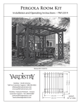
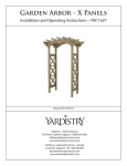
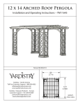
Installation Manual
Privacy Screen with Planters
YM11615
Yardistry
Mount Forest, ON Canada N0G 2L0
Toll Free Customer Support: 1.888.509.4382
[email protected]
www.yardistrystructures.com
Revised 01/23/2013
1
Important Safety Notice!
•
Yardistry components are intended for privacy, decorative and ornamental use only.
Product is NOT INTENDED for the following:
- A safety barrier to prevent unsupervised access to pools, hot tubs, spas, or ponds.
- Safety railings for elevated platforms or decks.
- As load bearing support for a building, structure, heavy objects or swings.
- Used in structures that trap wind, rain or snow that would create extra load on the product.
Wood is NOT flame retardant and will burn. Grills, fire pits and chimineas are a fire hazard if placed too close
to a Yardistry structure. Consult user’s manual of the grill, fire pit or chimnea for safe distances from combustible
materials.
Wear gloves to avoid injury from possible sharp edges of individual elements before assembly.
During installation, follow all safety warnings provided with your tools and use OHSA approved safety
glasses. Some structures may require two or more people to install safely.
Limited Warranty
Yardistry warrants that this product is free from defect in materials and workmanship
for a period of one year from the original date of purchase. In addition, all lumber is
warranted for 5 years against rot and decay. This warranty applies to the original owner
and registrant and is non-transferable.
Regular maintenance is required to assure the integrity of your product and is a requirement of
the warranty. This warranty does not cover any inspection cost.
This Limited Warranty does not cover:
•
Labor for replacement of any defective item(s);
•
Incidental or consequential damages;
•
Cosmetic defects which do not affect performance or integrity;
•
Vandalism; improper use or installation; acts of nature;
•
Actsofnatureincludingbutnotlimitedtowind,storms,hail,floods,excessivewater
exposure;
•
Minor twisting, warping, checking, or any other natural occurring properties of wood that
do not affect performance or integrity.
Yardistryproductshavebeendesignedforsafetyandquality.Anymodificationsmadetothe
original product could damage the structural integrity of the product leading to failure and
possibleinjury.Yardistrycannotassumeanyresponsibilityformodifiedproducts.Furthermore,
modificationvoidsanyandallwarranties.
This product is warranted for RESIDENTIAL USE ONLY. Yardistry disclaims all other
representations and warranties of any kind, express or implied.
This Warranty gives you specific legal rights. You may have other rights as well which vary from state to state or province to
province. This warranty excludes all consequential damages, however, some states do not allow the limitation or exclusion of
consequential damages, and therefore this limitation may not apply to you.
2
Instructions for Proper Maintenance
Your Yardistry structure is designed and constructed of quality materials. As with all outdoor products it
will weather and wear. To maximize the enjoyment, safety and life of your structure it is important that
you, the owner, properly maintain it.
HARDWARE:
•
•
•
Check metal parts for rust. If found, sand and repaint using a non-lead paint complying with 16
CFR 1303.
Inspect and tighten all hardware after completion of assembly; after first month of use; and then
annually. Do not over-tighten as to cause crushing and splintering of wood.
Check for sharp edges or protruding screw threads, add washers if required.
WOOD PARTS:
•
•
Unprotected they will appear weathered over time. Periodic application of an exterior water
repellent or stain (water-based) will help improve appearance and life.
Check all wood members for deterioration, structural damage and splintering. Sand down
splinters and replace deteriorated wood members. As with all wood, some checking and small
cracks in grain is normal.
General Information
General Information: Wood components are manufactured with Cedar (C. Lanceolata)
which is protected with factory applied water-based stain. Knots, small checks (cracks)
and weathering are naturally occurring and do not affect the strength of the product.
Annual application of a water-based water repellent sealant or stain will help reduce
weathering and checks.
www.yardistrystructures.com
Questions?
Call toll free or write us at:
1 (888) 509-4382
[email protected]
Patents Pending
• Tape Measure
• Standard or Cordless Drill
for Driver Bits.
Tools Required
• Phillips/Robertson Driver Bit or
screwdriver
• Safety Glasses
3
• Gloves
are approximate and are shown to assist in the identification of parts for assembly.
Part Identification ( Dimensions
)
Actual dimensions may be smaller or larger.
018
020
019
1pc. - Planter Screen B - Y70119-020
38.1 x 520.7 x 1676.4mm
1pc. - Planter Screen AL - Y70119-018
38.1 x 520.7 x 1676.4mm
1pc. - Planter Screen AR - Y70119-019
38.1 x 520.7 x 1676.4mm
016
017
4pc. - Inside Wall - Planter Box - Y70119-017
38.1 x 250.8 x 419.1mm
4pc. - Outside Wall - Planter Box - Y70119-016
38.1 x 250.8 x 417.5mm
143
142
2pc. - Base Board End - Y50119-142
15.9 x 103.3 x 385.8mm
4pc. - T&G Base Board - Y50119-143
15.9 x 109.6 x 385.8mm
136
134
16pc. - Frame Rail - Adjustable - Y50119-134
19.1 x 38.1 x 163.5mm
2pc. - T Base Board - Y50119-136
15.9 x 109.6 x 385.8mm
133
135
4pc. - End Support - Y50119-135
19.1 x 38.1 x 341.3mm
8pc. - Frame Stile - Y50119-133
19.1 x 63.5 x 250.8mm
146
2pc. - Base Support - Y50119-146
38.1 x 38.1 x 379.4mm
4
Hardware Identification (
Dimensions are approximate and are shown to assist in the identification of parts for
assembly. Actual dimensions may be smaller or larger.
56pc. - Wood Screw #6 x 1-1/8" - (Y06420-914)
32pc. - Pan Screw #6 x 5/8" - (Y06420-908)
48pc. - Wood Screw #8 x 1-1/2" - (Y06420-512)
12pc. - Wood Screw #10 x 1" - (Y06420-710)
16pc. - Wood Screw #8 x 2-1/2" - (Y06420-522)
12pc. - Wood Screw #8 x 3" - (Y06420-530)
8pc. - Corner Brace - Planter Box
(Y70890-005)
6pc. - Hinge - Planter Screen
(Y00419-014)
Accessory Identification(ReducePartSize)
1pc. - #2 x 2" Robertson Driver
(9200014)
2pc. - Box Liner
(Y61800-002)
5
)
Step 1- Attach inside Walls
A. Attach 1 (142) Base Board End to the ledge of the (017) Inside Wall Assemblies, using 4 (YS27)
#6 x 1-1/8” wood screws as shown below. Be sure it is flush to the edge. (Fig. 1.1 and 1.2)
B. Attach 2 (143)T&G Base Board to the ledge of the (017) Inside Wall Assemblies, using 4 (YS27)
#6 x 1-1/8” wood screws per board. (Fig. 1.1)
C. Attach 1 (136) T Base Board to the ledge of the (017) Inside Wall Assemblies, using 4 (YS27) #6
x 1- 1/8” wood screws per board. Be sure it is flush to the edge. (Fig. 1.1 and 1.2)
Repeat for 2 assemblies
Fig. 1.1
017
YS27
x 16
142
136
017
143
Fig. 1.2
Flush, both ends
2
2
4
4
x
x
x
x
136
142
017
143
T Base Board (15.9 x 109.6 x 385.8 mm)
Base Board End (15.9 x 103.3 x 385.8 mm)
Inside Wall Assembly (38.1 x 250.8 x 419.1mm)
T&G Base Board (15.9 x 109.6 x 385.8 mm)
32 x YS27 #6 x 1-1/8” Wood Screw
6
Step 2 - Attach outside walls
A. Flush to the outside of (017) Inside Wall Assembly, attach 2 (016) Outside Wall Assembly using 4
(YS3) #8 x 2-1/2” wood screws per assembly as shown below.
Repeat for 2 assemblies
Flush to outside of Inside Wall Assembly
017
Notice hole location.
YS3
x8
016
Flush to outside of (017)
Inside Wall Assembly
4 x
016
16 x YS3 #8 x 2-1/2” Wood Screw
Outside Wall Assembly (38.1 x 250.8 x 417.5 mm)
7
Step 3 - Attach supports to box
A. Place 2 (135) End Supports and 1 (146) Base Support as shown in Fig. 3.1 and attach using 1
(YS4) #8 x 3” wood screw through each (016) Outside Wall Assemblies. (Fig. 3.1)
B. Then from the inside of the box, secure with 8 (YS27) #6 x 1-1/8” wood screws. (Fig. 3.2)
Repeat for 2 assemblies
Fig. 3.1
May have to loosen these
screws for the supports to fit
146
YS4
Fig. 3.2
YS4
YS27
Underneath View
x3
135
YS27
YS27
x 3 (2 corner screws hidden)
142
143
136
Inside View
4 x
2 x
135
146
End Support (19.1 x 38.1 x 341.3 mm)
Base Support (38.1 x 38.1 x 379.4 mm)
8
4x
YS4
16 x
YS27
#8 x 3” Wood Screw
#6 x 1-1/8” Wood Screw
Step 4 - Attach Frame stiles to box
A. Attach 4 (133) Frame Stiles flush to the edge of (016) Outside Wall Assembly using 2 (YS2) #8 x
1-1/2” Wood Screws per Frame Stile.
B. Secure the (017) Inside Wall Assemblies to the (133) Frame Stile from the inside using 4 (YS27)
#6 x 1-1/8” wood screws.
Repeat for 2 assemblies
016
Flush to edge of
Outside Wall Assembly
016
016
Flush to edge of
Outside Wall Assembly
133
x4
YS27
x4
YS2
016
8 x
133
Frame Stile (19.1 x 63.5 x 250.8 mm)
9
x8
8 x
YS27
#6 x 1-1/8” Wood Screw
16 x
YS2
#8 x 1-1/2” Wood Screw
Step 5 - Attach corner braces
A. Attach 4 (005) Corner Braces to each (017) Inside Wall Assembly and (016) Outside Wall
Assembly as shown below. Use 4 (YS13) #6 x 5/8” Pan Screws per (005) Corner Brace, ensuring
that they are flush to the bottom.
Repeat for 2 assemblies
YS13
x 16
Corner Brace - Planter Box
Flush to bottom
32 xYS13 #6 x 5/8” Pan Head Screw
8 x Corner Brace
10
Step 6 - assemble screens
A. Before assembling the screens, determine what the final orientation will be.
B. Place 2 of the screens side by side as shown in Fig. 6.1 and 6.2, and attach 3 Hinges to the
Planter Screens using 2 (YS28) #10 x 1” Wood Screws per hinge. Ensure that the hinges are flush
to the edge of the groove. Repeat on opposite side. Keep in mind that the hinge pivot is to be
located on the same side that the screen opens toward. (Fig. 6.3)
018
020
019
Fig. 6.1
Fig. 6.2
014
Note: 2 Hinge locations
Flush to edge of groove
The hinge pivot is to be
located on the same side that
the screen opens towards
YS28
Fig. 6.3
x6
The planter screen is very versatile.
The image above is another example
of how to place your hinges.
1
1
1
6
x
x
x
x
018
020
019
014
Planter Screen AL (38.1 x 520.7 x 1676.4 mm)
Planter Screen B (38.1 x 520.7 x 1676.4 mm)
Planter Screen AR (38.1 x 520.7 x 1676.4 mm)
Hinge - Planter Screen
12 x
11
YS28
#10 x 1” Wood Screw
Step 7 - Attach Planter Box
A. Determine Planter Box orientation.
B. Install Planter Box Rails according to desired orientation.
C. Once you decide which orientation you will be using (i.e Planter Box Centred or Planter Box
Offset), attach 8 (134) Frame Rail to the (017) Inside Assemblies as shown below, using 2 (YS2) #8
x 1-1/2” wood screws per Frame Rail Adjustable.
Planter Box Centred
Note: Frame Rail Adjustable must be flush to
both Frame Stile as shown.
Leave 1-5/8” in between Frame Rail Adjustable.
Planter Box Offset
Note: Frame Rail Adjustable must be
flush to one Frame Stile as shown.
Leave 1-5/8” at opposite end of assembly.
1-5/8”
1-5/8”
Flush to Stile,
both sides
134
134
x8
x8
YS2
x 16 per box
16 x 134 Frame Rail Adjustable (19.1 x 38.1 x 163.5 mm)
Flush to Stile,
one side
32 X YS2 #8 x 1-1/2” Wood Screw
12
Step 8 - Attach Planter Boxes to Planter Screens
And Place Box Liner
1. Attach Planter Boxes to Planter Screens using 4 (YS4) #8 x 3” Wood screws per Planter Box as
shown below.
2. Place 1 Box Liner into each assembled Planter Box. Be sure to note that the shoulder on the box
liner fits under the Panel Rails.
Note: Fill with dirt immediately to prevent wind blow over.
YS4
4 per Planter Box
Box Liner
The shoulder on the box liner
fits under the panel rails.
8 x
YS4
#8 x 3” Wood Screw
13
2 x Box Liner