1
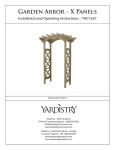
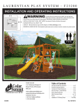
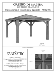
12 x 14 Arched Roof Pergola
Installation and Operating Instructions – YM11645
12 x 14 Arched Pergola Room
YM11645
Revised 04/08/2013
12ft
3.7 M
Yardistry – North America
Toll Free Customer Support: 1.888.509.4382
[email protected]
www.yardistrystructures.com
14 ft
4.73M
Yardistry / Selwood Products – Europe
Customer Support: +44 1284 852569
[email protected]
www.selwoodproducts.com
HEIGHT:
8’ 8or 2.63m
1
[email protected]
Important Safety Notice!
Yardistry components are intended for privacy, decorative and ornamental use only.
Product is NOT INTENDED for the following:
•A
safety barrier to prevent unsupervised access to pools, hot tubs, spas or ponds.
• As load bearing support for a building, structure, heavy objects or swings.
•U
sed in structures that trap wind, rain or snow that would create extra load on the
product.
Permanent structures may require a building permit. As the purchaser and or installer
of this product you are advised to consult local planning, zoning and building inspection
departments for guidance on applicable building codes and/or zoning requirements.
Wood is NOT flame retardant and will burn. Grills, fire pits and chimineas are a fire
hazard if placed too close to a Yardistry structure. Consult user’s manual of the grill, fire
pit or chimnea for safe distances from combustible materials.
Wear gloves to avoid injury from possible sharp edges of individual elements before
assembly.
During installation, follow all safety warnings provided with your tools and use
OHSA approved safety glasses. Some structures may require two or more people to
install safely.
Check for underground utilities before digging or driving stakes into the ground!
.
General Information
General Information: Wood components are manufactured with Cedar (C. Lanceolata)
which is protected with factory applied water-based stain. Knots, small checks (cracks)
and weathering are naturally occurring and do not affect the strength of the product.
Annual application of a water-based water repellent sealant or stain will help reduce
weathering and checks.
www.yardistrystructures.com
Questions?
Call toll free or write us at:
1 (888) 509-4382
[email protected]
Patents Pending
2
[email protected]
Limited Warranty
Yardistry warrants that this product is free from defect in materials and workmanship
for a period of one year from the original date of purchase. In addition, all lumber is
warranted for 5 years against rot and decay. This warranty applies to the original owner
and registrant and is non-transferable.
Regular maintenance is required to assure the integrity of your product and is a requirement of
the warranty. This warranty does not cover any inspection cost.
This Limited Warranty does not cover:
•
Labor for replacement of any defective item(s);
•
Incidental or consequential damages;
•
Cosmetic defects which do not affect performance or integrity;
•
Vandalism; improper use or installation; acts of nature;
•
Actsofnatureincludingbutnotlimitedtowind,storms,hail,floods,excessivewater
exposure;
•
Minor twisting, warping, checking, or any other natural occurring properties of wood that
do not affect performance or integrity.
Yardistryproductshavebeendesignedforsafetyandquality.Anymodificationsmadetothe
original product could damage the structural integrity of the product leading to failure and
possibleinjury.Yardistrycannotassumeanyresponsibilityformodifiedproducts.Furthermore,
modificationvoidsanyandallwarranties.
This product is warranted for RESIDENTIAL USE ONLY. Yardistry disclaims all other
representations and warranties of any kind, express or implied.
This Warranty gives you specific legal rights. You may have other rights as well which vary from state to state or province to
province. This warranty excludes all consequential damages, however, some states do not allow the limitation or exclusion of
consequential damages, and therefore this limitation may not apply to you.
3
[email protected]
Instructions for Proper Maintenance
Your Yardistry structure is designed and constructed of quality materials. As with all outdoor
products it will weather and wear. To maximize the enjoyment, safety and life of your structure
it is important that you, the owner, properly maintain it.
HARDWARE:
• Check metal parts for rust. If found, sand and repaint using a non-lead paint complying
with 16 CFR 1303.
• Inspect and tighten all hardware after completion of assembly; after first month of use; and
then annually. Do not over-tighten as to cause crushing and splintering of wood.
• Check for sharp edges or protruding screw threads, add washers if required.
WOOD PARTS:
• Unprotected they will appear weathered over time. Periodic application of an exterior
water repellent or stain (water-based) will help improve appearance and life.
• Check all wood members for deterioration, structural damage and splintering. Sand down
splinters and replace deteriorated wood members. As with all wood, some checking and
small cracks in grain is normal
Assembly Guides
Tools Required:
•
•
•
•
•
Tape Measure
Carpenters Level
Standard or Cordless Drill
#2 Phillips Bit or Screwdriver
7/16” Wrench or Socket
•
•
•
•
•
8’ Step Ladder
Safety Glasses
Adult Helper
Gloves
Hard Hat
Symbols:
Throughout these instructions symbols are provided in the top, right-hand corner of the page.
•
Use Help, where this is shown, 2 or 3 people
are required to safely complete this step.
To avoid injury or damage to the assembly
make sure to get some help.
•
Pre-drill a pilot hole before fastening
screw or lag to prevent splitting of wood.
•
Use a measuring tape to assure proper
location
If you dispose of your Yardistry structure: Please disassemble and dispose of your
unit so that it does not create any unreasonable hazards at the time it is discarded. Be
sure to follow your local waste ordinances.
4
[email protected]
Permanent Installation Examples
Note: It is critically important you start with square, solid and level footings, concrete
pad or deck to attach your Pergola Room.
We supply Room L-Mounts with this structure which gives you the flexibility to permanently install your
structure to a pre-existing or new wood or concrete surface.
• The hardware to attach the Room L-Mount to the structure is included.
• The hardware to mount the structure permanently will need to be purchased separately at your local
hardware store.
If you are mounting to concrete footers see below for the correct locations and placement. Please double
check for possibility of any underground utilities such as gas, telephone, cable or sprinkler lines.
Following are some examples of how to mount the structure to wood or concrete surfaces.
Refer to your local building and city codes, ordinances, neighbourhood covenants, or height restrictions
regarding this type of structure for guidance on accepable installation requirements.
Concrete Footer
16 1/8” - Groove
2 3/4” 1”
Room L - Mount
Room L - Mount
#10 x 1-1/4” Pan Screws Included
Corner Post
11/2”
Panel Post
Anchoring Hardware not included
Panel Post
To
Required
Depth
120"
120"
78 1/2"
169 11/16"
78 1/2"
20 3/4"
5
[email protected]
Permanent Installation Examples cont.
Concrete Patio (min. 10’ 2” x 10’ 2”) with 12” clearance on all sides
#10 x 1-1/4” Pan Screws Included
Anchoring Hardware not included
Wood Deck (min. 10’ 2” x 10’ 2”) with 12” clearance on all sides
#10 x 1-1/4” Pan Screws Included
Anchoring Hardware not included
Post
#10 x 1-1/4”
Pan Screw
Room L-Mount
6
[email protected]
7
[email protected]
Beam End
10-1/2" (069)
Engineered Panel Corner Post Long (239)
Bottom Brace Insert (191)
Engineered Panel Post Long (241)
X Insert (183)
Horizontal Insert (185)
Cross Brace Insert (189)
Arch Gusset Right (193)
Trellis End Long (232)
Arch Gusset Left
(194)
Beam Hanger
2 x 3 Trellis Clip
Support Beam 105-1/2" (231)
Beam 105-1/2" (234)
Plinth Long Assembly (026)
Arch Gusset Left Long(236)
Plinth End Assembly (029)
Plinth Short B Assembly (028)
Plinth Short A Assembly (027)
L Mount Left
L Mount Right
Arch Gusset Right
Long (237)
Corner Post Long
(235)
Trellis End Short (233)
Arch Beam Centre (079)
Arch Beam Front (195)
Arch Beam Offset (080)
Beam 20-3/4" (067)
Beam End 34-1/4" (192)
are approximate and are shown to assist in the identification of parts for
Part Identification ( Dimensions
)
assembly. Actual dimensions may be smaller or larger.
38.1 x 38.1 x 409.6mm
32pc. (185) - Horizontal Insert 2 x 2 x 16-1/8" - Box 1
38.1 x 38.1 x 574.7mm
64pc. (183) - X Insert 2 x 2 x 22-5/8" - Box 1,2,3
38.1 x 63.5 x 1699.7mm
9pc. (233) - Trellis End Short 2 x 3 x 66 15/16" - Box 2
38.1 x 63.5 x 2554.8mm
9pc. (232) - Trellis End Long 2 x 3 x 100 -5/8 - Box 1
38.1 x 76.2 x 409.6mm
8pc. (189) - Cross Brace Insert 2 x 4 x 16-1/8" - Box 3
36 x 69.9 x 2463.8mm
8pc. (241) - Engineered Panel Post Long 2 x 4 x 97" - Box 2
53.5 x 69.9 x 2463.8mm
8pc. (239) - Engineered Panel Corner Post Long 2 x 4 x 97" - Box 2
36 x 127 x 453.2mm
2pc. (193) - Arch Gusset Right 2 x 5 x 17-27/32" - Box 3
36 x 127 x 453.2mm
2pc. (194) - Arch Gusset Left 2 x 5 x 17-27/32" - Box 3
38.1 x 139.7 x 266.7mm
4pc. (069) - Beam End 10-1/2" 2 x 6 x 10-1/2" - Box 3
38.1 x 69.9 x 408.9mm
8pc. (191) - Bottom Brace Insert 2 x 4 x 16-1/8" - Box 3
36 x 139.7 x 762mm
2pc. (236) - Arch Gusset Left Long 2 x 6 x 30" - Box 1
36 x 139.7 x 762mm
2pc. (237) - Arch Gusset Right Long 2 x 6 x 30" - Box 1
8
[email protected]
Part Identification (
)
Dimensions are approximate and are shown to assist in the identification of parts for
assembly. Actual dimensions may be smaller or larger.
38.1 x 139.7 x 527.1mm
4pc. (067) - Beam 20-3/4" 2 x 6 x 20-3/4" - Box 3
38.1 x 139.7 x 870mm
4pc. (192) - Beam End 34-1/4" 2 x 6 x 34-1/4" - Box 3
38.1 x 139.7 x 1866.9mm
4pc. (231) - Support Beam 2 x 6 x 73-1/2" - Box 2
38.1 x 241.3 x 3048.0mm
2pc. (195) - Arch Beam Front - Box 3
38.1 x 241.3 x 3048.0mm
2pc. (080) - Arch Beam Offset - Box 3
38.1 x 241.3 x 3048.0mm
2pc. (079) - Arch Beam Centre - Box 3
38.1 x 139.7 x 2679.7mm
2pc. (234) - Beam 105-1/2" 2 x 6 x 105-1/2" - Box 1
69.9 x 69.9 x 2463.8mm
4pc. (235) - Corner Post Long 3 x 3 x 97" - Box 2
34.9 x 152.4 x 492.1mm
4pc. (027) - Plinth Short A Assemlby - Box 1
34.9 x 152.4 x 141.3mm
8pc. (029) - Plinth End Assembly - Box 1
34.9 x 152.4 x 492.1mm
4pc. (028) - Plinth Short B Assembly - Box 1
34.9 x 152.4 x 598.5mm
8pc. (026) - Plinth Long Assembly - Box 1
9
[email protected]
Hardware Identification (
Dimensions are approximate and are shown to assist in the identification of
parts for assembly. Actual dimensions may be smaller or larger.
)
9pc. H2 - Hex Bolt 1/4 x 2" - (Y07416-920)
4pc. G10 - Hex Bolt 5/16 x 3" - (Y07416-330)
4pc. G5 - Hex Bolt 5/16 x 4-1/2" - (Y07416-342)
8pc. G22 - Hex Bolt 5/16 x 5" - (Y07416-350)
4pc.
z
- Hex Bolt 5/16 x 6" - (Y07416-360)
1pc. - 1/8" Drill Bit
(Y00400-002)
94pc. - S12 Pan Screw #10 x 1-1/4" - (Y06416-911)
113pc. S24 - Wood Screw #10 x 4" - (Y06416-940)
152pc. S4 - Wood Screw #8 x 3" - (Y06416-530)
90pc. S3 Wood Screw #8 x 2 1/2" - (Y06416-522)
96pc. - TS Trim Screw #6 x 30mm - (Y06416-930)
1pc. D4 - #2 x 2" Roberston Driver (9200014)
9pc. - 1/4" Lock Nut
(Y08416-202)
18pc. FW1 - 1/4" Flat Washer
(Y05416-201)
20pc. LW2 - 5/16" Lock Washer
(Y05416-300)
1pc. YP1 - X Insert Pin
(Y70814-001) (34 PK)
20pc. FW2 - 5/16" Flat Washer
20pc. TN2 - 5/16 - T-Nut
(Y08416-300)
(Y05416-203)
10
[email protected]
Hardware Identification (
Dimensions are approximate and are shown to assist in the identification of
parts for assembly. Actual dimensions may be smaller or larger.
8p
c.
8p
c.
-
LM
ou
nt
Le
ft
- (Y
00
41
9-0
04
)
LM
ou
nt
)
Rig
ht
- (Y
00
41
9-0
05
)
9 pc. - 2 x 3 Trellis Clip
(Y00413-001)
4 pc. - Beam Hanger
(Y00413-011)
11
[email protected]
Step 1: Inventory Parts - Read This Before Starting Assembly
STOP
STOP
STOP
STOP
A. This is the time for you to inventory all your hardware, wood and accessories,
referencing the parts identification sheets. This will assist you with your assembly.
• Each step indicates which bolts and/or screws you will need for assembly, as well as
any flat washers, lock washers, t-nuts or lock nuts.
B. If there are any missing or damaged pieces or you need assistance with
assembly please contact the consumer relations department directly. Call us
before going back to the store.
1-888-509-4382
[email protected]
C.Read the assembly manual completely, paying special attention to ANSI warnings;
notes; and safety/maintenance information on pages 1 - 4.
• F
ollow the instructions in order.
•T
his structure is designed to be assembled and installed ideally by two people,
• Consider the slope of elevation where you plan to install the structure. Also, check for
gas, telephone, other utilities or sprinkler line locations prior to excavating any holes.
DO NOT attempt to install alone.
D.Before you discard your cartons fill out the form below.
• The carton I.D. stamp is located on the end of each carton.
• Please retain this information for future reference. You will need this information if you
contact the Consumer Relations Department.
PRODUCT NUMBER: YM11645
CARTON I.D. STAMP: __ __ __ __ __ ___ (Box 1)
CARTON I.D. STAMP: __ __ __ __ __ ___ (Box 2)
CARTON I.D. STAMP: __ __ __ __ __ ___ (Box 3)
12
[email protected]
Step 2: Assemble “X” Inserts
A: Place one X Insert Pin into one X Insert, then attach a second X Insert to form a complete Insert. Make sure
the pieces are tight to each other.
B: Repeat Step A to make 32 complete Inserts.
Fig. 2.1
X Insert Pin
X Insert
Wood Parts
Hardware
64 x X Insert 38.1 x 38.1 x 574.7 mm
32 x X Insert Pin
13
[email protected]
Step 3: Assemble 8 Panels
Part 1
Fig. 3.1
(241)
Engineered
Panel Post
Long
Top
Note: You will be assembling 8 Panel Post Assemblies in
total in Step 3.
A: Lay one (241) Engineered Panel Post Long and one (239)
Engineered Panel Corner Post Long on edge so the grooved
sides face each other, on a level surface.
(239) Engineered
Panel Corner Post
Long
B: Place one (191) Bottom Brace Insert in between the posts
tight to the bottom ledge and attach with two #8 x 3” Wood
Screws as shown in fig. 3.1.
C: Set one (185) Horizontal Insert between the posts and
tight to Bottom Brace Insert. Attach with two #8 x 3” Wood
Screw as shown in figure 3.1.
(185) Horizontal Insert
#8 x 3” Wood
Screws
Tight to
bottom
ledge on
both posts
Wood Parts
8
8
8
8
x
x
x
x
(191) Bottom
Brace Insert
#8 x 3” Wood
Screws
Bottom
Hardware
(241) Engineered Panel Post Long 36 x 69.9 x 2463.8 mm
(191) Bottom Brace Insert 38.1 x 69.9 x 409.6 mm
(185) Horizontal Insert 38.1 x 38.1 x 409.6 mm
(239) Engineered Panel Corner Post Long 53.5 x 69.9 x 2463.8 mm
32 x #8 x 3” Wood Screw
14
[email protected]
Step 3: Assemble 8 Panels
Part 2
Fig. 3.2
D: Slide one complete Insert in from
the top of the panels and down to the
(185) Horizontal Insert. (fig. 3.2)
(241)
Engineered
Panel Corner
Post Long
Fig. 3.3
#8 x 3”
Wood
Screws x 5
E: Slide one (185) Horizontal Insert to
the top of the complete Insert. (fig. 3.2)
Attach with two #8 x 3” Wood Screws.
(189) Cross
Brace Insert
#8 x 3”
Wood
Screws x 5
Note: Be sure to maintain 16”
measurement between each (185)
Horizontal Insert. (fig 3.3)
(239)
Engineered
Panel Corner
Post Long
F: Repeat Steps D and E so there are
four complete Inserts per Panel Post
assembly. The last board should be
a (189) Cross Brace Insert. Attach all
three Horizontal Inserts with two #8 x
3” Wood Screws per insert and attach
(189) Cross Brace Insert with four #8 x
3” Wood Screws. (fig. 3.3)
(185)
Horizontal
Insert
(185)
Horizontal
Insert
Complete
Insert
16”
(185)
Horizontal
Insert
(191) Bottom
Brace Insert
Wood Parts
Hardware
32 x Completed Inserts from Step 2
8 x (189) Cross Brace Insert 38.1 x 76.2 x 409.6 mm
24 x (185) Horizontal Insert 38.1 x 38.1 x 409.6 mm
80 x #8 x 3” Wood Screw
15
[email protected]
Step 4: Attach Panel Posts to Corner Posts
Part 1
Fig. 4.1
(241)
Engineered
Panel Post
Long
(239)
Engineered
Panel Corner
Post Long
Note: Only pre-drill one post per
assembly
A: On (239) Engineered Panel Corner Post Long, per assembly, pre-drill
two holes from the inside, at the places
shown in fig. 4.1 and 4.2. Pre-drill in the
centre of the panel and on a slight angle.
Fig. 4.2
Pre-drill
on a slight
angle
pre-drill 3 holes from the centre
on a slight angle
16
[email protected]
Step 4: Attach Panel Posts to Corner Posts
Part 2
Fig. 4.3
#8 x 2-1/2”
Wood
Screws
B: Through the pre-drilled holes attach two
Panel Posts assemblies to one (235) Corner
Post Long with one #10 x 4” Wood Screw per
Panel Post Assembly at bottom and six #8 x
2-1/2” Wood Screws along post as shown in
fig. 4.3.
(235)
Corner
Post Long
#8 x 2-1/2”
Wood
Screws
Complete this step for all four Corner
Posts.
#8 x 2-1/2”
Wood
Screws
Flush
#10 x 4”
Wood
Screws
Wood Parts
Hardware
4 x (235) Corner Post Long 69.9 x 69.9 x 2463.8 mm
8 x #10 x 4” Wood Screw
24 x #8 x 2-1/2” Wood Screw
17
[email protected]
Step 5: Attach L - Mount Brackets
A: Pre-drill with a 1/8” drill bit and attach two L Mounts (one L Mount Right and one L Mount Left) flush to the
inside edge, at the bottom of each Panel Post with two #10 x 1-1/4” Pan Screw per L Mount as shown in fig.
5.1, 5.2 and 5.3.
Fig. 5.1
Fig. 5.3
L Mount Right
Note orientation of tabs.
#10 x 1-1/4” x 2 per L Mount
Pan Screw
L Mount Right
Note: Flush to the inside edge.
L Mount Left
Fig. 5.2
L Mount Left
L Mount Right
L Mount Left
Flush to bottom of posts
Hardware
16 x Room L-Mount (Right and Left)
32 x #10 x 1-1/4” Pan Screw
18
[email protected]
Step 6: Attach Plinths to Corner Post Assembly
Part 1
A: Place one (028) Plinth Short B Assembly with one (027) Plinth Short A Assembly tight to each other and
attach using two #6 x 30 mm Trim Screw at the opposite corners per Plinth. (Fig. 6.1 and 6.2)
Note: Plinths will be attached to four corners.
Fig. 6.1
Plinths rest on top of the L Mounts
Flush to corners
Fig. 6.2
(028) Plinth Short
B Assembly
(027) Plinth Short
A Assembly
#6 x 30 mm
Trim Screw
Wood Parts
Hardware
4 x (027) Plinth Short A Assembly 34.9 x 152.4 x 492.1 mm
4 x (028) Plinth Short B Assembly 34.9 x 152.4 x 492.1 mm
16 x #6 x 30 mm Trim Screw
19
[email protected]
Step 6: Attach Plinths to Corner Post Assembly
Part 2
B: On the outside of the corner post assembly, place two (026) Plinth Long Assembly tight against eachother
using 2 #6 x 30 mm Trim Screws per Plinth. Be sure they are flush and tight. (Fig. 6.3 and 6.4)
Fig. 6.3
Fig. 6.4
(026)
Plinth Long
Assembly
#6 x 30 mm
Trim Screw
x 2 per board
Flush
Wood Parts
Hardware
8 x (026) Plinth Long Assembly 34.9 x 152.4 x 598.5 mm
16 x #6 x 30 mm Trim Screw
20
[email protected]
Step 6: Attach Plinths to Corner Post Assembly
Part 3
C: Place one (029) Plinth End Assembly onto each Corner Post Assembly. Line them up with previously placed
Plinths. Make sure they are flush and tight to each other and then fasten with two #6 x 30 mm Trim Screw per
end. (Fig. 6.5 and 6.6)
Fig. 6.5
#6 x 30 mm
Trim Screw
Fig. 6.6
(029) Plinth
End Assembly
(029) Plinth
End Assembly
Flush
#6 x 30 mm
Trim Screw
Note: Loosen screws as
necessary to align all edges.
x 4 per board
Wood Parts
Hardware
8 x (029) Plinth End Assembly 34.9 x 152.4 x 141.3 mm
16 x #6 x 30 mm Trim Screw
21
[email protected]
Step 6: Attach Plinths to Corner Post Assembly
Part 4
Note: Make sure all plinths are lined up, flush and level before installing remaining screws.
D: After the Plinth Ends have been placed, go back and install the two remaining #6 x 30 mm Trim Screws per
end to the assembled Plinth of the Pergola Room. (Fig. 6.7 and 6.8)
E: Attach 2 #6 x 30 mm Trim Screws to each end side as shown in fig. 6.7 and 6.8.
Fig. 6.7
Fig. 6.8
#6 x 30 mm
Trim Screw
Hardware
48 x #6 x 30 mm Trim Screw
22
[email protected]
STEP 4A
Step 7: Locate Corner Post Assemblies
Fig. 7.1
A: Move your Corner Post
Assemblies to the final location.
Make sure the ground is flat and
level before continuing assembly.
B: Stand all four complete
Corner Post Assemblies so they
form a rectangle as shown in fig.
7.1. See figure 7.1 and 7.2 for
accurate placements and additional
measurements.
102 1/2"
78 1/2"
144"
120"
7
187 16 "
Fig. 7.2
78 1/2” x 2
144”
x2
102 1/2” x 2
187 5/16”
C: Depending on what you are placing the Pergola
Room on will determine how you anchor it to that
surface. Please refer to pages 4 and 5 for installation
examples.
Any hardware or extra materials for
mounting will have to be purchased in advance.
120” x 2
23
[email protected]
Step 8: Assemble Beam Ends
Fig. 8.1
10-1/2”
Two Beam Ends
attached on
opposite side of
cut-out
#10 x 4” Wood
Screws
A: On a flat and level surface attach one
(069) Beam End 10-1/2” to (192) Beam
End 34-1/4” with three #10 x 4” Wood
Screws as shown in fig. 8.1.
B: Repeat Step A three more times so
you have four assemblies. Note that two
of the Beam Ends should be on the same
side as the cut out and two should be on
the opposite side. (fig. 8.1 and 8.2)
(192) Beam
End 34-1/4”
Cut-out
(069) Beam
End 10-1/2”
Fig. 8.2
Two Beam
Ends attached
on cut-out side
Cut-out
#10 x 4” Wood
Screws
(192) Beam
End 34-1/4”
10-1/2”
(069) Beam
End 10-1/2”
Wood Parts
Hardware
12 x #10 x 4” Wood Screw
4 x (192) Beam End 34-1/4” 38.1 x 139.7 x 870 mm (2 x 6 x 34-1/4”)
4 x (069) Beam End 10-1/2” 38.1 x 139.7 x 266.7 mm (2 x 6 x 10-1/2”)
24
[email protected]
Step 9: Attach Beams to Corner Post Assemblies
It is important the proper hardware gets
placed in the places shown. You install the
Hex Bolts first and then the screws.
A: Loosely attach one Beam End assembly
from Step 8 to each Corner Post assembly with
the cut-out side facing out using one 5/16 x
5” Hex Bolt (with 5/16” flat washer, 5/16” lock
washer and 5/16” T nut)
Beam End
Assembly
Fig. 9.1
Panel Post
Long
(234) Beam
105 1/2”
5/16 x 5
Hex Bolt
5/16 Lock
Washer
5/16 Flat
Washer
5/16 T-nut
Cut-out
Note: Beams should be flush to top of posts.
5/16 x 6”
Hex Bolt
#8 x 3”
Wood
Screw
Beam End
Assembly
Fig. 9.2
Beam End
Assembly
(234) Beam 105 1/2”
Flush
Flush
B: Fit one (234) Beam 105-1/2”
in between two Corner Post
Assemblies and attach to Beam
End assemblies and Panel Post
as shown in fig. 9.1 and 9.2 with
one 5/16 x 6” Hex Bolt. This bolt
is only used for hole alignment
at this point.
C: Attach six #8 x 3” Wood
Screws.
D: Repeat Steps A, B and C to
the opposite pair of Panel Corner
Post Assemblies to make a front
and back.
Wood Parts
2 x (234) Beam 105-1/2” 38.1 x 139.7 x 2679.7 mm
Hardware
12 x #8 x 3” Wood Screw
4 x 5/16 x 6” Hex Bolt (5/16” flat washer, 5/16” lock washer, 5/16” t-nut)
4 x 5/16 x 5” Hex Bolt (5/16” flat washer, 5/16” lock washer, 5/16” t-nut)
25
[email protected]
Step 10: Attach Arch Beam Fronts
It is important the proper hardware gets
placed in the places shown. Make sure
you install the Hex Bolts first and then the Fig. 10.1
wood screws.
Corner of
Corner Post
Assembly
A: Attach one (195) Arch Beam Front in
between two Corner Post Assemblies as
shown in fig. 10.2 and attach to Corner Post
Assembly with one 5/16 x 5” Hex Bolt (with
5/16” flat washer, 5/16” lock washer and 5/16
t-nut); and one 5/16 x 4 1/2” Hex Bolt (with
5/16” flat washer, 5/16” lock washer and 5/16”
t-nut) per side. (fig. 10.1)
5/16” t-nut
#8 x 3”
Wood
Screw
5/16 x 5”
Hex Bolt5/16” Lock
Washer
5/16” Flat
Washer
B: Attach three #8 x 3” wood screws
per side.
#8 x 3”
Wood
Screw
C: Repeat for the opposite side.
Fig. 10.2
5/16 x 4 1/2”
Hex Bolt
5/16”
5/16” Flat
Lock
Washer Washer
(195) Arch
Beam Front
Outside
Panel Post
(195) Arch
Beam Front
(195) Arch
Beam Front
Wood Parts
2 x (195) Arch Beam Front 38.1 x 241.3 x 3048 mm (2 x 6 x 120”)
Hardware
12 x #8 x 3” Wood Screw
4 x 5/16 x 4-1/2” Hex Bolt (5/16” flat washer, 5/16” lock washer, 5/16” t-nut)
4 x 5/16 x 5” Hex Bolt (5/16” flat washer, 5/16” lock washer, 5/16” t-nut)
26
[email protected]
Step 11: Attach Arch Beam Offsets
It is important the proper hardware gets
placed in the places shown.
A: Attach one (080) Arch Beam Offset
through centre of grooves of Engineered
Panel Post with one #8 x 2-1/2” Wood
Screw and through Beam 81-1/2” with three
#10 x 4” Wood Screws per side shown in fig.
11.1 and 11.2. Complete for two Arch Beam
Offsets.
B: In between Arch Beam Fronts and Arch
Beam Offsets, next to the Engineered Panel
Posts install four (067) Beam 20-3/4” and
attach with one #8 x 2-1/2” Wood Screw and
six #10 x 4” Wood Screws per Beam 20-3/4”
as shown in fig. 11.1 and 11.2.
Arch Beam
Front
Fig. 11.1
#8 x 2-1/2”
Wood
Screw
#8 x 2-1/2”
Wood Screw
#10 x 4” Wood
Screw x 3
#10 x 4”
Wood Screw
x3
Engineered
Panel Post
(068) Beam
81-1/2”
(067) Beam
20-3/4”
Engineered
Panel Post
#10 x 4”
Wood Screw
x3
(080) Arch
Beam Offset
Arch Beam
Front
Fig. 11.2
(067) Beam
20-3/4”
(067) Beam
20-3/4”
(234) Beam
105-1/2”
Arch Beam
Front
(080) Arch
Beam Offset
(067) Beam
20-3/4”
Wood Parts
Hardware
2 x (080) Arch Beam Offset 38.1 x 241.3 x 3048 mm
36 x #10 x 4” Wood Screw
4 x (067) Beam 20-3/4” 38.1 x 139.7 x 527.1 mm
8 x #8 x 2-1/2” Wood Screw
27
[email protected]
Step 12: Attach Arch Beam Centres
Part 1
A: Centre (079) Arch Beam Centres
over the pilot holes in (234) Beam 1051/2” and attach using six #10 x 4” Wood
Screws per side (fig. 12.3 & 12.4)
Fig. 12.3
(079) Arch
Beam Centre
B: Repeat Step C for second (079) Arch
Beam Centre. (fig. 12.4)
#10 x 4” Wood
Screws
(234) Beam
105 1/2”
#10 x 4” Wood
Screws
Fig. 12.4
(234) Beam
105 1/2”
(079) Arch
Beam Centre
#10 x 4” Wood
Screws x 6
per side
Hardware
12 x #10 x 4” Wood Screw
28
[email protected]
Step 12: Attach Arch Beam Centres
Part 2
C: Attach one (079) Arch Beam Centre to
each (234) Beam 105-1/2” using one Beam
Hanger and eleven #10 x 1 1/4” Pan Screw
per Beam Hanger (fig. 12.1 & 12.2)
Fig. 12.1
#10 x 1 1/4”
Pan Screw x
11 per Hanger
(234) Beam
105 1/2”
D: Repeat Step A for second (079) Arch
Beam Centre. (fig 12.2)
Beam Hanger
(079) Arch
Beam Centre
Fig. 12.2
(079) Arch
Beam Centre
Wood Parts
Hardware
2 x (079) Arch Beam Centre 38.1 x 241.3 x 3048 mm
44 x #10 x 1 1/4” Pan Screw
4 x Arch Beam Hanger
29
[email protected]
Step 13: Attach Support Beams
Part 1
A: Leaving the T-nut installed, remove the
5/16 x 6” Hex Bolt (5/16” lock washer and
5/16” flat washer) from each Beam End
Assembly installed in Step 9. (fig. 13.1 &
13.2)
Fig. 13.1
Step 10a
Fig. 13.2
(234) Beam
105 1/2”
Beam End
Assembly
5/16 x 6" Hex Bolt
Remove Hex Blt, Lk Washer, Flat Washer from Step 6
(Leave T-Nut Installed)
5/16 x 6” Hex Bolt
(lock washer and
flat washer)
Hardware
30
[email protected]
Step 13: Attach Support Beams
Part 2
It is important the proper hardware gets placed
in the places shown.
Fig. 13.3
B: Attach one (231) Support Beam to each
Beam End Assembly and (235) Engineered Panel
Corner Post Long by replacing the 5/16 x 6” Hex
Bolt (lock washer and flat washer) removed in
Part 1. (fig 13.3 & 13.4) Ensure the cut outs in the
boards are interlocking as shown in fig. 13.5.
C: Using two 5/16 x 3” Hex Bolts (with lock
washer, flat washer and t-nut) attach the
interlocking cut outs of (231) Support Beams to
(234) Beam 105 1/2” as shown in fig. 13.5.
Fig. 13.4
(235) Engineered
Panel Corner
Post Long
Beam End
Assembly
Fig. 13.5
5/16” t-nut
(231) Support
Beam
5/16 flat washer
(234) Beam
105 1/2”
5/16 flat washer
5/16 lock washer
5/16 lock washer
(231) Support Beam
5/16 x 6” Hex Bolt
(previously removed)
5/16 x 3” Hex Bolt
(231) Support
Beam
Notice board
orientation
Wood Parts
Hardware
4 x 5/16 x 3” Hex Bolt
(5/16 flat washer, 5/16 lock washer, 5/16” T-nut)
4 x 5/16 x 6” Hex Bolt (previously removed)
(5/16 flat washer, 5/16” lock washer & previously installed
5/16” T-nut)
4 x (231) Support Beam 38.1 x 139.7 x 1866.9 mm
31
[email protected]
Step 13: Attach Support Beams
Part 3
Fig. 13.6
D: Attach (231) Support Beams to (234)
Beam 105 1/2” using sixteen #8 x 2 1/2”
Step
Wood Screws per side as shown in fig.13.6
& 13.7.
10C
Fig. 13.7
Fig. 13.7
#8 x 3" WS x12
(234) Beam
105 1/2”
#8 x 2½" WS
x20
(231) Support
Beam
#8 x 2 1/2” Wood
Screws x 16 per side
Hardware
32 x #8 x 2 1/2” Wood Screws
32
[email protected]
Step 14: Assemble Trellis Ends
A: On a flat and level surface, fit together one (233) Trellis End Short and one (232) Trellis End Long.
(fig. 14.1)
B: Place one Trellis Clip over the joined ends and attach with one 1/4 x 2” Hex Bolt (with two 1/4” flat washer and
1/4” lock nut).
(fig. 14.2)
C: Repeat Steps A and B until there are 9 Trellis End Assemblies.
Fig. 14.1
(232) Trellis
End Long
(233) Trellis
End Short
(232) Trellis
End Long
Trellis Clip
1/4” Flat
Washer
Fig. 14.2
1/4” Lock
Nut
1/4” Flat
Washer
(233) Trellis
End Short
1/4 x 2”
Hex Bolt
Wood Parts
Hardware
9 x Trellis Clip
9 x 1/4 x 2” Hex Bolt (1/4”flat washer x 2, 1/4”
lock nut)
9 x (232) Trellis End Long 38.1 x 63.5 x 2554.8 mm
9 x (233) Trellis End Short 38.1 x 63.5 x 1699.7 mm
33
[email protected]
Step 15: Attach Trellis End Assemblies
Part 1
A: Measure 59-1/4” from the inside of each (234) Beam 105-1/2” and place one Trellis End Assembly on the
(080) Arch Beam Offsets, (079) Arch Beam Centres and (195) Arch Beam Fronts. This should be centred and
both ends should hang 9-3/4” over the edges. (fig. 15.1 and 15.4)
B: Attach with five #10 x 4” Wood Screws in the places indicated in fig. 15.1 and 15.2.
C: Attach Trellis Clip to (080) Arch Beam Centre with two #10 x 1-1/4” Pan Screws as shown in fig. 15.1 and
15.3.
#10 x 4”
Wood Screw
Fig. 15.2
(234) Beam
105 1/2”
Fig. 15.1
(080) Arch
Beam
Offset
#10 x 1 1/4”
Pan Screw
Fig. 15.3
Trellis End
Assembly
(080) Arch
Beam
Offset
Trellis Clip
59 1/4”
(195) Arch
Beam
Front
(195) Arch
Beam
Front
59 1/4”
(079) Arch
Beam
Centre
Fig. 15.4
Trellis End
Assembly
Both Sides of Trellis End
Assembly
Arch Beam
Front
9-3/4”
Hardware
5 x #10 x 4” Wood Screw
2 x #10 x 1-1/4” Pan Screw
34
[email protected]
Step 15: Attach Trellis End Assemblies
Part 2
D: Starting at the centre Trellis End Assembly and working outwards attach four Trellis End Assemblies on either
side alternating each Trellis End Assembly so the Trellis Clip is on opposing sides to the assemblies next to it.
(fig. 15.5)
Note: The distance between assemblies should be 12” (fig. 15.6)
Note: Refer to previous page, fig 15.2 and 15.3 for attaching trellis clip.
Fig. 15.5
Start here and move
outwards on either
side alternating trellis
assemblies so Trellis Clip
varies from side to side.
8X
12
Fig. 15.6
8X
12
Hardware
40 x #10 x 4” Wood Screw
16 x #10 x 1-1/4” Pan Screw
35
[email protected]
Step 16: Attach Left and Right Arch Gussets
Part 1
Note: The bevelled ends on each Arch Gusset should always face away from the wood it is attaching to.
A: At two corners of the assembly attach one (194) Arch Gusset Left to the (241) Engineered Panel Post Long
with one #8 x 3” Wood Screws and flush to the inside, bottom edge of the (079) Arch Beam Front with two #8
x 2-1/2” Wood Screws as shown in fig. 16.1 and 16.2. These should be opposing corners. Attach a (193) Arch
Gusset Right on the other two corners.
B: Repeat for opposite side.
Fig. 16.1
Bevelled
End
(079) Arch
Beam Front
Flush
#8 x 2-1/2”
Wood Screw
(194) Arch
Gusset Left
(241)
Engineered
Panel Post
Long
(079) Arch
Beam Front
#8 x 3”
Wood Screw
Fig. 16.2
(194) Arch
Gusset Left
193) Arch
Gusset Right
(241) Engineered
Panel Post Long
Inside view facing out
Pieces removed for clarity
Wood Parts
Hardware
8 x #8 x 2-1/2” Wood Screw
2 x (193) Arch Gusset Right 36 x 127 x 453.2 mm
2 x (194) Arch Gusset Left 36 x 127 x 453.2 mm
4 x #8 x 3” Wood Screw
36
[email protected]
Step 16: Attach Left and Right Arch Gussets
Part 2
Note: The bevelled ends on each Arch Gusset should always face away from the wood it is attaching to.
C: Attach one (237) Arch Gusset Right Long or one (236) Arch Gusset Left Long to the remaining (241) Engineered
Panel Post Longs using two #8 x 3” Wood Screws and to the (234) Beam 105 1/2” with three #8 x 2-1/2” Wood
Screws as shown in fig. 16.3 and 16.4. Each corner of the assembly should have one (237) Arch Gusset Right Long
and one (236) Arch Gusset Left Long.
Bevelled
End
Fig. 16.3
(234) Beam
105 1/2”
#8 x 2-1/2”
Wood Screw
#8 x 3”
Wood Screw
(236) Arch
Gusset Left
Long
#8 x 3”
Wood Screw
Inside view
Fig. 16.4
(241)
Engineered
Panel Post
Long
Wood Parts
Hardware
12 x #8 x 2-1/2” Wood Screw
2 x (237) Arch Gusset Right Long 36 x 139.7 x 762 mm
2 x (194) Arch Gusset Left 36 x 139.7 x 762 mm
8 x #8 x 3” Wood Screw
37
[email protected]
NOTES
38
[email protected]
NOTES
39
[email protected]
YARDISTRY
Consumer Registration Card
First Name
Initial
Last Name
Street
Apt. No.
City
State/Province ZIP/Postal Code
Country
Telephone Number
E-Mail Address
Model Name
Date Purchase
Model Number
(Box Labels)
Purchased From
MM / DD / YY
How would you rate this product for quality?
Excellent Very Good
Average
Below Average
Poor
How would you rate this product for ease of assembly?
Excellent Very Good
Average
Below Average
Poor
How would you rate our instructions?
Excellent Very Good
Average
Below Average
Poor
How would you rate the quality of packaging?
Excellent Very Good
Average
Below Average
Poor
Would you recommend the purchase of our products to friends and family?
Yes
No
MAIL TO:
Yardistry c/o Solowave DesignTM
375 Sligo Road W.
Mount Forest, Ontario, Canada
N0G 2L0
Attention: Customer Service
REVISION: 10/18/11
Yardistry would like to say Thank You for your time and feed-
40
CUT ALONG LINE
Comments:
[email protected]