1
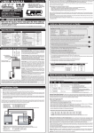
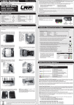
E
AB-58
APPLICATION
BRIEF
28F016XD-Based SIMM
Designs
BRIAN DIPERT
SENIOR TECHNICAL
MARKETING ENGINEER
SUJAN KAMRAN
TECHNICAL MARKETING
ENGINEER
October 1995
Order Number: 292152-002
Intel Corporation makes no warranty for the use of its products and assumes no responsibility for any errors which may appear
in this document nor does it make a commitment to update the information contained herein.
Intel retains the right to make changes to these specifications at any time, without notice.
Contact your local Intel sales office or your distributor to obtain the latest specifications before placing your product order.
MDS is an ordering code only and is not used as a product name or trademark of Intel Corporation.
Intel Corporation and Intel's FASTPATH are not affiliated with Kinetics, a division of Excelan, Inc. or its FASTPATH trademark
or products.
*Other brands and names are the property of their respective owners.
Additional copies of this document or other Intel literature may be obtained from:
Intel Corporation
Literature Sales
P.O. Box 7641
Mt. Prospect, IL 60056-7641
or call 1-800-879-4683
© INTEL CORPORATION 1994
CG-041493
E
1.0
AB-58
INTRODUCTION
This application brief provides design information for
SIMM (Single In-Line Memory Module) configurations
based on the 28F016XD flash memory. The 28F016XD
is an Intel 16-Mbit flash memory component with a
multiplexed address bus hardware interface, compatible
with system DRAM controllers. As such, it is an ideal
high-density flash memory for use in existing designs
with DRAM SIMM connectors, or in new designs where
flexibility in system memory configuration is needed.
The 28F016XD preserves all traditional FlashFile™
memory attributes, including per-bit programmability
and per-block eraseability. Its low power consumption,
full nonvolatility (i.e., no refresh required) and in-system
updateability are desirable attributes in comparison to the
DRAM memory alternative. The 28F016XD supports
both standard and fast page mode reads/writes and all
refresh cycles (which it internally disregards).
The example design explained in detail in this
application brief (Section 2), uses the JEDEC 72-lead
DRAM SIMM standard and supports densities of
1-Mbyte x 32 and 2-Mbyte x 32. Section 3 discusses
ideas for extrapolating this design to other JEDEC
DRAM SIMM pinouts, while Section 4 provides software
guidelines corresponding to flash memory-based SIMM
hardware designs. See Section 6 for additional
information on Intel’s flash memory products.
2.0
72-LEAD SIMM DESIGN
EXAMPLE
Figure 1 shows a full-size layout for the 72-lead SIMM
explained in this section, while Tables 1 and 2 show and
describe the SIMM pinout. Figure 2 shows the SIMM
component interconnect.
MAX706
28F016XD
(Optional)
28F016XD
28F016XD
28F016XD
(Optional)
2152_01
NOTE:
Filter and bypass capacitors not shown.
Figure 1. Flash Memory-Based 72-Lead SIMM (1M x 32 or 2M x 32) with Identical Dimensions and Pinout
as the DRAM-Based Alternative
ADVANCE INFORMATION
1
E
AB-58
Table 1. 72-Lead SIMM Pinout
1
GND
13
A1
25
DQ22
37
NC
49
DQ8
61
DQ13
2
DQ0
14
A2
26
DQ7
38
NC
50
DQ24
62
DQ30
3
DQ16
15
A3
27
DQ23
39
GND
51
DQ9
63
DQ14
4
DQ1
16
A4
28
A7
40
CAS0#
52
DQ25
64
DQ31
5
DQ17
17
A5
29
NC
41
CAS2#
53
DQ10
65
DQ15
6
DQ2
18
A6
30
VCC
42
CAS1#
54
DQ26
66
NC
7
DQ18
19
NC
31
A8
43
CAS3#
55
DQ11
67
PD1
8
DQ3
20
DQ4
32
A9
44
RAS0#
56
DQ27
68
PD2
NC/RAS1#
57
DQ12
69
PD3
(1)
33
NC/RAS3#
(1)
9
DQ19
21
DQ20
45
10
VCC
22
DQ5
34
RAS2#
46
NC
58
DQ28
70
PD4
11
NC
23
DQ21
35
NC
47
W#
59
VCC
71
NC
12
A0
24
DQ6
36
NC
48
NC
60
DQ29
72
GND
NOTES:
1. Pin 33 is a NC for the 1M x 32 SIMM and RAS3# for the 2M x 32 SIMM.
2. Pin 45 is a NC for the 1M x 32 SIMM and RAS1# for the 2M x 32 SIMM.
ADVANCE INFORMATION
2
E
AB-58
Table 2. 72-Lead SIMM Pin Description
Symbol
Type
Name and Function
A0 - A9
INPUT
MULTIPLEXED ROW/COLUMN ADDRESSES: Select a location within the
flash memory array in conjunction with appropriate RAS# and CAS# signals.
Row (upper) addresses are latched on the falling edge of RAS#, while column
(lower) addresses are latched on the falling edge of CAS#.
DQ0 - DQ31
INPUT/
OUTPUT
DATA BUS: Inputs flash memory data and commands during CUI write cycles.
Outputs flash memory array, buffer, identifier or status data in the appropriate
read mode. Floated when the SIMM is de-selected or the outputs are disabled.
RAS0-3#
INPUT
ROW ADDRESS STROBE: Latches row address information on inputs A0-9
when RAS# transitions low. A subsequent CAS# low transition initiates flash
memory read or write operations. RAS0# selects the lower 1M x 32 memory
bank, while RAS1# selects the upper 1M x 32 bank (for the 2M x 32 SIMM).
Signals RAS2# and RAS3# are not used in the design shown in Section 2.
CAS0-3#
INPUT
COLUMN ADDRESS STROBE: Latches column address information on inputs
A0-9 when CAS# transitions low. When preceded by a RAS# low transition,
CAS# low initiates flash memory read or write operations in conjunction with W#.
Subsequent CAS# low transitions, with RAS# held low, enable fast page mode
reads/writes. CAS0# selects the lower 16 bits of a memory bank, while CAS2#
selects the upper 16 bits. Signals CAS1# and CAS3# are not used in the design
shown in Section 2.
W#
INPUT
WRITE ENABLE: Controls access to the CUI, Page Buffers, Data Queue
Registers and Address Queue Latches. W# is active low and initiates writes in
combination with RAS# and CAS# low. W# inactive high with RAS# and CAS#
low signifies a flash memory read operation. RAS# and CAS# high override W#
low.
PD1-4
OUTPUT
PRESENCE DETECT: Indicates SIMM speed/density information for system
identification. Various combinations of PD pins, either connected to GND or left
not connected (pulled high by a resistor on the system board) refer to JEDEC
standards, as indicated in Table 3.
VCC
INPUT
OPERATIONAL AND ERASE/WRITE POWER SUPPLY (5V ± 0.5V). Do not
leave any power pins unconnected. VCC also provides the flash memory VPP
update voltage. The design example in Section 2 does not support operation at
VCC = 3.3V ± 0.3V (see Section 3.4).
GND
SUPPLY
GROUND FOR ALL INTERNAL CIRCUITRY: Do not leave any ground pins
floating.
NC
NO CONNECT: Lead may be driven or left floating.
ADVANCE INFORMATION
3
E
AB-58
GND
SIMM Connector
DQ16-31
Vcc OE# 3/5# DQ0-15
Vcc
Vpp
CAS#
CAS2#
WP# 28F016XD A0-9
(Upper x16)
RY/BY#
RAS#
VccIN
MR#
RP#
WE#
RP#
WE#
A0-9
RAS0#
W#
PWRGOOD
MAX706
Vcc
RY/BY#
RAS#
WP# 28F016XD A0-9
(Lower x16)
Vpp
CAS#
Vcc
Vcc
GND
GND
To Optional
Bank 1
CAS0#
DQ0-15
Vcc OE# 3/5# DQ0-15
RAS1#
GND
BANK 0 (1 Mbyte x 32)
2152_02
Figure 2. The 28F016XD’s Multiplexed Address Bus Interface
Makes DRAM-Compatible SIMM Designs Simple
2.1
Address and Data Bus
The multiplexed address and data buses of all flash
memories are connected together. See the 28F016XD
data sheet (Additional Information, Section 6) for percomponent address and data bus pin capacitance. RAS#,
CAS# and W# control prevents data bus contention
between multiple flash memory components.
2.2
RAS#, CAS#, W#
The 28F016XD is a x16-only flash memory, and each
28F016XD contains one CAS# input. CAS0# connects to
the lower 16-bit component in each 28F016XD bank,
while CAS2# connects to the upper 16-bit component.
Therefore, this interface supports x16 or x32 reads and
writes. RAS0# selects the first 1 Mbyte x 32 bank, while
RAS1# selects the optional second bank. W# from the
SIMM interface connects to all flash memories.
2.3
SIMM Power Pins
VCC from the SIMM interface connects to the VCC and
VPP inputs of all 28F016XD flash memories, and VCC
also connects to the optional supply voltage monitoring
circuit. GND from the SIMM interface connects to all
SIMM component GNDs. This design uses the 5.0V VPP
option of Intel’s SmartVoltage technology. A small
ceramic capacitor filters each flash memory VCC and VPP
input, while a larger decoupling capacitor filters VCC at
the SIMM interface. See Section 3.4 for alternate VCC
and VPP techniques.
2.4
Other 28F016XD Signals
RP# Reset/Power-Down
This design includes an optional low-cost supply voltage
monitoring
circuit
(Maxim
MAX706)
whose
POWERGOOD output controls flash memory RP#
inputs. This scheme protects the flash memory from
ADVANCE INFORMATION
4
E
spurious command writes during system power
transitions. Include the monitoring circuit unless you can
guarantee that your DRAM controller holds the
RAS#/CAS# combination and W# inactive with VCC
above VLKO (see 28F016XD specifications) in all cases
except when intentionally writing to flash memory.
Experience has shown that many memory controllers
have unspecified and unpredictable operation during
system power transitions.
If the monitoring circuit is not used, remove the 8-pin
SOIC layout from the SIMM and connect RP# to VCC.
Alternatively, connect SOIC layout pins corresponding to
the (non-present) monitoring circuit VCC input and
POWERGOOD output, together with a 0-ohm resistor.
AB-58
Detect pin combinations for 4-MB, 8-MB and 16-MB
(x36 72-pin) SIMMs with tRAC = 100 ns are shown in
Table 3. PD combinations for other “non-standard”
speed/density combinations are user definable.
Table 3. PD Signal Combinations for Various
Densities (tRAC = 100 ns)
PD1
PD2
4 MB
GND
GND
GND
GND
8 MB
NC
NC
GND
GND
16 MB
GND
NC
GND
GND
3.0
WP#
This design connects WP# to VCC, driving this input
inactive at all times.
RY/BY#
This design does not use the RY/BY# output, leaving it
disconnected. System software should poll the flash
memory Status Registers to determine device status and
completion of internal operations.
PD3
PD4
RECOMMENDATIONS FOR
DESIGN MODIFICATIONS AND
OTHER SIMM INTERFACES
The 72-lead SIMM interface is only one of several
pinouts approved by JEDEC and other standards bodies.
This section gives recommendations for adapting the
design techniques of Section 2 to other SIMM interfaces.
In addition, it discusses providing voltages other than
5.0V to the 28F016XD SIMM and enhancing system
control of 28F016XD operations.
3.1
Parity
OE#
This design connects OE# to GND. RAS# and CAS#
active, in conjunction with an inactive high W#, initiate a
flash memory read. W# active low overrides the state of
OE#. RAS# and CAS# inactive high override OE# active
low.
3/5#
This design connects 3/5# to GND (for 5V VCC
Operation). This design example does not support
operation at 3.3V VCC (see Section 3.4).
2.5
Other SIMM Signals
PD1-4
PD leads are connected to GND or left unconnected on
the SIMM, and are connected to VCC via pull-up resistors
on the system board. Their state (“1” or “0”), when read
by system logic, provide SIMM speed/density
information and reference the speed bin of the
28F016XD flash memories. JEDEC standard Presence
Flash memory is not subject to the alpha particle soft
errors that plague DRAM, as it stores the data value (“1”
or “0”) intrinsically on the floating gate of the flash
memory transistor. For this reason, a parity output was
not included as part of the 28F016XD pinout. In systems
that employ parity check to confirm the integrity of the
DRAM memory subsystem, on-SIMM programmable or
dedicated logic can generate parity bits required for the
flash memory-based SIMM read interface, if required.
See Figure 3 for an example.
3.2
8-Bit or 9-Bit SIMM Interfaces
The 28F016XD is a x16-only flash memory component.
When used in a x8 or x9 (see Section 3.1) SIMM pinout,
interface logic like that shown in Figure 4 should be used
to route system data to the correct 8 bits of the flash
memory bus and drive the alternate 8 bits to “1”s. System
software must write commands to the flash memory only
on the lower 8 bits for such an interface.
ADVANCE INFORMATION
5
AB-58
3.3
DQ X - Y
RAS#
CAS#
FLASH
MEMORY
ARRAY
PROG.
LOGIC
PARITY
E
Flash Memory Control
Input/Output and VPP Control
SIMMs other than the 72-lead version described in
Section 2 may include additional inputs and outputs that
can provide a system RESET# to the supply voltage
monitoring circuit MR# input. Alternatively, if system
RESET# includes power supply monitoring, this signal
can directly control the 28F016XD RP# inputs.
Additionally, system I/O signals can control the flash
memory WP# input and route the RY/BY# output to a
system port pin or hardware interrupt line. Finally, by
separating out supply and program/erase voltage pins,
alternate or semi-custom SIMM interfaces can provide
12.0V to the 28F016XD flash memory VPP inputs for fast
write performance and switch this program/erase voltage
to GND when not updating flash memory contents for
additional write protection.
W#
2152_03
Figure 3. Parity Generation for DRAM Controller
Compatibility
RAS#
DQ8- 15
PROG.
LOGIC
28F016XD
DQ0-7
PARITY
(OPTIONAL)
W#
VCC and VPP Flexibility
The 28F016XD, by virtue of its SmartVoltage
technology can be operated at either 3.3V or 5.0V VCC,
and at either 5.0V or 12.0V VPP. If 3.3V VCC operation is
desired (for lower power), an on-SIMM 3.3V-to-5.0V
converter can generate the necessary 5.0V VPP voltage.
Some designs may desire to program and erase the
28F016XD at 12.0V VPP for high write performance. In
these cases, include a 5.0V-to-12.0V or 3.3V-to-12.0V
converter on the SIMM to generate the 12.0V VPP
voltage. See application note AP-357 for industryrepresentative 12V-converters.
CAS#
DQ 0-7
3.4
A0
2152_04
Figure 4. Converting the 16-Bit Flash Memory
Data Bus to a x8/x9 System Interface
4.0
SOFTWARE GUIDELINES
System software should not attempt to scan/check the
28F016XD memory space as part of system initialization.
The 28F016XD does not support the DRAM self-check
function. Data combinations written to the 28F016XD
may be decoded as valid commands and result in
unintended flash memory operations. Checksum
calculation and comparison with a checksum data value
stored in the flash memory is a recommended technique
for ensuring data/code integrity.
The hardware interface described in Section 2 allows
only 16- and 32-bit command/data writes to flash
memory. When programming a flash memory location,
set bits not to be programmed to “1”s as part of the data
write. This technique can also be used to mask a write to
the alternate byte of a 16-bit word when performing a
byte program operation.
ADVANCE INFORMATION
6
E
AB-58
The 72-lead SIMM interface of Section 2 does not allow
use of the flash memory RY/BY# output. System
software should poll flash memory Status Registers to
determine status of device operations, including program
and erase.
System software should separate temporary data from
code and “permanent” data tables, and route writes to the
former to the system DRAM memory space. Flash
memory is per-bit programmable (changing data “1”s to
“0”s) and per-block erasable (changing data “0”s to
“1”s), unlike DRAM, which is fully per-bit alterable.
6.0
6.1
5.0
CONCLUSION
This application brief has described one possible SIMM
design using Intel’s 28F016XD Flash memory, and has
provided design recommendations for alternative SIMM
approaches. Consult reference documentation for a more
complete understanding of device capabilities and design
techniques. Please contact your local Intel or distribution
sales office for more information on Intel’s flash memory
products.
ADDITIONAL INFORMATION
References
Order Number
Document/Tool
290533
28F016XD DRAM-Interface Flash Memory Datasheet
297372
"16-Mbit Flash Product Family User's Manual"
292165
AB-62, “Compiled Code Optimizations for Flash Memories”
292092
AP-357, “Power Supply Solutions for Flash Memory”
292123
AP-374, "Flash Memory Write Protection Techniques"
292126
AP-377, "16-Mbit Flash Product Family Software Drivers,
28F016SA/SV/XS/XD"
292131
AP-384, “Designing with the 28F016XD”
292163
AP-610, “Flash Memory In-System Code and Data Update Techniques”
292168
AP-614, “Adapting DRAM Based Designs for the 28F016XD”
Contact Intel/Distribution
Sales Office
FLASHBuilder Utility
Contact Intel/Distribution
Sales Office
28F016XD Benchmarking Utility
Contact Intel/Distribution
Sales Office
28F016XD iBIS Models
Contact Intel/Distribution
Sales Office
28F016XD VHDL Model
Contact Intel/Distribution
Sales Office
28F016XD Timing Designer Library Files
Contact Intel/Distribution
Sales Office
28F016XD Orcad and ViewLogic Schematic Symbols
ADVANCE INFORMATION
7
E
AB-58
6.2
Revision History
Number
Description
-001
Original Version
002
Added 3/5# pin to Figure 2 and Section 2.4.
Corrected Figures 1 and 2 to reference the MAX706 supply monitoring circuit.
Updated “Additional Information” Section
Minor cosmetic changes throughout document.
ADVANCE INFORMATION
8
Filename:
Directory:
Template:
Title: E
Subject:
Author:
Keywords:
Comments:
Creation Date:
Revision Number:
Last Saved On:
Last Saved By:
Total Editing Time:
Last Printed On:
As of Last Complete Printing
Number of Pages:
Number of Words:
Number of Characters:
292152_2.DOC
C:\TESTDOCS
C:\WIN\WINWORD6\TEMPLATE\ZAN____1.DOT
Mary Ann Hooker
09/26/94 9:19 AM
27
01/19/96 9:55 AM
Ward McQueen
126 Minutes
01/19/96 9:55 AM
10
2,414 (approx.)
13,764 (approx.)