1
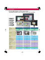
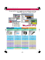
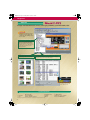
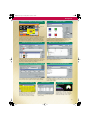
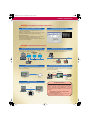
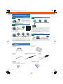
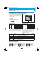
HG_EP1057 Page 1 Thursday, March 16, 2006 1:45 PM
HG2F/HG3F/HG4F
Operator Interface
HG2S
CC Pendant
Design Tool
Super-bright, wide viewing-angle LCD screen
For convenient HMI environment
HG_EP1057 Page 2 Thursday, March 16, 2006 1:45 PM
HG Series Models
Clear legible display in three screen sizes
Teaching Pendant is also available with tactile switches.
HG4F
HG3F
HG2F
HG2S
Large
Model
Medium
12.1 inches
10.4 inches
5.7 inches
HG4F
HG3F
HG2F
TFT
TFT
STN
Pixels
800 × 600
640 × 480
320 × 240
Display Color
256 colors
256 colors
256 colors / Monochrome
User Memory Size
6 MB
6 MB
2 MB
Memory Card (CF)
Yes
Yes
Yes
Ethernet Port
Yes
Yes
—
O/I Link
Yes
Yes
Yes
USB
—
—
Yes
RS232C
Yes
Yes
Yes
RS485/RS422
Yes
Yes
Yes
Screen Size
Type
Appearance
LCD
WindO/I-NV2
Design Tool
See Page
2
10 to 19
10 to 19
10 to 19
HG_EP1057 Page 3 Thursday, March 16, 2006 1:45 PM
HG Series Models
Design tool for easy graphical screen editing by selecting
from 5000 objects in “Symbol Library”
Medium
Small
CC Pendant
Small Teaching Pendant
5.7 inches
4 inches
5.7 inches
4 inches
HG2F w/CC switch
HG1B
HG2S
HG1T
STN
STN
STN
STN
320 × 240
192 × 64
320 × 240
192 × 64
256 colors / Monochrome
Monochrome
256 colors / Monochrome
Monochrome
2 MB
127 KB
2 MB
512 KB
Yes
—
—
—
—
—
—
—
Yes
—
Yes
—
Yes
—
—
—
Yes
Yes
Yes
Yes
Yes
Yes
Yes
Yes
WindE/T
WindO/I-NV2
10 to 19
—
20 to 27
Made upon order
3
HG_EP1057 Page 4 Thursday, March 16, 2006 1:45 PM
Design Tool
Software
Design tool WindO/I-NV2 assists you in programming your HG family O/Is.
Work Area
The project structure can be
listed for easy viewing, and
switched to the editing screen
by one click.
Screen List Project Settings List
Screens can be duplicated and property can be changed easily. Projects
can also be edited effectively. Import
and export functions make it possible
to replace devices, text, and shapes all
at once. Exported CSV files can be
edited using Excel.
Screen Preview List
Screens can be selected from the
preview images and opened quickly.
Object List
Information and figures of devices, condition types, and operation conditions arranged on the screen can be confirmed.
Properties can also be changed using the list
The part selected in the
object list is also reflected
in the editing screen.
System Requirements
• OS
• Computer
• CPU
Windows 95 (OSR2 or later)/98/Me
NT4.0/2000/XP
PC-AT compatible
Pentium 133 MHz or higher
• RAM
• Hard Disk Space
• Graphic
• Others
Windows is a registered trademark of Microsoft Corporation, USA in the USA and other countries.
4
64 MB minimum
50 MB minimum
SVGA (800 × 600) or higher
Mouse, CD-ROM drive
HG_EP1057 Page 5 Thursday, March 16, 2006 1:45 PM
Design Tool
Flexible Screen Display for Efficient Editing
Possible to Reuse Data
Base Screen
Sub Screen
A maximum of 5 base screens can be overlapped, and sub screens
can also be popped up, so screens can be arranged very effectively.
Subscreens can be resized and made transparent to show the
background using the superimpose function as required. In addition, subscreens can be designed to have a move or close button.
Screen data can be imported from another project. Figures and
scripts stored in library can be reused, so accumulated software
properties can be used effectively. Image data of BMP, JPG, DXF,
WMF, and ICO files as well as CAD data can also be used.
Text Browser for Text Data Management
Device Browser for Listing Used Devices
Legends for switches and lamps, and text massages used for the
alarm function can be managed in the text browser. Text property
settings (font, text, color, and size) can be exported to a CSV format
file, which can then be edited on Excel and imported back to the
text browser, resulting in effective screen editing.
Easy Programming of Parts Operating Conditions
Operating conditions for switches and lamps, bit/word write, and
screen switching can be programmed in the property settings for
each part. Lamps can be easily set to turn on, turn off, and flash.
Numeric Key Pad Settings
The standard key pad can be used for easy
inputting of numerals and text. In the popup display mode, the keyboard can be
moved to the best position automatically.
The device browser is used to list devices used in the project and
also to replace used devices at once.
Script Function for Assisting the Host
The HG can process various operations to reduce the task of the
host. On the script editor, conditional equations and functions can
be selected and inputted from the function list. Syntax error check
function is also available.
Alarm Functions
Alarm log data can be listed during operation. Details of each data item can also be
confirmed easily.
Various Graph Functions
Bar graph, trend chart, pie chart, and meter
can be displayed, and their colors, scales,
and labels can be set easily. On the bar
graph, the display color can be changed or
flashed when an input overflow occurs.
5
HG_EP1057 Page 6 Thursday, March 16, 2006 1:45 PM
Features and Functions
Features
The HG series is equipped with most demanded features and functions.
Powerful Functions for Production Data Logging and Management
Alarm Logging and Data Logging
Alarm logging display, alarm list display, and data logging display functions make it easy to view the production information and perform data
collection and management.
Alarm and data logging data can be saved on a CF card in a CSV file format, which can be edited on a PC. In addition, the current screen on
the HG can be printed out or saved in a BMP file format.
Logging Data
Alarm Log Data
PC
CF Card
Monitor and Data Logging through Ethernet
Using the web browser on a PC or PDA, machine operating statuses can be monitored and CF card data can be collected to the
PC through an Ethernet network. Data can be collected from
remote areas.
View Logged Data on a PC
Record Viewer
Using utility software Record Viewer, alarm and log data stored in
the HG can be uploaded through the maintenance communication
and displayed on the PC.
PC or PDA with
web browser
LAN
Ethernet
LAN
HG3F/4F
Host
Speeding Production System Start-up
Debugging Function
Recipe Function
After downloading a created project to the HG, actual operation can
be confirmed while editing the data. Simulation mode makes it possible to debug the project while confirming the HG operation without
the need for connection to the host.
Preset values of the machine (positioning, work piece dimensions,
etc.) can be stored on the internal memory of the HG. Using the
stored preset values (recipe data), the machine can be initialized
easily. The recipe data can be stored on the CF card and edited on
a PC.
(Available on HG models with CF card slot; not available on HG2S)
HG2F/3F/4F
HG2S
PC
Screen Monitor Window
Host
6
..
.
! HG_EP1057 Page 7 Thursday, March 16, 2006 1:45 PM
Features and Functions
.
Multilingual Capabilities for Global Applications
Easy Selection of Multiple Languages
Compatible with Windows Fonts
The text group selection function enables to make a selection from
a maximum of 16 languages by changing the assigned device
value, even during operation.
Windows 2000 and XP makes it possible to input Japanese, Simplified Chinese, Traditional Chinese, and Korean languages.
Fonts used in Windows can be displayed on the HG screens, making it possible to design the attractive screen layout.
Applicable Languages:
Western European languages (English, German, French, Italian,
Spanish, Dutch, Norwegian, Danish, Finnish, Irish, etc.)
Central European languages (Czech, Hungarian, Romanian, Croatian, Slovene, Polish, and Slavic)
Speeding Production System Start-up
Simultaneous Download through O/I Link
Maintenance through Ethernet
In the O/I link communication network, the screen display data can
be downloaded to multiple slaves at once.
The HG models with the Ethernet capability can upload and downloaded the screen display data through the Ethernet.
PC
Ethernet
HG3F/4F
Download from CF Card
PLC Data Exchange through the HG Unit
The screen display data can be downloaded and uploaded using
the CD card without the need of a PC. The CF card can store multiple pieces of project data.
In the network where the HG is connected to an IDEC PLC using
the computer link communication system and the PC is connected
to the HG using the maintenance cable, the PC can exchange data
with the PLC using WindLDR.
HG2F/3F/4F
HG2S
PC
HG2F/3F/4F
CF Card
USB Port on HG2F
The screen display data can be downloaded and uploaded through
the USB port on a computer.
USB
PC
HG2F
WindLDR
WindO/I-NV2
IDEC PLC
MicroSmart
Micro3C
OpenNet Controller
Download Service
Latest versions of WindO/I-NV2, host interface driver,
and user’s manual can be downloaded from the IDEC
web site. Since the system program for the HG can
also be downloaded from WindO/I-NV2, your HG
series devices can be updated to use the latest functionality.
http://www.idec.com/Products/ENG/Software/
SoftwareDownloads.html
After installing WindO/I-NV2, the download page can be
opened from the Windows start menu.
7
HG_EP1057 Page 8 Thursday, March 16, 2006 1:45 PM
Features and Functions
Applicable PLCs
Maker
Series
FA-3S
FA-2J
Micro3
Micro3C
OpenNet Controller
IDEC
MicroSmart
Applicable System (CPU Module)
PF3S-CP12, PF3S-CP13
PF3S-CP11, PF3S-CP11T
PF2J-CPU1
FC2A-C10, FC2A-C16, FC2A-C24
FC2A-C16A, FC2A-C24A
FC3A-CP2
FC4A-C10R2, FC4A-C10R2C
FC4A-C16R2, FC4A-C16R2C,
FC4A-C24R2, FC4A-C24R2C
FC4A-D20K3, FC4A-D20S3,
FC4A-D20RK1, FC4A-D20RS1,
FC4A-D40K3, FC4A-D40S3
A1N, A2N, A3N
A1SH
MELSEC-A
A2CCPUC24
A0J2, A0J2H
A2A, A3A, A2U, A3U, A4U
A2US, A2USH
Mitsubishi
MELSEC-Q
MELSEC-FX
A2N
A1SJH, A1SH, A2SH, A2C, A0J2H
A2A, A3A, A2US, A2USH
A2U
Q02CPU
FX0, FX0N, FX0S, FX1S, FX1, FX2, FX2C
FX2N, FX2NC, FX1N, FX1NC
FX2N
FX1N
C500, C500F, C1000H, C2000, C2000H
C1000HF
C200HS
C200HE, C200HG, C200HX
SYSMAC-C
Sharp
New Satellite JW
Keyence
KV-700
KZ series
C120, C120F
C20H, C28H, C40H, C60H
CQM1H, C200HS-CPU21/23/31/33
C200HE-CPU42, C200HG-CPU43/63,
C200HX-CPU44/64
CPM1, CPM1A, CPM2A
CPM2A
CS1G, CS1H
CS1G, CS1H
PC3J, PC3JD, PC3JG
JW-21CU, JW-22CU, JW-31CUH/H1,
JW-32CUH/H1, JW-33CUH/H1/H2/H3
JW-50CU/CUH, JW-70CU/CUH,
JW-100CU/CUH
JW-22CU, JW-70CU/CUH, JW-100CU/CUH,
JW-32CUH/H1, JW-33CUH/H1/H2/H3
KV-700
KZ-10, KZ-16, KZ-20, KZ-40, KZ-80
Hitachi
S10mini
S10mini
OMRON
CS1 series
Toyoda Machine
TOYOPUC-PC3J
PLC-5
Allen-Bradley
SLC-500
Micro Logix (Full Duplex)
S7-200
Siemens
S7-300
S7-400
Toshiba Machine
GE Fanuc
Automation
Schneider
TC200
Series 90-30
VersaMax
Twido
All PLC-5 models compatible with 1770-KF2
All PLC-5 models
SLC5/03, SLC5/04
Micro Logix 1000, Micro Logix 1200
CPU212, CPU214, CPU215, CPU216, CPU221,
CPU222, CPU224, CPU226, CPU216XM
CPU313, CPU314, CPU315, CPU315-2DP,
CPU316, CPU318
CPU412, CPU414, CPU416, CPU416-F2,
CPU417
TC3-13B1
CPU331, CPU341, CPU350, CPU351, CPU352,
CPU360, CPU363, CPU364, CPU374
CPU311, CPU313, CPU323, CPU331, CPU341,
CPU350, CPU351, CPU352, CPU360, CPU363,
CPU364, CPU374
Nano, Micro (14 points), Micro (23, 28 points)
TWDLCAA16DRF, TWDLCAA24DRF
FP0
FP1
Matsushita
Electric Works
FP series
FPΣ
Yaskawa
Modicon
Koyo
FANUC
8
Machine Controller
MP920, MP930
Momentum
171CCC96020
SU-5E, SU-6B
SU-5E, SU-6B, SU-5M, SU-6M, SU-6H
SZ-4
Power Mate-MODEL D
KOSTAC SU
KOSTAC SZ
Power Mate
Link Unit
PF3S-SIF2, PF3S-SIF4, PF2-CLA
PF2-CLA
Not used (connect to CPU module)
Not used (connect to CPU module)
Not used (connect to CPU module)
Not used (connect to CPU module)
Not used (connect to CPU module)
FC4A-PC1, FC4A-PC3
Not used (connect to CPU module)
FC4A-HPC1, FC4A-HPC3
FC4A-HPH1 + FC4A-PC1
FC4A-HPH1 + FC4A-PC3
AJ71C24, AJ71C24-S3/-S6/-S8,
AJ71UC24
A1SJ71C24-R2, A1SJ71UC24-R2
A1SJ71C24-R4, A1SJ71UC24-R4
Not used (connect to CPU module)
A0J2-C214-S1
AJ71C24-S6/-S8, AJ71UC24
A1SJ71C24-R2, A1SJ71UC24-R2,
A1SJ71C24-R4, A1SJ71UC24-R4
Not used (connect to CPU module)
Not used (connect to CPU module)
Not used (connect to CPU module)
Not used (connect to CPU module)
QJ71C24
Not used (connect to CPU module)
Not used (connect to CPU module)
FX2N-232-BD, FX2N-422-BD
FX1N-232-BD, FX1N-422-BD, FX1N-485-BD
C120-LK201-V1, C120-LK202-V1
C500-LK201-V1, C500-LK203
C500-LK203
C200H-LK201, C200H-LK202
C200H-LK201, C200H-LK202
C200HW-COM02/COM04/COM05/COM06
C200HW-COM03
C120-LK201-V1, C120-LK202-V1
Not used (connect to CPU module)
Not used (connect to CPU module)
Host Interface Driver
FA-3S (CP12/13)
FA-3S (CP11/11T)
FA-2J
Micro3/Micro3C
FC3A/FC4A
MELSEC-AnN (Link)
MELSEC-AnA (Link)
MELSEC-AnN (CPU)
MELSEC-A1S/A2C (CPU)
MELSEC-AnA (CPU)
MELSEC-AnU (CPU)
MELSEC-Q/QnA (Link)
MELSEC-FX (CPU)
MELSEC-FX2N (CPU)
SYSMAC C series
Not used (connect to CPU module)
CPM1-CIF01, CPM1-CIF11
Not used (connect to CPU module)
Not used (connect to CPU module)
CS1W-SCB41 (Port 1) (Port 2)
Not used (connect to CPU module)
SYSMAC CS1 series
TOYOPUC-PC3J
JW-21CM
JW-10CM
JW
Not used (connect to CPU module)
Not used (connect to CPU module)
Not used (connect to CPU module)
Not used (connect to CPU module)
Used
1770-KF2
Not used (connect to CPU module)
Not used (connect to CPU module)
Not used (connect to CPU module)
KV-700
KV/KZ
Not used (connect to CPU module)
S7-200 (PPI)
CP-340, CP-341
CP-440, CP-441
Not used (connect to CPU module)
S10mini
PLC-5
SLC500
Micro Logix 1200
S7-300
3694(R)/RK512
TC200
IC693CMM311
Not used (connect to CPU power module)
Not used (connect to CPU module)
TWDNAC232D, TWDNAC485D, TWDNAC485T
Not used (connect to CPU module)
Not used (connect to RS232C port)
Not used (connect to CPU module)
Not used (connect to CPU module)
Communication cassette AFP801
Communication cassette AFP802
Communication cassette AFP803
Not used (connect to CPU module)
Communication module 217IF
Not used (processor Ethernet port)
Not used (CPU communication port)
U-01DM
Not used (CPU communication port)
Not used (connect to CPU module)
Series 90 (SNP-X)
Modbus RTU
MEWNET
MP920-RTU
MODBUS/TCP
KOSTAC
Power Mate
HG_EP1057 Page 9 Thursday, March 16, 2006 1:45 PM
Features and Functions
Maker
Series
Applicable System (CPU Module)
FA-M3 (F3SP05, F3SP20, F3SP21, F3SP25,
F3SP30, F3SP35, F3SP38, F3SP53, F3SP58,
F3SP36, F3BP20, F3BP30)
FACTORY ACE
Yokogawa
FA-M3 (F3SP05, F3SP21, F3SP25, F3SP28,
F3SP35, F3SP38, F3SP53, F3SP58)
Applicability has been verified on modules shown in bold face in the table above.
The host interface driver can be downloaded from IDEC’s web site: http://www.idec.com/japan/
Link Unit
F3LC11-1N
F3LC11-2N
Host Interface Driver
FA-M3
Not used
HG Available Functions
Category
Communication
Item
PLC link communication
DM link communication
O/I link communication
Ethernet
No host
User Memory
Interface
Display Color
RS232C/RS485 (422)
Ethernet
USB
CF card slot
Parallel
256 colors
Monochrome
Resolution
Touch Switch
CC Switch
Expansion Unit
Features
Functions
Parts
WindO/I-NV2 Functions
Digital I/O unit
LONWORKS communication unit
System program download
Font download
Download via Ethernet
Download via O/I link
Project transfer via CF card
Printer output
External input/output
Backlight replacement
Environment resistance
Simulation
Pass through
Device monitor
Web server function
Overlapped screens
Sub-screen superimpose
Text group switching
Script
Part operating condition setting
Alarm log
Logging
Recipe
Password setting
Bit button
Word button
Goto screen button
Print button
Key button
Keypad
Selector switch
Potentiometer
Numerical input
Character input
Pilot lamp
Picture display
Message display
Message switching display
Alarm list display
Alarm log display
Numerical display
Bar graph
Trend chart
Pie chart
Meter
Calendar
Bit write command
Word write command
Goto screen command
Timer
Print command
Screen print command
Debugging
Log data upload tool
Graphic library tool
Screen import
Text browser
Device browser
Script browser
Picture browser
Basic/advanced mode
Preview
Windows font
Library function
Global replace
Work space
HG2F
Touch Switch Type
CC Switch Type
x
x
x
—
x
2 MB
x
—
x ∗2
x ∗3
—
x
x
320 × 240
16 × 12
—
x
x
x
x
—
x
x ∗3
x ∗4
—
x
x
x
x
x
—
x
x
x
x
x
x
x
x
x
x
x
x
x
x
x
x
x
x
x
x
x
x
x
x
x
x
x
x
x
x
x
x
x
x
x
x
x
x
x
x
x
x
x
x
x
x
x
x
x
x
x
x
x
x
—
x
2 MB
x
—
x ∗2
x ∗3
—
x
x
320 × 240
16 × 8
4 × 1 row (bottom)
x
x
x
x
—
x
x ∗3
x ∗4
—
x
x
x
x
x
—
x
x
x
x
x
x
x
x
x
x
x
x
x
x
x
x
x
x
x
x
x
x
x
x
x
x
x
x
x
x
x
x
x
x
x
x
x
x
x
x
x
x
x
x
x
x
x
x
x
x
x
HG3F
HG4F
x
x
x
x
x
6 MB
x
x ∗1
—
x ∗3
x
x
—
640 × 480
32 × 24
—
x
—
x
x
x ∗1
x
x ∗3
x
—
x
x
x
x
x
— ∗1
x
x
x
x
x
x
x
x
x
x
x
x
x
x
x
x
x
x
x
x
x
x
x
x
x
x
x
x
x
x
x
x
x
x
x
x
x
x
x
x
x
x
x
x
x
x
x
x
x
x
x
x
x
x
x
x
6 MB
x
x ∗1
—
x ∗3
x
x
—
800 × 600
40 × 30
—
x
—
x
x
x ∗1
x
x ∗3
x
—
x
x
x
x
x
— ∗1
x
x
x
x
x
x
x
x
x
x
x
x
x
x
x
x
x
x
x
x
x
x
x
x
x
x
x
x
x
x
x
x
x
x
x
x
x
x
x
x
x
x
x
x
x
x
x
x
x
x
x
HG2S
Touch Switch Type
CC Switch Type
x
x
x (slave only)
—
x
2 MB
x
—
—
—
—
x
x
320 × 240
16 × 12
—
—
—
x
x
—
x
—
x
x
x ∗5
x
x
x
x
—
x
x
x
x
x
x
x
x
x
x
x
x
x
x
x
x
x
x
x
x
x
x
x
x
x
x
x
x
x
x
x
x
x
x
x
x
x
x
x
x
x
x
x
x
x
x
x
x
x
x
x
x
x
x (slave only)
—
x
2 MB
x
—
—
—
—
x
x
320 × 240
10 × 12
6 × 2 columns
—
—
x
x
—
x
—
x
x
x ∗5
x
x
x
x
—
x
x
x
x
x
x
x
x
x
x
x
x
x
x
x
x
x
x
x
x
x
x
x
x
x
x
x
x
x
x
x
x
x
x
x
x
x
x
x
x
x
x
x
x
x
x
x
x
x
x
x
∗1: Available on models with the Ethernet, ∗2: Available on models with the USB interface, ∗3: Available on models with the CF card slot, ∗4: Except for models with the USB interface, ∗5: Replaced at IDEC
9
HG_EP1057 Page 10 Thursday, March 16, 2006 1:45 PM
Operator Interface
Clear, bright display screen
Quick refresh by high-performance CPU
32-bit RISC CPU
256 Colors
350 cd/m2
(HG3F/4F)
250 cd/m2
(HG2F)
HG2F/HG3F/HG4F
10
HG_EP1057 Page 11 Thursday, March 16, 2006 1:45 PM
Operator Interface
HG2F/HG3F/HG4F
Bright, Legible Display
Fast Processing Speed
The HG3F and HG4F feature bright LCD
of 350 cd/m2, and the HG2F has a LCD of
250 cd/m2. Both LCDs ensure a wide
viewing angle and an improved legibility in
bright environments. (The brightness values are presented by the manufacturer.)
The 32-bit RISC CPU on the HG3F and
HG4F have a 200 MHz clock, and the
HG2F has a 133 MHz clock. The
increased speed of screen switching,
parts operation, and communication frees
the operator from the stress of slow operating speed.
CF Card Slot
A compact flash card can be used to store
project data and to copy project data from
one operator interface to the other.
Alarm log, logging
data, and recipe data
can be written to the
CF card, and screen
images can also be
stored in the BMP format.
Ethernet Port (HG3F/HG4F)
Since the HG3F and HG4F is available
with a web server function, a PC or PDA
having a web browser function (Internet
Explorer or Netscape) can be used to
monitor the HG operating status or to
access the files on the CF card.
Operating
statuses
of
machines can also be
monitored easily. Screen
display data can be
uploaded and downloaded
through the Ethernet.
Quick Display Response
Also Available with CC Switches (HG2F)
Tactile feedback from the CC switch assures positive operation and prevents unintended
pressing on the button.
The CC switch has a pushbutton with a LCD indication, and the legend can be changed
according to the program. When pressed, the button clicks to assure positive operation.
CC switches can be used as function switches and other switches which require frequent operation.
Large Memory
Slim Body: 49.6 mm
The HG3F and HG4F have 6MB and the
HG2F has 2MB of user memory to store
screen display data.
(behind the panel HG3F)
USB Port (Option on the HG2F)
The HG2F is available with a USB2.0
OTG (On-The-Go) port having both host
and peripheral functions.
High-speed download of
the screen display data to
the HG is made possible.
The HG4F is 52.1 mm and the HG2F is
50 mm deep behind the panel. The slim
body allows for thin panel design.
High-speed O/I Link
Using optional O/I link unit HG9Z-2G1 on
the HG2F/3F/4F, one PLC can be connected to a maximum of 16 HG units.
PLC
Approvals
Master
11
HG_EP1057 Page 12 Thursday, March 16, 2006 1:45 PM
Operator Interface
Interface Specifications
HG2F
HG2F Operator Interface
Photo shows the HG2F
equipped with a CF
card slot and USB port,
and optional O/I link
unit installed.
Expan- Expansion Interface
sion
Digital I/O Unit
HG9Z-2P101
The optional digital I/O unit installed on the
HG2F provides an expansion of 16 inputs
and 16 outputs.
LONWORKS® Communication Unit
HG9Z-2PNL1
The optional LONWORKS communication
unit installed on the HG2F provides an interface with the LONWORKS network.
Power Terminals
24V DC
CF
Card
Serial Serial Interface 2
USB
RS232C
2
CF Card Interface
O/I
Link
O/I Link Interface
O/I Link Unit (optional)
HG9Z-2G1
CF card 32MB (optional)
HG9Z-MF32
Serial
1
Serial Interface 1
RS232C, RS485 (422)
RS232C and RS485 (422) can
not be used simultaneously.
HG3F / HG4F
HG3F Operator Interface
Expan- Expansion Interface
sion
• Digital I/O Unit Connection
Digital I/O Unit
HG9Z-3P102
The optional digital I/O unit installed
on the HG3F/4F provides an expansion of 16 inputs and 16 outputs.
Power Terminals
24V DC
Parallel
Parallel Interface
Centronics interface standard
For connecting a printer
Ethernet
Serial
2
CF
Card
CF Card Interface
O/I
Link
O/I Link Interface
CF Card 32MB (optional)
HG9Z-MF32
Serial Interface 2
RS232C
Ethernet Interface 10Base-T
Serial
1
O/I Link Unit (optional)
HG9Z-2G1
Serial Interface 1
RS232C, RS485 (422)
RS232C and RS485 (422) can
not be used simultaneously.
Photo shows the HG3F. The HG4F also has almost the same arrangement of interface ports.
The HG3F-FT22VF-B, HG3F-FT22VF-W, HG4F-JT22VF-B, and HG4F-JT22VF-W do not have the Ethernet and CF card interfaces.
LONWORKS is a registered trademark of Echelon, USA.
12
HG_EP1057 Page 13 Thursday, March 16, 2006 1:45 PM
Operator Interface
Communication System
Serial
1
PLC Link Communication
HG2F/3F/4F
O/I
Link
O/I Link Communication
Master
A PLC link unit, programming port on
the CPU module, or another serial
port is used for communication. The
PLC does not require any special
program for PLC link communication.
PLC
RS232C
RS485 (422)
Serial
1
Data can be read from and written
into PLC devices, such as relays and
registers.
HG2F/3F/4F
RS232C
RS485 (422): 2-wire
RS485 (422): 4-wire
Transmission distance: 200m
DM 0
DM 1
DM 2
DM 3
:
DM 8190
DM 8191
1
127
0
0
:
1234
5678
• 1:N Communication
HG2F/3F/4F
HG2F/3F/4F
PLC
One PLC is connected to multiple HG2F/3F/4F units in the O/I link communication system. One O/I serves as a master for a maximum of 15 slaves. The
master communicates with the PLC in the PLC link communication system.
The master can read data from the slaves, and the slaves can write to the
PLC via the master. The master will read data directly from the specified PLC
devices, and the slaves read through the master. The PLC does not require
any special program for communication.
Serial
2
32 max.
Host device such as PC, PLC,
or microcomputer board
15 slaves maximum
PLC Link
Data Memory
Host device such as PC, PLC,
or microcomputer board
HG2F/3F/4F
Slave 2
O/I Link
DM Link Communication
• 1:1 Communication
Slave 1
RS232C (communicate with one HG)
RS485 (422): 2-wire
RS485 (422): 4-wire
Maintenance Communication
HG2F/3F/4F
Software
WindO/I-NV2
PC
Maintenance Cable
The host, such as a PC, PLC, or microcomputer board, can access the DM
link memory in the HG2F/3F/4F to read and write data.
In the 1:1 communication system, one host communicates with one HG unit.
In the 1:N communication system, one host communicates with multiple HG
units. Since special communication protocol for the HG2F/3F/4F is used, the
host requires a special program for DM link communication.
WindO/I-NV2 is used to edit a project on the PC, download and upload the
project to and from the O/I, initialize the O/I, and show the system program
information on the PC.
Options
Maintenance Cable (2m)
HG9Z-XCM22
PLC Connection Cable (5m)
PF3S-KS1
PLC Connection Cable (5m)
HG9Z-3C115
PLC Connection Cable (5m)
HG9Z-3C125
PLC Connection Cable (5m)
HG9Z-3C135
PLC Connection Cable (5m)
HG9Z-3C145
PLC Connection Cable (5m)
HG9Z-3C155
PLC Connection Cable (5m)
HG9Z-3C165
Protective Sheet
CF Card (32 MB)
HG9Z-2D2 (for HG2F) (5 pcs) HG9Z-MF32
HG9Z-3DAPN02 (for HG3F) (2 pcs)
HG9Z-4DAPN02 (for HG4F) (2 pcs)
Digital I/O Unit
HG9Z-2P101 (for HG2F)
HG9Z-3P102 (for HG3F/4F)
16 inputs, 16 outputs
LONWORKS Communication
Unit
HG9Z-2PLN1 (for HG2F)
O/I Link Unit
HG9Z-2G1
WindO/I-NV2
HG9Y-ZSS2W
Replacement Backlight
HG9Z-3FB (for HG3F)
Replacement Backlight
HG9Z-4FB (for HG4F)
Hardware/Software Manual
HG9Y-B596
English/Japanese compatible.
PDF files of user’s manuals are
stored on the CD.
Spare Parts
Replacement Backlight
HG9Z-2B1 (for HG2F)
Mounting Clip (4 pcs)
HG9Z-2K1PN04 (for HG2F)
Mounting Clip (10 pcs)
HG9Z-4K1PN10 (for HG3F/4F)
4 pieces are supplied with HG2F.
4 pieces are supplied with HG3F/4F.
13
HG_EP1057 Page 14 Thursday, March 16, 2006 1:45 PM
HG2F/3F/4F Operator Interfaces
Clear legible display: 350 cd/m2 (HG3F/4F), 250 cd/m2 (HG2F)
Quick screen refresh by high-speed CPU
• 256-color display
• Using the O/I link communication, one host PLC can connect to 16 HG2F/3F/4F units.
• Slim body style — behind-the-panel dimensions are 50 mm
(HG2F), 49.6 mm (HG3F), 52.1 mm (HG4F)
• The HG2F is also available with CC-click switches on the
LCD panel to provide tactile feedback for assurance when
operating the switch.
• In addition to the RS232C/485 (422) serial interface port 1,
the HG2F is available with USB or RS232C serial interface
port 2.
• The HG3F and HG4F are available with or without a CF
(compact flash) card slot and Ethernet port.
• UL, c-UL listed, EN compliant
HG3F (10.4-inch)
HG4F (12.1-inch)
HG2F (5.7-inch) Touch screen type
HG2F (5.7-inch) CC switch type
Types
• HG2F
Display Screen
Operation Type
CF Card Slot
With
With
Without
With
With
Without
With
With
Without
With
With
Without
Touch screen
5.7-inch STN
color LCD
CC switch
Touch screen
5.7-inch STN
monochrome LCD
CC switch
Maintenance Port
(Serial Interface 2)
USB
Communication
(Serial Interface 1)
Housing/
Bezel Color
RS232C
USB
RS232C
USB
RS232C/485 (422)
Light gray
RS232C
USB
RS232C
Type No.
HG2F-SS22VDF
HG2F-SS22VCF
HG2F-SS22VF
HG2F-SS52VDF
HG2F-SS52VCF
HG2F-SS52VF
HG2F-SB22VDF
HG2F-SB22VCF
HG2F-SB22VF
HG2F-SB52VDF
HG2F-SB52VCF
HG2F-SB52VF
The HG2F unit is supplied with four mounting clips HG9Z-2K1.
• HG3F/HG4F
Display Screen
10.4-inch
TFT color LCD
12.1-inch
TFT color LCD
CF Card Slot
Ethernet Port
With
With
Without
Without
With
With
Without
Without
Communication
(Serial Interface 1)
Housing/Bezel Color
Type No.
Dark gray
Light gray
Dark gray
Light gray
Dark gray
Light gray
Dark gray
Light gray
HG3F-FT22TF-B
HG3F-FT22TF-W
HG3F-FT22VF-B
HG3F-FT22VF-W
HG4F-JT22TF-B
HG4F-JT22TF-W
HG4F-JT22VF-B
HG4F-JT22VF-W
RS232C/485 (422)
RS232C/485 (422)
The HG3F or HG4F unit is supplied with four mounting clips HG9Z-4K1.
• Spare Parts
Name
Replacement
Backlight
Mounting Clip
14
Type No.
HG9Z-2B1
HG9Z-3FB
HG9Z-4FB
HG9Z-2K1
HG9Z-4K1
Ordering Type No.
HG9Z-2K1PN04
HG9Z-4K1PN10
Description
For HG2F
For HG3F
For HG4F
For HG2F (4 pieces are supplied with HG2F)
For HG3F/4F (4 pieces are supplied with HG3F/4F)
Package
Quantity
1
1
1
4
10
HG_EP1057 Page 15 Thursday, March 16, 2006 1:45 PM
HG2F/3F/4F Operator Interfaces
• Options
Name
Ordering
Type No.
Type No.
Maintenance Cable HG9Z-XCM22
PF3S-KS1
HG9Z-3C115
HG9Z-3C125
PLC Connection
HG9Z-3C135
Cable
HG9Z-3C145
HG9Z-3C155
HG9Z-3C165
User
Communication
FC2A-KP1C
Cable 1C
HG9Z-2D2
Protective Sheet
HG9Z-3DA HG9Z-3DAPN02
HG9Z-4DA HG9Z-4DAPN02
HG9Z-2P101
Digital I/O Unit
HG9Z-3P102
LONWORKS
Communication
HG9Z-2PNL1
Unit
O/I Link Unit
HG9Z-2G1
CF Card
HG9Z-MF32
Design Tool
HG9Y-ZSS2W
Manual
HG9Y-B596
Description
D-sub 9-pin female connector to connect to computer (2m long) (Note)
For IDEC’s FA-3S SIF2 (5m long)
For IDEC’s Micro3C direct connection (5m long)
For IDEC’s MicroSmart, OpenNet Controller, Micro3C (5m long)
RS232C, D-sub 25-pin, for Mitsubishi/OMRON link unit (5m long)
RS232C, D-sub 9-pin, for Mitsubishi link unit (5m long)
RS232C, D-sub 9-pin, for OMRON RS232C interface (5m long)
For Mitsubishi FX/A series direct connection (5m long)
Package
Quantity
1
1
1
1
1
1
1
1
For connecting the HG2F serial interface 2 port (RS232C) to a serial
printer; not equipped with a connector for connecting the printer
1
For HG2F (5 pack)
For HG3F (2 pack)
For HG4F (2 pack)
For HG2F, 16 inputs / 16 outputs
For HG3F/4F, 16 inputs / 16 outputs
5
2
2
1
1
For HG2F
1
Communication unit for O/I link
Compact flash memory card, 32 MB
WindO/I-NV2 on CD (English/Japanese compatible) w/o printed manual
PDF files of English/Japanese manuals are stored on the CD.
English hardware/software manual
1
1
1
1
Note: Computer link cable 4C (FC2A-KC4C) for IDEC’s MicroSmart, OpenNet Controller, and Micro3C is also applicable.
General Specifications
Type
Rated Power Voltage
Power Voltage Range
Power Consumption
Power Inrush Current
Allowable Momentary Power Interruption
Dielectric Strength
Insulation Resistance
Operating Temperature
Operating Humidity
Storage Temperature
Storage Humidity
Pollution Degree
Corrosion Immunity
Vibration Resistance (damage limits)
Shock Resistance (damage limits)
Noise Immunity
Electrostatic Discharge
Mounting
Degree of Protection
Dimensions (mm)
Weight (approx.)
HG2F
HG3F
HG4F
24V DC
20.4 to 28.8V DC
19.2 to 28.8V DC
10W maximum
25W maximum
20A maximum
15A maximum (cold start)
10 ms minimum
1,000V AC, 10 mA, 1 minute
1,500V AC, 10 mA, 1 minute between power and FG terminals
between power and FG terminals
50 MΩ minimum between power and
10 MΩ minimum between power and FG terminals (500V DC megger)
FG terminals (500V DC megger)
0 to 50°C (no freezing)
0 to 45°C (no freezing)
10 to 95% RH (no condensation)
20 to 85% RH (no condensation)
–20 to +60°C (no freezing)
10 to 95% RH (no condensation)
20 to 85% RH (no condensation)
2 (IEC 60664-1)
Atmosphere free from corrosive gases
10 to 20 Hz amplitude 0.625 mm, 20 to 55 Hz acceleration 9.8 m/s2
2 hours per axis on each of three mutually perpendicular axes
147 m/s2, 11 ms, 5 shocks on each of three mutually perpendicular axes
Fast transient/burst test, common mode: Level 3, power terminals: ±2 kV, communication line: ±1 kV
(IEC/EN 61000-4-4)
ESD-3 (RH-1), Level 3, (contact ±6 kV, aerial ±8 kV) (IEC/EN 61000-4-2)
Panel mounting
IP65 NEMA TYPE 13 (operator)
IP66 NEMA TYPE 4.4X (operator)
172W × 136H × 56D
324W × 240H × 55.8D
348W × 270H × 58.1D
800g
2800g
3400g
Operation Specifications
Type
Switching Element
Resolution
CC Switch Quantity
Operating Force
Mechanical Life
Acknowledge Sound
Multiple Operations
HG2F
HG3F
HG4F
Touch Screen Type
CC Switch Type
Resistive membrane
16 × 12
16 × 8
32 × 24
40 × 30
4 × 1 row
—
—
—
(bottom only)
0.2 to 0.8N
2.5 to 5.0N
0.2 to 0.8N
0.2 to 0.8N
1,000,000 operations
Electronic buzzer
Possible to press two switching areas simultaneously (CC switch and touch screen cannot be pressed together)
15
HG_EP1057 Page 16 Thursday, March 16, 2006 1:45 PM
HG2F/3F/4F Operator Interfaces
Display Specifications
Type
LCD
Effective Display Area (mm)
Display Resolution
LCD Life
Contrast Adjustment
Backlight
Backlight Life
Backlight Control
Backlight Replacement
1/4 size
Display Character Size
Quantity of Characters
(CC Switch Type)
Character Magnification
Character Attribute
Graphics Type
Window Display
1/2 size
Full size
Double size
1/4 size
1/2 size
Full size
Double size
HG2F
HG3F
HG4F
Color
Monochrome
Color
Color
Color STN
Monochrome STN
Color TFT
118.2W × 89.4H
211.2W × 158.4H
246W × 184.5H
320W × 240H pixels
640W × 480H pixels
800W × 600H pixels
50,000 hours minimum
100,000 hours minimum
60,000 hours minimum
Possible in steps using the front touch screen
Cold-cathode tube
Cold-cathode tube (2 tubes)
40,000 hours nominal (Note)
50,000 hours nominal (Note)
Automatic OFF
Possible
8 × 8 pixels (Western European language: ISO 8859-1, Central European language: ANSI 1250,
Japanese katakana and symbols: JIS 8-bit code)
8 × 16 pixels (Western European language ISO 8859-1, Central European language: ANSI 1250,
Japanese katakana and symbols: JIS 8-bit code)
16 × 32 pixels, 24 × 48 pixels, 32 × 64 pixels (Western European language: ISO 8859-1)
16 × 16 pixels (Japanese JIS first and second level characters, simplified Chinese, traditional Chinese, Korean)
32 × 32 pixels (Japanese JIS first level characters, Mincho font)
40 characters × 30 lines (40 × 20)
80 characters × 60 lines
100 characters × 75 lines
40 characters × 15 lines (40 × 10)
80 characters × 30 lines
100 characters × 37 lines
20 characters × 15 lines (20 × 10)
40 characters × 30 lines
50 characters × 37 lines
10 characters × 7 lines (10 × 5)
20 characters × 15 lines
25 characters × 18 lines
0.5, 1, 2, 3, 4, and 8 vertically and horizontally
Blink (1 or 0.5 sec period), reverse, bold, shadowed
Straight line, polyline, polygon, rectangle, circle, ellipse, arc, pie, equilateral polygons (3, 4, 5, 6, 8), paint, bitmap image
3 popup screens + 1 system screen
Note: The backlight life refers to the time until the surface brightness reduces to a half after using continuously at room temperatures.
Power Failure
Backup
CF Card Interface Specifications
Interface Specifications
Connector
Compact Flash Type I standard compliant
50-pin compact flash card connector
Parallel Interface Specifications (HG3F/4F)
Electrical Characteristics
Connector
Centronics interface compliant
D-sub 25-pin female connector
Ethernet Specifications (HG3F/4F)
Interface Specifications
IEEE 802.3 standard compliant, 10Base-T
USB Interface Specifications (HG2F)
Interface Specifications
Connector
USB 2.0 compliant
Mini AB connector
For connecting with a PC using a USB port, use a USB cable with a 5-in USB
mini B male connector on the HG side.
16
RS232C
RS485 (422)
Transmission Speed
Synchronization
Communication Method
Control System
Connector
Electrical
Characteristics
Transmission Speed
Synchronization
Communication Method
Control System
Connector
Applicable Quantity
Mounting Style
Input Points
Rated Voltage
Isolation Method
Output Points
Load Voltage
Isolation Method
Output Signal
Output ON Voltage
Output Current
Input
Print Function
(support)
Electrical
Characteristics
Output
Calendar
Interface Specifications
Expansion Unit (Digital I/O Unit)
Parts
HG2F
HG3F/4F
Base screen, popup screen, system screen
Base screen: 3000 max., popup screen: 3015 max.
2 MB
6 MB
Bit Button, Word Button, Goto Screen Button, Print Button, Key Button, Keypad, Selector Switch, Potentiometer, Numerical Input, Character Input, Pilot Lamp,
Picture Display, Message Display, Message Switching
Display, Alarm List Display, Alarm Log Display, Numerical Display, Bar Graph, Trend Chart, Pie Chart, Meter,
Calendar, Bit Write Command, Word Write Command,
Goto Screen Command, Timer, Print Command,
Screen print
Year, Month, Day, Hour, Min., Sec., Day of Week
±30 sec per month (at 25°C)
SII printer,
ESC/P, PC-PR, PCL command;
DPU-414
EPSON PX-V600/Stylus C84
Backup data: Calendar, log data, keep internal relay,
keep internal register
Backup duration: 1 month (at 25°C) after full charging
for two days
Connector
Maintenance
Communication
Type
Screen Types
No. of Screens
User Memory
O/I Link
Communication
Operation Specifications
Electrical
Characteristics
Transmission Speed
Synchronization
Communication
Method
Connector
Electrical
Characteristics
Transmission Speed
Synchronization
Communication
Method
Connector
EIA RS232C compliant
1200, 2400, 4800, 9600, 19200, 38400,
57600, 115200 bps
Asynchronous
Half or full duplex
Hardware control or none
D-sub 25-pin female connector
EIA RS485 (422) compliant
1200, 2400, 4800, 9600, 19200, 38400,
57600, 115200 bps
Asynchronous
Half or full duplex
Hardware control or none
D-sub 25-pin female connector
1
Mounted on the rear of the HG unit
16
12 to 24V DC (allowable range 10 to 28V DC)
Photocoupler
16
12 to 24V DC (allowable range 10 to 28V DC)
Photocoupler
NPN open collector
1.6V maximum
30 mA max. per point, 200 mA total
24-pin connector (Fujitsu FCN-365P024-AG)
2 connectors for inputs and outputs
EIA RS232C compliant
9600, 19200, 38400, 57600, 115200 bps
Asynchronous
Half duplex, proprietary protocol
Mini DIN 8-pin connector
EIA RS485 compliant
38400, 57600, 115200 bps
Asynchronous
Half duplex, proprietary protocol
Special connector
HG_EP1057 Page 17 Thursday, March 16, 2006 1:45 PM
HG2F/3F/4F Operator Interfaces
Dimensions
When installing the HG on a panel, keep a sufficient space to connect and disconnect cables and to install and remove the CF
card as required.
• HG2F
Mounting Clips (4 places)
Screw Tightening Torque:
0.15 to 0.2 N·m
CC-Switch Type Front View
Panel Thickness:
1.6 to 5
108.2
172
172
6
Expansion Unit
Screw Tightening Torque:
0.3 to 0.5 N·m
3.2
136
136
100
126
3.2
Touch Switch Type Front View
Power Terminal
O/I Link Unit
Serial Interface 1
(Host Interface)
Serial Interface 2
(Maintenance Interface)
82
56
CF Card Interface
Expansion Unit
138
162
5.2
• HG3F
Expansion Interface (optional)
221
Mounting Clips (4 places)
Screw Tightening Torque (0.6 N·m)
2.7
Panel Thickness 2 to 5
240
O/I Link Interface (optional)
CF Card
Interface
6.2
Serial Interface 2
(Maintenance Interface)
324
55.8
Ethernet Interface
Serial Ineterface 1
(Host Interface)
Power Terminal (M4 screw)
Parallel Interface
(Printer Interface)
All dimensions in mm.
17
HG_EP1057 Page 18 Thursday, March 16, 2006 1:45 PM
HG2F/3F/4F Operator Interfaces
• HG4F
Expansion Interface (optional)
Mounting Clip (4 places)
Screw Tightening Torque: 0.6 N·m
240
2.7
Panel Thickness 2 to 5
270
O/I Link Interface (optional)
CF Card
Interface
6
Serial Interface 2
(Maintenance Interface)
348
58.1
Ethernet Interface
Parallel Interface
(Printer Interface)
Serial Ineterface 1
(Host Interface)
Power Terminal (M4 screw)
Panel Cutout
• HG3F
Panel thickness: 1.6 to 5 mm
Panel thickness: 2 to 5 mm
+1
+0.5
+0.5
332 0
302 0
162 0
228 +0.5
0
126.5 +0.5
0
• HG4F
Panel thickness: 2 to 5 mm
258 +1
0
• HG2F
All dimensions in mm.
Safety Precautions
• Turn off the power to the HG unit before starting installation, removal, wiring, maintenance, and inspection of the
HG unit. Failure to turn power off may cause electrical
shock or fire hazard.
skin. If the LCD is broken and the liquid attaches to your
skin or clothes, wash the liquid off using soap, and consult
a doctor immediately.
• Special expertise is required to install, wire, configure, and
operate the HG unit. People without such expertise must
not use the HG unit.
• Emergency and interlocking circuits must be configured
outside the HG unit. If such a circuit is configured inside
the HG unit, failure of the HG unit may cause a serious
damage to the external devices.
• The HG unit uses an LCD (liquid crystal display) as a display device. The liquid inside the LCD is harmful to the
• Read the following operating instructions to make sure of
safety.
18
HG_EP1057 Page 19 Thursday, March 16, 2006 1:45 PM
HG2F/3F/4F Operator Interfaces
Operating Instructions
3. Noise
When installing and wiring the HG unit or when designing
control panel including connection to the host device,
observe the following instructions to make sure of safety of
the personnel and performance of the HG unit.
• Do not install the HG unit near high-voltage devices or arcgenerating equipment, such as electromagnetic contactors and no-fuse breakers.
1. Installation Location
• Keep a minimum of 200 mm from motor lines.
In consideration of the safety and HG performance, avoid
installing the HG unit in the following locations:
• Make the power connection to the HG unit as short as
possible.
• Where dust, briny air, or iron particles exist in quantity
• Where oil or chemical splashes exist
• Where direct sunlight falls on the HG unit
• Where a corrosive gas or flammable gas exists
• Where the HG unit is subjected to vibrations or shocks
• Where dew condensation occurs due to rapid temperature
change
• Separate the connection lines for motor devices from
power lines for I/O devices connected to the HG unit.
2. Ambient Temperature
• Keep a minimum of 100 mm clearance around the HG unit
for ventilation. Do not install the HG unit near heat-generating machines.
• When the ambient temperature exceeds the rated operating temperature of the HG unit, install a ventilating fan or
air-conditioner.
• The HG unit is designed for installation on a vertical plane
and natural air cooling. When installing the HG unit in
other directions, provide forced air cooling or reduce the
ambient temperature.
• For connection with host devices, various cables are available for each HG unit. Select a correct cable for the HG
unit and host device.
• When making a cable for connecting the HG unit to a host,
use the recommended connector and applicable wire.
When the maximum cable length is defined, observe the
maximum cable length.
4. Operability and Maintenance
• In consideration of the viewing angle and switch operation,
install the HG unit at a convenient height.
• The touch screen surface and CC switch lens are easily
damaged. Do not scratch or press strongly on the surfaces
using hard tools.
• To wipe off smears on the lens and screen surface, use a
soft cloth dampened with the following solvents.
Neutral detergent (squeeze the cloth tightly)
Alcoholic solvents
Do not use solvents such as thinner, ammonia, strong
acid, and strong alkaline.
19
HG_EP1057 Page 20 Thursday, March 16, 2006 1:45 PM
CC Pendant
HG2S is a mobile teaching pendant consisting of mechanical switches (SUI),
touch switches (GUI), and CC switches on the screen (SUI on GUI)
IDEC’s Original Safety Features
Safety Lock Mechanism
Contacts open only after the operator is locked.
Direct Opening Action
Mechanical Switch
Stop Switch (Gray Button)
Emergency Stop Switch (Red Button)
Contacts, when welded, are forced to open directly.
Emergency stop switch has a legend “EMERGENCY STOP.”
▲ With mechanical switches
▼ Without mechanical switches
Touch Switch
(12 rows × 10 columns)
Safety c
CC Switch
(6 rows × 2 columns)
Enabling Switch
GUI
SUI
Graphical User Interface
Solid User Interface
• A type of HMI which shows graphic
objects on the display screen to operate virtual control units.
• Typical examples include a LCD
screen with touch switches to operate
the switches on the screen.
Enabling Switch Operation
OFF
• A type of HMI which operates mechanical control units such as pushbuttons.
• Typical examples include LED indicators as well as mechanical switches.
Press lightly
(CC Switch)
• A new type of control display unit
which consists of mechanical switch
operators arranged on the LCD screen
in consideration of ergonomics.
• The tactile feedback of the switch
operator, when pressed, assures the
operation of the switch.
Release
Direct
opening
OFF
Safety SUI
• Among the SUI, such as pushbutton switches, intended to create the
optimum environment for human
and machinery, those directly related to safety are called Safety SUI.
• Typical examples include safety
switches, emergency stop pushbuttons, stop switches, and enabling
switches.
HG2S CC Pendant Rear View
20
HG2
Release
ON
Press further
SUI on GUI
Mee
Installed on the back of the CC pendant is a
3-position enabling switch, which has been
developed to enhance the safety for human
and machinery based on ergonomics.
ANSI/RIA R15.06-1999 American National
Standard for Industrial Robots and Robot
Systems defines “4.7.3 Enabling device: The
pendant or teaching device shall have an
enabling device using a three position switch
which, when continuously held in a detented
position, permits motion.”
HG_EP1057 Page 21 Thursday, March 16, 2006 1:45 PM
CC Pendant
al switches (SUI),
on GUI)
ty Features
Brightness 250 cd/m 2, 256 colors ensure clear display
chanism
ter the operator is locked.
Brightness according to manufacturer.
Action
8-color Display
d, are forced to open directly.
256-color Display
end “EMERGENCY STOP.”
High-speed CPU for fast processing and communication
The 32-bit RISC CPU/133MHz ensures fast switching of screens, fast processing of parts, and fast communication.
Safety concepts packed in the mobile control panel
CC Switch
(6 rows × 2 columns)
Meets global standards
Applicable Standards
Switch Operation
OFF
Applicable
Standards for
Use
World
IEC60950, IEC60204-1
ISO10218
IEC61000-6-4 (EMC)
IEC61131-2 (EMC)
North
America
UL508
CSA C22.2 No.14
FCC Part15 (EMC)
ANSI RIA15.06
UL1740
Europe
EN60950, EN60204-1
EN61000-6-4 (EMC)
EN61131-2 (EMC)
EN775
Japan
JIS C 6950
JIS B 9960-1
JIS B 8433
ISO20218 and IEC60204-1 require that a pendant shall
have an emergency stop switch. Now it is under deliberation that a stop switch can also be used instead of an
emergency stop switch depending on the application of
the pendant.
IDEC’s proven safety concepts
The HG2S CC pendant features a 3-position enabling switch that
is required by the safety standards, and also a stop switch or
emergency stop switch. All these switches are field-proven IDEC’s
control switches.
The HG2S is available with a stop switch (gray button) or an
emergency stop switch (red button), which can be selected
according to the risk assessment and assists in the inherently safe
design of machinery based on ISO12100.
• When the CC pendant can be easily disconnected from the machine control
circuit, a stop switch shall be used to indicate that the gray button does not
function as an emergency stop switch when the CC pendant is disconnected
from the machine.
• When the CC pendant is integrated with the machine control circuit, an
emergency stop switch with a red button can be used since the emergency stop
switch is always connected to the machine control circuit and the emergency
stop function is always enabled.
HG2S Configuration Examples
Release
ON
• The HG2S can mount ø16mm L6 series control switches,
such as pushbuttons, illuminated pushbuttons, selector
switches, and key selector switches.
Release
Direct
opening
OFF
ack of the CC pendant is a
g switch, which has been
ance the safety for human
ased on ergonomics.
-1999 American National
strial Robots and Robot
“4.7.3 Enabling device: The
ng device shall have an
sing a three position switch
nuously held in a detented
motion.”
Square control units are also available with switch guards.
21
HG_EP1057 Page 22 Thursday, March 16, 2006 1:45 PM
CC Pendant
Communication System
Serial
1
PLC Link Communication
HG2S
PLC
RS232C
RS485 (422)
Data can be read from and written
into PLC devices, such as relays and
registers.
O/I
Link
O/I Link Communication
Master
(HG2F/3F/4F)
A PLC link unit, programming port on
the CPU module, or another serial
port is used for communication. The
PLC does not require any special
program for PLC link communication.
Slave 1
Slave 2
O/I Link
Transmission distance: 200m
Serial
1
DM Link Communication
15 slaves maximum
PLC Link
PLC
• 1:1 Communication
Data Memory
HG2S
DM 0
DM 1
DM 2
DM 3
:
DM 8190
DM 8191
RS232C
RS485 (422): 2-wire
RS485 (422): 4-wire
1
127
0
0
:
1234
5678
Host device such as PC, PLC,
or microcomputer board
The master can read data from the slaves, and the slaves can write to the
PLC via the master. The master will read data directly from the specified PLC
devices, and the slaves read through the master. The PLC does not require
any special program for communication.
• 1:N Communication
HG2S
HG2S
One PLC is connected to multiple HG2F/3F/4F/2S units in the O/I link communication system. HG2S units with RS485 port are used for O/I link communication. One O/I serves as a master for a maximum of 15 slaves. The master
communicates with the PLC in the PLC link communication system.
HG2S
Serial
2
Maintenance Communication
HG2S
32 max.
Host device such as PC, PLC,
or microcomputer board
RS232C (communicate with one HG)
RS485 (422): 2-wire
RS485 (422): 4-wire
Software
WindO/I-NV2
PC
Maintenance Cable
The host, such as a PC, PLC, or microcomputer board can access the DM
link memory in the HG2S to read and write data.
In the 1:1 communication system, one host communicates with one HG unit.
In the 1:N communication system, one host communicates with multiple HG
units. Since special communication protocol for the HG2S is used, the host
requires a special program for DM link communication.
WindO/I-NV2 is used to edit a project on the PC, download and upload the
project to and from the O/I, initialize the O/I, and show the system program
information on the PC.
Options
Maintenance Cable (2m)
HG9Z-XCM22
Wrist Strap
HG9Z-PS1
Protective Sheet
HG9Z-PE1
Hand Strap (supplied with the HG2S)
HG9Z-PS2
WindO/I-NV2
HG9Y-ZSS2W
English/Japanese compatible.
PDF files of user’s manuals are stored on the CD.
22
Neck Strap
HG9Z-PS3
Hardware/Software Manual
HG9Y-B596
HG_EP1057 Page 23 Thursday, March 16, 2006 1:45 PM
HG2S CC Pendant
Mobile teaching pendant designed with safety concepts
3-position enabling switch is a standard provision on the back.
• 256-color 5.7-inch LCD screen for touch switch and display
• CC switches and mechanical switches combined with touch
switches on the LCD screen make up ideal HMI equipment.
• High-performance CPU ensures stress-free quick response.
• The grip is made of elastomer to prevent the CC pendant
from slipping out of hand.
• IP65 water- and dust-proof structure
• The screen display and operation can be easily designed
using WindO/I-NV2.
• UL (UL508), c-UL (CSA C22.2 No. 14) listed,
IEC/EN 60950, IEC/EN 60204-1 compliant
• EMC (IEC/EN 61000-6-4, IEC/EN 61131-2) compliant
Types
• Without Mechanical Switch
CC Switch
With
CC Switch
Without
CC Switch
LCD
Color
Monochrome
Color
Monochrome
Host I/F
RS232C
RS485/422
RS232C
RS485/422
RS232C
RS485/422
RS232C
RS485/422
• With Mechanical Switch
Type No.
HG2S-SS62BH-A3➁
HG2S-SS62YH-A3➁
HG2S-SB62BH-A3➁
HG2S-SB62YH-A3➁
HG2S-SS32BH-A3➁
HG2S-SS32YH-A3➁
HG2S-SB32BH-A3➁
HG2S-SB32YH-A3➁
• Above type numbers are for a 3m cable. When a 5m or 10m cable
is required, replace “3” at the end with “5” or “10” respectively.
• In place of ➁, specify a code for stop switch (gray button) or emergency stop switch (red button): N (gray), Blank (red)
• Each HG2S unit is supplied with one HG9Z-PS2 hand strap and
one HG9Z-PK2 mounting bracket.
LCD
CC Switch
With
CC Switch
Without
CC Switch
Color
Monochrome
Color
Monochrome
Host I/F
RS232C
RS485/422
RS232C
RS485/422
RS232C
RS485/422
RS232C
RS485/422
Type No.
HG2S-SS62BH-S➀-➁➂
HG2S-SS62YH-S➀-➁➂
HG2S-SB62BH-S➀-➁➂
HG2S-SB62YH-S➀-➁➂
HG2S-SS32BH-S➀-➁➂
HG2S-SS32YH-S➀-➁➂
HG2S-SB32BH-S➀-➁➂
HG2S-SB32YH-S➀-➁➂
• In place of ➀, specify a cable length code: 3 (3m), 5 (5m), 10
(10m)
• In place of ➁, specify a code for stop switch (gray button) or emergency stop switch (red button): N (gray), R (red)
• In place of ➂, a file number controlled by IDEC enters to specify
mechanical switches and their layout. For specifying mechanical
switches, use the HG2S specification sheet on page???.
• Each HG2S unit is supplied with one HG9Z-PS2 hand strap and
one HG9Z-PK2 mounting bracket.
• Options
Name
Maintenance Cable
User Communication Cable
Protective Sheet
Wrist Strap
Hand Strap
Neck Strap
Mounting Bracket
Type No.
HG9Z-XCM22
Design Tool
HG9Y-ZSS2W
Manual
HG9Y-B596
FC2A-KP1C
HG9Z-PE1
HG9Z-PS1
HG9Z-PS2
HG9Z-PS3
HG9Z-PK2
Description
D-sub 9-pin female connector to connect to computer (2m long) (Note)
For connecting the HG2S serial interface 2 port (RS232C) to a serial printer;
not equipped with a connector for connecting the printer
Dustproof protective sheet for CC switches
Supplied with the HG2S
Supplied with the HG2S
WindO/I-NV2 on CD (English/Japanese compatible) w/o printed manual
PDF files of English/Japanese manuals are stored on the CD.
English hardware/software manual
Package Quantity
1
1
1
1
1
1
1
1
1
Note: Computer link cable 4C (FC2A-KC4C) for IDEC’s MicroSmart, OpenNet Controller and Micro3C is also applicable.
HG2S Configuration Examples
Various ø16mm L6 series control units can be mounted, such as pushbuttons, illuminated pushbuttons, selector switches, and key selector switches.
Example 1
Example 2
Example 3
CC Switches
6 × 2 columns (right/left)
CC Switches
6 × 2 columns (right/left)
CC Switches
6 × 2 columns (right/left)
Mechanical Switches
E-stop switch: 1
Round pushbutton: 2
Enabling switch: 1
Mechanical Switches
E-stop switch: 1
Round pushbutton: 2
Square pushbutton: 5
Key switch: 1
Enabling switch: 1
Mechanical Switches
E-stop switch: 1
Round pushbutton: 2
Illuminated pushbutton: 6
Enabling switch: 1
23
HG_EP1057 Page 24 Thursday, March 16, 2006 1:45 PM
HG2S CC Pendant
General Specifications
Display Specifications
24V DC
21.6 to 26.4V DC
10W maximum
30A maximum
10 ms minimum
500V AC, 10 mA, 1 minute between power and FG
terminals
10 MΩ minimum between power and FG terminals
(500V DC megger)
0 to 40°C (no freezing)
20 to 85% RH (no condensation)
–20 to +60°C (no freezing)
20 to 85% RH (no condensation)
10 to 55 Hz acceleration 9.8 m/s2
2 hours per axis on each of three mutually perpendicular axes
98 m/s2, 11 ms, 5 shocks on each of three mutually
perpendicular axes
Fast transient/burst test, common mode: Level 3,
power terminals: ±2 kV, communication line: ±1 kV
(IEC/EN 61000-4-4)
ESD-3 (RH-1), Level 3, (contact ±6 kV, aerial ±8 kV)
(IEC/EN 61000-4-2)
Atmosphere free from corrosive gasses
Hand-held or hang on hook with mounting bracket
IP65 (CC switch: IP20, except connector)
3m (standard), 10m maximum
228W × 186H × 57D
1200g (except cable)
Vibration Resistance
(damage limits)
Shock Resistance
(damage limits)
Noise Immunity
Electrostatic
Discharge
Corrosion Immunity
Mounting
Degree of Protection
Cable Length
Dimensions (mm)
Weight (approx.)
Resolution
Operating Force
Mechanical Life
Acknowledge Sound
Multiple Operations
➀ Stop/E-stop Switch
➁ Enabling Switch
➂ Round Switch
➃ Square Switch
Full size
Double size
1/4 size
1/2 size
(Touch
screen on CC Full size
Switch Type) Double size
Character Magnification
Quantity of
Characters
Character Attribute
Graphics Type
Window Display
Touch Screen
CC Switch
Resistive membrane
Resistive membrane
16 × 12
6 × 2 columns (right/left)
(CC switch type: 10 × 12)
0.2 to 0.8N
2.5 to 5N
1,000,000 operations
Electronic buzzer
Possible to press two switching areas simultaneously
HA1E type, 1 switch, 2NC contacts,
Contact rating 24V DC, 1A
HE1B type, 2 switches, OFF-ON-OFF contact,
Contact rating 24V DC, 50 mA
L6 series round pushbuttons, 4 switches maximum
1NO or 2NO contacts,
Contact rating 24V DC, 50 mA
L6 series square pushbuttons or illuminated pushbuttons, 6 switches maximum
1NO or 2NO contacts,
Contact rating 24V DC, 50 mA
Interface Specifications
Electrical Characteristics
24
➃
➂
➁
Synchronization
Communication Method
Control System
Connector
Electrical Characteristics
Transmission Speed
Synchronization
Communication Method
Control System
Connector
Input Points
Rated Voltage
Isolation Method
Input
Resistance/Current
Input Signal Level
Output Points
Load Voltage
Isolation Method
Output Signal
Output ON Voltage
Output Current
Connector
Electrical
Characteristics
Transmission Speed
Synchronization
Comm. Method
Connector
Electrical
Characteristics
Transmission Speed
Synchronization
Comm. Method
Connector
Maintenance
Communication
➀
Transmission Speed
EIA RS232C compliant
1200, 2400, 4800, 9600, 19200, 38400,
57600, 115200 bps
Asynchronous
Half or full duplex
Hardware control or none
D-sub 37-pin connector (JAE’s DC-37-PF-N)
EIA RS485 (422) compliant
1200, 2400, 4800, 9600, 19200, 38400,
57600, 115200 bps
Asynchronous
Half or full duplex
Hardware control or none
D-sub 37-pin connector (JAE’s DC-37-PF-N)
4
12 to 24V DC (allowable range 10 to 28V DC)
Photocoupler
Approx. 3.9 kΩ / approx. 6 mA
(input voltage 24V DC)
ON voltage: 8V min., OFF voltage: 4V max.
3 (including 1 point for RUN output)
12 to 24V DC (allowable range 10 to 28V DC)
Photocoupler
NPN open collector
1.6V maximum
50 mA max. per point, 200 mA total
D-sub 37-pin connector (JAE’s DC-37-PF-N)
EIA RS232C compliant
O/I Link
Communication
➃
External I/O
Mechanical Switch Layout
➂
1/2 size
Color
Monochrome
5.7” color STN
5.7” monochrome STN
256 colors
2 colors
118.2W × 89.4H mm
320W × 240H pixels
Possible using the front touch screen
Cold-cathode tube (Note)
40,000 hours nominal
Automatic OFF
Replaceable at IDEC factory
8 × 8 pixels
JIS 8-bit code
ISO 8859-1 (west European)
8 × 16 pixels
ANSI 1251 (central European)
16 × 32 pixels
24 × 48 pixels ISO 8859-1 (west European)
32 × 64 pixels
JIS 1st/2nd level, Simplified
16 × 16 pixels Chinese, Traditional Chinese,
Korean
32 × 32 pixels JIS first level characters
40 characters × 30 lines (27 × 30)
40 characters × 15 lines (27 × 15)
20 characters × 15 lines (13 × 15)
10 characters × 7 lines (6 × 7)
0.5, 1, 2, 3, 4, and 8 vertically and horizontally
Blink (1 or 0.5 sec period), reverse, bold,
shadowed
Straight line, polyline, polygon, rectangle, circle,
ellipse, arc, pie, equilateral polygons (3, 4, 5, 6,
8), paint, bitmap image
3 popup screens + 1 system screen
Note: The time until the surface brightness reduces to a half.
Operation Specifications
Switch Type
Switching Element
Display
Character
Size
RS232C
Operating
Temperature
Operating Humidity
Storage Temperature
Storage Humidity
RS485 (422)
Insulation Resistance
Input
Dielectric Strength
Type
LCD
Display Color
Effective Display Area
Display Resolution
Contrast Adjustment
Backlight
Backlight Life
Backlight Control
Backlight Replacement
1/4 size
Output
Rated Power Voltage
Power Voltage Range
Power Consumption
Power Inrush Current
Allowable Momentary
Power Interruption
EIA RS485 compliant
9600, 19200, 38400, 57600, 115200 bps
Asynchronous
Half duplex, proprietary protocol
Mini DIN 8-pin connector
38400, 57600, 115200 bps
Asynchronous
Half duplex, proprietary protocol
D-sub 37-pin connector (JAE’s DC-37-PF-N)
HG_EP1057 Page 25 Thursday, March 16, 2006 1:45 PM
HG2S CC Pendant
Operation Specifications
Screen Types
No. of Screens
User Memory
Parts
Calendar
Print Function (support)
Power Failure Backup
Base screen, popup screen, system screen
Base screen: 3000 max., popup screen: 3015 max.
2 MB
Bit Button, Word Button, Goto Screen Button, Key Button, Print Button, Keypad, Selector Switch, Potentiometer, Numerical Input,
Character Input, Pilot Lamp, Picture Display, Message Display, Message Switching Display, Alarm List Display, Alarm Log Display,
Numerical Display, Bar Graph, Trend Chart, Pie Chart, Meter, Calendar, Bit Write Command, Word Write Command, Goto Screen
Command, Timer, Print Command, Screen Print
Year, Month, Day, Hour, Min., Sec., Day of Week
±30 sec per month (at 25°C)
SII printer, DPH-414
Backup data: Calendar, log data, keep internal relay, keep internal register
Backup duration: 1 month (at 25°C) after full charging for two days
• RS232C
Connector Pin Assignment
1
19
20
37
• Power Supply and Mechanical Switch Contact
Pin No.
1
2
3
4
5
6
7
8
9
10
20
21
22
23
24
25
26
27
28
Name
FG
(unused)
Function
Frame ground
A1
A1 stop/E-stop switch (NC contact)
A2
A2 stop/E-stop switch (NC contact)
24V DC +
24V DC +
24V DC –
24V DC –
Power supply 24V DC +
Power supply 24V DC +
Power supply 24V DC –
Power supply 24V DC –
B1
B1 enabling switch
B2
B2 enabling switch
D1 NO1
D2 NO1
C1 NO1
C2 NO1
SW COM
Pin No.
1
29
30
31
32
33
34
35
36
37
1
29
30
31
32
33
34
35
36
37
Switches E1 through E6 are expansion I/Os of the HG2S internal
circuit and are not assigned to connector pins.
Function
Frame ground
Signal ground
Send data
—
Receive data
—
Request to send
—
Clear to send
—
• RS485/RS422
Pin No.
D1 contact 1
D2 contact 1
C1 contact 1
C2 contact 1
C1, C2, D1, D2 common
Name
FG
SG
SD1
(reserved)
RD1
(reserved)
RS
NC
CS
NC
Name
FG
SG
SDA
SDB
RDA
RDB
—
—
—
—
RS485
Function
Frame ground
Signal ground
Send data A
Send data B
Receive data A
Receive data B
—
—
—
—
Name
FG
SG
SD+
SD–
RD+
RD–
RS+
RS–
CS+
CS–
RS422
Function
Frame ground
Signal ground
Send data +
Send data –
Receive data +
Receive data –
Request to send +
Request to send –
Clear to send +
Clear to send –
When using RS422 communication on the RS485/422 type HG2S,
open the rear lid and change the communication switch settings.
O/I link communication uses RS485.
• I/O
D1
A
E1 E2 E3
E4 E5 E6
C1
Pin No.
11
12
13
14
15
16
17
18
19
D2
C2
B
Name
I/O+
I/O–
Y0
Y1
O RUN
X0
X1
X2
X3
Function
External I/O power +
External I/O power –
External output 0
External output 1
Run output
External input 0
External input 1
External input 2
External input 3
The run output remains on whether the HG2S is running or not, and
turns off when a system error occurs in the HG2S.
Contact Configuration
➀ Stop/E-stop Switch (A1, A2)
A1
A2
4
6
D-sub 37-pin
3 Pin No.
5
➁ Enabling Switch (B1, B2)
B1
3-position
B2
(OFF-ON-OFF)
21
23
D-sub 37-pin
20 Pin No.
22
➂ Round Switch (C1, C2, D1, D2)
D1
C1
D2
C2
24
26
25
D-sub 37-pin
Pin No.
27
28
25
HG_EP1057 Page 26 Thursday, March 16, 2006 1:45 PM
HG2S CC Pendant
Dimensions
(71)
With CC Switch
4.0
228
(90)
186
57
Without CC Switch
228
4.0
D-sub 37-pin Connector Plug:
DC-37-PF-N (Japan Aviation Electronics)
Recommened Connector Socket:
DC-37-SF-N (Japan Aviation Electronics)
186
Mounting Base: D20418-J3F (2 pcs)
Mounting Bracket (supplied)
HG9Z-PK2
57.0
.5
108.0
6.0
12.5
R2
.0
R8
(90)
ø5.
0
51.0
30.0
All dimensions in mm.
Safety Precautions
• Turn off the power to the HG2S before starting installation,
removal, wiring, maintenance, and inspection of the
HG2S. Failure to turn power off may cause electrical
shock or fire hazard.
a machine in accordance with ISO 13850 / EN 418. Do not
configure an emergency stop circuit using the touch
switches on the HG2S. If the HG2S internal circuit should
fail, a serious injury or equipment damage may be caused.
• Special expertise is required to install, wire, configure, and
operate the HG2S. People without such expertise must
not use the HG2S.
• When using the HG2S with an emergency stop switch,
secure the HS2S cable to the machine so that the cable
cannot be disconnected easily.
• The HG2S uses an LCD (liquid crystal display) as a display device. The liquid inside the LCD is harmful to the
skin. If the LCD is broken and the liquid attaches to your
skin or clothes, wash the liquid off using soap, and consult
a doctor immediately.
• Connect the emergency stop switch or the stop switch and
the enabling switch on the HG2S to function as either a
category 0 or category 1 stop in accordance with IEC/EN
60204-1.
• Connect the emergency stop switch (direct opening action
type, red button) or the stop switch (direct opening action
type, gray button) to an emergency stop circuit secured on
26
• When the HG2S cable can be easily disconnected from
the machine, use the HG2S with a stop switch so that the
operator can easily notice that the HG2S is not an emergency stop device which always functions.
HG_EP1057 Page 27 Thursday, March 16, 2006 1:45 PM
HG2S SPECIFICATION SHEET
Date:
Use this sheet to specify detailed layout of optional switches and other provisions of the HG2S CC pendant.
User Information
Company
Person in Charge
Address
Phone No.
Department
Email
Remarks
Product Information
➀
➁
HG2S–S
➂
2
➃
H–S
Specify codes in place of ➀, ➁, ➂, ➃, and ➄.
➀ Screen color: S (color), B (monochrome)
➁ LCD:
6 (w/CC switch), 3 (w/o CC switch)
➂ Host interface: B (RS232C), Y (RS485/422)
Type No.
Application
Quantity
➃ Cable length:
3 (3m), 5 (5m), 10 (10m)
➄ Stop switch color: N (gray stop switch), R (red emergency stop switch)
Host
Record No. (for Idec)
Delivery
• Type Code
Mechanical Switch Selection
E1 to E6: L6 Square Types
L6 Round
Type
➄
–
D1
C1
E1 E2 E3
A
E4 E5 E6
Stop Switch or
Emergency Stop Switch
D2
C2
L6 Round
Type
L6 Control Unit (ø16) which
can be used as mechanical switches
Momentary
Illuminated Pushbutton
(LED, Gold Contact, 5V DC) Maintained
Momentary
Pushbutton (Gold Contact)
Maintained
Pilot Light (LED, 5V DC)
Enabling
Switch
(standard)
B
Maintained
Spring return
from right
Maintained
Spring return
from right
Spring return
from left
Spring return
two-way
Maintained
Spring return
from right
Maintained
Spring return
from right
Spring return
from left
Spring return
two-way
2-position
Selector Switch
(Gold Contact)
• Select a switch type for position A.
Switch
Position
3-position
Switch Type (button color)
A
Emergency Stop
Switch (red)
Stop Switch (gray)
• For switch positions C1, C2, D1, D2, and E1 to E6,
specify type code, color code, and contact type.
C1, C2, D1, and D2 (L6 series, round switches)
Switch
Position
Type
Contact
Color (1NO, 2NO)
(Note 1)
2-position
Key Selector
Switch
(Gold Contact)
3-position
The total of contacts C1
and D1 can be 2NO
maximum.
D1
The total of contacts C2
and D2 can be 2NO
maximum.
D2
E1 to E6 (L6 series, square switches)
Type
Color
Switch Guard
E1
Yes
No
E2
Yes
No
E3
Yes
No
E4
Yes
No
E5
Yes
No
E6
Yes
No
2-position 1
Maintained
3-position
1
Maintained
Contact
(1NO, 2NO)
(Note 1)
While the
total of contacts E1,
E2, and E3
can be 4NO
max., only
one switch
can use
2NO.
While the
total of contacts E4,
E5, and E6
can be 4NO
max., only
one switch
can use
2NO.
Note 1: Only NO contacts are used in selector and key selector switches.
R42
S42
R43
S43
R44
S44
R45
S45
R46
S46
S51_ (Note 3)
R52_ (Note 3)
S52_ (Note 3)
R53_ (Note 3)
S53_ (Note 3)
R54_ (Note 3)
S54_ (Note 3)
R55_ (Note 3)
S55_ (Note 3)
R56_ (Note 3)
S56_ (Note 3)
R91
S91
Note 2: Specify “L” when illuminated type lens is required for pushbutton
switch.
Note 3: When ordering key selector switches, specify the code of key removal
positions (see below).
A
C2
For position E
(square)
S11
S12
S21 (L)
(Note 2)
S22 (L)
(Note 2)
S31
S41
R51_ (Note 3)
Dummy Unit
C1
Switch
Position
For positions
C and D (round)
—
—
R21 (L)
(Note 2)
R22 (L)
(Note 2)
—
R41
3-position
Spring
return from 1
right
3-position
Spring
return
two-way
B
2
1
C
2
1
2
2-position
Spring
1
return
from right
B
2
A
B
C
D
E
G
0
0
0
0
0
0
2
1
2
1
B
D
G
0
0
0
2
1
2
1
2
1
2
1
3-position
Spring
2
1
return
from left
2
1
C
D
0
0
2
1
H
2
1
0
2
H
2
1
0
2
D
1
0
2
Key can be removed.
Key is retained.
• Color Code
(Not necessary for selector and key selector switches)
• Illuminated pushbutton and pilot light
A (amber), G (green), R (red), W (white), Y (yellow)
• Non-illuminated pushbutton
B (black), G (green), R (red), S (blue), W (white), Y (yellow)
27
HG_EP1057 Page 28 Thursday, March 16, 2006 1:45 PM
HG2S CC Pendant
Operating Instructions
When installing and wiring the HG2S or when designing a
control panel including connection to the host device,
observe the following instructions to make sure of safety of
the personnel and performance of the HG2S.
• When using the HG2S in environments where the HG2S is subjected to interference or noises, attach ferrite cores to both ends
or to either end of the cable.
1. Installation Location
In consideration of the safety and HG2S performance, avoid installing the HG2S in the following locations:
• Where dust, briny air, or iron particles exist in quantity
• Where oil or chemical splashes exist
• Where direct sunlight falls on the HG2S
• Where a corrosive gas or flammable gas exists
• Where the HG2S is subjected to vibrations or shocks
• Where dew condensation occurs due to rapid temperature change
Ferrite Core
2. Operating Environment
• Install the HG2S in such a way that it will not be exposed to the
heat generated by other equipment.
• If there is no need to operate the HG2S, mount it onto a wall or a
stand. Use the attached mounting bracket for wall mounting.
• Do not apply force to the D-sub connector directly.
3. Wiring
• Do not install the HG2S near high-voltage devices or arc-generating equipment, such as electromagnetic contactors and no-fuse
breakers.
• Keep a minimum of 200 mm from motor lines.
• Make the power connection to the HG2S as short as possible.
• Separate the connection lines for motor devices from power lines
for I/O devices connected to the HG2S.
• For connection with host devices, various cables are available for
each HG unit. Select a correct cable for the HG2S and host
device.
• When making a cable for connecting the HG2S to a host, use the
recommended connector and applicable wire. When the maximum cable length is defined, observe the maximum cable length.
• For power connection to the HG2S, twist the wires together and
make the connection between the power supply and the D-sub
connector as short as possible.
• The stop switches and emergency stop switches consist of two
NO contacts each. The enabling switches also consist of two
poles of OFF-ON-OFF contacts. All these switches can be wired
so that two input points can monitor each other. Since two poles of
contacts are separated, note that there may be a slight time difference when the two poles operate. When wiring the enabling
switches using two inputs to monitor the two poles of contacts with
each other, design the sequence program in consideration of the
time difference in contact operation of the two poles.
4. Operability and Maintenance
• Perform maintenance and inspection periodically to ensure the
best performance.
• The touch screen surface and CC switch lens are easily damaged. Do not scratch or press strongly on the surfaces using hard
tools.
• To wipe off smears on the lens and screen surfaces, use a soft
cloth dampened with the following solvents.
Neutral detergent (squeeze the cloth tightly)
Alcoholic solvents
Do not use solvents such as thinner, ammonia, strong acid, and
strong alkaline.
• The HG2S housing is made of plastic. Do not drop or strike the
HG2S against hard objects, otherwise the housing will be damaged.
• To prevent the HG2S from falling, hold the HG2S through the
hand strap during operation. Or, use the optional wrist or neck
strap.
• The touch screen is made of glass. Do not strike a hard object or
exert an excessive force on the touch screen, otherwise the touch
screen may be damaged.
• The D-sub connector on the cable end is not IP65 water/dustproof
type. Take this into consideration when installing the HG2S.
• Do not exert an excessive force, twist or pull on the cable, otherwise the cable may be broken.
• Do not use the HG2S in the vicinity of fire or sparks of a welding
machine.
Specifications and other descriptions in this catalog are subject to change without notice.
7-31, Nishi-Miyahara 1-Chome, Yodogawa-ku, Osaka 532-8550, Japan
Tel: +81-6-6398-2571, Fax: +81-6-6392-9731
E-mail: [email protected]
IDEC CORPORATION (USA)
IDEC ELEKTROTECHNIK GmbH
IDEC IZUMI (H.K.) CO., LTD.
1175 Elko Drive, Sunnyvale, CA 94089-2209, USA
Tel: +1-408-747-0550 / (800) 262-IDEC (4332)
Fax: +1-408-744-9055 / (800) 635-6246
E-mail: [email protected]
Wendenstrasse 331, D-20537 Hamburg, Germany
Tel: +49-40-25 30 54 10, Fax: +49-40-25 30 54 24
E-mail: [email protected]
Unit 1505-07, DCH Commercial Centre No. 25,
Westlands Road, Quarry Bay, Hong Kong
Tel: +852-2803-8989, Fax: +852-2565-0171
E-mail: [email protected]
IDEC CANADA LIMITED
Room 608-609, 6F, Gangtai Plaza, No. 700,
Yan'an East Road, Shanghai 200001, P.R.C.
Tel: +86-21-5353-1000, Fax: +86-21-5353-1263
E-mail: [email protected]
Unit 22-151, Brunel Road Mississauga, Ontario,
L4Z 1X3, Canada
Tel: +1-905-890-8561, Toll Free: (888) 317-4332
Fax: +1-905-890-8562
E-mail: [email protected]
IDEC AUSTRALIA PTY. LTD.
2/3 Macro Court, Rowville, Victoria 3178, Australia
Tel: +61-3-9763-3244, Toll Free: 1800-68-4332
Fax: +61-3-9763-3255
E-mail: [email protected]
IDEC ELECTRONICS LIMITED
www.idec.com
Unit 2, Beechwood, Chineham Business Park,
Basingstoke, Hampshire RG24 8WA, UK
Tel: +44-1256-321000, Fax: +44-1256-327755
E-mail: [email protected]
IDEC (SHANGHAI) CORPORATION
IDEC (SHANGHAI) CORPORATION
IDEC TAIWAN CORPORATION
8F-1, No. 79, Hsin Tai Wu Road, Sec. 1,
Hsi-Chih, Taipei County, Taiwan
Tel: +886-2-2698-3929, Fax: +866-2-2698-3931
E-mail: [email protected]
Beijing Office
IDEC IZUMI ASIA PTE. LTD.
Unit 1002, No. 10 Kuntai Building, Zhaowai Dajie,
Zhao Yang District, Beijing, 100020, P.R.C.
Tel: +86-10-6599-5541, Fax: +86-10-6599-5540
No. 31, Tannery Lane #05-01, Dragon Land
Building, Singapore 347788
Tel: +65-6746-1155, Fax: +65-6844-5995
E-mail: [email protected]
IDEC (SHENZHEN) CORPORATION
Unit AB-3B2, Tian Xiang Building, Tian’an Cyber Park,
Fu Tian District, Shenzen, Guang Dong 518040, P.R.C.
Tel: +86-755-8356-2977, Fax: +86-755-8536-2944
Cat. No. EP1057-0 MARCH 2006 3ML PRINTED IN MALAYSIA