Download User Manual
Transcript
All rights reserved. The information in this document is subject to change without notice. Publish statement Thank you for purchasing this series UPS. This series UPS is an intelligent, three phase in single phase out, high frequency online UPS designed by our R&D team who is with years of designing experiences on UPS. With excellent electrical performance, perfect intelligent monitoring and network functions, smart appearance, complying with EMC and safety standards, The UPS has become standard product meets the world’s advanced level. Read this manual carefully before installation This manual provides technical support to the operator of the equipment 0 Contents 1. Safety ····································································································2 1.1 Safety notes ·····································································································2 1.2 Symbols used in this guide ···················································································2 2. Main feature ····························································································3 2.1 Summarization ··································································································3 2.2 Functions and Features ·······················································································3 3. Installation ······························································································4 3.1 Unpack checking ·······························································································4 3.2 Cabinet Outlook ······························································································4 3.3 UPS module appearance ·····················································································8 3.4 UPS module LCD control panel ·············································································8 3.5 Installation notes ································································································9 3.6 External Protective Devices ················································································10 3.7 Power Cables··································································································10 3.8 Power cable connect ·························································································11 3.9 Battery connection ····························································································12 3.10 Online UPS Modules Replacement ·····································································13 4. Operation ········································································································15 4.1 Operation Modes······························································································15 4.2 Turn on/off UPS ·······························································································15 4.2.1 Restart procedure ··························································································15 4.2.2 Test procedure ······························································································17 4.2.3 Black(Cold) start procedure ··············································································17 4.2.4 Maintenance Bypass ······················································································17 4.2.5 Shut down procedure ······················································································18 4.3 The Display ····································································································19 4.3.1 System LCD Display ·······················································································19 4.3.2 UPS module LCD display·················································································26 4.3.3 Monitoring module control panel ········································································28 4.4 Display Messages/Troubleshooting ······································································30 4.5 Options ··········································································································33 Appendix 1 Specifications························································································35 Appendix 2 UPS message table ·················································································36 Appendix 3 Problems and Solution············································································41 Appendix 4 RS232 communication port definition ······················································43 1 1.Safety Important safety instructions – Save these instructions There exists dangerous voltage and high temperature inside the UPS. During the installation, operation and maintenance, please abide the local safety instructions and relative laws, otherwise it will result in personnel injury or equipment damage. Safety instructions in this manual act as a supplementary for the local safety instructions. Our company will not assume the liability that caused by disobeying of safety instructions。 1.1 Safety notes 1. Even no connection with utility power, 220/230/240VAC voltage may still exist at UPS outlet! 2. For the sake of human being safety, please well earth the UPS before starting it . 3. Don’t open or damage battery, for the liquid spilled from the battery is strongly poisonous and do harmful to body! 4. Please avoid short circuit between anode and cathode of battery, otherwise, it will cause spark or fire! 5. Don’t disassemble the UPS cover, or there may be an electric shock! 6. Check if there exists high voltage before touching the battery 7. Working environment and storage way will affect the lifetime and reliability of the UPS. Avoid the UPS from working under following environment for long time ◆ Area where the humidity and temperature is out of the specified range(temperature 0 to 40℃, relative humidity 5%-95%) ◆ Direct sunlight or location nearby heat ◆ Vibration Area with possibility to get the UPS crashed. ◆ Area with erosive gas, flammable gas, excessive dust, etc 8. Keep ventilations in good conditions otherwise the components inside the UPS will be over-heated which may affect the life of the UPS. 1.2 Symbols used in this guide WARNING! Risk of electric shock CAUTION! Read this information to avoid equipment damage 2 2.Main Features 2.1 Summarization Our UPS is a kind of three-in- single -out high frequency online UPS, it provides four specifications: The 20KVA;30KVA;50KVA and 100KVA. The products are modularized and adopt the N+X redundancy. It can flexibly increase the number of the UPS modules according to the load capacity which is convenient for flexible allocation and gradually investment. The UPS can solve most of the power supply problems, such as blackout, over-voltage, under-voltage, voltage sudden drop, oscillating of decreasing extent, high voltage pulse, voltage fluctuation, surge, inrush current, harmonic distortion (THD), noise interference, frequency fluctuation, etc.. This UPS can be applied to different applications from computer device, automatic equipment, communication system to industry equipment. 2.2 Functions and Features ◆Digital control ◆19-inch standard cabinet 1.4-meter and 2-meter high cabinets are provided according to the user’s requirement. ◆Modularized design ◆High power-density design The height of the single module is 3U, a standard 1.4m cabinet can hold 5 pieces of modules (we provide 4KVA/6KVA and 10KVA modules), so the whole capacity of each 1.4M cabinet can reach 50KVA as maximum and vice versa, so the 2M cabinet for 10 modles can reach max. 100KVA. ◆N+X parallel redundancy This series UPS adopts N+X parallel redundancy design, user can set different redundancy according to the importance of the load. While the redundancy modules are set more than two, the availability of UPS system will achieve 99.999%, which may satisfy the required reliability of the critical load connected. Through LCD display setting, you may configure the required quantity of the redundancy unit. When the load connected is over the number of the redundancy, the UPS will alert right away. The design of the MTBF(Meantime before Failure) is up to 250,000 hours. This series can set the number of redundancy modules. When the load exceeds the redundancy setting,The UPS can still work normally and simultaneously send out corresponding warning as long as the load doesn’t exceed the total capacity of modules. ◆Parallel Redundant control system ◆Optimizing distributed convergence for the cabinet ◆Separated Bypass ◆Common Battery ◆Configuable Battery Voltage (16-20pcs) ◆Automatic charge current adjustment according to battery capacity connected. ◆3-Stage Intelligent charging ◆Touch-screen Super-large LCD display(Optional) ◆Each module with indiviaul LCD display ◆Remote Monitoring via SNMP ◆Optional Accessories available such as Isolation transformer, Distribution Panel, SNMP Card, 3 Relay Contact Board, etc.. ◆Equip with Maintenance Bypass Switch for easy maintenance purpose. ◆Superior MTTR(Meantime to repair) & Short shutdown time in maintenance ◆Centralized monitoring module is also available ◆EPO function 3.Installation 3.1 Unpack checking 1. Don’t lean the UPS when moving it out from the packaging 2. Check the appearance to see if the UPS is damaged or not during the transportation, do not switch on the UPS if any damage found. Please contact the dealer right away. 3. Check the accessories according to the packing list and contact the dealer in case of missing parts. 3.2 Cabinet Outlook 1. 1.4M 19” Rack Cabinet Front View (1)front lock (2)LCD Display Side View (3)Side Lock 4 (4)Rear Lock Rear View Front View(internal) 50KVA Rear View 30/20KVA Rear View(Without cover for terminal block) 50KVA Terminal Block of cabinet(without cover for terminal block) (5)Main Switch of Central Monitor Unit (6)LED display of Central Monitor Unit (7)EPO switch (8)O/P Switch(9)UPS Module 1 (10)UPS Module 2(11)UPS Module 3(12)UPS Module4(13)UPS Module 5 (14)Cover for terminal block (15)bottom cover for front door (16) bottom cover for rear door (17)Main Switch for UPS Module 1 (18) Main Switch for UPS Module 2 (19)Main Switch for UPS Module 3 (20)Main Switch for UPS Module 4 (21) Main Switch for UPS Module 5 (22)Cover for terminal block Modules (24)Dry Contact Port (23)Inter-connecting port for (25)LCD connecting port (26)RS485 port (27)RS485 port (28)RS232 port (29)OPTION port (30)Intelligent Network Port (31)SNMP port(32) Maintenance Switch (33)distribution module port -1 (34)distribution module port -2 (35) distribution module port -3 (36)PDU Output (37)PDU input (38)maintenance switch & its cover(39)maintenance switch & its cover (40)30/20KVA terminal block for Input, output & battery (41)30/20KVA-GND (42)50KVA-GND (43)50KVA terminal block for input, output & battery 5 2. 2M 19” Rack Cabinet 1 2 2 Front View 3 2 4 2 Side View (1)front lock (2)LCD Display (3)Side Lock (4)Rear Lock 6 2 2 Rear View Front View(internal) (5)Main Switch of Central Monitor Unit 100KVA Rear View(Without cover for terminal block) (6)LED display of Central Monitor Unit (7)EPO switch (8)O/P Switch(9)UPS Module 1 (10)UPS Module 2(11)UPS Module 3(12)UPS Module4(13)UPS Module 5 (14) UPS Module 6 (15)UPS Module 7 (16)UPS Module 8 (17) UPS Module 9 (18) UPS Module 10 (19)Maintenance Switch (20)maintenance switch & its cover (21)bottom cover for front door (22)Main Switch for UPS Module 1 (23)Main Switch for UPS Module 2 (24)Main Switch for UPS Module 3 (25)Main Switch for UPS Module 4 (26) Main Switch for UPS Module 5 (27)Main Switch for UPS Module 6 (28)Main Switch for UPS Module 7 (29)Main Switch for UPS Module 8 (30)Main Switch for UPS Module 9 (31)Main Switch for UPS Module 10 (32)RS485 port (33)RS485 port (34)Dry Contact Port (35) LCD connecting port (36)RS232 port (37)OPTION port (38)Intelligent Network Port (39) SNMP port (40)terminal block for Input, output & battery (41)distribution module port -1 (42) distribution module port -2 (43) distribution module port -3 (44) distribution module port -4 (45) distribution module port -5 (46) bottom cover for rear door 7 (47) GND 3.3 UPS module appearance Front View Rear View Side View (1)handle (2)screw holes (3)module connector slot (4)fan (5)UPS Module input switch 3.4 UPS Module LCD control panel LCD control panel introduction (1)LCD Display Board (2)ESC (3)Off button (4)On button (5)right or down (6) Enter(7)left or up (8)Output Indicator (9)Inverter Indicator (10)Battery Indicator (11) Mains (AC) Indicator(12)Bypass Indicator (13)Fault Indicator 8 3.5 Installation notes Note: Consider for the convenience of operation and maintenance, the space in front and back of the cabinet should be left at least 100cm and 80cm respectively when installing the cabinet . ◆Please place the UPS in a clean, stable environment, avoid the vibration, dust, humidity, flammable gas and liquid, corrosive. To avoid from high room temperature, a system of room extractor fans is recommended to be installed. Optional air filters are available if the UPS operates in a dusty environment. ◆The environment temperature around UPS should keep in a range of 0℃~40℃. If the environment temperature exceeds 40℃, the rated load capacity should be reduced by 12% per 5℃. The max temperature can't be higher than 50℃. ◆If the UPS is dismantled under low temperature, it might be in a condensing condition.The UPS can't be installed unless the internal and external of the equipment is fully dry. Otherwise, there will be in danger of electric shock. ◆Batteries should be mounted in an environment where the temperature is within the required specs. Temperature is a major factor in determining battery life and capacity. In a normal installation, the battery temperature is maintained between 15°C and 25°C. Keep batteries away from heat sources or main air ventilation area, etc. WARNING! Typical battery performance data are quoted for an operating temperature between 20°C and 25°C. Operating it above this range will reduce the battery life while operation below this range will reduce the battery capacity. ◆Should the equipment not be installed immediately it must be stored in a room so as to protect it against excessive humidity and or heat sources 。 CAUTION! An unused battery must be recharged every 6months Temporarily connecting the UPS to a suitable AC supply mains and activating it for the time required for recharging the batteries. ◆The highest altitude that UPS may work normally with full load is 1500 meters. The load capacity should be reduced when this UPS is installed in place whose altitude is higher than 1500 meters, shown as the following table: (Load coefficient equals max load in high altitude place divided by nominal power of the UPS) Altitude (m) Load coefficient 1500 2000 2500 3000 3500 4000 4500 5000 100% 95% 90% 85% 80% 75% 70% 65% 9 ◆The UPS cooling is depending on fan, so it should be kept in good air ventilation area. There are many ventilation holes on the front and rear, so they should not be blocked by any exotic obstacles. 3.6 External Protective Devices For safety reasons, it is necessary to install, external circuit breaker at the input A.C. supply and the battery. This chapter provides guidelines for qualified installers that must have the knowledge of local wiring practices for the equipment to be installed. ◆External Battery The UPS and its associated batteries are protected against the effect of over-current through a DC compatible thermo-magnetic circuit-breaker (or a set of fuses) located close to the battery. ◆UPS Output Any external distribution board used for load distribution shall be fitted with protective devices that may avoid the risk of UPS overloaded. ◆Over-current Protection device shall be installed at the distribution panel of the incoming main supply. It may identify the power cables current capacity as well as the overload capacity of the system . CAUTION ! Select a thermo magnetic circuit-breaker with an IEC 60947-2 trip curve C (normal) for 125% of the current as listed below. 3.7 Power Cables ◆The cable design shall comply with the voltages and currents provided in this section, Kindly follow local wiring practices and take into consideration the environmental conditions (temperature and physical support media) . WARNING! UPON STARTING, PLEASE ENSURE THAT YOU ARE AWARE OF THE LOCATION AND OPERATION OF THE EXTERNAL ISOLATORS WHICH ARE CONNECTED TO THE UPS INPUT/BYPASS SUPPLY OF THE MAINS DISTRIBUTION PANEL.CHECK TO SEE IF THESE SUPPLIES ARE ELECTRICALLY ISOLATED, AND POST ANY NECESSARY WARNING SIGNS TO PREVENT ANY INADVERTENT OPERATION ◆For future expansion purpose, it is economical to install power cable according to the full rating capacity initially. The diameter of cable is shown bellow: 10 The 20KVA: Item Symbol Input three phases Vin-N Vin-A Vin-B Vin-C Cable diameter Battery BAT+ Output Single Ground phase BATN BAT- Vout-L Vout-N 30mm2 GND 16mm2 The 30KVA: Item Symbol Input three phases Vin-N Vin-A Vin-B Vin-C Cable diameter Battery BAT+ Output Single Ground phase BATN BAT- Vout-L Vout-N 45mm2 GND 25mm2 The 50KVA: Item Symbol Input three phases Vin-N Vin-A Vin-B Vin-C Cable diameter Battery BAT+ BATN Output Single Ground phase BAT- Vout-L Vout-N 75mm2 GND 35mm2 The 100KVA: Item Symbol Input three phases Vin-N Vin-A Vin-B Cable diameter Vin-C Battery BAT+ BATN Output Single Ground phase BAT- 150mm2 Or 2*75mm2 Vout-L Vout-N GND 75mm2 Note: “2*” means two cables are connected in parallel CAUTION! Protective earth cable: Connect each cabinet to the main ground system. For Grounding connection, follow the shortest route possible。 WARNING! FAILURE TO FOLLOW ADEQUATE EARTHING PROCEDURES MAY RESULT IN ELECTROMAGNETIC INTERFERENCE OR IN HAZARDS INVOLVING ELECTRIC SHOCK AND FIRE 3.8 Power cable connect Once the equipment has been finally positioned and secured, connect the power 11 cables as described in the following procedure. Verify the UPS is totally isolated from its external power source and also all power isolators of the UPS are open. Check to see if they are electrically isolated, and post any necessary warning signs to prevent their inadvertent operation . Open the UPS rear panel, remove the cover of terminals for wiring easily. Choose appropriate power cable.(Refer to the table above)and pay attention to the diameter of the connection terminal of the cable that should be greater than or equal to that of the connection poles; Connect cables according to indication as above, from left to right are three phases input, battery and Single phase output(Input R, S, T, N are connected to the 3 phases of the input Line, BAT+, BATN and BAT- are connected to the external battery box, output L, N are connected to the equipment(load) which is supplied by the UPS); WARNING! If the load equipment is not ready to accept power on the arrival of the commissioning engineer then ensure that the system output cables are safely isolated at their ends Connect the safety earth and any necessary bonding earth cables to the copper earth screw located on the floor of the equipment below the power connections. All cabinets in the UPS must be grounded properly. CAUTION! The earthing and neutral bonding arrangement must be in accordance with local and national codes of practice. 3.9 Battery connection The UPS adopts positive and negative double battery framework, total 16(optional 18/20) pieces in series. A neutral cable is retrieved from the joint between the cathode of the 8th (9th/10th ) and the anode of the 9th (10th /11th) of the batteries. Then the neutral 12 cable, the battery Positive and the battery negative are connected with the UPS respectively. The battery sets between the Battery anode and the neutral are called positive batteries and that between neutral and cathode are called negative ones. The user can choose the capacity and the numbers of the batteries according to their desire. The connection is shown as following: Note: The BAT+ of the UPS connect poles is connected to the anode of the positive battery, the BAT- is connected to the cathode of the positive battery and the anode of the negative battery, the BAT- is connected to the cathode of the negative battery。 Factory default setting for battery quantity is 16pcs and for battery capacity is 40AH (charger current 6A). When connecting 18pcs or 20pcs batteries, please re-set desired battery quantity and its capacity after UPS starts at AC mode. Charger current could be adjusted automatically according to battery capacity selected. (Also charger current is selectable). Please refer to “Chapter 4.3 LCD display” CAUTION! Ensure correct polarity battery string series connection. i.e. inter-tier and inter block connections are from (+) to (-)terminals. Don’t mix batteries with different capacity or different brands, or even mix up new and old batteries, either. WARNING! Ensure correct polarity of string end connections to the Battery Circuit Breaker and from the Battery Circuit Breaker to the UPS terminals i.e. (+) to (+) / (-) to (-) but disconnect one or more battery cell links in each tier. Do not reconnect these links and do not close the battery circuit breaker unless authorized by the commissioning engineer. 3.10 Online UPS Modules Replacement For the UPS, modules must be inserted to make a complete UPS system。 The replacement of UPS module is very simple and can be operated online.The control system of the UPS can detect the inserted or removed module(s) automatically. The user may operate easily by following the steps mentioned below. 13 ◆NOTE: The UPS module is rather heavy, please move it by two people! ◆Insert module (1)Remove decorated panel; (2) Put the UPS module in the cabinet module slot. Push the module along the slot into the cabinet until the module is inserted properly. (3)Fix the module with screws (M5*16) at the positioning screw holes; (4)Open input switch at modules’ rear panel, and output switches accordingly. (From bottom to top, the order is 1-5 or 10) (5)After the modules start up , the system will detect the modules inserted automatically, and parallel up the modules into whole system. ◆Remove UPS module Remove the coronal screws on the left side of the module to stop the module running completely and remove the module after fan stop spinning. WARNING! (1)Make sure the LCD screen is totally off before removing the module; otherwise, will occur at the connection of module and system cabinet. electric sparks (2)The coronal screw at left side of the module controls the operation of the module. Only after the screw is tightened, the module can start running. When insert new module, make sure the screw is tightened properly. (3)When insert the module under battery mode, please press “ON” button at module’s LCD panel until the module starts. 14 4.Operation 4.1 Operation Modes The UPS is a double-conversion on-line UPS that may operate in the following alternative modes: ◆Normal mode The rectifier/charger derives power from the AC Mains and supplies DC power to the inverter while floating and boosting charge the battery simultaneously. Then, the inverter converts the DC power to AC and supplies to the load. ◆Battery mode (Stored Energy Mode) If the AC mains input power fails, the inverter, which obtains power from the battery, supplies the critical AC load. There is no power interruption to the critical load. The UPS will automatically return to Normal Mode when AC recovers. ◆Bypass mode If the inverter is out of order, or if overload occurs, the static transfer switch will be activated to transfer the load from the inverter supply to bypass supply without interruption to the critical load. In the event that the inverter output is not synchronized with the bypass AC source, the static switch will perform a transfer of the load from the inverter to the bypass with power interruption to the critical AC load. This is to avoid paralleling of unsynchronized AC sources. This interruption is programmable but typically set to be less than an electrical cycle e.g. less than 15ms (50Hz) or less than 13.33ms (60Hz). ◆Maintenance mode (Manual Bypass) A manual bypass switch is available to ensure continuity of supply to the critical load when the UPS is out of order or in repair. This manual bypass switch is fitted for all UPS modules and bears for equivalent rated load. ◆Redundancy mode Based on different demands, The UPS can be set as N+X redundancy mode to increase the reliability to the load connected. 4.2 Turn on/off UPS 4.2.1 Restart procedure CAUTION! MAKE SURE GROUNDING IS PROPERLY DONE! 15 ◆ Set the Battery Breaker to the “ON” position according to the user’s manual. ◆ Open the front and rear doors of the UPS to access to the main power switches. During this procedure the output terminals will become alive. CAUTION! Check to see if the load is safely connected with the output of the UPS. If the load is not ready to receive power from the UPS, make sure that it is safely isolated from the UPS output terminals ◆ Check the status of the power switch of the monitoring module. Defualt is set at “ON”. Turn ON the power switch of the monitoring module, so that the UPS system can communicate normally through the monitoring unit. When hot-swap this monitoring unit, the power switch must be OFF. ◆ Turn ON the input switches of all UPS modules, which locate at the modules’ rear panels. When AC MAINS input voltage within the range, the MAINS LED of the UPS modules will light up accordingly. And the rectifiers of the UPS will be started up in 30 seconds, then the inverter is started completely. When the output breaker is “ON”, the inverter LED lights up. ◆ Switch ON all output breakers, which locate at module’s front panel. If the rectifier of the module does not start-up, the bypass LED and Output LED will light up. When the inverter is on, the UPS will transfer from bypass mode to inverter mode, then the bypass LED is off and the inveter LED is on. No matter the UPS is operated normally or not, the LCD display will indicate current status. The top lines display the UPS operational status and the bottom lines indicate alarm conditions when they occur. 16 4.2.2 Test procedure CAUTION! The UPS is operating normally. It may take 60 seconds to boost up the system and perform self-test completely. ◆ Switch off the MAINS to simulate utility failure, the rectifier will turn off and the battery should feed the inverter without interruption. At this time, the LEDs of battery, inverter and output should be turned on. ◆ Switch on the MAINS to simulate utility recovery, the rectifier will restart automatically after 20 seconds and the inverter will supply to the load. It is suggested to use Dummy loads for testing. The UPS can be loaded up to its maximum capacity during load test。 4.2.3 Black(Cold) start procedure CAUTION! Follow these procedures when the input AC Utility Failure, but battery is normal ◆ Turn on the battery switch. The battery will feed the Auxiliary power board. ◆ Turn on the Output switch ◆ Trigger the cold start buttons of the modules respectively as the position 4 of the above drawing. When battery normal, rectifier starts operation, 30s later, inverter starts and operates, INV and output light up. CAUTION! Wait fo r approximately 30 seconds before you press the black start key 4.2.4 MAINTENANCE BYPASS To supply the load via Mains, you may simply active the internal mechanical bypass switch. CAUTION! The load is not protected by the UPS when the internal mechanical bypass system is active and the power is not conditioned. 17 Switch to mechanical bypass CAUTION! If the UPS is running normally and can be controlled through the display, carry out steps 1 to 5; otherwise, jump to Step 4. ◆ Open the cover of maintenance switch, the UPS turns to bypass mode automatically. ◆ Turn on MAINTANCE breaker; ◆ Open BATTERY breaker; ◆ Switch OFF the MAINS breakers of all modules ◆ Open all OUTPUT breakers; At this time the bypass source will supply to the load through the MAINTENANCE breaker. Switch to normal operation (from mechanical bypass) CAUTION! Never attempt to switch the UPS back to normal operation until you have verified that there are no internal UPS faults ◆ Open the front and rear doors of the UPS to be easily access to the main power switches ◆ Switch ON the output breakers of the modules. ◆ Switch ON the input breakers of the modules. The UPS powers from the static bypass instead of the maintenance bypass, then the bypass LED and output LED will light up. ◆ Switch OFF the maintenance bypass breaker, then the output is supplied by the bypass of the modules. ◆ Put on the maintenance switch cover. The rectifier will operate normally after 30 seconds. will be transferred from bypass mode to normal mode. If the inverter works normally, the system 4.2.5 Shut down procedure CAUTION! This procedure should be followed to completely shut down the UPS and the LOAD. After all power switches, isolators and circuit breakers are opened, there will be no output. ◆ Press the INVERTER OFF button on the right side of the operator control panel for about two seconds; ◆ The Inverter LED will be extinguished and audible alarm comes 18 simultaneously. ◆ Open the BATTERY breaker; ◆ Open the UPS door to easily access to the main power switch; ◆ Switch OFF the input breakers of all modules. ◆ Open the OUTPUT power switch. The UPS shuts down; ◆ To completely isolate the UPS from AC Mains, all input switches of Utility shall be completely off, which includes the ones for rectifier and bypass. ◆ The primary input distribution panel, which is often located far away from the UPS area, so a label should be posted to advise service personnel that the UPS circuit is under maintenance。 WARNING! Wait for about 5 minutes for the internal D.C. bus bar capacitors to be completely discharged. 4.3 The Display 4.3.1 System LCD dispay Overview of the operating panel of the UPS 1) Touch LCD screen :monitoring of all measured parameters, UPS and Battery status and of event and alarm logs 2) LEFT KEY: turn left or scroll up 3) ENT KEY: enter the items or ensure the select 4) ESC KEY: exit the items or cancel 5) UP KEY: scroll up 6) RIGHT KEY: turn right or scroll down 7) DOWN KEY: scroll down Introduction CAUTION! The display provides more functions than those described in this manual. 19 30KVA ID:01 ◄ 22-12-2008 08:30 ONLINE Output Module Input Batt 30KVA ID:01 ◄ ► State Phase Voltage(v) Phase Current(A) Frequency(HZ) Active Power(kw) Apparent Power(KVA) Load percent(%) Load crest factor Output Output data 30KVA ID:01 ◄ Output Module Input Input Batt ► State Non-Output Non-Output Non-Output Non-Output Non-Output Non-Output Non-Output Non-Output Non-Output Non-Output Non-Output Modules data 22-12-2008 08:30 ONLINE Module01 Invert Voltage(V) Invert Current(A) Frequency(HZ) Positive Bus Voltage(V) Negative Bus Voltage(V) Code 8000-8000 0000-0000 Module Module01 Module02 Module03 Module04 Module05 Module06 Module07 Module08 Module09 Module09 Module10 A 220 1 50 0.0 0.0 0 0.0 22-12-2008 08:30 ONLINE Batt 30KVA ID:01 ◄ ► State Output Module Input Mains Phase Voltage(V) Phase Current(A) Frequency(HZ) Power Factor Bypass Phase Voltage(V) Frequency(HZ) 220 0 50 360 360 D800-8000 0000-0000 22-12-2008 08:30 ONLINE A 220 2 50 0.99 220 50 Batt ► State B 220 2 C 220 2 0.99 0.99 220 220 Back Detailed module data 30KVA ID:01 ◄ Output Input data 22-12-2008 08:30 ONLINE Module Input Positive Battery Voltage (V) Negative Battery Voltage (V) Positive Battery Current (A) Negative Battery Current (A) Battery State Battery Temperature (℃) Lasting(min) Batt 30KVA ID:01 ► State ◄ 240.0 240.0 10.0 10.0 Charge 28 90 Output 30KVA ID:01 ◄ ONLINE Command Battery Test Buzzer Set Default Set Setting Record Module Input Input Switch Output Switch Bypass Switch Manu-Bypass Switch Inside Temperature (℃) Battery data 22-12-2008 08:30 ONLINE Batt ► State ON ON Invalid OFF 30 Status data 22-12-2008 08:30 Version 30KVA ID:01 ► ◄ ONLINE Command Setting Language Change Password Date Setting Back-Light Delay Contrast Self-Test Date Mute Timing of ON/OFF Command data Record Version 2008-12-22 08:30:00 10Min 20 STA 18:36 FOR:60min Back ON:MON 08:48 OFF:SUN 17:25 Next Setting data1 20 22-12-2008 08:30 ► 30KVA ID:01 ◄ 22-12-2008 08:30 ONLINE Command Setting Record Work Mode LBS Group Setting System Voltage Level System Frequency Level Auto Turn-on Bypass Frequency Range Bypass Volt. Upper Limit Bypass Volt. Lower Limit O/P Volt Micro tuning Version Single Master 220V 50HZ Enable 2% 10% -30% 0% 30KVA ID:01 ► ◄ Command Setting Back ◄ Command Setting Next ◄ 22-12-2008 08:30 Record Version 12V 20 1 100AH 2.31 2.25 1.70 Enable 231 Min 25A ONLINE Command Setting 30KVA ID:01 ► ◄ Record 12-21 15:00:26 12-21 15:00:25 12-21 15:00:10 12-21 15:00:08 12-21 15:00:05 12-21 15:00:00 Command Setting Record Defau On Line Rectifier Active.. Int.Input Switc.. Int.Bypass Swit.. Int.Output Swit.. Ext. Output Swit.. Back Next Record data 22-12-2008 08:30 Version 30KVA ID:01 ► ◄ ONLINE Command Setting Record ID:00 Record:0001 2008-12-21 15:00:25 Status:On Line Event: On Line Alarm: CODE:CC00-0000 DF00-0000 0000-0000 0000-0000 22-12-2008 08:30 Version 30KVA ID:01 ► ◄ ONLINE Command Setting Record Battery Test Buzze Battery Test ▼ 10Min Ensure 22-12-2008 08:30 ► Version ▲ ▼ 0000 Quit Module detailed record data Battery Test Buzze ► Version Next Version data ◄ Record Back LCD Version: 701×02F ONLINE 22-12-2008 08:30 ONLINE Command Setting 0001 0002 0003 0004 0005 0006 SYS Version: V02×10 30KVA ID:01 Back Next Setting data3 30KVA ID:01 ► Version 01 Invalid Enable 14 Min 0.001 04 01 Setting data3 ONLINE Single Battery Volt. Battery Number Battery Group Single Battery Capa. Boost Upper Limit Volt. Float Base Volt. Battery Protect Volt. Boost Charge Boost Last Time Max Charge Current Record Parallel ID M/S hot standby Cyc. UPS Output Pre-Alarm Time Float Volt Revise Parallel Amount Parallel Redundancy Setting data2 30KVA ID:01 22-12-2008 08:30 ONLINE ▲ Defau Cancel Buzzer Set On Ensure Setting of battery test Mute Cancel Setting of Buzzer 21 22-12-2008 08:30 Version ► 30KVA ID:01 ◄ 22-12-2008 08:30 ONLINE Command Setting Record Version 30KVA ID:01 ► ◄ Command Setting Buzzer Default Set Ensure Cancel Restore default setting 30KVA ID:01 22-12-2008 08:30 ONLINE Command 7 8 9 Cancel 4 5 6 ← 1 2 Setting Record Version 30KVA ID:01 ► ◄ 7 8 9 Cancel 4 5 6 ← 1 2 3 → . 0 Ensure. Date setting 30KVA ID:01 Command ONLINE Setting Record 22-12-2008 08:30 Command Setting Record Command Version 30KVA ID:01 ► ◄ 22-12-2008 08:30 ONLINE Setting Record Version ► Command ONLINE Setting Record 22-12-2008 08:30 Version ► Language Change Password Self-Test Date Date Setting 2008-12-22 Mode: Weekly ▲08:30:00 Back-lightWeek: DelaySAT 10Min Contrast Time: 18:36 20 ▼ Self-Test Date Lasting: 60min STA 18:36 FOR:60min Back Timing of ON/OFF ON:MON Ensure Cancel 08:48 OFF:SUN 17:25 Next Contrast setting ◄ Ensure Back-Light Delay setting Language Change Password Date Setting 2008-12-22 08:30:00 Contrast Back-light Delay 10Min ▼ 17 ▲ 20 Contrast Self-Test Date Ensure STA 18:36 Cancel FOR:60min Back Timing of ON/OFF ON:MON 08:48 OFF:SUN 17:25 Next ONLINE → 3 0 Language Change Password Date Setting Back-Light Delay 2008-12-22 08:30:00 Back-light Delay 10Min ▼ 10 ▲ 20 Contrast Self-Test Date Ensure STA 18:36 Cancel FOR:60min Back Timing of ON/OFF ON:MON 08:48 OFF:SUN 17:25 Next 2009-01-01 00:00 30KVA ID:01 ► Password setting Date Setting ◄ Version 000000 . ◄ Record Enter New Password Battery Test Default 22-12-2008 08:30 ONLINE Self-Test time setting 22-12-2008 08:30 Version 30KVA ID:01 ► ◄ Language Change Password Timing of ON/OFF Date Setting 2008-12-22 08:30:00 Mode:weekly ▲ Back-light Delay 10Min Turm On: MON Contrast 20 08:48 STA 18:36 ▼ Self-Test Date Turn OFF: SUN FOR:60min 23:35 Back Ensure Cancel Timing of ON/OFF ON:MON 08:48 OFF:SUN 17:25 Next Command ONLINE Setting Record 22-12-2008 08:30 Version Work Mode Single LBS Group Setting Master System Voltage Level 220V Work Mode System Frequence Level 50HZ Auto Turn-on Enable ▼Single▲ Bypass Frequence Range 2% Bypass Volt. Upper Limit Cancel 10% Ensure Bypass Volt. Lower Limit -30% O/P Volt Regulation 0% Setting of UPS timing ON/OFF Setting of work mode 22 ► Back Next 30KVA ID:01 ◄ 22-12-2008 08:30 ONLINE Command Setting Record Work Mode LBS Group Setting System Voltage Level LBS Group Setting System Frequence Level Auto Turn-on ▼Master▲ Bypass Frequence Range EnsureLimitCancel Bypass Volt. Upper Bypass Volt. Lower Limit O/P Volt Regulation ► Version Single Ma 220 50 En 2 1 -30 0% 30KVA ID:01 ◄ Command Setting Next LBS group setting 30KVA ID:01 ◄ 3 Command ONLINE Setting Record Work Mode LBS Group Setting System Voltage Level System Freq. Level System Frequence Level Auto Turn-on ▼60HZ▲ Bypass Frequence Range Ensure Bypass Volt. Upper Limit Cancel Bypass Volt. Lower Limit O/P Volt Regulation ◄ ONLINE Command Setting Record Work Mode LBS Group Setting System Voltage Level Bypass Freq. Range System Frequence Level Auto Turn-on ▼2%▲ Bypass Frequence Range Bypass Volt. Upper Limit Cancel Ensure Bypass Volt. Lower Limit O/P Volt Regulation 22-12-2008 08:30 30KVA ID:01 ► Version ◄ Single ◄ Output Volotile Command ONLINE Setting Record Work Mode LBS Group Setting BPV. Lower Limit System Voltage Level System Frequence Level ▼-30% ▲ Auto Turn-on Bypass Frequence Ensure Range Cancel Bypass Volt. Upper Limit Bypass Volt. Lower Limit O/P Volt Regulation 0% Next Single Mast 220V 50H Ena 2% 10% -30 0% Back Next 220V 50 Ena 2% 10% -3 0% Back Next Command 30KVA ID:01 ► Version ◄ Record Command ONLINE Setting Record Work Mode LBS Group Setting System Voltage Level BPV. Upper Limit System Frequence Level Auto Turn-on ▼ 10% ▲ Bypass Frequence Range Bypass Volt. Upper Ensure Limit Cancel Bypass Volt. Lower Limit O/P Volt Regulation Back Next Version ► Single 220V 50 Ena 2% 10% -3 0% Back Next 22-12-2008 08:30 Version ► Single 220V 50 Ena 2% 10% -30 0% Back Next Setting of bypass volt. Upper limit 22-12-2008 08:30 30KVA ID:01 ► Version ◄ Single 220V 50 Ena 2% 10% -30 0% Setting Setting of auto turn-on 22-12-2008 08:30 Single Master 220V 50HZ Enable 2% 10% -30% 0% 22-12-2008 08:30 ONLINE Work Mode LBS Group Setting System Voltage Level Turn-on System FrequenceAuto Level Auto Turn-on ▼ Enable▲ Bypass Frequence Range Ensure Bypass Volt. Upper Limit Cancel Bypass Volt. Lower Limit O/P Volt Regulation Setting of bypass freq.range 30KVA ID:01 ► Version Setting of system volt. regulation Setting of system freq. level 30KVA ID:01 Record Work Mode LBS Group Setting System Voltage Level System Volt. Level System Frequence Level Auto Turn-on ▼220V ▲ Bypass Frequence Range Ensure Bypass Volt. Upper Limit Cancel Bypass Volt. Lower Limit O/P Volt Regulation Back 22-12-2008 08:30 ONLINE Command ONLINE Setting Record Work Mode LBS Group Setting Volt Regulation System VoltageO/P Level System Frequence Level ▼ 0% ▲ Auto Turn-on Ensure Bypass Frequence Range Cancel Bypass Volt. Upper Limit Bypass Volt. Lower Limit O/P Volt Regulation Back Next Setting of bypass volt. Lower limit 22-12-2008 08:30 Version ► Single 220V 50 Ena 2% 10% -30 0% Back Next Setting of output volt. Vernier regulation 23 30KVA ID:01 ◄ 22-12-2008 08:30 ONLINE Command Setting Record Parallel ID M/S Alternate Cyc. UPS Output Parallel ID Pre-Alarm Time Float Volt Revise ▼01 ▲ Parallel Amount Ensure Cancel Parallel Redundancy ► Version 01 6M Ena 14 0.00 04 01 30KVA ID:01 ◄ Command Setting Record Parallel ID M/S Alternate Cyc. UPS Output M/S hot standby Cyc. Pre-Alarm Time Float Volt Revise ▼ 3 ▲ Parallel Amount Ensure Cancel Parallel Redundancy Back 22-12-2008 08:30 ONLINE 01 6M Ena 14 0.00 04 01 Next ◄ Command Setting Record Parallel ID M/S Alternate Cyc. UPS Output UPS Output Pre-Alarm Time Float Volt Revise▼ Enable ▲ Parallel Amount Ensure Cancel Parallel Redundancy Hot-standby alternative time setting 22-12-2008 08:30 ONLINE Version 01 6M Ena 14 0.00 04 01 30KVA ID:01 ► ◄ Command Setting Record Parallel ID M/S Alternate Cyc. UPS Output Pre-Alarm Time Pre-Alarm Time Float Volt Revise ▼ 14 ▲ Parallel Amount Ensure Cancel Parallel Redundancy Back 22-12-2008 08:30 ONLINE Version 01 6M Ena 14 0.00 04 01 Next ◄ Command ONLINE Setting Record Parallel ID M/S Alternate Cyc. UPS Output Float Volt Revise Pre-Alarm Time Float Volt Revise ▼ 0.000 ▲ Parallel Amount Ensure Cancel Parallel Redundancy 22-12-2008 08:30 Version 01 6M Ena 14 0.00 04 01 30KVA ID:01 ► ◄ Back 22-12-2008 08:30 ONLINE Command Setting Record Parallel ID M/S Alternate Cyc. UPS Output Parallel Amount Pre-Alarm Time Float Volt Revise ▼ 01 ▲ Parallel Amount Ensure Cancel Parallel Redundancy Version 01 6M Ena 14 0.00 04 01 ◄ Command Setting Record Parallel ID M/S Alternate Cyc. UPS Output Parallel Redun. Pre-Alarm Time Float Volt Revise ▼ 00 ▲ Parallel Amount Ensure Cancel Parallel Redundancy 01 6M Ena 14 0.00 04 01 Back Setting of parallel modules amount 22-12-2008 08:30 Version ► Next Setting of float charge volt. Compensation factor ONLINE Back Setting of UPS OFF pre-alarm time Next 30KVA ID:01 ► Next Setting of UPS output 30KVA ID:01 Back Next Whole system ID (parallel ID) setting 30KVA ID:01 ► Version 30KVA ID:01 ► ◄ Command 22-12-2008 08:30 ONLINE Setting Record Version Single Battery Volt. 12V Battery Number 20 Battery Group Single Battery Volt.1 Single Battery Capa. 100AH Boost Upper Limit Volt. 2.31 ▼ 6V ▲ Float Base Volt. 2.25 Ensure Cancel1.70 Battery Protect Volt. Boost Charge Enable Boost Last Time 231 Min Max Charge Current 25A Back Next Setting of parallel redundancy Setting of single battery voltage 24 ► Back Next 
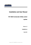
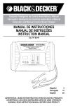
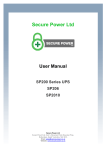
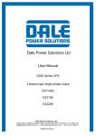
30KVA ID:01 ◄ 22-12-2008 08:30 ONLINE Command Setting Record ► Version Single Battery Volt. 12V Battery Number 20 Battery Group 1 Battery Number Single Battery Capa. 100AH Boost Upper Limit Volt. 2.31 ▼ 20 ▲ Float Base Volt. 2.25 Battery Protect Volt. Ensure Cancel1.70 Boost Charge Enable Boost Last Time 231 Min Max Charge Current 25A 30KVA ID:01 ◄ Command ◄ Setting Battery Protect Volt. Ensure Boost Charge Boost Last Time Max Charge Current Back Next 22-12-2008 08:30 Record 30KVA ID:01 ► Version ◄ 1000 7 8 9 Cancel 4 5 6 ← 1 2 3 → 0 Ensure Setting of single battery capacity 30KVA ID:01 ◄ ONLINE Command Setting Record ◄ Command Setting Record Command 30KVA ID:01 ► Version ONLINE Back Next Setting Record 22-12-2008 08:30 ◄ Back Next Single Battery Volt. 12V Battery Number 20 Battery Group Boost Charge 1 Single Battery Capa. 100AH Boost Upper Limit ▼ Volt. Enable ▲ 2.31 Float Base Volt. 2.25 Battery Protect Volt. Ensure Cancel1.70 Boost Charge Enable Boost Last Time 231 Min Max Charge Current 25A Back Next Command ONLINE Setting Record 22-12-2008 08:30 ► Version Back Next Setting of battery low protection voltage 22-12-2008 08:30 Version ► Version Single Battery Volt. 12V Battery Number 20 Battery Group Bat. Protect Volt. 1 Single Battery Capa. 100AH Boost Upper Limit Volt. 2.31 ▼ 1.28 ▲ 2.25 Float Base Volt. Battery Protect Volt. Ensure Cancel1.70 Boost Charge Enable Boost Last Time 231 Min Max Charge Current 25A Setting of float base charge voltage ONLINE 12V 20 1 100AH 2.31 2.25 Cancel1.70 Enable 231 Min 25A Setting of boost charge voltage upper limit 22-12-2008 08:30 Single Battery Volt. 12V Battery Number 20 Battery Group Float Base Volt. 1 Single Battery Capa. 100AH Boost Upper Limit Volt. ▼ 2.28 ▲ 2.31 Float Base Volt. 2.25 Ensure Cancel1.70 Battery Protect Volt. Boost Charge Enable Boost Last Time 231 Min Max Charge Current 25A 30KVA ID:01 ► Version Single Battery Volt. 12V Battery Number 20 Battery Group 1 Boost Volt. Single Battery Capa. 100AH Boost Upper Limit Volt. 2.31 ▼2.32▲ Float Base Volt. 2.25 Battery Protect Volt. Ensure Cancel1.70 Boost Charge Enable Boost Last Time 231 Min Max Charge Current 25A Single Battery Capa. . Record Setting of battery group ONLINE Command Setting Single Battery Volt. Battery Number Battery Group Battery Group Single Battery Capa. Boost Upper Limit Volt. ▼ 1 ▲ Float Base Volt. Setting of battery number 30KVA ID:01 22-12-2008 08:30 ONLINE 30KVA ID:01 ► ◄ Command ONLINE Setting Record 22-12-2008 08:30 Single Battery Volt. 12V Battery Number 20 Battery Group Boost Last Time 1 Single Battery Capa. 100AH Boost Upper Limit Volt. 2.31 ▼ 231 ▲ Float Base Volt. 2.25 Battery Protect Volt. Ensure Cancel1.70 Boost Charge Enable Boost Last Time 231 Min Max Charge Current 25A Back Next Setting of boost charge ► Version Back Next Setting of boost charge lasting time 25 30KVA ID:01 ◄ ONLINE Command Setting Record 22-12-2008 08:30 ► Version Single Battery Volt. 12V Battery Number 20 Battery Group Max Charge Current 1 Single Battery Capa. 100AH Boost Upper Limit Volt. 2.31 ▼ 25 ▲ Float Base Volt. 2.25 Battery Protect Volt. Ensure Cancel1.70 Boost Charge Enable Boost Last Time 231 Min Max Charge Current 25A Back Next Setting of max. Charge current 4.3.2 UPS Module LCD display 1) Below main interface comes out when power is connected or the system is cold started. Shown as the picture below. 10KVA Main interface 2) Press any key, it will change to the basic status interface,Shown as the picture below. MODE:On-Line Volt:AN BN CN Vin: 220 219 221 Vout:220 Basic status interface 3) Press the ◀ or ▶ button, it will change to main menu, Shown as the picture below. Figure Status Setting Main menu 4) An arrow icon will come out on the LCD when pressing the ENT, then, the data info, status info, setting information can be selected by pressing the right or left arrow button, and checking the details by pressing them. 5) Select and confirm the data information can view the details. It contains the details of the AC input /output , inverter, battery , BUS, parallel and temperature,Shown as the pictures below. Figure Mains A:225.9 B:224.8 C:225.5 Figure Output 220.0V 0.0A 50.0HZ Load: 0% MAIN INPUT INFO OUTPUT INFO 26 Figure Output 0KW 0KVA PAK: 0 OUTPUT INFO Figure Invert 220.0V 50.0HZ INVERT INFO Figure BUS -360V +360V BUS INFO Figure PBatt. Discharge 0V 0.0A Figure NBatt. Discharge 0V 0.0A BATTERY INFO BATTERY INFO Figure Parallel ID ID:01 Figure Temperature 00℃ PARALLEL INFO TEMPERATURE INFO 6) Select and confirm the status info below to view the details, including status information, alarm information, code, power rating and version. Shown as the pictures below. Status State Alarm & Fault Rated POWER main menu Status Rated POWER Code Version main menu Status State Curstate:Init SWMB OFF Status Alarm & Fault status info Alarm info Status Code/Status 01 0x00 02 0x000000 code info Status Rated POWER MachInfo:0101 Rated: 10KVA type info Status Version LCD Ver:D000B001 DSP Ver:D000B001 version info 7) Select and confirm setting menu. The setting information well be displayed which includes client setting and system setting, Shown as the picture below. Setting User System Set Set setting menu 8) Select and confirm client setting ,then you may set the following: Setting User Set BL. ON BackLight 2 User setting information 27 9)Select and confirm system setting menu,then: Setting Power Walk In On Buzzer Stop System setting 10) Warning messages are shown as the pictures below. Warning! Set no Echo:31 no echo for setting Warning! Set Error:31 Warning! Interrupt switch prompt Sure:Ent No:ESC error for setting switch delay Warning! Off will cause sys.Overload Sure:Ent No:ESC overload due to shutdown Warning! Off will cause output failure Sure:Ent No:ESC no output due to shutdown Warning! Switch Limited Sure:Ent switch times 4.3.3 Monitoring module control panel Monitoring module control panel is at UPS top. Through this control panel and LED, the operator may monitor all measured datas, UPS & battery status, and alarm events. Power supply switch EPO 1) Power supply switch: the power supply switch of the monitoring module. After switch it off, the monitoring module can be hot swapped. 2) EPO KEY: Disconnects Power to the Load. Disables rectifier, inverter, static bypass and battery operation 3) MAINS INDICATOR (LED): the status of the AC Input 4) INVERT INDICATOR (LED): the status of the inverter 5) OUTPUT INDICATOR (LED): the status of the output 6) BYPASS INDICATOR (LED): the status of the bypass Input 7) BAT INDICATOR (LED): the status of the battery 8) FAULT INDICATOR (LED): UPS is faulty 9) ALARM RESET: to reset alarm. 10) MUTE: MUTE function of monitoring module, to mute buzzer, The buzzer will be re-started automatically when fault occurs. 11) INVERTER OFF KEY: Disable Inverter Operation 28 12) INVERTER ON KEY: Enable Inverter Operation CAUTION! The LEDs mounted on the mimic flow chart represent the various power paths and current UPS operational status. Mains indicator Green Rectifier in Normal Operation Flashing Green Input mains voltage or frequency out of normal range Off Input AC Not Available Battery indicator Battery Normal, but discharging and powering the load Battery End of Discharge pre-warning, Battery abnormal (high Flashing Green or low voltage, Absent or Polarity Reversed), charger abnormal Green Off Battery and Converter Normal, Battery charging. Bypass indicator Load on Bypass power Bypass not available, out of normal range, Static bypass Flashing Green switch short or broken fault, bypass switch wiring fault, bypass over current Green Off Bypass Normal, load not on bypass Inverter indicator Inverter Normal and powering the load Inverter failed, Inverter IGBT bridge direct conduct Flashing Green protection, Inverter Thyristor short or broken fault, over load or Parallel Overload, Feedback protection Green Off Inverter not operating Output indicator Green Off UPS output ON and Normal UPS output OFF. Ffault indicator Off Red Normal Operation UPS fault e.g. 29 4.4 Display Messages/Troubleshooting This section lists the event and alarm messages that the UPS might display. The messages are listed in alphabetical order. This section is listed with each alarm message to help you troubleshoot problems . Display messages Events: No. 1 2 3 Display message Initializing Standby Non-Output Meaning The DSP and MCU are in Initializing. 4 On Bypass 5 On Line The UPS does not provide power to the load equipment. Inverter output is turned off and the load connected at the inverter output receives power from utility line via STS. Inverter output power is the primary energy source to load 6 7 8 9 10 11 12 13 14 EPO Activated Automatic Self Test Inverter in soft starting System Fault Detected MBS status EPO status Int. Input Switch closed Int. Input Switch opened Rectifier Deactivated Emergency Power Off Switch has been activated. The UPS has started pre-programmed battery test. The inverter is in soft-starting The system has detected an internal error status of maintenance bypass status of EPO(emergency power off) The internal input breaker is closed manually. The internal input breaker is opened manually. The rectifier has been deactivated. 15 Rectifier Activated 16 Rectifier Current Limit The rectifier has been activated. When the input voltage is at 208V~305V, the output of the UPS will not be interrupted, but it will be at current limit, for example, to reduce charge current. When the load connected exceeds its limit, the warming shall occur. 17 Battery charge deactivated The charger has been deactivated. 18 Positive Battery Boost Charging The Positive battery is in boost charge, which is Constant voltage boost charge mode or constant current boost charge mode. 22 23 24 25 26 27 28 29 Positive Battery Float Charging Negative Battery Boost Charging Negative Battery Float Charging Int. bypass Switch Opened Int. bypass Switch Closed Int. output Switch Opened Int. output Switch Closed Ext. bypass Switch Opened Ext. bypass Switch Closed Ext. output Switch Opened Ext. output Switch Closed 30 Coming to Interval transfer 19 20 21 The Positive battery is in float charge. The Negative battery is in boost charge. The Negative battery is in float charge. The internal bypass breaker is opened manually The internal bypass breaker is closed manually The internal output breaker is opened manually The internal output breaker is closed manually The external bypass breaker(parallel system) is opened The external bypass breaker(parallel system) is closed The external output breaker(parallel system) is opened The external output breaker(parallel system) is closed Allows transfer to bypass or inverter with 3/4 cycle break. Use of this command will drop load. 30 34 Coming to over load due to inverter off Coming to Interval transfer due to inverter off Inverter invalid due to over load Inverter Master 35 Transfer Times-out 31 32 33 36 37 38 39 40 41 42 43 44 45 46 47 48 49 UPS In shutdown Due To Overload. UPS In Bypass Due To Overload. Parallel in Bypass LBS Activated Lightning Protection Battery low to UPS OFF UPS timing on UPS timing OFF timing self-test start Stop self-test manual OFF remote OFF module connected module removed When the inverter is turned off manually, the load will exceed the power capacity. When the inverter is turned off manually, the load will exceed the power capacity. The load exceeds the capability of the single or parallel modules. It indicates the Master Inverter. Latched load transfer to bypass as a result of too many successive transfers within the current hour. Automatic reset attempt within the next hour. The load exceeded the power capacity. The UPS has been shutdown The load exceeded the power capacity. The UPS has switched to Bypass Mode. The parallel system has switched to bypass mode LBS has been activated. Lightning protector has been activated. battery voltage lower than protection point UPS on at certain time UPS off at certain time start to self-test at certain time self-test stops turn off UPS manually turn off UPS remotely module is connected module is removed Alarm Information No. Display message 1 Rectifier Fault 2 Rectifier Over Temperature 3 Inverter Over temperature 4 5 6 7 Rectifier over-current Input thyristor failure Battery discharge thyristor failure Battery charge thyristor failure 8 Fan fault 9 DC Bus over-voltage 10 DC Bus under-voltage 11 DC bus unbalance 12 Soft start fault 13 Input Neutral line missing 14 15 Battery Reverse No Battery Positive Battery Charger fault 16 Meaning Rectifier detected faulty. Rectifier and inverter and charger shut down. The temperature of heatsink is too high to keep the rectifier running. Charger and inverter shut down. The temperature of the inverter heatsink is too high to keep inverter running. Rectifier failure due to over-current Failure of input thyristor Failure of battery discharge thyristor Failure of battery charge thyristor At least one of the cooling fans fails. Rectifier and inverter and charger shut down. Rectifier, inverter and battery converter are shutdown due to high DC bus voltage. Rectifier, inverter and battery converter are shutdown due to low DC bus voltage. If the difference between positive DC bus and negative DC bus exceeds 30V, this warning shall occur. Rectifier could not be started due to low DC bus voltage If Input Neutral line is missing or disconnected while the UPS is in operation, the UPS will generate Neutral line failure alarm and go into Battery mode. The polarity of the battery is reversed. Battery is disconnected The positive battery Charger is fault. The charger will be shut down. 31 17 Negative battery charger fault 18 Battery under-voltage 19 Battery over-voltage 20 Battery under-voltage pre-warning 21 Mains freq. abnormal 22 Mains volt. Abnormal 23 Inverter fault 33 Inverter IGBT bridge direct conduct protection Inverter Thyristor short fault Inverter Thyristor broken fault Bypass Thyristor short fault Bypass Thyristor broken fault CAN comm. Fault Parallel system load sharing fault Bypass Site Wiring Fault System Not Synchronized To Bypass. Bypass unable to trace 34 Bypass Not Available 35 IGBT over current 36 Parallel cable connection error 37 Parallel relay fault 38 LBS Not SYNC. 39 initialization fault 40 41 Inverter is invalid Overload 42 Parallel Overload 43 DC component over limitation 44 Bypass over current 24 25 26 27 28 29 30 31 32 The negative battery charger is fault. The charger will be shut down. The battery voltage is too low and the charger has been deactivated. The battery voltage is too high and the charger has been deactivated. The UPS is in battery operation and the battery voltage is low. Note: Runtime is limited in duration. Mains frequency is out of limit range and results in rectifier shutdown. Mains Voltage exceeds the upper or lower limit and results in rectifier shutdown. When inverter has been turned on for a certain time, but the output voltage of inverter is still out of the range of Rating voltage +12.5% and –25%, inverter fault will occur, and the inverter will be shut down and UPS will transfer to bypass. This fault cannot be cleared until this unit is completely powered off. If the two IGBTs in the same bridge of inverter are on simultaneously, inverter should be shut down SCR at the inverter side is short-circuited SCR at the inverter side is open-circuited SCR at the bypass side is short-circuited SCR at the bypass side is open-circuited The CAN bus communication fails If any unit in a parallel system has an unbalance load share that exceeds 30%, this warning will occur. Wrong phase rotation on the bypass side. System cannot synchronize to bypass. Bypass Mode may not be available. Bypass is unable to trace The frequency or voltage is out of acceptable range for bypass. This message occurs when the UPS is online, and indicates that the bypass mode may not be available if required. IGBT current is over limit. If a unit is set as parallel mode, but parallel cable is not connected correctly, this warning will occur Relay of parallel circuit must be turned on when the system are in parallel and the inverter is on. If the relay of parallel circuit cannot be turned on correctly, this unit should be shut down (include inverter and bypass). This fault cannot be cleared until this unit is completely powered off. Two parallel systems are not in synchronization. When the procedure of initialization is wrong, this warning will occur. The inverter on button has been activated. The load exceeds the system power capacity. The UPS parallel system is confirmed to be overloaded according to the set number. If the DC component of the UPS output rating power is larger than the limitation, this warning should occur When the bypass current exceeds the limitation, this alarm will occur. 32 45 46 47 48 49 50 This UPS is fitted with a voltage free contact closure signal for use with an external automatic disconnect device (by others) to protect against back-feeding voltage into the incoming bypass supply External fire detector has been activated. External smoke detector has been activated. battery has been damaged, this warning shall occur. battery over-temperature, this warning shall occur. Model setting of the UPS is incorrect. Feedback protection Ext. Fire Alarm Ext. Smoke Alarm battery damaged battery over-temperature model set wrong 4.5 Options Network Management Card with Environmental Monitoring CAUTION! For network management configuration and use, refer to the separate user manual - Network Management Card with Environmental Monitor - shipped with the CARD. Network Management Card replacement 1:Intelligent Network Port 2:SNMP port SNMP card: internal SNMP / external SNMP optional ◆ Loosen the 2 torque screws (on each side of the card). ◆ Carefully pull out the card. Reverse the procedure for re-installation The slot called SNMP supports the MEGAtec protocol. We advise that NetAgent II-3 port is also a tool to remotely monitor and manage any UPS system the overview of the SNMP card 33 NetAgent II-3Ports supports the Modem Dial-in(PPP) function to enable the remote control via the internet when the network is unavailable . In addition to the features of a standard NetAgent Mini, NetAgent II has the option to add NetFeeler Lite to detect temperature, humidity, smoke and security sensors. Thus, making NetAgent II a versatile management tool. NetAgent II also supports multiple languages and is setup for web-based auto language detection . Typical topology of the UPS Network Management Relay card A 10-pin terminal is supported to offer the signals of Bypass, Utility Failure, Inverter On, Battery Low, UPS fault, UPS Alarm, and UPS Shutdown. The relay communication card contains six dry contact outputs and one dry input. The inputs and outputs are factory programmed according to functions listed in the table Table:Relay Contacts (communication card) Port Function 1 Utility Failure 2 / 3 Battery Low 4 On Bypass Output 5 UPS Fault 6 Inverter On 7 UPS Alarm 8 COM 9 +12V EPO Input 10 34 0V CAUTION! The output contacts numbers for a second relay board installed will be 1 to 7. Contacts are NO (normally open) type. available at no charge in any of Overview of the relay card Appendix 1 Specifications UPS Cabinet Capacity (VA/W) Input Model 30KVA 4~6KVA /3.2~24KW 50KVA 4~10KVA /3.2~40KW 100KVA 4~10KVA /3.2~80KW UPS Module 4KVA/3.2KW, 6KVA/4.8KW, 10KVA/8KW Phase 3Phase/4Wires + Ground or 1Phase 2 Wires + Ground Rated Voltage Voltage Range Frequency Range Power Factor 380/400Vac or 220/230VAC 208~478Vac or 120VAC-276VAC 40~70Hz ≥0.99 Current Harmonic Max.voltage: +15%(optional +5%、+10%、+25% ) Min. voltage: -45% (optional -20%、-30%) Frequency protection range: ±10% ≤5%(100% non-linear load) Phase Single phase & Ground Rated Voltage Power Factor Voltage Precision Utility Mode Output Frequency Battery Mode Crest Factor 220/230VAC 0.8 ±2% ±1%、±2%、±4%、±5%、±10% of the rated frequency(optional) Bypass Voltage Range Output 20KVA 4KVA /3.2~16KW Transfer Time (50/60±0.2%)Hz 3:1 Utility to Battery : 0ms Utility to bypass : 0ms (following) 35 Overload Capacity Load≤110%,60min,≤125%,last 10min,≤150%last 1min,≥150% shut down UPS immediately THD ≤2% with linear load ≤5% with non linear load Normal mode≥90% Efficiency Comunicatio n Interface UPS cabinet RS232,Optical coupler dry contact,RS485, SNMP card(optional),Centralized monitoring card(optional) UPS module RS232 Voltage ±96V\±108V\±120V DC; battery quantity(optional) UPS Maximum current 30A Maximum current 60A cabinet Charge Current(A) UPS Maximum current 6A module Backup time Depends on the capacity of external batteries Battery Operating Environment Temperature 0℃~40℃ Humidity 0~95% non condensing Storage temperature -25℃~55℃ Altitude < 1500m Unit Dimensions(W*D*H ) Other Weight (Kg) UPS cabinet 600*840*1400mm 600*840*2000mm UPS 443x580x131 mm module UPS 150 180 cabinet 4KVA: 21 UPS 6KVA: 23 module 10KVA: 25 Industry Standard CE,EN/IEC 62040-2,EN/IEC 62040-1-1 Appendix 2 UPS message table 1. The Inner Code is applied to This Series. The following format block is Inner Code display on LCD: AAAA–AAAA BBBB-BBBB EEFF CCCC-CCCC DDDD-DDDD 2. The part of Inner Code means AAAA-AAAA(Rectifier State): Byte 1 8 4 2 1 3 3 5 5 6 6 7 7 7 9 9 A B C D E F Int. Input Switch closed C D E F Rectifier Activated A B E F Emergency Power off B C D F Rectifier current Limt 36 8 4 2 1 3 3 5 6 6 5 7 7 7 9 9 A B C D E F Input Power work on C D E F Power by Input A B E F Battery Test B C D F Battery Charge Byte 2 8 4 2 1 3 3 5 6 6 5 7 7 7 9 8 4 2 1 3 3 5 6 6 5 9 7 7 7 9 A B C D E F P-Battery Boost Charge C D E F N-Battery Boost Charge A B E F C B D F 9 A B C D E F C D E F A B E F B C D F 9 A B C D E F communication connected 9 C D E F A B E F B C D F Byte 3 8 4 2 1 3 3 5 6 6 5 7 7 7 8 4 2 1 3 3 5 6 6 5 7 7 7 9 9 A B C D E F C D E F A B E F B C D F BBBB-BBBB(Inverter State): Byte 1 8 4 2 1 3 3 5 6 6 5 7 7 7 9 8 4 2 1 5 3 3 6 7 6 7 5 9 7 9 9 A B C D E F Int. bypass Switch Closed C D E F Int. output Switch Closed A B E F Manu-Bypass Switch B C D F Closed Ext. bypass Switch Closed A B C D E F Ext. output Switch Closed C D E F 00:Shut Down, 01:Inv starting, 10 : Inv work on ,but No A B C E F Output 11:Normal Output B D F Output by Inv Byte 2 8 4 2 1 5 3 3 5 6 6 9 7 7 7 9 A B C D E F C D E F A B E F C B D F 37 Output by Bypass Cue: Interval Transfer Cue: trun-off, System will be broken Cue:trun-off,Parallel will be overloaded 8 9 A B C D E F Emergency Power off 4 5 6 7 C D E F INV.invalid due to Overload 2 3 6 7 A B E F Change Master C 1 3 5 7 9 B D F Transfer Times-out Byte 3 8 4 2 1 5 3 3 6 6 5 2 1 3 3 5 7 6 6 5 A B C D E F Shutdown Due To Overload On Bypass Due To Overload Parallel in Bypass 9 C D E F A B E F C B D F A B C D E F C D E F A B E F B C D F INV standby 7 7 8 4 9 9 7 7 7 9 LBS Activated CCCC-CCCC(Rectifier Alarm) : Byte 1 8 4 2 1 5 3 3 6 7 6 7 5 9 C D E F Rectifier over temperature A B 7 9 8 4 2 1 3 3 5 6 6 5 A B C D E F Rectifier fault 7 7 7 B 9 9 E F Inverter over temperature C D F Rectifier over current A B C D E F C D E F A B E F C B D F Auxiliary power 1 fault Auxiliary power 2 fault Input Thyristor failed Discharge Thyristor failed A B C D E F C D E F A B E F C B D F Charge Thyristor failed Fan fault Fan Power fault DC Bus over voltage Byte 2 8 4 2 1 3 3 5 6 6 5 7 7 7 9 8 4 2 1 5 3 3 6 7 6 7 5 9 9 A A 7 9 B C D E F DC Bus below voltage C D E F DC bus unbalance E F Mains Site Wiring Fault F Soft start failed B B C D Byte 3 8 4 2 1 3 3 5 5 6 6 7 7 7 9 9 A B C D E F C D E F A B E F C B D F 38 Input Neutral line missing Battery reverse No battery P-Battery Charger fault 8 4 2 1 3 3 5 6 6 5 7 7 7 9 9 A B C D E F N-Battery Charger fault C D E F Battery under voltage A B E F Battery over voltage B C D F Battery low pre-warning Byte 4 8 4 2 1 3 3 5 6 6 5 7 7 7 9 8 4 2 1 3 3 5 6 6 5 9 7 7 7 9 9 A B C D E F Mains freq. abnormal C D E F Mains volt. Abnormal A B E F C B D F A B C D E F C D E F A B E F B C D F DDDD-DDDD(Inverter Alarm): Byte 1 8 4 2 1 3 3 5 6 6 5 7 7 7 9 8 4 2 1 3 3 5 6 6 5 9 7 7 7 9 9 A B C D E F Inverter fault C D E F Inv. IGBT bridge shorted A B E F Inverter Thyristor short C B D F Inverter Thyristor broken A B C D E F Bypass Thyristor short C D E F Bypass Thyristor broken A B E F CAN comm. Fault B C D F Parallel load sharing fault Byte 2 8 4 2 1 3 3 5 6 6 5 7 7 7 9 8 4 2 1 3 3 5 6 6 5 9 7 7 7 9 9 A B C D E F Bypass Site Wiring Fault C D E F System not Sync. to Bypass A B E F Bypass unable to trace C B D F Bypass Not Available A B C D E F IGBT over current C D E F Fuse broken A B E F Cable connection error C B D F Parallel relay fault Byte 3 8 4 2 1 3 3 5 6 6 5 7 7 7 9 8 4 2 1 3 3 5 5 6 6 7 7 7 9 9 9 A B C D E F LBS Not SYNC. C D E F Initializtion fault A B E F Inverter on invalid B C D F Overload A B C D E F Parallel Overload C D E F DC component over limit. A B E F Bypass over current C B D F Feedback protection 39 Byte 4 8 4 2 1 3 3 5 6 6 7 7 7 5 8 4 2 1 3 3 5 6 6 7 7 7 5 9 A B C D E F BUS voltage abnormal 9 C D E F A B E F B C D F 9 9 A B C D E F C D E F A B E F B C D F EE(Inside Monitor): Byte 1 8 9 A B C D E F Generator Connect 4 5 6 7 2 3 6 7 1 3 5 7 C D E F ShutDown Due To Batt. Low A B E F Time to turn on 9 B C D F Time to turn off 8 9 A B C D E F timing self test start C D E F Surge protection active signal, from monitoring board IO 6 7 A B E F battery monitoring system C connected 5 7 9 B D F system unregistered 4 5 6 7 2 3 1 3 FF(Monitoring) Byte 1 8 9 A B C D E F Battery Falut (from battery monitoring) 4 5 6 7 2 3 1 3 6 7 5 7 C D E F Battery over temperature (from battery monitoring) A B C E F Battery over voltage (from battery monitoring) 9 B D F Battery under voltage (from battery monitoring) 8 9 A B C D E F External Fire Alarm (from monitoring board IO) 4 5 6 7 C D E F External Smoke Alarm (from monitoring board IO) 2 3 1 3 6 7 5 7 A B E F UPS model wrong C 9 B D F time up for maintenance 40 suggested Appendix 3 Problems and Solution In case the UPS can not work normally, it might be wrong in installation, wiring or operation. Please check these aspects first. If all these aspects are checked without any problem, please consult with local agent right away and provide below informations. (1) Product model name and serial number, which can be found in LCD display. (2) Try to describe the fault with more details, such as LCD display info, LED lights status, etc. Read the user manual carefully, it can help a lot for using this UPS in the right way. Some FAQ (frequently asked questions) may help you to troubleshoot your problem easily. No. Problem Possible reason The network cable is not fixed properly or the telephone line of the front door is not fixed properly. Solution Connect the network cable telephone cable properly. and 1 LCD not display 2 LCD Blue screen LCD is Interferenced Take out the cable and insert back properly Utility is connected but the UPS can not powered ON. Input power supply is not connected; Input voltage low; The input swith of the module is not switched on . measure if the UPS input voltage/frequency are within the window. Check if all modules input are switched on The input breakers of the Modules are not switched on; input cable is not well connected Switch on the input breaker; Make sure the input cable is well connected. Output cable does not well connected Make sure the output cable is well connected. 3 4 5 6 7 8 Utility normal but Utiltiy LED does not light on, and the UPS operates at battery mode The UPS does not indicate any failure, but output do not have voltage Module does not well inserted; The UPS module Pull out the module and insert again; The left coronal screw is not Tighten the screw; can not transfer to tight. Switch on the output breaker. bypass or inverter Output breaker do not switch on The UPS module The module is already Take out this module, replace with a fault LED remains new module. damaged ON Utility flashing LED is Utility voltage exceeds UPS input range. 41 If the UPS operates at battery mode, please pay attention to the remaining backup time needed for your system. 9 10 11 12 13 14 15 Battery LED is flashing but no charge voltage and current Battery breaker does not switch on, or batteries are damaged, or battery is reversely connected. battery number and capacity are not set correctly. Buzzer beeps every 0.5 seconds and Overload LCD display “output overload” Buzzer long beeps, The UPS output is in short LCD display “output circuit short circuit” Switch on the battery breaker. If batteries are damaged, need to replace whole group batteries, Connect the battery cables correctly; Go to LCD setting of the battery number and capacity, set the correct data. remove some load Make sure the load is not in short circuit, then restart the UPS. The LED of the Module with RED light The module is not inserted properly. Pull out properly. The UPS only works on bypass mode The UPS is set to ECO mode, or the transfer times to bypass mode are limited. Set the UPS working mode to Single Module type(non-parallel) or to reset the times of transferring to bypass or re-start the UPS Can not Black start Battery switch is not properly closed; Battery fuse is not open; Or Battery low Close the battery switch; Change the fuse; Recharge the battery Buzzer beeps continuously and LCD indicates Rectifer fault or output fault UPS is out of order 42 the module and insert Consult with your local agent for repair Appendix 4 RS232 communication port definition Definition of Male port: Connection between PC RS232 port and UPS RS232 port PC RS232 port UPS RS232 port Pin 2 Pin 2 Pin 3 Pin 3 UPS send,PC receive PC send,UPS receive Pin 5 Pin 5 ground Available function of RS232 ◆ Monitor UPS power status。 ◆ Monitor UPS alarm info。 ◆ Monitor UPS running parameters。 ◆ Timing off/on setting。 RS-232 communication data format Baud rate ---------- 2400bps Byte length ---------- 8bit End bit ---------- 1bit Parity check --------- 43