1
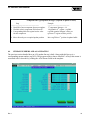
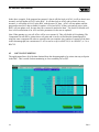
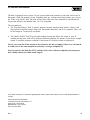
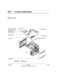
Field Automation Systems
GAS CHROMATOGRAPH SERIAL I/O MODULE
User Manual
Form A6098
(for QERs 00Q018 & 00Q020)
July 2000
GC Interface User Manual
Revision Tracking Sheet
July 2000
This manual may be revised from time to time to incorporate new or updated information. The revision
level of each page is indicated at the bottom of the page opposite the page number. A major change in
the content of the manual also changes the date that appears on the front cover. Listed below is the
revision level of each page.
Page
Revision
All Pages
Rev 1 (dated 7/00)
(Note: This manual is based on Vinson Controls’ GCI software Version 2.0, Release 3.)
© Fisher Controls International, Inc. 2000. All rights reserved.
Printed in the U.S.A.
While this information is presented in good faith and believed to be accurate, Fisher Controls does not guarantee satisfactory results from
reliance upon such information. Nothing contained herein is to be construed as a warranty or guarantee, express or implied, regarding the
performance, merchantability, fitness or any other matter with respect to the products , nor as a recommendation to use any product or process
in conflict with any patent. Fisher Controls reserves the right, without notice, to alter or improve the designs or specifications of the products
described herein.
Rev 1
2
GC Interface User Manual
Table of Contents
SECTION 1 — GETTING STARTED ...................................................................................................5
1.1
INTRODUCTION.........................................................................................................................5
SECTION 2 — SERIAL I/O USER PROGRAM ..................................................................................6
2.1
USER PROGRAM OVERVIEW ..................................................................................................6
2.2
USER PROGRAM NAMES .........................................................................................................6
2.3
USER PROGRAM INSTALLATION ..........................................................................................7
2.3.1
Preparing to Download the Program.......................................................................................7
2.3.2
Download Procedure...............................................................................................................7
SECTION 3 —GAS CHROMATOGRAPH APPLICATION OVERVIEW......................................9
3.1
HARDWARE (SERIAL I/O MODULE) ......................................................................................9
3.1.1
Module types and wiring methods..........................................................................................9
3.2
COMMUNICATION MODES ...................................................................................................10
3.3
GC APPLICATION PROGRAM LOGIC ..................................................................................10
3.3.1
Gas Component ID Codes ....................................................................................................11
3.3.2
Assigning Streams to ROC AGAs........................................................................................11
3.3.3
Soft Point Writing.................................................................................................................11
SECTION 4 — CONFIGURATION.....................................................................................................12
4.1
USER POINTS ............................................................................................................................12
4.2
GAS CHROMATOGRAP H POLLING TEMPLATE................................................................13
4.3
COMPONENT IDS .....................................................................................................................16
4.4
STREAM NUMBERS AND AGA UPDATING........................................................................18
4.5
SOFT POINT WRITING ............................................................................................................19
3
Rev 1
GC Interface User Manual
[This page is intentionally left blank.]
Rev 1
4
GC Interface User Manual
SECTION 1 — GETTING STARTED
1.1
INTRODUCTION
This document covers the use of Fisher Controls Serial I/O Module programmed with the Gas
Chromatograph application.
The Gas Chromatograph application, which is embedded in a Serial I/O Module (either RS232 in
00Q018, or RS485 in 00Q020) allows the ROC/FloBoss to communicate with a Daniel gas chromatograph without having to use a communications port. It is designed to be a “plug and play” application
but also to be flexible in its configuration. It gathers and validates chromatograph data, updates the
parameters of multiple AGA runs directly from multiple GC streams, triggers Fpv recalculations and
optionally writes any GC data to user-specified Soft Points.
This manual describes how to install the application-independent Serial I/O User Program (.H00 file)
required for operation with the Serial I/O Module. It also describes the logic and configuration of the
gas chromatograph application resident in the module.
5
Rev 1
GC Interface User Manual
SECTION 2 — SERIAL I/O USER PROGRAM
2.1
USER PROGRAM OVERVIEW
The Serial I/O User Program handles the communication between the Serial I/O Module and the ROC or
FloBoss. The user program, which is application-independent, consists of a downloadable .H00 file. It
allows user-defined points (defined by the module) to be created and maintained in the ROC/FloBoss. It
also has the ability to read and write standard point type parameters in the ROC and allows direct
memory read/write operations (historical, events, etc).
2.2
USER PROGRAM NAMES
The Serial I/O User Program runs on a ROC312, ROC364 or ROC407 (FloBoss 407) unit with the
following hardware:
•
•
•
ROC312 with ROCPAC version 1.10 or any FlashPAC version.
ROC364 with ROCPAC version 1.70 or any FlashPAC version.
ROC407 with firmware version 1.04 or greater.
The downloadable program names are (all run in User1 task except where noted):
SIO_B060.H00 – Serial I/O user program with code residing in segment B000 and data in segments
6000/6400. ROC407 only.
SIO_B8A8.H00 – Serial I/O user program with code residing in segment B800 and data in segments
A800/AC00. ROC312/ROC364 (ROCPAC with RAM Module or FlashPAC).
SIO_C0C8.H00 – Serial I/O user program with code residing in segment C000 and data in segments
C800/CC00. ROC312/ROC364 with ROCPAC.
SIO_D0B0.H00 – Serial I/O user program with code residing in segment D000 and data in segment
B000/B400. ROC312/ROC364 with FlashPAC.
SIO_D0D8.H00 – Serial I/O user program with code residing in segment D000 and data in segments
D800/DC00. ROC312/ROC364 with ROCPAC.
SIO_7060.H00 – Serial I/O user program with code residing in segment 7000 and data in segments
6000/6400. ROC407, or ROC312/ROC364 with ROCPAC and RAM Module.
SIO3D8B8.H00 – Serial I/O user program with code residing in segment D800 and data in segments
B800/BC00. ROC312/ROC364 with FlashPAC. Note: Runs in User3 task.
Rev 1
6
GC Interface User Manual
2.3
USER PROGRAM INSTALLATION
This section provides instructions for installing the user program into ROC/FloBoss memory. The Serial
I/O Module should be installed in an I/O slot before downloading the program.
2.3.1
Preparing to Download the Program
To install the user program, connect an IBM-compatible computer containing ROCLINK Configuration
Software (version 2.20 or later) to the ROC Operator Interface port. Before the downloading process is
started, make sure the RAM is available in the ROC for the file intended to be downloaded. RAM
availability can be checked by selecting File, Download, User Programs in ROCLINK. This brings up a
screen similar to the one shown below. Check the unused memory blocks to determine availability.
2.3.2
Download Procedure
The download procedure in this section requires ROCLINK Configuration Software, version 2.20 or
greater.
To download the program, select File from the menu bar, select Download... from the File menu and
select User Programs from the Download menu. The following screen appears:
7
Rev 1
GC Interface User Manual
This screen shows all of the programs currently loaded along with their memory usage and shows all the
unused memory segments available.
Select the Download pushbutton in the lower left-hand corner. An Open File dialog box appears.
Make the appropriate selections in the Directory/Drive box to get to the directory containing the user
program. The user program should appear in the file window. Select the desired user program and press
“Enter.” The screen shown above reappears with the selected path and filename displayed below the
unused memory segments. Click on the Download button again and the user program will download into
the ROC. The progress of the download can be seen on the status bar at the bottom of the screen. When
the download is complete, the user program will display at the top of the screen as shown below.
At this point, the user program is loaded and running.
Rev 1
8
GC Interface User Manual
SECTION 3 —GAS CHROMATOGRAPH APPLICATION OVERVIEW
3.1
HARDWARE (SERIAL I/O MODULE)
The application is embedded in a Serial I/O Module. The module contains an 8-bit Motorola
Microcontroller with 1K RAM and a 32K external EEPROM. The Microcontroller’s CPU handles the
communications with the chromatograph, processes the application logic and builds the data messages
for the ROC. This modularity off-loads these tasks from the ROC CPU. The only load on the ROC is
when the user program exchanges data with the Serial I/O Module.
The Serial I/O Module can be placed into any I/O module slot in the ROC. The user program will
support up to ten Serial I/O Modules.
3.1.1
Module types and wiring methods
There are two types of Serial I/O Modules providing the gas chromatograph application: RS232 and
RS485.
The RS232 method can be used for distances up to 50 feet. The RS232 module does not support
RTS/CTS. It uses three conductors (TX, RX, COM) connected to terminals A, B, and C as shown
below.
The RS485 method can be used for distances of up to a few thousand feet. This method supports
multiple field devices (multi-drop). It uses two conductors ( +, -) connected to terminals A and B as
shown below.
SERIAL I/O
RS-232
O
A
B
C
9
SERIAL I/O
RS-485
O
TX
RX
COM
A
B
C
+
–
N/C
Rev 1
GC Interface User Manual
3.2
COMMUNICATION MODES
The gas chromatograph application uses Modbus protocol to communicate to the gas chromatograph.
The module acts as a Modbus master and polls the chromatograph for the required floating point and
integer registers. The module can communicate at rates up to 9600 baud. The application supports both
RTU and ASCII modes. User-configurable Comm Parameters include: GC Address and Stream #, RTU
or ASCII mode, Byte Order, Baud Rate, Data bits, Stop bits, Parity and Poll Interval.
3.3
GC APPLICATION PROGRAM LOGIC
At the configured Poll Interval, the module will initiate several requests to the chromatograph to obtain
the required registers. The polling is as follows:
GC Poll Cycle
Block#
-----1
2
3
4
5
6
7
8
Start Register
--------------3001
3045
3059
3034
7033
7035
7001
7070
#Regs
-------16
3
1
1
1
1
16
15
Type
----INT
INT
INT
INT
FLOAT
FLOAT
FLOAT
FLOAT
Description
-----------------------------Gas Component ID numbers
Sample minute, alarm, alarm
Calibration Flag
Stream number
BTU Value
Specific Gravity
Gas Mole Pcts.
Yesterday’s Mole Pct Avgs.
Before any data is written to the ROC, the Serial I/O Module does several tests on the received data, as
indicated below:
Data
1.1.1 Gas Component ID
CodesValidity Tests (before updating AGA)
• Polls 1 through 7 must return valid responses (Status 8).
1.1.2
• Alarm Flags 1 & 2 must return 0 (no GC diagnostic failures detected).
• Calibration Flag must return 1 (GC is not in calibration mode).
• Sample Minute number (reg3045) must be different than the sample minute
number from the previous update.
• The stream number returned must be assigned to one or more AGAs.
• The Sum of Mole Pcts returned must be between 99 and 101.
• The BTU Value returned must be between adjustable low and high limits.
• The specific Gravity returned must be between 0.4 and 2.0
Rev 1
10
GC Interface User Manual
The application includes the following three flexibility features, detailed in Sections 3.3.1 to 3.3.3:
• Gas Component ID Codes
• Assigning Streams to ROC AGAs
• Soft Point Writing
3.3.1
Gas Component ID Codes
For flexibility of chromatograph configuration, the application uses component ID codes rather than a
fixed sequence for identifying component order. When first starting up the application, the user must
enter component codes for each component that will transfer into the ROC gas composition. Normally
the default codes will be correct but the user should always check the GC code string by using the
procedure detailed in the note in section 4.4 before enabling any updating to an AGA.
3.3.2
Assigning Streams to ROC AGAs
The application supports multiple streams and can update all AGAs contained in the ROC with a
different stream from the chromatograph. To update any of the AGAs (maximum 5 in a ROC364)
directly the user must designate a stream number for the AGA. Two or more AGAs can be assigned to
the same stream. To disable direct updating, an AGA should be assigned to stream # 0.
3.3.3
Soft Point Writing
The user can configure any or all of the returned chromatograph data to be written into any Soft Point
bank in the ROC. This data can be useful for identifying component setup in the GC, data monitoring, or
FST accessibility. The GC polling comm status numbers can also be written to a soft point. This would
make them available to an FST for alarming purposes.
11
Rev 1
GC Interface User Manual
SECTION 4 — CONFIGURATION
4.1
USER POINTS
The Gas Chromatograph Interface application is designed to be “Plug and Play”. When using a Daniel
chromatograph with a single stream, in some cases no configuration will be needed. Just plug in the
module and download the Serial I/O user program. In other cases, minimal configuration is required. To
allow flexibility, two configuration templates are included in the GC application.
When selecting Data, User Data… from the Menu Bar of ROCLINK, the following menu selections will
be displayed:
•
•
•
GC Modbus Polling
ComponentIDs/Streams
Serial I/O Modules
Note: If other user programs are running in the ROC, there may be more selections displayed here.
The “Serial I/O Modules” selection displays (as shown below) the name and version number of the
Serial I/O Module applications installed in the ROC as well as module status. This screen is for
informational purposes only; no configuration is necessary.
Rev 1
12
GC Interface User Manual
4.2
GAS CHROMATOGRAPH POLLING TEMPLATE
This template allows the user to configure communication settings in the module. It also displays the
communication statuses for each poll, configurable AGA update parameters, and some returned data
values. Descriptions of each parameter are provided below.
13
Rev 1
GC Interface User Manual
GC Address – This field is normally set to one. A zero here disables any polling. Default: 1.
ASCII or RTU – This field sets the Modbus mode. ASCII requires twice as many bytes to be
transmitted than RTU mode but ASCII is the only mode supported by some gas chromatographs.
Default: ASCII.
Byte Order – This field is normally set to one for this application. Default: 1
Baud Rate – This must match the chromatograph baud rate which could be from 1200 to 9600. Default:
9600.
Data Bits – This field is normally 7 for ASCII or 8 for RTU mode. Default: 7.
Parity – Choices are Even (2), Odd (1) or None (0). Typical values are Even (2) for ASCII or None (0)
for RTU mode. Default: 2.
Stop Bits - This field can be set to “1” or “2”; typically it is set to 1. Default: 1.
Poll Interval (secs) – This is the number of seconds between poll cycles. Typically, a chromatograph
will take three to six minutes to update with any new data so there is no need to be constantly polling.
Default: 60 seconds.
BTU-MJ Hi Limit – This is the maximum heating value accepted by the ROC for an AGA update.
Heating values sent by the GC that are greater than this number are considered to be erroneous and will
not be forwarded to the ROC. Engineering Units are BTU per cubic foot or MegaJoules per cubic meter
when metric.
Note on configuring AGA Flow Parameters in ROC:
The Heating Value and Spec. Grav. Parameters are accessed by selecting “Meter” from
the menu bar, then “Gas Quality”. For both parameters, select the “Enter” radio button.
For Heating Value, use a volume basis by toggling the units button to the right of the
heating value number to read “BTU/Cf” or “MJ/M3.”
BTU-MJ Lo Limit – This is the minimum heating value accepted by the ROC for a AGA update.
Heating values sent by the GC which are less than this number are considered to be erroneous and will
not be forwarded to the ROC. Units are BTU per cubic foot or MegaJoules per cubic meter when metric.
Bypass Alarm 1 – Normally zero. The user can enter a “1” in this field to allow the ROC AGAs to be
updated even if the “Alarm 1” field in the GC shows to have an alarm condition present.
Rev 1
14
GC Interface User Manual
Bypass Alarm 2 – Normally zero. The user can enter a one in this field to allow the ROC AGAs to be
updated even if the “Alarm 2” field in the GC shows to have an alarm condition present.
Note: The alarm bypasses are normally used when the ROC is interfacing with a AAI or Baker gas
chromatograph.
The remaining fields on the template are all read-only and cannot be edited.
Poll Block (1-8) Statuses – Shows the status code of the last poll of each block. The poll blocks are
described in Section 3.3. The status codes (see table below) can also be written to soft points where they
are accessible to an FST for alarming purposes.
Poll Block Status Codes
Code
Description
8
0
1
6
7
99
11
Good Response received.
Polling in progress.
Timeout (no response)
Bad LRC received (ASCII mode)
Bad CRC received (RTU mode)
Bad or Partial response received (ASCII mode)
Bad or Partial response received (RTU mode)
Next Poll Seq (secs) – Displays the number of seconds remaining until the next polling cycle. After a
poll cycle is complete, this field is preset to the number stored in the Poll Interval field.
Stream# - Displays the last stream number returned from the chromatograph.
Sample Minute – Displays the last sample minute returned.
BTU-MJ Value – Displays the last BTU/cf or MegaJoule/m3 Value calculated and returned from the
chromatograph.
Specific Gravity – Displays the last specific gravity calculated and returned from the chromatograph.
Alarm 1 – Displays the value of the “Alarm 1” field in the GC. A zero means all alarms are clear.
Alarm 2 – Displays the value of the “Alarm 2” field in the GC. A zero means all alarms are clear.
15
Rev 1
GC Interface User Manual
Calib Flag – Displays the value of the “calibration flag” field in the GC. A one means the GC is not
doing calibration and the readings are live.
Mole Sum – Displays the sum value of the mole pcts read in poll block #7. The sum must be between
99 and 101 percent or AGAs will not be updated.
Error Code – Displays the error checking result code. Error checking takes place after poll block #7
(mole pcts) is completed. If poll block #7 (is not a status 8), error checking/AGA updating will not
occur.
Error Codes: Updated after each successful poll block #7 (7001-7016 mole pcts).
4
3
2
1
0
4.3
Poll Sequence Failure. One or more of poll blocks 1 through 6 were unsuccessful (not an 8).
Flag Check Failure. There are non-bypassed alarms in effect or the calibration flag is zero.
BTU or Specific Gravity Range Failure. BTU or SG are not within the specified ranges.
Mole Sum Check Failure. The mole sum is not within the 99-101% range.
All checks passed. Any AGAs assigned to the current stream will be updated and their Fpv(s)
recalculated (if the sample minute has changed).
COMPONENT IDS
The GC application polls the chromatograph for a component ID list. The application can read the list
and determine the order of the components represented in the Mole Pct string (reg7001-7016) provided
that the each component ID used in the chromatograph is defined in the ComponentIDs/Streams
template shown below.
Rev 1
16
GC Interface User Manual
The Component IDs displayed are the default settings and are the standard settings used in a Daniel
2251 GC. If the chromatograph does not use a certain component a number 255 should be entered on
this template for that component. Each component code used by the chromatograph is connected to a
certain BTU value, density, and molecular weight.
Once the serial module has the Mole Pct response from the chromatograph, it looks at the component list
and ID template to determine where in the response each component is located. It can then match up
received Mole Pct values with the ROC Gas Composition.
For instance, Nitrogen is the first component updated in a ROC AGA. The program (as shown below)
sees that Nitrogen has a component ID of 14. The program then scans the Component list (received in
poll block #1) for a value of 14. If 14 is in the 8th register in the component list, the program knows that
the 8th mole pct register contains the Nitrogen mole pct and can then line it up at position number one.
Then the program moves on to Carbon Dioxide (2nd in the ROC) and repeats the procedure until the lineup is complete. It can then take this line-up and put it in the Gas Composition of the ROC. Any
component with an ID of 255 will be skipped in the AGA update line-up. Any neo-pentane listed in the
chromatograph will be added to iso-pentane (the most chemically similar component) in the ROC
AGAs.
17
Rev 1
GC Interface User Manual
Component ID LogComponent ID Logic: (required to update an AGA)
Step
---------------------------------------------------1. Read ID# of next component from user template.
2. Find this value in component ID list from GC.
3. Corresponding Mole Pct register has the value
for this component.
Example
---------------------------------------1st component, Nitrogen = 14.
14 is found in 8th register - reg3008.
reg7008 contains Nitrogen’s mole pct.
(point to 8th register of mole pct list)
4. Move this mole pct. to required update position.
Move reg7008 to 1st position in update buffer.
4.4
STREAM NUMBERS AND AGA UPDATING
The previous section detailed how an AGA update line-up is built. Along with this line-up is a
corresponding stream number (reg3034). The program needs to know what ROC AGA(s) this stream is
associated with. It does this by reading the AGA/Stream fields in the template:
Rev 1
18
GC Interface User Manual
In the above example, if the program has stream #1 data it will first look at AGA1; it will see that it uses
stream#1 and will update AGA #1 in the ROC. It will then look at AGA2 and see that it also uses
stream#1; it will update AGA #2 in the ROC with the same GC data. AGA3 will not update until the
program has stream #2 data available for update. AGA4 and AGA5 (if they exist and are active in the
ROC) will not update at all, because they have stream #0 attached to them. The Serial I/O Module will
force a full recalculation of an AGA run after parameters for the run are updated.
Note: When starting up a site, all AGAs will be set to stream# 0. This will disable AGA updating. The
Component IDs can still be written into a soft point and it can be verified that the chromatograph is
using the same component ID codes as entered in the user template. Any number of streams can be done
in the chromatograph, but a maximum of 5 AGAs can be set up in a ROC364, 4 in a ROC407, or 3 in a
ROC312.
4.5
SOFT POINT WRITING
The application allows all of the data obtained from the chromatograph to be written into any soft point
in the ROC. This is useful for data monitoring or for accessibility for an FST.
19
Rev 1
GC Interface User Manual
The data is organized in five groups. To stop a group from being written to a soft point, enter a zero in
that group’s field. For instance, to stop Yesterdays mole pct. averages from being written, put a zero in
the “Yday Avgs Soft Pt” field. The write will be done in the exact same softpoint as entered and will
always start at Data1. Any number from 1 to 32 is acceptable.
The exceptions are:
• The “Flag Start Integer” field. It writes 5 integers (stream#, sample minute, alarm1, alarm2, calib
flag) into the soft point’s Integer Flag field. Any number between 1 and 28 is acceptable. There will
be one integer in 5 consecutive soft points.
•
The “Mole% Soft Pt” field. The soft point number listed in this field is for stream #1 only. If
multiple streams exist, each will be written to different softpoint. For instance, in the above example
stream #2 would be written to softpoint #3 and stream #3 would be written to softpoint #4.
Note: Leave room for all the streams to be written. In the above example, if there was a stream #4,
it would write to the same softpoint as yesterday’s averages (softpoint #5).
Note: In order for the Mole Pct, BTU, and Spec Grav to be written to softpoints, they must pass
their validity checks (be within stated ranges).
If you have comments or questions regarding this manual, please direct them to your Fisher Representative or
contact:
FAS Technical Documentation
c/o Fisher Controls International, Inc.
1612 South 17th Avenue
Marshalltown, Iowa 50158
FAX: 641/754-3630
Rev 1
20