Download Delta Human Machine Interface & Controller HMC Series User Manual
Transcript
Delta Human Machine Interface & Controller Industrial Automation Headquarters Delta Electronics, Inc. Taoyuan Technology Center No.18, Xinglong Rd., Taoyuan City, Taoyuan County 33068, Taiwan TEL: 886-3-362-6301 / FAX: 886-3-371-6301 Asia Delta Electronics (Jiangsu) Ltd. Wujiang Plant 3 1688 Jiangxing East Road, Wujiang Economic Development Zone Wujiang City, Jiang Su Province, People's Republic of China (Post code: 215200) TEL: 86-512-6340-3008 / FAX: 86-769-6340-7290 Delta Greentech (China) Co., Ltd. 238 Min-Xia Road, Pudong District, ShangHai, P.R.C. Post code : 201209 TEL: 86-21-58635678 / FAX: 86-21-58630003 Delta Electronics (Japan), Inc. Tokyo Office 2-1-14 Minato-ku Shibadaimon, Tokyo 105-0012, Japan TEL: 81-3-5733-1111 / FAX: 81-3-5733-1211 Delta Electronics (Korea), Inc. 1511, Byucksan Digital Valley 6-cha, Gasan-dong, Geumcheon-gu, Seoul, Korea, 153-704 TEL: 82-2-515-5303 / FAX: 82-2-515-5302 Delta Electronics Int’l (S) Pte Ltd 4 Kaki Bukit Ave 1, #05-05, Singapore 417939 TEL: 65-6747-5155 / FAX: 65-6744-9228 Americas Delta Products Corporation (USA) Raleigh Office P.O. Box 12173,5101 Davis Drive, Research Triangle Park, NC 27709, U.S.A. TEL: 1-919-767-3800 / FAX: 1-919-767-8080 Delta Greentech (Brasil) S.A Sao Paulo Office Rua Itapeva, 26 - 3° andar Edificio Itapeva One-Bela Vista 01332-000-São Paulo-SP-Brazil TEL: +55 11 3568-3855 / FAX: +55 11 3568-3865 Europe Deltronics (The Netherlands) B.V. Eindhoven Office De Witbogt 15, 5652 AG Eindhoven, The Netherlands TEL: 31-40-2592850 / FAX: 31-40-2592851 V1.0 DELTA_HMC_M_EN_20140130 HMC Series User Manual Delta Electronics (India) Pvt. Ltd. Plot No 43 Sector 35, HSIIDC Gurgaon, PIN 122001, Haryana, India TEL : 91-124-4874900 / FAX : 91-124-4874945 Delta Human Machine Interface & Controller HMC Series User Manual *We reserve the right to change the information in this catalogue without prior notice. www.delta.com.tw/ia Table of Contents Chapter 1 Introduction 1.1 Brief Introduction of HMC Controller .............................................................. 1-1 1.2 Concept of Distributed Motion Control .......................................................... 1-1 Chapter 2 Introduction of Controller 2.1 Controllers Framework .................................................................................. 2-1 2.2 Ladder Program............................................................................................. 2-2 2.2.1 Initial Task ............................................................................................. 2-2 2.2.2 Cyclic Task ............................................................................................ 2-2 2.2.3 Timer Task ............................................................................................ 2-3 2.2.4 Sub Program ......................................................................................... 2-4 2.2.5 Motion Program ..................................................................................... 2-6 2.3 Devices .......................................................................................................... 2-8 2.3.1 Input Relay (X) / Output Relay (Y) ......................................................... 2-10 2.3.2 DMCNet Input Relay (DX) / Output Relay (DY) ..................................... 2-11 2.3.3 Auxiliary Relay....................................................................................... 2-12 2.3.4 Timer (T)................................................................................................ 2-13 2.3.5 Counter (C)............................................................................................ 2-14 2.3.6 Data Register (D) .................................................................................. 2-17 2.3.7 Indirect Reference Register (V) / (Z) ..................................................... 2-18 2.3.8 Indicator (N) / Indicator (P) .................................................................... 2-19 Jan. 2014 Table of Contents 2.3.9 Special Relay (R) / Special Register (W) ............................................... 2-20 2.3.10 Constant (K) / Floating Points (F) ........................................................ 2-21 2.4 Command List ............................................................................................... 2-22 Chapter 3 Special Devices 3.1 List of Special Devices .................................................................................. 3-1 3.2 PLC Special Relay......................................................................................... 3-2 3.3 PLC Special Register .................................................................................... 3-7 3.4 Special Relay in Motion Mode ....................................................................... 3-13 3.4.1 Relay Control in Motion Mode .............................................................. 3-14 3.4.2 Status Relay in Motion Mode ................................................................ 3-26 3.5 Special Register in Motion Mode ................................................................... 3-30 3.5.1 Command Register ............................................................................... 3-33 3.5.2 Status Register ..................................................................................... 3-43 3.5.3 Parameter Register in Motion Mode ..................................................... 3-46 3.5.4 Register of Servo Parameter ................................................................ 3-60 Chapter 4 Command Introduction 4.1 Basic Command ............................................................................................ 4-1 4.2 Application Command ................................................................................... 4-20 Chapter 5 Example of Motion Command 5.1 Preparation .................................................................................................... 5-1 5.2 JOG ............................................................................................................... 5-2 Jan. 2014 Table of Contents 5.3 Single Axis Linear Motion .............................................................................. 5-3 5.4 3-axis Synchronous Linear Motion ................................................................ 5-5 5.5 4-axis Synchronous Linear Motion (Special Type) ........................................ 5-8 5.6 Forward Speed .............................................................................................. 5-11 5.7 Reverse Speed .............................................................................................. 5-13 5.8 Decelerate to Stop ......................................................................................... 5-15 5.9 Homing .......................................................................................................... 5-17 5.10 Arc: Radius & Angle ...................................................................................... 5-19 5.11 Arc: Midpoint & End Point .............................................................................. 5-22 5.12 Arc: Center & End Point ................................................................................ 5-25 5.13 Arc: End Point & Radius ................................................................................ 5-28 5.14 Arc: Center & Angle ....................................................................................... 5-31 5.15 Helical ............................................................................................................ 5-34 5.16 Helical W ....................................................................................................... 5-37 5.17 Continuous PR Path ...................................................................................... 5-41 5.18 Handwheel .................................................................................................... 5-46 Chapter 6 Ladder Editor 6.1 Ladder Editor Software .................................................................................. 6-1 6.2 New Ladder Program and Its Setting............................................................. 6-4 6.2.1 Initial Task ............................................................................................ 6-4 6.2.2 Cyclic Task ........................................................................................... 6-4 6.2.3 Timer Task............................................................................................ 6-6 Jan. 2014 Table of Contents 6.2.4 Sub Program ........................................................................................ 6-8 6.2.5 Motion Program .................................................................................... 6-9 6.3 Other Functions ............................................................................................. 6-11 Chapter 7 Appendix 7.1 Extension Pin (including the installation of handwheel) ................................. 7-1 7.2 Definition of Bus Pin ...................................................................................... 7-2 7.3 Setting and Framework of ASDA-M 4-axis Synchronous Servo Drive........... 7-3 Jan. 2014 Chapter 1 Introduction 1.1 Brief Introduction of HMC Controller Today’s industry develops toward automation and follows a more precise, higher speed and higher cost performance trend. Thus, Delta offers a distributed motion control framework, which separates the logic controller and motion computing controller. Without the centralized computing load, it uses lots of lower-level processor (the price is cheaper in overall) instead of the high-level processor. In Delta’s distributed framework, HMC is mainly in charge of logic control and human machine operation. ASDA servo drive is responsible for motion control. Through the high speed communication, DMCNet, HMC and ASDA servo drive perfectly combine together. With this concept, the distributed framework accomplishes multi-axis precise motion control and reduces the cost of equipment at the same time. Delta’s HMC (Human Machine Interface & Control) integrates HMI and the function of logic computing (controller), which brings the high efficiency integration of HMI and logic control. It even plays an important role in today’s industrial system and distributed control framework and provides users a great benefit including more powerful functions and less development time. 1.2 Concept of Distributed Motion Control HMC processes the program logic control in Delta’s distributed motion control framework, including calculating and issuing parameters of motion commands. HMC commands ASDA servo drive to conduct the interpolation during the process so as to acquire a more precise motion interpolation path. During the process, HMC only needs to exchange the data from ASDA servo drive, such as current position, current speed and flag status including servo alarm, command completed. Unlike the traditional PLC, the controller has to frequently calculate the motion path and sends to the servo drive, the interpolation calculation in this framework is conducted by ASDA servo drive. Therefore, it will acquire a more accurate path and more smooth motion curve. However, since the multi-axis interpolation (e.g. multi-axis linear interpolation, arc interpolation or helical interpolation) is directly conducted and calculated by servo drive, the interpolation can only be done by one or each servo drive individually. Aiming at this multi-axis linear interpolation motion, HMC allocates the speed to different servo drive to conquer this barrier. Further explanation about this motion control will be detailed later. Following is the figure of distributed motion control framework. Jan. 2014 1-1 Chapter 1 Introduction 3-axis linear 1-2 Single-axis linear 3-axis linear Single-axis linear Single-axis linear Arc Arc Helical Helical Jan. 2014 Chapter 2 Introduction of Controller 2.1 Controllers Framework The processing theorem of ladder used by HMC controller is time-division multiplexing which is different from the traditional PLC ladder diagram. The traditional PLC only has one processor and can only execute one single ladder program. The theorem of PLC is that PLC reads the status of input device first at the beginning of every cycle and executes the command step by step sequentially. Then, it sends the computing result to the output device at the end of each cycle. Go round and begin again, starting from the cycle of【Read input status】【Computing】【Change output status】. However, a single ladder program will encounter difficulties, like a more complicated control and computing in development and maintenance. HMC controller adopts TDM (Time Division Multiplexing) framework, which can execute from a single Cyclic Task to four Cyclic Tasks simultaneously at most. It provides users a great flexibility on program development. When HMC executes four Cyclic Tasks at the same time, it can be regarded as four small individual PLC for programming, which is a great benefit to the complicated program development. Each Cyclic Task of HMC has its own scanning time. Through the software setting, users can determine the time proportion of each Cyclic Task being executed by processor and to adjust the scanning time of each task. It can allocate more time to the vital one so as to shorten its scanning cycle. HMC controller also adopts the concept of calling subroutine. It programs the function as subroutine, which will be called when needed for simplifying program development. HMC controller also provides Motion Program for the demand of motion control. This is for offering users different control method. HMC controller’s program includes Initial Task, Cyclic Task, Timer Task, Sub Program and Motion Program. Detailed description of each type will be shown in later part. Jan. 2014 1-1 Chapter 2 Introduction of Controller 2.2 Ladder Program 2.2.1 Initial Task A whole project can only exist one initial task. After activating HMC, it will be firstly executed once only. The initial setting of the system or the servo drive can be programmed in initial task. 2.2.2 Cyclic Task A project will exist at least one cyclic task (Four is at most). HMC simultaneously executes these cyclic tasks by TDM. Through the setting of each task’s usage, HMC can determine the computing time of cyclic task executed by processor. See the following diagram as the example. If two cyclic tasks, A and B are in a project, both have the same ladder program and require 400 units of each scan, the usage is set as 80% and 20%, respectively. Assume the processor allocates 500 time units to scan cyclic task A and B, the pattern of executing cyclic task is as the following diagram. In the cycle, cyclic task A will be allocated 400 time units for execution, which could accomplish a complete scan. However, cyclic task B is only allocated 100 time units, which only can execute one fourth ladder program in each cycle. Thus, cyclic task B can execute a program after four scanning cycles while cyclic task A has already executed the program for four times. Therefore, aiming at different cyclic task, users can setup different usage, such as allocate more usage to a more important or timely needed cyclic task. So that it can reduce its scanning time. 2-2 Jan. 2014 Chapter 2 Introduction of Controller The ladder program of traditional controller updates the external input signal, On/Off status into the memory zone of input signal device. Save the computing result into the memory zone of each device during program execution. When END command is executed, send the On/Off status of memory zone to output device so as to change the external output. Since HMC controller can execute more than one cyclic task at the same time, it will read the external input signal at the beginning of every cyclic task. When any of the cyclic task executes END command, the On/Off status of computing result will be outputted to the external output device. 2.2.3 Timer Task In a whole project, executing 8 timer task is at most. Each timer task can setup its【Time Interval】(Unit: ms). It has the highest priority of execution for ensuring the task can be executed in time. Since HMC can execute more than one timer tasks, a single task cannot be executed too long. Otherwise it is unable to execute other tasks timely. Setup【Switching time】(Default: 50 us) in the system, so that timer tasks can be switched for execution simultaneously. Jan. 2014 2-3 Chapter 2 Introduction of Controller See the following diagram as the example. If a project has two timer tasks, T1 and T2, set 【Switching time】to 100 us and both set【Time Interval】to 100 ms. Since T1 is a bigger ladder program, the complete scanning time of T1 is longer than 100 us; While T2 is the smaller task, it takes less than 100 us for a scanning. As the following diagram, T1 is executed every 100 ms, but it could not complete scanning within 100 us. When the scanning runs for 100 us, it will stop the execution of T1 and the processor will switch to T2. The scanning time of T2 will not exceed 100 us, after the scanning is completed, the controller will switch back to T1 until the execution of T1 is completed. Please bear in mind when using this task. Timer task has the highest priority of execution in all types of tasks. If timer tasks are executed too frequently, it will influence the scanning of cyclic task. Even the cyclic task might be unable to operate. 2.2.4 Sub Program 256 sub programs can be used in a project at most. Different function can be classified to different sub programs. And all types of tasks can repeatedly call the sub programs in order to accomplish program modularization which is good for maintenance as well as enhance the readability. Command, 【CALL】 plus the sub program name can trigger the sub program. Then, the processor will execute the called sub program. When executing the command, 【SRET】, it 2-4 Jan. 2014 Chapter 2 Introduction of Controller means to end the sub program and return to the position where the sub program is called and continue the execution. See the following diagram as the example. Call sub program, Sub1 by the command of 【CALL Sub1】 in cyclic task A. And Sub1 will be executed. Then, call Sub2 by the command of 【CALL Sub2】. It will switch to execute Sub2. When【SRET】command is executed in Sub2, Sub2 is completed. It will return to the position where【CALL Sub2】is called in Sub1 and continue its execution. Similarly, if it encounters 【SRET】command when executing Sub1, it means Sub1 is completed and will return to cyclic task A, continue the execution of 【CALL Sub1】command until it goes to END command which means the scanning of cyclic task is finished. Since sub program is allowed to call sub program, 8 layers of called sub program is at most. If exceeding the limit, status of【Grammar error】(R18) will be On and the display of【Code of Grammar error】(W18) will show 6. Jan. 2014 2-5 Chapter 2 Introduction of Controller 2.2.5 Motion Program 256 motion programs can be used in a project at most. Its feature is similar to sub program, but the original program will continue to operate after using motion programs. The called motion program will be activated and executed with the original one. Motion program is mainly used in motion control. This is for maintaining the original execution of main control when the cyclic task triggers the motion command and will not influence the original procedure. The【LAUNCH】command plus the name of motion program can activate the motion program. When【SRET】command is executed during operation, it means the motion program is completed. One motion program can be executed for one time. If more than one motion program is called, they will be executed one by one in order. Please note that once the motion program is launched, it will only execute one scanning. See the following diagram as the example. Call Motion1 by【LAUNCH Motion1】when executing cyclic task A, cyclic task A will not be interrupted when triggering【LAUNCH Motion1】 command. It will be executed continuously. If no motion program is executed at the moment, Motion1 will be executed until 【SRET】command appears, which means the motion program is completed. 2-6 Jan. 2014 Chapter 2 Introduction of Controller Please pay attention that, motion program cannot call another motion program. 256 motion programs which are waiting to be executed by HMC are at most. If exceeding the limit, status of【Grammar error】(R18) will be On and the display of【Code of grammar error】 (W18) will show 12. Jan. 2014 2-7 Chapter 2 Introduction of Controller 2.3 Devices Range and number of devices available in HMC controller Type Device Item Range X Input relay 0 ~ 511 Contents Total 512 points Y Output relay 0 ~ 511 Total 512 points DX DMCNet input relay 1.0 ~ 12.63 Total 768 points DY DMCNet output relay 1.0 ~ 12.63 Total 768 points M Auxiliary General relay Latched 0 ~ 511 Total 1024 ~ 4096 4095 points 512 ~ 1023 Relay (*Use W10 (Bit) and W11 to adjust the range.W10 can determine the start position while W11 can determine its size.) T Timer 100ms 0 ~ 199 Total 10ms 200~255 256 points C Counter 16-bit 0 ~ 199 Total 32-bit 200 ~ 255 256 points 2-8 Jan. 2014 Chapter 2 Introduction of Controller R Special relay 0 ~ 1535 Total 1536 points T C 16-bit Timer’s 0 ~ 255 current 256 value points 0 ~ 65535 Counter’s 16-bit 0 ~ 199 Total 0 ~ 65535 current 32-bit 200 ~ 255 256 -2147,483,648~2147,4 points 83,647 0 ~ 2999 Total -32,768 4000 ~ 65536 ~ 65535 points 32,767 Total -32,768~32,767 value D Total Data 16- register bit General Latched 3000~3999 (*Use W12 and W13 to adjust the range.W12 Register can (Word) determine the start position while W13 can determine its size.) V Z W Indirect 16-bit 0 ~ 127 reference 128 register points Total -2147,483,648~2147,4 reference 128 83,647 register points Indirect Special 32-bit 16-bit 0 ~ 127 0 ~ 4095 register Total 4096 points N Loop indicator 0~7 Total 8 points Indicator P Jump indicator 0 ~ 255 Total 256 points Jan. 2014 2-9 Chapter 2 Introduction of Controller Constan K Decimal constant F Floating point number t Floating point number 2.3.1 Input Relay (X) / Output Relay (Y) The input/output relay is assigned number by decimal. Input relay X and Output relay Y corresponds to the input point and output point of Remote I/O module respectively. Please refer to the table below: Device Remote I/O Station 1 Station 2 Station 3 ~ Station 16 Input X X0 ~ X31 X32 ~ X63 X64 ~ X95 ~ X480~X511 Output Y Y0 ~ Y31 Y32 ~ Y63 Y64 ~ Y95 ~ Y480~Y511 Note 1: A Remote I/O module has 32 input points and 32 output points. Note 2: Remote I/O module can connect up to 16 stations at most. Note 3: The station number of Remote I/O module is determined by module number and its physical station number. For example, if HMC is connected for 3 Remote I/O modules, the least physical station number is station 1, the second one is station 2 and the maximum one is station 3. Input relay (X) Connect to the input device and read the input signal. Each A or B contact of input relay can be used without time limit in the program. On/Off of input relay X only can be switched by the On/Off of external input device. Output relay (Y) Send On/Off signal and connect to contact Y. Each A or B contact of input relay can be used without time limit in the program. 2-10 Jan. 2014 Chapter 2 Introduction of Controller 2.3.2 DMCNet Input Relay (DX) / Output Relay (DY) DMCNet input/output relay is assigned number by decimal. DMCNet input relay DX and DMCNet output relay DY corresponds to input point and output point of DMCNet RM (MN\NT\PT) module respectively. Please refer to the table below: Device DMC-RMxx(MN\NT\PT) Station 1 Station 2 ~ Station 12 Input DX DX1.0 ~ DX1.63 DX2.0 ~ DX2.63 ~ DX12.0 ~ DX12.63 Output DY DY1.0 ~ DY1.63 DY2.0 ~ DY2.63 ~ DY12.0 ~ DY12.63 DMCNet input relay (DX) Connect to the input device of DMCNet RM (MN\NT\PT) module and access the input signal. Each A or B contact of input relay can be used without time limit. On/Off of input relay D only can be switched by the On/Off of external input device. DMCNet output relay (DY) Send On/Off signal to set the contact DY of DMC-RM module. Each A or B contact of input relay can be used without time limit in the program. Jan. 2014 2-11 Chapter 2 Introduction of Controller 2.3.3 Auxiliary Relay Auxiliary relay M has output winding, contact A, B which acts as output relay Y, has no use limit in the program. Users can use auxiliary relay M but cannot drive the external devices. According to the characteristics, there are two types. General Auxiliary relay M Latched M0~M511 M1024~M4095 Total M512~M1023, 512 points is for latched 4096 zone as default. points Adjust the range by W10 and W11 Auxiliary relay for general use When HMC power off, the status will be set to Off even when the power is On again. Auxiliary relay for latched When HMC power off, the status will be remained even when the power is On again. 2-12 Jan. 2014 Chapter 2 Introduction of Controller 2.3.4 Timer (T) Timer is coded by decimal number. Range: T0 ~T255 100ms for Timer T general use 10ms for general use T0~T199, 200 points Total 256 points T200~T255, 56 points Timer uses 10ms or 100ms as the timing unit and counts upward. When【Time’s current value = Setting value】, the output winding is On. Its setting value is a decimal constant (K), which can use a data register D as its setting value. Timer’s actual setting time = time unit * setting value The timer times once after each TMR command execution. When the current value of the timer equals its setting value, its winding coil turns On. X0 TMR T0 K100 T0 When X0 = On, the current value of the timer T0 counts up in units of 100ms. In case the current value of T0 equals the Y0 setting value K100 (10 seconds), the winding coil T0 turns On. When X0 = Off or power outage, the 10 seconds 10 秒 current value of timer T0 resets to 0 and X0 設定值 Setting K100 value K100 its winding coil sets to Off. Current value T0 現在值 Y0 Jan. 2014 2-13 Chapter 2 Introduction of Controller 2.3.5 Counter (C) Counter is coded by decimal numbers. Range: C0 ~C255 16-bit count up, general purpose Counter C 32-bit count up/down, general purpose C0~C199, 200 points C200~C255,56 points, can be changed to count down with settings R32~ R87 Total 256 points Counter’s features: Item 16-bit 32-bit Type General purpose General purpose Direction Count up Count up and down Setting value 0 ~ 65,535 -2,147,483,648 ~ 2,147,483,647 Type of setting Constant K or data register Constant K or data register D (assign value D both) Change of the Stop counting when setting Keep counting when setting value current value value reached reached Contact sets and retains On when Output Contact sets and retains On contacts when setting value reached setting value reached during counting up. Contact resets to Off when setting value reached during counting down. Reset The RST command reset current value to 0 and contact to Off When the counter’s signal changes from Off to On, the counter will increase by 1. When the current value of the counter matches the setup one, the winding coil of the counter will turn on. The setting value is either a decimal constant K or a data register D. K0 and K1 functions in the same way and the output contact set On at the first counting. 2-14 Jan. 2014 Chapter 2 Introduction of Controller 16-bit counter C0~C199: Setting range of 16-bit counter: K0~K65,535 Counter’s setting value can be done by constant K directly or by register D indirectly. Example: LD X0 RST C0 LD X1 CNT C0 LD C0 OUT Y0 X0 RST C0 CNT C0 X1 K5 K5 C0 Y0 When X0 = On, RST command is executed to reset C0 to 0 and output contact to Off. When X1 changes from Off On, the counter counts up by 1. When counter C0 matches with the setting value of K5, the C0 contact turns On. The current value of C0 = setting value = K5. Later, C0 does not accept the trigger signal from X1. Its value remains equal to K5. X0 X1 5 C0 counts the 4 C0 計數 現在值 3 current value 2 1 0 設定 值 Setting value 0 Y0, C0 contact 接點 Y0,C0 32-bit, general purpose arithmetic operation counter C200~C255: Range of 32-bit, general purpose counter’s setting value: K-2,147,483,648 ~ K2,147,483,647 32-bit, general purpose arithmetic operation counters counting up or down can be switched by special relay R32~R87. For example, R32 = Off indicates C200 is for addition and R32 = On for subtraction. The setting value can be constant K or data register D. The value can be positive or Jan. 2014 2-15 Chapter 2 Introduction of Controller negative. If data register D is used, two consecutive data registers are required for one setup value. Counter’s current value changes from 2,147,483,647 to -2,147,483,648 when counting upward and -2,147,483,648 to 2,147,483,647 when counting downward. Example: LD X10 OUT R32 LD X11 RST C200 LD X12 DCNT C200 LD C200 OUT Y0 K-5 X10 driven R32 determines C200 is either addition (count up) or subtraction (count down). When X11 changes from Off to On, RST command is executed to reset C200 to 0 and output contact to Off. When X12 changes from Off to On, the counter value increased by 1 or decreased by 1. When the value of counter C200 changes from K-6 to K-5 (count up), the C200 contact turns On. When the value of counter C200 changes from K-5 to K-6 (count down), the C200 contact turns On. 2-16 Jan. 2014 
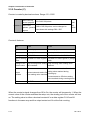
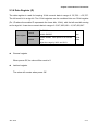
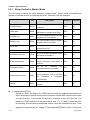
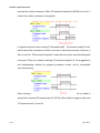
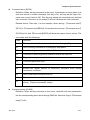
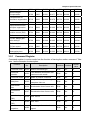
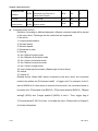
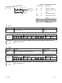
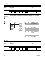
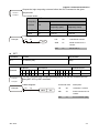
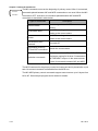
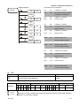
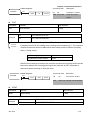
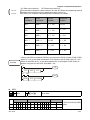
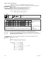
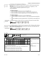
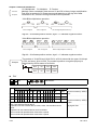
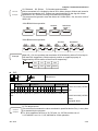
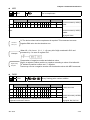
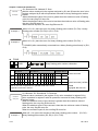
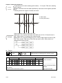
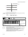
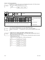
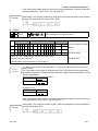
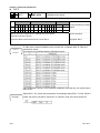
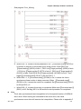
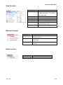
Chapter 2 Introduction of Controller 2.3.6 Data Register (D) The data register is used for keeping 16-bit numeric data in range of -32,768 ~ +32,767. The left most bit is a sign bit. Two 16-bit registers can be combined into one 32-bit register (D+1,D where the smaller ID represents the lower bits, 16-bit), with the left most bit serving as the sign bit. It can store numeric data in range of -2,147,483,648 ~ +2,147,483,647. General Data register D Latched D0~D2999 D4000~D65535 Total D3000~D3999, 1000 points is for latched 65536 zone. points Adjust the range by W12 and W13. General register When power Off, its value will be reset to 0. Latched register The value will remain when power Off. Jan. 2014 2-17 Chapter 2 Introduction of Controller 2.3.7 Indirect Reference Register (V) / (Z) Indirect reference register V is the 16-bit register and Z is the 32-bit one. Range is from V0~V127 to Z0~Z127. Each has 128 points. V is the 16-bit data register, which is the same as the 16-bit general ones. It can be written in or read without limit. If it is used as the general register, it only can be used in 32-bit 16-bit of command. Z is the 32-bit data register. If it is used as the general register, it only can be used in 32-bit of command. When X0 = On, V0 = 8, Z0 = 14, D5V0 = D(5+8) = D13, D10Z0 = D(10+14) = D24, and contents in D13 will be moved to D24. 2-18 Jan. 2014 Chapter 2 Introduction of Controller 2.3.8 Indicator (N) / Indicator (P) Indicator N For main control loop N0~N7, 8 points Main control loop’s control point P For CJ command Position indicator by using CJ P0~P255, 256 points Indicator N Work together with MC/MCR command. MC is the main control initial command. When MC command is active, commands between MC and MCR run in a normal manner. Indicator P Work together with application command CJ. Example: When X0 = On, the program jumps from address 0 to N (the assigned label P1), keeps executing and ignores statements in between. When X0 = Off, the program executes from address 0 downward Jan. 2014 and ignores command CJ. 2-19 Chapter 2 Introduction of Controller 2.3.9 Special Relay (R) / Special Register (W) Detailed descriptions are in the chapter of special devices. 2-20 Classification Range Special relay in PLC system R0 ~ R511 Special register in PLC system W0 ~ W511 Special relay in motion mode R512 ~ R1535 Special register in motion mode W512 ~ W4095 Jan. 2014 Chapter 2 Introduction of Controller 2.3.10 Constant (K) / Floating Points (F) Use 2 value types to execute computing. The following details the function of each one. The internal numerical computation adopts binary system, which is shown below. Bit Bit is the fundamental unit of a binary numeric value. It features only two states: 0 and 1. Nibble Composed of four consecutive bits (e.g. bit0~bit3) to express decimal numbers 0~15 or once place, hexadecimal numbers 0~F. Byte Composed of two consecutive nibbles (e.g. 8 bits, bit0~bit7) to express two places, hexadecimal numbers 00~FF. Word Composed of two consecutive bytes (e.g. 16-bit, bit0~bit15) to express four places, hexadecimal numbers 0000~FFFF. Double Composed of two consecutive words (e.g. 32-bit, bit0~bit31) to express eight places, Word hexadecimal number 00000000~FFFFFFFF. Constant K Decimal numbers are usually prefixed with the letter K, such as K100, represents a decimal constant of value 100. Exceptions: Constant K can be combined with bit devices X, Y, M to express data in nibble, byte, word or double word format. Take K2Y10 and K4M100 as the example. Here K1 represents a 4 bits combination; K2~K4 represents a combination of 8, 12 and 16 bits respectively. Constant F Operand in application command, e.g.【FADD F12.3 F0 D0】. (F represents a floating point constant.) Jan. 2014 2-21 Chapter 2 Introduction of Controller 2.4 Command List Followings are the commands provided by HMC controller. Basic Command Type Code Contact LD Symbol command LDI Type Code Timing TMR Counting CNT DCNT AND Combine ANI Program OR end ORI Timing command Subroutine SRET ORB OR B MPP Output OUT command SET MPS MRD MPP end Invert Rising Falling PLS No PLF operation control MCR NP edge edge MC INV phase RST Main IRET end A NB MRD END program ANB MPS Symbol PN NOP command Rising LDP and LDF falling ANDP edge ANDF detection ORP ORF 2-22 Jan. 2014 Chapter 2 Introduction of Controller Application Command Type API Command code 16-bit Function STEPS 32-bit Data 001 LD※ DLD※ Contact type compare 5 compare 002 AND※ DAND※ Contact type compare 5 003 OR※ DOR※ Contact type compare 5 Data 004 MOV DMOV Data move 5 transfer 005 BMOV - All sending 11 and 006 CML DCML Invert sending 5 compare 007 BCD DNCD BIN→BCD convert 5 008 BIN DBIN BCD→BIN convert 5 009 - FCMP Floating point compare 7 050 FMOV DFMOV Assign all 11 010 REF - I/O update 2 Rotate and 011 ROR DROR Right rotate 3 shift 012 ROL DROL Left rotate 3 Loop 013 CJ - Conditional jump 2 control 014 CALL - Call subroutines 2 Activate motion 2 I/O Page 015 LAUNCH - program 016 FOR - Nest loops start 3 017 NEXT - Nest loops end 1 Arithmetic 018 ADD DADD BIN addition 7 computing 019 SUB DSUB BIN subtraction 7 command 020 MUL DMUL BIN multiplication 7 021 DIV DDIV BIN division 7 022 INC DINC BIN add one 3 023 DEC DDEC BIN minus one 3 Logic 024 WAND DWAND AND operation 7 computing 025 WOR DWOR OR operation 7 command 026 WXOR DWXOR XOR operation 7 027 NEG DNEG Two’s complement 3 028 - FADD Floating point number 7 Floating addition points computing 029 - FSUB and convert Floating point number 7 subtraction 030 - FMUL Floating point number 7 multiplication Jan. 2014 2-23 Chapter 2 Introduction of Controller 031 - FDIV Floating point number 7 division 032 - FINT Floating point → 5 Integer 033 - FDOT Integer → Floating 5 point 034 FRAD Degree → Radian 5 035 FDEG Radian → Degree 5 036 FSIN Floating point SIN 5 operation 037 FCOS Floating point COS 5 operation 038 FTAN Floating point TAN 5 operation 039 FASIN Floating point ASIN 5 operation 040 FACOS Floating point ACOS 5 operation 041 FATAN Floating point ATAN 5 operation 042 FSQR Floating point square 5 root operation Data 043 ZRST - Zone reset 4 processing 044 DECO - Decoder 11 command 045 ENCO - Encoder 11 046 BON DBON Bit ON detect 5 047 ALT - ON/OFF alternation 2 048 RSVP - Read parameters from 13 Others servo drive 049 WSVP - Write parameters to 13 servo drive 051 CKFZ 2-24 Forbidden zone check 5 Jan. 2014 Chapter 3 Special Devices 3.1 List of Special Devices There are two types of special devices, special relay(R) and special register(W). For controller system and servo motion control, it can be classified as PLC system and motion mode. System’s motion control and monitoring function can be realized by special devices of HMC. Please note that the command of block move (e.g. BMOV command) cannot be executed by special devices. Type PLC special relay Range R0 ~ R511 Special relay in motion mode R512 ~ R1535 PLC special register W0 ~ W511 Special register in motion mode Jan. 2014 W512 ~ W4095 3-1 Chapter 3 Special Devices 3.2 PLC Special Relay This special relay can be used to acquire the system’s current status, including the calculating result, error monitoring, the connection of peripheral devices, key trigger and etc. Type Operation flag No. R0 Function Normally close Description Attribute Latched B contact R No A contact R No On means abnormal; Off R/W contact R1 Normally open contact R4 Error flag means normal R7 R8 Motion control reset Zero flag On means reset, and will Yes R/W be clear automatically No On means the calculation R No is 0. R9 Borrow flag On: the computing result R No R No R/W No R No R/W No R No R No R/W No is to borrow. R10 Carry flag On: the computing result is to carry R13 R14 Speed up data On means activate; Off exchange means deactivate Motion control ready On means ready; Off means not ready R15 Flag of error R16 Motion control On means activate; Off activate means deactivate Remote IO error On means it is unable to types establish connection; Off means the connection is established. R17 DMCNet On means it is unable to communication error establish connection; Off means the connection is established. R18 Grammar error On means grammar error occurs during the operation, which needs 3-2 Jan. 2014 Chapter 3 Special Devices to be cleared by users. R19 Motion control error On means motion control R No R/W No R/W Yes R/W Yes is abnormal; Off means normal. R20 Command error On means command error occurs during the operation, which should be cleared by users. Setting of R32 Setting of C200 On = count down, Off = counting mode count up Setting of C201 On = count down, Off = counting mode count up ~ ~ ~ ~ ~ R86 Setting of C254 On = count down, Off = R/W Yes counting mode count up Setting of C255 On = count down, Off = R/W Yes counting mode count up Connection status of On = online, Off = offline R No On = online, Off = offline R No 32-bit counting R33 mode R87 Remote IO R96 station 0 module connection R97 status Connection status of station 1 ~ ~ ~ ~ ~ R126 Connection status of On = online, Off = offline R No On = online, Off = offline R No station 30 R127 Connection status of station 31 PLC special R139 EMS button status On = press, Off = release R No flag R140 Limit switch status On = press, Off = release R No Normally close contact (R0) Definition: The flag is constantly On during operation. It is called normally close contact (B contact / NC). Normally open contact (R1) Definition: The flag is constantly Off during operation. It is called normally open contact (A contact / NC). Jan. 2014 3-3 Chapter 3 Special Devices Error flag (R4) Definition: One of the error flags is activated, this flag will be On. It should be cleared by users after the alarm is relieved. Related device: 【Remote I/O error】 (R16), 【DMCNet communication error】 (R17), 【Grammar error】(R18),【Motion control error】(R19) or 【Command error】 (R20) is activated so that this flag is ON. Motion control reset (R7) Definition: Set this flag On to reset system motion control. After it is done, the flag will be Off automatically. Zero flag (R8) Definition: After executing operational command, if the result is 0, this flag will be On. Borrow flag (R9) Definition: After executing 16-bit operational command, if the result is less than -32,768 or the result of 32-bit operation is less than -2,147,483,648, then this flag is ON. Carry flag (R10) Definition: After executing 16-bit operational command, if the result is more than 32,767 or the result of 32-bit operation is more than 2,147,483,647, then this flag is ON. Speed up data exchange (R13) Definition: On means the speed up function is done, and the system will arrange more time to deal with the communication between PLC and HMI. Therefore, the display of servo status on HMI will be timelier and the data exchange between PLC and HMI will be more quickly. While turning off this flag, this function will be disabled. Motion control ready (R14) Definition: Check if the node connection of DMCNet network is completed. On means the connection is done. 3-4 Jan. 2014 Chapter 3 Special Devices Motion control activate (R15) Definition: Check if the node underlying connection of DMCNet network is completed. On means the connection is completed. Set it to Off can reset the network. REMOTE IO error (R16) Definition: Check if the connection of Remote IO connected to HMC is normal. On means the connection is in error. Related device: The alarm code is shown in 【Error Code of Remote IO】(W16) when this flag is activated. This flag is off automatically when the connection is back to normal. DMCNET communication error (R17) Definition: Check if the connection of DMCNet is normal. On means the connection is in error. This flag is off automatically when the connection is back to normal. Related device: The alarm code is shown in【Error Code of DMCNet】(W17) when this flag is activated. Grammar error (R18) Definition: This flag is On when grammar error occurs during the command execution. Then, program scan is unable to carry on, jumps from the error occurred command and starts scan from the beginning. Users need to set this flag to off after the alarm is cleared. Related device: The alarm code is shown in【Grammar error code】(W18) when this flag is activated. Motion control error (R19) Definition: On means the system’s motion control is in error. 【Grammar Error Code】 needs to be activated to clear the error. Command error (R20) Definition: This flag is On when command error occurs during the operation. Program scan is unable to carry on. It will jump from the wrong command and start Jan. 2014 3-5 Chapter 3 Special Devices to scan from the beginning. Users need to set this flag to off after the alarm is cleared. Related device: The alarm code is shown in 【Command error code】(W20) when this flag is activated. Setting of C200~C255 counting mode flag (R32~R87) Definition: When flag is Off, the counter counts up while On means the counter counts down. REMOTE I/O connection status flag (R96~R127) Definition: When flag is On, it means the connection is normal while Off means it is disconnected. R96 is the 1st station’s connection status and R97 represents the second one and so on. EMS button status (R139) Definition: When flag is On, it means the EMS button is pressed. Off means it is released. Limit switch status (R140) Definition: When flag is On, it means the limit switch is in enabled status. Off means the switch is disabled. 3-6 Jan. 2014 Chapter 3 Special Devices 3.3 PLC Special Register This special register can acquire system’s status and the related settings, including the information of version and controller’s system, alarm code, peripheral devices and etc. Type No. Function Description Attribute Latched Information of W0 Module number DW R No controller W2 DSP Firmware DW R No DW R No system number W4 Program format version W7 Program size Unit: Step R No W8 Address of execution DW, Unit: Step R/W No The starting address Default value: 512. R/W Yes of latched device M The setting value R/W Yes Default value: 3000 R/W Yes Default value: 1000 R/W Yes R No error W10 should be 16’s multiple. W11 The size of latched Default value: 512. device M The setting value should be 16’s multiple. W12 The starting address of latched device D W13 The size of latched device D Alarm code W16 Remote I/O alarm code W17 DMCNet alarm code R No W18 Grammar error code R No W19 Motion control alarm R No R No R No ~ No R No code W20 Command error code Remote IO W32 number of station 0 module version number Module version ~ ~ W63 Module version ~ number of station 31 Jan. 2014 3-7 Chapter 3 Special Devices Information of W66 FPGA controller Others FPGA firmware R No R No version W67 FPGA PCB version W68 Time stamp DW, Unit: 0.1 ms R No W72 Retry times of Default value: 0 R/W Yes Default value: 0 R/W Yes R/W Yes R/W Yes R/W No command issuing W73 Retry times of servo parameter issuing W74 Handwheel factor W75 DMCNet Mask Command mask setting of each station in DMCNet. The default value is FFFF. It should be set to FCFF when using special ASDA-M 4-axis synchronized servo drive. W76 Handwheel counting DW, pulse counter of outer type of handwheel Module number (W0) Definition: Controller’s module number, which is in DW format. DSP firmware number (W2) Definition: Controller’s DSP firmware number, which is in DW format. CWP format version (W4) Definition: Controller’s program format version, which is in DW format. Program size (W7) Definition: Step number in controller’s program Address of execution error (W8) Definition: When command execution error occurs, the step address of program error will be reported. 3-8 Related device: It occurs with【Grammar error】(R18) or【Command error】(R20). Jan. 2014 Chapter 3 Special Devices The starting address of latched device M (W10) Definition: The setting of starting address of latched device M. Its setting value should be 16’s multiple. The size of latched device M (W11) Definition: The setting of the size of latched device M. Its setting value should be 16’s multiple. The starting address of latched device D (W12) Definition: The setting of starting address of latched device D. The size of latched device D (W13) Definition: The setting of the size of latched device D. REMOTE I/O error code (W16) Definition: Communication error code of Remote I/O The error code: A. 01: No Remote I/O device is detected B. 03: Detect the disconnection of Remote I/O device DMCNET error code (W17) Definition: Communication error code in DMCNet underlying network. The error code: A. 01: unable to initialize DMCNet hardware B. 02: unable to activate DMCNet hardware C. 03: unable to initialize DMCNet connection D. 04: underlying communication error on DMCNet E. 05: device connection error on DMCNet Related device: Activate with【Remote IO error】(R16) Related device: Activate with【DMCNet communication error】(R17) Grammar error code (W18) Definition: Grammar error code during operation. The error code: Code 05 Jan. 2014 Definition FOR ~NEXT loop depth exceeds 5 3-9 Chapter 3 Special Devices 06 CALL sub program depth exceeds 8 07 Floating point format is in error 10 The used device exceeds the range 11 RSVP, WSVP command execution error 12 The launched motion programs in queue that wait to be executed exceed 255 Related device: Activate with【Grammar error】(R18) Motion control error code (W19) Definition: Error occurs while processing motion control The error code: Code 09 3-10 Error occurs when processing motion command Related device: Activate with【Motion control error】(R19) Command error code (W20) Definition: Command error code during operation. The error code: Definition code Definition 01 The conversion of BCD command exceeds 0~9,999 or the conversion of DBCD command exceeds 0~99,999,999. 02 The devisor of DIV, DDI, FDIV command is 0 03 No bit is 1 in ENCO command source 04 The value exceeds 0~9 in BIN/DBIN command source 10 The source of FASIN command exceeds -1.0 ~ 1.0 11 The source of FACOS command exceeds -1.0 ~ 1.0 Related device: Activate with【Command error】(R20) REMOTE IO module version (W32~W63) Definition: Remote IO module version of each station Jan. 2014 Chapter 3 Special Devices FPGA firmware version (W66) Definition: FPGA firmware version of HMC FPGA PCB version (W67) Definition: FPGA PCB version number of HMC Time stamp (W68) Definition: Time stamp of the system. Unit: 0.1ms; in DW format Retry times of command issuing (W72) Definition: It is the setting of communication times when HMC issues command to servo. If the default value is 0, the system will issued each command twice to servo. Users could increase the time in order to enhance the communication quality. If the setting value is 3, then the command will be issued five times to servo. Retry times of servo parameter issuing (W73) Definition: It is the setting of communication times when HMC writes the special relay with Remote attribute into servo. If the default value is 0, the system will writes into servo twice. User can increase the time in order to make sure the accuracy of writing parameters. If the setting value is 3, then the parameter will be written into servo for 5 times. Handwheel factor (W74) Definition: The scaling setting of pulse received by handwheel and transferred to servo drive. Through this, handwheel pulse can be magnified in order to meet the requirement. For example, 100 pulses can be sent by operating the handwheel for a cycle. If the motor needs 1,280,000 pulses for running a cycle in ASDA-M, the scaling setting should be 12,800 (1,280,000 / 100 = 12,800). Then, if handwheel operates a cycle, the motor will run a cycle. Related device: Flag is enabled means the axis is controlled by handwheel. It might be axis 1 (R608), axis 2 (R609), …, or axis 12(R619). It only can enable one axis each time. If more than one axis is enabled, the alarm occurs. Its scaling setting will influence the accumulated counting of【Handwheel counting】(W76). Jan. 2014 3-11 Chapter 3 Special Devices DMCNET MASK (W75) Definition: It is the mask setting when controller communicates with DMCNet’s each station. With the general servo drive, the value should set to FFFF. However, the special framework should have different setting value, such as ASDA-M which supports 4-axis synchronized servo drive. The value should be set to FCFF to enable the operation. Handwheel counting (W76) Definition: It is the accumulated counting value which magnified the pulse number received by handwheel and then transferred to the servo drive. Related device: When the handwheel magnified the received pulse number through 【Handwheel factor】(W74),【Handwheel factor】(W76) will accumulate the magnification value. 3-12 Jan. 2014 Chapter 3 Special Devices 3.4 Special Relay in Motion Mode HMC controls servo for 12 axes at most in DMCNet. The corresponding axis of each axis is as the following: Corresponding address Function Axis 1 Axis 2 Axis 3 Axis 4 Axis 5 Axis 6 ~ Axis 12 Control by Servo axis Command start R512 R513 R514 R515 R516 R517 ~ R523 Quick stop R528 R529 R530 R531 R532 R533 ~ R539 Forward Jog R544 R545 R546 R547 R548 R549 ~ R555 Reverse Jog R560 R561 R562 R563 R564 R565 ~ R571 Servo On R576 R577 R578 R579 R580 R581 ~ R587 Fault Reset R592 R593 R594 R595 R596 R597 ~ R603 Handwheel ~ activate R608 R609 R610 R611 R612 R613 Command load R624 R625 R626 R627 R628 R629 ~ R635 Command cancel R640 R641 R642 R643 R644 R645 ~ R651 Feed rate R619 ~ execution R656 R657 R658 R659 R660 R661 R667 Pause R672 R673 R674 R675 R676 R677 ~ R683 Command error R1024 R1025 R1026 R1027 R1028 R1029 ~ R1035 Command ready R1040 R1041 R1042 R1043 R1044 R1045 ~ R1051 Servo axis Command ~ complete R1056 R1057 R1058 R1059 R1060 R1061 Servo ON R1072 R1073 R1074 R1075 R1076 R1077 Servo quick stop R1067 ~ R1083 ~ release R1088 R1089 R1090 R1091 R1092 R1093 Servo Fault R1104 R1105 R1106 R1107 R1108 R1109 ~ R1115 Servo Warning R1120 R1121 R1122 R1123 R1124 R1125 ~ R1131 Servo ready R1136 R1137 R1138 R1139 R1140 R1141 ~ R1147 Jan. 2014 R1099 3-13 Chapter 3 Special Devices 3.4.1 Relay Control in Motion Mode The list below is about the relay control in motion mode. These could accomplish the function to activate motion or clear the flag error. Take axis 1 as the example: Function No. Command start R512 Quick stop R528 Forward Jog R544 Reverse Jog R560 Servo On R576 Fault Reset R592 Handwheel activate R608 Description Attribute Latched R/W No R/W No R/W No R/W No R/W No R/W No R/W No motion command and starts to R/W No On is starting motion command execution On means servo quick stops while Off means to release quick stop On is for activating JOG in forward direction. Off is to release On is for activating JOG in reverse direction. Off is to release. On means Servo On while Off means Servo Off On means to clear the servo error On is to enable handwheel while Off means to disable it. On is to load in the continuous Command preload R624 execute. Command cancel R640 On is for cancelling the continuous motion command. R/W No R/W No R/W No On means to change the speed Feed Rate execution R656 during operation. It turns Off after the command is completed automatically. Pause R672 On means pause; Off means resume Command start (R512) Definition: When the flag is On. HMC starts to write the related parameters into servo and starts to execute the motion command. When HMC controls more than one servo drives, it only needs to issue the command to the very first one. For instance, if HMC controls a 5-axis servo drive, axis 1, 2, 3, 4 and 5, when the drive is executing 5-axis linear synchronized motion, issue the command to axis 1 and trigger the command will do. Trigger 【Command start】(R512) of axis 1 to On and 3-14 Jan. 2014 Chapter 3 Special Devices sets up【Command selection】 (Set W513 to 31. If Bit0 is On in W513, it means axis 1 should be activated, Bit1 On represents axis 2 and so on and so forth) to determine the related motion axis. If desire to execute 3-axis linear synchronized motion of axis 2, 3, and 4. Issue the command to axis 2 will do. Trigger 【Command start】(R513) of axis 2 to On and set up 【Command selection】can be done. (Set W769 to 7. Bit0 On means axis 2 should be activated, Bit1 On represents axis 3 and, Bit3 On represent s the fourth axis). Apart from linear motion of multi-axis, if desire to execute the arc or helical motion, issuing the command to the first axis of ASDA-M will do. In the following framework, HMC can only enable 【Command start】(R512) of axis 1 to execute arc or helical motion of axis 1, 2, and 3. Activate【Command start】 (R516) of axis 5 to execute arc or helical motion of axis 5, 6, and 7. Related device: Flag of【Command complete】 will have different status in different motion type. It is suggested to use handshaking method for program procedure control and to accomplish command issuing. Take axis 1 as the example, in homing, linear and jog motion, before activate the command, users should write in the motion command and its correct corresponding parameters. When the setting of 【 Command code 】 (W512), 【Command selection】(W513),【Speed setting】(W518),【Target position】(W520) is correctly completed, activate 【Command start】(R512). If the command has been written into the servo, the status of【Command ready】(R1040) is On. Then, Jan. 2014 3-15 Chapter 3 Special Devices execute the motion command. When【Command complete】(R1056) turns On, it means the motion command is completed. In speed command, when issuing【Command start】,【Command ready】is On, which means the command is issued to the servo drive and executed. However, it will not turn On 【Command complete】 when the servo drive executes the speed command. There is no need to wait flag,【Command complete】. It is suggested to use handshaking method for program procedure control and to accomplish command issuing. When issuing the command is in error or servo status error, which is unable to accept the command,【Command start】 (R512) will be failed to trigger motion and 【Command error】turns On. 3-16 Jan. 2014 Chapter 3 Special Devices Error: The following situations might result in【Command error】after activating 【Command start】. The corresponding error code will display in 【Error code】 (W576, ...) of each axis. Code Definition 01 The speed is set to 0 or becomes 0 after transferring by E-gear ratio. 02 Axis of issuing command is in emergency stop status 03 Axis of issuing command is in Servo Off status 04 Command is executing and is unable to receive the new one. 05 Trigger the wrong command selection 06 Command parameter error 07 Command code error 08 Exceed the largest amount of continuous command when issuing continuous command 09 Issue continuous command time out 10 Command code cannot be used in continuous motion 11 Wrong 【Speed command】setting Quick stop (R528) Definition: Flag【Quick stop】turns On. If the axis is in operation, it will stop the motion and then, stop urgently. Jan. 2014 3-17 Chapter 3 Special Devices Related device: Take axis 1 as the example, when 【Quick stop】(R528) is activated, if the servo is in operation, it will execute emergency stop according to 【Quick Stop deceleration time】(W670). Then, status of 【Servo quick stop release】(R1088) is Off, which means the axis is in the status of Quick stop. When 【Quick stop】(R528) is Off, status of 【Servo quick stop release】(R1088) will be On, which means the axis is not in quick stop status. Forward Jog (R544) Definition: Flag【Forward Jog】 is On. This axis is executing Jog in forward direction and will stop when the flag turns Off. Related device: Take axis 1 as the example, when【Forward Jog】 (R544) turns On, it will accelerate to the speed of【Jog speed】(W678) according to the curve of 【Jog acceleration time】(W680). Then, it will remain at constant speed in forward direction according to 【Jog speed】(W678). When 【Forward Jog】(R544) is Off, the axis will decelerate to stop according to the curve of 【Jog deceleration time】 (W681). In addition, set up 【Jog torque limit】(W682) can accomplish the torque protection function of Jog. 3-18 Jan. 2014 Chapter 3 Special Devices Error: The following situation might result in no action after enabling the flag. A. Servo is not in Servo On status. B. Jog speed (W678) exceeds the setting of maximum speed limit (W660). C. Servo is in Quick Stop status. D. Handwheel function is activated. E. Jog speed (W678) is set to 0. Reverse Jog (R560) Definition: Flag【Reverse Jog】 is On. This axis is executing Jog in reverse direction and will stop when the flag turns Off. Related device: Take axis 1 as the example, when【Reverse Jog】 (R560) turns On, it will accelerate to the speed of【Jog speed】(W678) according to the curve of 【Jog acceleration time】(W680). Then, it will remain at constant speed in reverse direction according to 【Jog speed】(W678). When 【Reverse Jog】(R560) is Off, the axis will decelerate to stop according to the curve of 【Jog deceleration time】 (W681). In addition, set up 【Jog torque limit】(W682) can accomplish the torque protection function of Jog. Jan. 2014 3-19 Chapter 3 Special Devices Error: The following situation might result in no action of servo after enabling the flag. A. Servo is not in Servo On status. B. Jog speed (W678) exceeds the setting of maximum speed limit (W660). C. Servo is in Quick Stop status. D. Handwheel function is activated. E. Jog speed (W678) is set to 0. SERVO ON (R576) Definition: Set flag 【Servo On】 to On. This axis is Servo On. If the flag is set to Off, then it is Servo Off. Related device: Take axis 1 as the example, when flag【Servo On】(R576) is On, this axis will be Servo On. Status in 【Servo On】(R1072) will be On. If flag 【Servo On】(R576) is Off, then the axis will be Servo Off and display Off status in 【Servo On】(R1072). 3-20 Error: The following situation might result in no action of servo after enabling the flag. A. DMCNet connection error. Check if it is DMCNet communication error (R17) or motion control error (R19). FAULT RESET (R592) Definition: When servo axis is in error, this flag is On and enables the servo to clear the error. Users have to self turn the flag Off. Jan. 2014 Chapter 3 Special Devices Handwheel activate (R608) Definition: Turn On the flag to activate the handwheel. Only one axis of handwheel can be activated at a time. Activate multi-axis of handwheel will cause command error. Related device: After enabling handwheel function, the controller will multiply the pulse number which sent by handwheel according to【Handwheel factor】(W74), then issue operation command to the servo. Error: The following situation might result in no action of servo after enabling the flag. A. Servo is not in Servo On status. B. Handwheel function from other axis had been activated. Command load (R624) Definition: 【 Command load 】 is the flag for loading in continuous motion commands and execution. It turns On the flag【Command load】, and HMC starts to write related parameters into servo (preload command). When the write-in is completed, HMC starts to execute continuous motion commands. Before the current command has been completed (At least two are executing), other motion command still can be loaded in. These commands will be wrote into the servo Jan. 2014 3-21 Chapter 3 Special Devices continuously and then executed in order so as to accomplish the so-called continuous motion commands. Multi-axis linear or arc motion can be issued to continuous commands, only by writing into different command code and parameters will do. Also, through the setting of 【Overlap】, function of PR overlap can be enabled. When two PR are executed overlap, the motion can be completed quickly and smoothly. The way of issuing each section of continuous motion command is the same as the single one. The difference is that single command should trigger 【Command start】(R512) and wait until 【Command complete】(R1056) is done so it can execute the next command. As for continuous command, triggering【Command load】(R624) can issue and execute the command. After enabling 【Command load】, wait till 【Command ready】(R1040) is On, which means the command had been successfully loaded into the servo. And then, users can issue the next command. When all issued commands are completed, 【Command complete】 (R1056) turns On. Please note that for continuous command, when the last one is executed, the new command cannot be loaded in. Related device: Take axis 1 as the example, when issuing continuous commands, please write in commands and parameters first, such as 【Command code】 (W512),【Command selection】(W513),【Speed setting】(W518),【Target position】 (W520) and【Parameter start address】(W525). Then, trigger 【Command load】 (R624) in order to write parameters into the servo. When the status of【Command ready】(R1040) is On, it means the command has been successfully written into the servo. When the second command is loaded in, the system will start to execute the motion. Before the last command has been executed, users can load in new command continuously. These load-in commands will be executed in order. 3-22 Jan. 2014 Chapter 3 Special Devices 【 Command complete 】 (R1056) turns On when all load-in commands are completed. The relevant Handshaking procedure is as the following: HMC can preload 8 motion commands at most. Through【PR surplus】(W594), users could acquire the remained number of commands which has been preloaded into the servo. When the number reached the limit 【PR ( surplus】(W594) equals 8), users will not be able to issue new【Command load】. Flag of 【Command ready】will not be On, which means the new motion command will be unable to write into the servo. Some current PR have to be completed, which means【PR surplus】(W594) should less than 8 so that the system could trigger new【Command load】and write into the servo. Jan. 2014 When the continuous command is being executed, if that is the last one (W594 = 1), then it could not receive new preload command. Users should wait until the current command is completed or stopped. If preload the wrong command, the preload command is failed and will not be wrote into the servo. Error: The following situation might result in command error. Code Definition 01 The speed is set to 0 or becomes 0 after transferring by E-gear ratio. 02 Axis of issuing command is in emergency stop status 03 Axis of issuing command is in Servo Off status 04 Command is executing and is unable to receive the new one. 05 Trigger the wrong command selection 06 Command parameter error 3-23 Chapter 3 Special Devices 07 Command code error 08 Exceed the largest amount of continuous command when issuing continuous command 09 Issue continuous command time out 10 Command code cannot be used in continuous motion 11 Wrong 【Speed command】setting Command cancel (R640) Definition: When executing continuous commands, after triggering【Command cancel】(R640), all preloaded continuous commands will be canceled and stop executing. Related device: Take axis 1 as the example, when executing continuous commands, if 【Command cancel】is On, command executing will stop and end the continuous commands. Then,【Command ready】(R1040) and【Command complete】(R1056) will be On. The relevant handshaking procedure is as the following: 3-24 Jan. 2014 Chapter 3 Special Devices FEED RATE execution (R656) Definition: During command execution, after triggering 【Feed Rate execution】, the setting of 【Feed Rate speed】, 【Feed Rate acceleration time】 and【Feed Rate deceleration time】will be changed. When the related commands of Feed Rate are executed, this flag will return to Off automatically. In continuous motions, change the Feed Rate will only change the current motion. Before the current command is completed, it will execute the command according to the original setting speed. That is to say, change the feed rate is only effective to the current motion command. Related device: Take axis 1 as the example, if 【Feed Rate execution】(R656) is On, the motion speed will be changed to【Feed Rate speed】(W684), the acceleration time will be changed to 【Feed Rate acceleration time】(W686) and the deceleration time will be【Feed Rate deceleration time】(W687). After the change is completed, flag【Feed Rate execution】(R656) is Off automatically. Meanwhile, this will not influence the time sequence of command issuing. Pause (R672) Definition: Set 【Pause】to On during operation, the current action will stop. Set it to Off when the operation stops so that it will resume the original operation. Jan. 2014 3-25 Chapter 3 Special Devices 3.4.2 Status Relay in Motion Mode Status relay in motion mode indicates servo’s current alarm and function. The following is described in axis 1. Function Command error No. R1024 Description On means it is in error when Attribute Latched R/W No R No R No R No R No issuing command. Users should self clear the error. Command ready R1040 On means the command has been issued to the servo. Command complete R1056 On means the servo has completed the command. Servo ON R1072 On means it is in Servo On status. Servo quick stop R1088 release On means servo quick stop has been released. Off means the servo is in quick stop status. Servo Fault R1104 On means servo error occurs R No Servo Warning R1120 On means servo alarm warning R No R No occurs Servo ready R1136 On means the connection between DMCNet and servo drive is established. 3-26 Jan. 2014 Chapter 3 Special Devices Command error (R1024) Definition: When issuing command to the servo, if parameter or servo status is in error and results in invalid command, this flag is On. As long as the flag is On, users have to set it back to Off. This flag only shows the command error that had ever occurred, if the error is not cleared, it will not influence the next command. Related device: Take axis 1 as the example, when issuing 【Command start】 (R512) or 【Command load】(R624), if command error occurs, 【Command error】 (R1024) is On. And 【Error code】(W576) will show the reason of error occurs. The error code is as the followings: Code Definition 01 The speed is set to 0 or becomes 0 after transferring by E-gear ratio. 02 Axis of issuing command is in emergency stop status 03 Axis of issuing command is in Servo Off status 04 Command is executing and is unable to receive the new one. 05 Trigger the wrong command selection 06 Command parameter error 07 Command code error 08 Exceed the largest amount of continuous command when issuing continuous command 09 Issue continuous command time out 10 Command code cannot be used in continuous motion 11 Wrong 【Speed command】setting Command ready (R1040) Definition: When issuing command to the servo, controller will write parameters into the corresponding servo drive through DMCNet. After that, flag of【Command ready】is On. Jan. 2014 3-27 Chapter 3 Special Devices If command error occurs, it means the command issuing is failed. Then, flag of 【Command ready】will not On. 【Command ready】is the vital one to issue the command. Related device: Take axis 1 as the example, when 【Command start】(R512) is On, 【Command ready】(R1040)] is Off automatically. When【Command start】(R512) is Off, 【Command ready】(R1040) is Off, too. Please refer to 【Command start】 in【Control relay in motion mode】for detailed time sequence description. Command complete (R1056) Definition: After issuing the command to servo drive,【Command complete】will be Off first. When the command is completed, 【Command complete】will be On. Related device: Take axis 1 as the example, when【Command start】(R512) is set to On,【Command complete】(R1056) of axis 1 is Off automatically. Please refer to 【Command start】 in 【Control relay in motion mode】for detailed time sequence description. Servo ON (R1072) Definition: It represents the servo drive’s status. When this flag is On, it means the axis is in Servo On status. When this flag is Off, it means the axis is Servo Off. Related device: Take axis 1 as the example, when【Servo On】(R576) is On, it means Servo On is activated. When the status of servo axis 1 becomes Servo On, 【Servo ON】(R1072) will be On. Servo quick stop release (R1088) Definition: See if servo axis is in quick stop status. If this flag is On, it means Quick Stop status has been released and can receive motion command. However, if this flag is Off, it means this axis is still in Quick Stop status and cannot receive motion command. 3-28 Related device: Take axis 1 as the example, if 【Quick stop】(R528) is On, it means HMC issues quick stop command to the servo. When servo is in quick stop status, flag of【Servo quick stop release】(R1088) is Off. Jan. 2014 Chapter 3 Special Devices Set【Quick stop】(R528) to Off, means HMC issues quick stop released command to the servo. If it is released successfully, flag of 【Servo quick stop release】 (R1088) is On. In addition, if【DI Function Planning】 of ASDA Servo parameter is set to Emergency stop (EMGS), DI signal will control the servo to be in quick stop status and HMC will lose its control. Servo fault (R1104) Definition: This flag will be On if an alarm occurs in servo axis. After being cleared, this flag is Off. Related device: Take axis 1 as the example, 【Servo alarm code】(W585) can show the alarm content of servo axis. 【Fault Reset】(R592) (Set to On) can be used to clear the alarm and reset the servo. Servo warning (R1120) Definition: When a warning occurs, this flag is On. When the warning is cleared, then this flag is Off. Related device: Take axis 1 as the example, 【Servo alarm code】(W585) can show the content of servo warning and【Fault Reset】(R592) (Set to On) can be used to clear the alarm and reset the servo. Servo ready (R1136) Definition: When DMCNet connection between HMC and the servo is completed, the corresponding servo axis will set this flag to On, which means successful connection. Jan. 2014 3-29 Chapter 3 Special Devices 3.5 Special Register in Motion Mode Latched, readable (R) and writable (W) are included in the attribute of【Special register in motion mode】. When the attribute of 【Latched】and【Remote】 are both in special register, its parameters’ setting value will be written into the servo drive when DMCNet connection between HMC and servo drive is successfully built. Take 【 Electronic gear ratio (Numerator/Denominator) 】 as the example, when HMC successfully connects to servo drive, the setting value of【Electronic gear ratio (Numerator)】 (W640) and 【Electronic gear ratio (Denominator)】(W642) will be wrote into P1-44 (GR1) and P1-45 (GR2) of the servo drive. Thus, through the parameter setting, HMC could keep the consistency of the system’s parameters. HMC can control 12 axes of servo axis at most. Its function and corresponding address of DMCNet each axis are as the followings: Corresponding address Function Axis 1 Axis 2 Axis 3 Axis 4 Axis 5 Axis 6 ~ Axis 12 Command Command code W512 W768 W1024 W1280 W1536 W1792 ~ W3328 Command selection W513 W769 W1025 W1281 W1537 W1793 ~ W3329 Command mode W514 W770 W1026 W1282 W1538 W1794 ~ W3330 Delay time W515 W771 W1027 W1283 W1539 W1795 ~ W3331 Acceleration time W516 W772 W1028 W1284 W1540 W1796 ~ W3332 Deceleration time W517 W773 W1029 W1285 W1541 W1797 ~ W3333 Speed setting (DW) W518 W774 W1030 W1286 W1542 W1798 ~ W3334 Target position (DW) W520 W776 W1032 W1288 W1544 W1800 ~ W3336 Speed proportion W522 W778 W1034 W1290 W1546 W1802 ~ W3338 address W524 W780 W1036 W1292 W1548 W1804 ~ W3340 Overlap W525 W781 W1037 W1293 W1549 W1805 ~ W3341 Speed option W526 W782 W1038 W1294 W1550 W1806 ~ W3342 Error code W576 W832 W1088 W1344 W1600 W1856 ~ W3392 Current position (DW) W578 W834 W1090 W1346 W1602 W1858 ~ W3394 Average torque (DW) W580 W836 W1092 W1348 W1604 W1860 ~ W3396 Current speed (DW) W582 W838 W1094 W1350 W1606 W1862 ~ W3398 Servo alarm code W585 W841 W1097 W1353 W1609 W1865 ~ W3401 Parameter start Status 3-30 Jan. 2014 Chapter 3 Special Devices Monitoring item 1(DW) W586 W842 W1098 W1354 W1610 W1866 ~ W3402 Monitoring item 2 (DW) W588 W844 W1100 W1356 W1612 W1868 ~ W3404 Monitoring item 3 (DW) W590 W846 W1102 W1358 W1614 W1870 ~ W3406 Monitoring item 4 (DW) W592 W848 W1104 W1360 W1616 W1872 ~ W3408 Motion surplus W594 W850 W1106 W1362 W1618 W1874 ~ W3410 W596 W852 W1108 W1364 W1620 W1876 ~ W3412 rate W598 W854 W1110 W1366 W1622 W1878 ~ W3414 Rapid monitoring item W600 W856 W1112 W1368 W1624 W1880 ~ W3416 Current speed W602 W858 W1114 W1370 W1626 W1882 ~ W3418 W640 W896 W1152 W1408 W1664 W1920 ~ W3456 (Denominator) (DW) W642 W898 W1154 W1410 W1666 W1922 ~ W3458 Unit display W644 W900 W1156 W1412 W1668 W1924 ~ W3460 Acc. / Dec. curve W645 W901 W1157 W1413 W1669 W1925 ~ W3461 Acceleration time W646 W902 W1158 W1414 W1670 W1926 ~ W3462 Deceleration time W647 W903 W1159 W1415 W1671 W1927 ~ W3463 Homing speed 1(DW) W648 W904 W1160 W1416 W1672 W1928 ~ W3464 Homing speed 2(DW) W650 W906 W1162 W1418 W1674 W1930 ~ W3466 Homing mode W652 W908 W1164 W1420 W1676 W1932 ~ W3468 Homing acc. /dec. time W653 W909 W1165 W1421 W1677 W1933 ~ W3469 W654 W910 W1166 W1422 W1678 W1934 ~ W3470 W656 W912 W1168 W1424 W1680 W1936 ~ W3472 W658 W914 W1170 W1426 W1682 W1938 ~ W3474 W660 W916 W1172 W1428 W1684 W1940 ~ W3476 Monitoring item index 1 W666 W922 W1178 W1434 W1690 W1946 ~ W3482 Monitoring item index 2 W667 W923 W1179 W1435 W1691 W1947 ~ W3483 Monitoring item index 3 W668 W924 W1180 W1436 W1692 W1948 ~ W3484 Monitoring item index 4 W669 W925 W1181 W1437 W1693 W1949 ~ W3485 DMCNet communication A error rate DMCNet communication B error Motion parameter Electronic gear ratio (Numerator) (DW) Electronic gear ratio Homing offset value (DW) Forward software limit (DW) Reverse software limit (DW) Maximum speed limit (DW) Jan. 2014 3-31 Chapter 3 Special Devices Quick Stop deceleration time W670 W926 W1182 W1438 W1694 W1950 ~ W3486 W671 W927 W1183 W1439 W1695 W1951 ~ W3487 W672 W928 W1184 W1440 W1696 W1952 ~ W3488 W673 W929 W1185 W1441 W1697 W1953 ~ W3489 W674 W930 W1186 W1442 W1698 W1954 ~ W3490 W675 W931 W1187 W1443 W1699 W1955 ~ W3491 W676 W932 W1188 W1444 W1700 W1956 ~ W3492 forward hardware limit W677 W933 W1189 W1445 W1701 W1957 ~ W3493 Jog speed (DW) W678 W934 W1190 W1446 W1702 W1958 ~ W3494 Jog acceleration time W680 W936 W1192 W1448 W1704 W1960 ~ W3496 Jog deceleration time W681 W937 W1193 W1449 W1705 W1961 ~ W3497 Jog torque limit W682 W938 W1194 W1450 W1706 W1962 ~ W3498 Feed Rate speed (DW) W684 W940 W1196 W1452 W1708 W1964 ~ W3500 W686 W942 W1198 W1454 W1710 W1966 ~ W3502 W687 W943 W1199 W1455 W1711 W1967 ~ W3503 index W688 W944 W1200 W1456 W1712 W1968 ~ W3504 Maximum speed limit W689 W945 W1201 W1457 W1713 W1969 ~ W3505 W704 W960 W1216 W1472 W1728 W1984 ~ W3520 W705 W961 W1217 W1473 W1729 W1985 ~ W3521 W706 W962 W1218 W1474 W1730 W1986 ~ W3522 W707 W963 W1219 W1475 W1731 W1987 ~ W3523 Deceleration time of stop command Deceleration time for communication error Motor overload deceleration time Deceleration time of reverse software limit Deceleration time of forward software limit Deceleration time of reverse hardware limit Deceleration time of Feed Rate acceleration time Feed Rate deceleration time Rapid monitoring item Servo parameter Auto low-frequency vibration suppression setting Inertia ratio to servo drive Proportional gain of position control Feed forward gain of position control 3-32 Jan. 2014 Chapter 3 Special Devices Speed control gain W708 W964 W1220 W1476 W1732 W1988 ~ W3524 W709 W965 W1221 W1477 W1733 W1989 ~ W3525 resonance suppression W710 W966 W1222 W1478 W1734 W1990 ~ W3526 Anti-interference gain W711 W967 W1223 W1479 W1735 W1991 ~ W3527 W712 W968 W1224 W1480 W1736 W1992 ~ W3528 position control (DW) W724 W980 W1236 W1492 W1748 W2004 ~ W3540 E-Cam curve scaling W726 W982 W1238 W1494 W1750 W2006 ~ W3542 W728 W984 W1240 W1496 W1752 W2008 ~ W3544 W730 W986 W1242 W1498 W1754 W2010 ~ W3546 W732 W988 W1244 W1500 W1756 W2012 ~ W3548 Speed integral compensation Low-pass filter of Speed detection filter and jitter suppression Excessive deviation of E-Cam: Master gear ratio setting P E-Cam: Activate E-Cam control E-Cam: Information of disengaging time 3.5.1 Command Register Command register in motion mode has the function of issuing the motion command. Take axis 1 as the example for description: Function Command code Command selection No. W512 W513 Command mode W514 Delay time W515 Acceleration time Deceleration time Speed setting (DW) Target position (DW) Speed proportion Jan. 2014 Description Motion command type The additional information that command code needs Mode of position command Delay time when positioning complete. Unit: ms Default Attribute Latched R/W No 0 R/W No 0 R/W No 0 R/W No 0 value W516 Acceleration time of servo axis R/W No 0 W517 Deceleration time of servo axis R/W No 0 W518 Unit: PUU/s R/W No 0 W520 Unit: PUU R/W No 0 R/W No 0 W522 Percentage of actual motion speed 3-33 Chapter 3 Special Devices Parameter start address Overlap The start address of accessing W524 parameters in D device in No 0 R/W No 0 R/W No 0 continuous PR path W525 PR overlap Additional information that linear Speed option R/W W526 motion needs Command code (W512) Definition: According to different demands, different command code will be issued to the servo drive. Followings are the codes that are supported. 0: No action 1: Linear synchronization 4: Forward speed 5: Reverse speed 6: Decelerate to stop 8: Homing 10: Arc: Radius & angle mode 11: Arc: Midpoint & end point mode 12: Arc: Center & end point mode 13: Arc: Radius & end point mode 14: Arc: Center & angle mode 24: 4-axis linear synchronization (Special type of servo drive) 30: Helical 31: Helical W Related device: When HMC issues command to the servo drive, the command needs to be written into【Command code】 of trigger axis. For example, for the 3 axes of ASDA-M, if users desire to execute 3-axis motion, the command needs to be written into 【Command code】(W512),【Command selection】(W513),【Speed setting】(W518) and 【target position】(W520) of axis 1. Then, trigger flag of 【Command start】(R512) of axis 1 to enable the servo. Please refer to Chapter 5 for further information. 3-34 Jan. 2014 Chapter 3 Special Devices Command selection (W513) Definition: Different【Command code】has different corresponding setting method of 【Command selection】, which needs to be written into the trigger axis. In linear and speed motion,【Command selection】is for enabling the axis, which starts from low bit to high bit in sequence. It will trigger the very first one. For example, when triggering 【 Command start 】 (R512) of axis 1, if bit0 of 【Command selection】(W513) is On, it means axis 1 needs to be activated. If bit1 is On, it means axis 2 needs to be activated and so on. However, when triggering 【Command start】 (R514) of axis 3, if bit0 of 【Command selection】 (W1025) is On, it means axis 3 needs to be activated. And if bit1 is On, it means axis 4 needs to be activated. 【Command selection】 is the axis selection for arc motion. If the 3-axis of ASDA-M is axis1, axis 2 and axis 3 in sequence, then 0 means the arc motion is executed in axis 1 and 2. 1 means it is executed in axis 2 and 3 and 2 means the motion is executed in axis 1 and 3. In helical motion, 【Command selection】is the axis selection for helical moving. If the 3-axis of ASDA-M is axis 1, axis 2 and axis 3 in sequence, then 0 means arc moving is executed in axis 1 and 2 and axis 3 is for helical height moving. 1 means arc moving is executed in axis 2 and 3 and axis 1 is for helical height moving. 2 means axis 1 and 3 is for arc moving and axis 2 is for helical height moving. Related device: If the motion axis includes axis 1, it needs to trigger 【Command start】(R512). And parameters it uses will be 【Command code】 (W512), 【Command selection】(W513) and the related ones such as speed, position and etc. Please refer to Chapter 5 for further information. Jan. 2014 3-35 Chapter 3 Special Devices Command mode (W514) Definition: The command mode used by linear motion supports the followings: 0: Absolute position command. The destination of position command is directly specified as DATA. 1: Relative position command. The destination of position command is the current feedback position plus the specified incremental DATA. 2: Incremental position command. The destination of position command is the previous command destination plus the specified incremental DATA. DELAY time (W515) Definition: The setting of Delay time after the single motion reaches the position. Acceleration time (W516) Definition: The setting of acceleration time in single motion. If there is no setting, please refer to the system’s【Acceleration time】(W646). Deceleration time (W517) Definition: The setting of deceleration time in single motion. If there is no setting, please refer to the system’s【Deceleration time】(W647). Speed setting (W518) Definition: In multi-axial synchronized motion, since the multi-axis has to be activated and ended simultaneously, the actual speed should be adjusted by the speed setting and moving distance of each axis. The default setting is based on the speed of the longest traveling distance. The speed of the axes with shorter travel distance will be adjusted by the based speed in order to synchronize multi-axis. Fault: Take axis 1 as the example, if the speed is set to 0, error will occur and 【Command error】(R1024) will be On. If the speed setting exceeds the setting value of 【Max. speed limit】 (W660), the system will operate at the speed of 【Max. speed limit】. In multi-axis synchronized motion, if one of the axes exceeds the speed of【Max. speed limit】, that axis will operate at【Max. speed limit】. Thus, 3-36 Jan. 2014 Chapter 3 Special Devices the speed of multi-axis synchronized motion will be limited by【Max. speed limit】 of each axis and reduce its speed. Target position (W520) Definition: Setting of command arrival position Related device: The target position will be influenced by 【Command mode】 (W514). The target position will be different because of the absolute, relative or incremental mode. Speed proportion (W522) Definition: The actual speed is the result of 【Speed setting 】multiplies the percentage of【Speed proportion】. If 【Speed setting】is 10000 and speed proportion is set to 20, then, the actual speed will be 10000 x 20% = 2000. Also, each axis influences the speed of all synchronized axis by the speed of triggering axis. The setting value is between 1 and 100. When exceeding the range, the setting of speed proportion will be regarded as 100, which operates at the speed of 【Speed setting】. Parameter start address (W524) Definition: When issuing arc and helical commands, the related parameters should be written into the continuous D register.【Parameter start address】is the start address of setting PR. Take axis 1 as the example, if【Parameter start address】 (W524) is set to 1000, then, when issuing commands, the system will start to capture data from D1000 and send it to servo. Take axis 1 in Arc: Radius & angle mode (Command code is 10) as the example, if【Parameter start address】(W524) is set to 1000, when issuing arc motion command, the system will issue parameters, which start from D1000 to the servo drive. Since the parameter needs 6 continuous bits, the 6 continuous bits should Jan. 2014 3-37 Chapter 3 Special Devices be reserved. For example, if W524 is set to 1000, when planning the program, D1000 ~ D1005 should be reserved. Assume that 【Parameter start address】is set to n, when executing arc motion, the definition of D register data is as the followings: Definition Parameter address Radius (DW) Dn Start angle (DW; Unit: 0.5°) Dn+2 Motion angle (DW; Unit: 0.5°) Dn+4 Take axis 1 in Arc: Midpoint & endpoint mode (Command code is 11) as the example, if 【Parameter start address】(W524) is set to 1000, when issuing motion command, the system will issue parameters, which start from D1000 to the servo drive. Since the parameter needs 8 continuous bits, the 8 continuous bits should be reserved. For example, if W524 is set to 1000, when planning the program, D1000 ~ D1007 should be reserved. Assume that 【Parameter start address】is set to n, when executing arc motion, the definition of D register data is as the followings: Definition Parameter address Midpoint coordinate 1 (DW) Dn Midpoint coordinate 2 (DW) Dn+2 Endpoint coordinate 1 (DW) Dn+4 Endpoint coordinate 2 (DW) Dn+6 Take axis 1 in Arc: Center & endpoint mode (Command code is 12) as the example, if 【Parameter start address】(W524) is set to 1000, when issuing motion command, the system will issue parameters, which start from D1000 to the servo drive. Since the parameter needs 10 continuous bits, the 10 continuous bits should be reserved. For example, if W524 is set to 1000, when planning the program, D1000 ~ D1009 should be reserved. Assume that【Parameter start address】is set to n, when executing arc motion, the definition of D register data is as the followings: 3-38 Jan. 2014 Chapter 3 Special Devices Definition Parameter address Circle center coordinate 1 (DW) Dn Circle center coordinate 2 (DW) Dn+2 Endpoint coordinate 1 (DW) Dn+4 Endpoint coordinate 2 (DW) Dn+6 Forward & reverse (DW, 0 forward, 1reverse) Dn+8 Take axis 1 in Arc: Endpoint & radius mode (Command code is 13) as the example, if 【Parameter start address】(W524) is set to 1000, when issuing motion command, the system will issue parameters, which start from D1000 to the servo drive. Since the parameter needs 8 continuous bits, the 8 continuous bits should be reserved. For example, if W524 is set to 1000, when planning the program, D1000 ~ D1007 should be reserved. Assume that【Parameter start address】is set to n, when executing arc motion, the definition of D register data is as the followings: Definition Parameter address Endpoint coordinate 1 (DW) Dn Endpoint coordinate 2 (DW) Dn+2 Radius (DW) Dn+4 Forward & reverse (DW, 0 forward, 1reverse) Dn+6 Take axis 1 in Arc: Center & angle mode (Command code is 14) as the example, if 【Parameter start address】(W524) is set to 1000, when issuing motion command, the system will issue parameters, which start from D1000 to the servo drive. Since the parameter needs 6 continuous bits, the 6 continuous bits should be reserved. For example, if W524 is set to 1000, when planning the program, D1000 ~ D1005 should be reserved. Assume that【Parameter start address】is set to n, when executing arc motion, the definition of D register data is as the followings: Jan. 2014 3-39 Chapter 3 Special Devices Definition Parameter address Circle center coordinate 1 (DW) Dn Circle center coordinate 2 (DW) Dn+2 Motion angle (DW; Unit: 0.5°) Dn+4 Take axis 1 in helical command (Command code is 30) as the example, if 【Parameter start address】(W524) is set to 1000, when issuing helical command, the system will issue parameters, which start from D1000 to the servo drive. Since the parameter needs 8 continuous bits, the 8 continuous bits should be reserved. For example, if W524 is set to 1000, when planning the program, D1000 ~ D1007 should be reserved. Assume that【Parameter start address】is set to n, when executing arc motion, the definition of D register data is as the followings: Definition Parameter address Radius (DW) Dn Start angle (DW; Unit: 0.5°) Dn+2 Motion angle (DW; Unit: 0.5°) Dn+4 Height (DW) Dn+6 Take axis 1 in helical W command (Command code is 31) as the example, if 【Parameter start address】(W524) is set to 1000, when issuing helical W command, the system will issue parameters, which start from D1000 to the servo drive. Since the parameter needs 10 continuous bits, the 10 continuous bits should be reserved. For example, if W524 is set to 1000, when planning the program, D1000 ~ D1009 should be reserved. Assume that【Parameter start address】is set to n, when executing arc motion, the definition of D register data is as the followings: Definition Parameter address 3-40 Circle center coordinate 1 (DW) Dn Circle center coordinate 2 (DW) Dn+2 Height of one cycle (DW) Dn+4 Jan. 2014 Chapter 3 Special Devices Total pitch number (DW) Dn+6 Offset angle (DW; Unit: 0.5°) Dn+8 Related device: Take axis 1 in arc motion as the example, set up arc command in 【Command code】(W512) and setup axis selection in 【Command selection】 (W513). Then trigger the flag of【Command start】(R512) to start the execution. HMC will access arc motion data from D register of【Parameter start address】 (W524) and then issue parameters to the servo drive. OVERLAP (W525) Definition: When executing the continuous motion,【Overlap】is for setting the overlap extent between the current motion and the next one. This setting could help to accomplish the interpolation between two paths. There are two ways for overlap: 1. Overlap for acceleration / deceleration time It is the overlap percentage of the current PR deceleration time and the next PR acceleration time. Parameter P1-78,【The setting of PR overlap】 (P1-78) should set to 0, the range of【Overlap】setting value and its definition are as the followings: Grade 7 Percentage 45% Grade F Percentage 100% 6 5 4 3 2 1 0 40% 35% 30% 25% 20% 10% 0% E D C B A 9 8 90% 80% 75% 70% 65% 55% 50% 2. Overlap for PR distance It is the percentage of the current and next PR distance. Parameter P1-78, 【The setting of PR overlap】(P1-78) should set to 1, the range of 【Overlap】setting value and its definition are as the followings: Jan. 2014 Index 0~F Description 0 1% 1 2% 3-41 Chapter 3 Special Devices 2 4% 3 6% 4 8% 5 10% 6 12% 7 14% 8 16% 9 18% A 20% B Refer to P1-79, The setting of the percentage of overlap PR path C Refer to P1-80, The setting of the distance of overlap PR path D Reserved E Reserved F Reserved The setting range of parameter P1-79 is 1 ~ 30. The setting unit of parameter P1-80 is PUU and the range is 100 ~ 2147483647. Related device: When executing continuous motion, take axis 1 as the example, when using【Command load】(R624) to load and trigger command, it will issue the command,【Overlap】to the servo drive so as to setup the interpolation between two PR paths. Speed option (W526) Definition: Through the setting of【speed option】, the speed type of linear motion can be changed. Refer to the followings for its setting. 1. 0: The longest traveling distance 2. 1 ~ 12: Speed of specified axis. The setting value means the multi-axis linear motion should be adjusted according to the speed of specified axis. For example, in three-axis linear motion (including axis 1, 2 and 3), if the setting value is 2, speed of axis 1 and 3 should be adjusted according to the speed setting of axis 2 (W774) so as to accomplish 3-axis linear synchronization. 3. 255: Vector speed; when regarding【Speed setting】of trigger axis as the vector speed of multi-axis linear motion, in 3-axis linear motion (axis 1, 2 and 3), if the setting value is 255, it means the speed (W518) of trigger axis is regarded as the vector speed during operation. 3-42 Jan. 2014 Chapter 3 Special Devices Related device: When executing multi-axis linear motion command, including axis 1, users should set 【Command code】(W512) of axis 1 to 1 (linear) and 【Command selection】(W513) as the related selection of motion axis, such as 【Speed setting】(W518, W774, W1030, ...) and【Target position】(W520, W776, W1032, ...). Refer to 【Speed option】(W526) so as to determine the speed mode. Then, trigger【Command start】(R512) of axis 1 will do. 3.5.2 Status Register It shows the current servo alarm status and servo function. Take axis 1 as the example: Function Error code Current position (DW) No. W576 W578 Average torque (DW) W580 Current speed (DW) W582 Servo alarm code W585 Monitoring item 1 (DW) Monitoring item 2 (DW) Monitoring item 3 (DW) Monitoring item 4 (DW) PR surplus W586 W588 W590 W592 W594 Description Latched R No 0 R No 0 R No 0 R No 0 R No 0 R No 0 R No 0 R No 0 R No 0 R No 0 DMCNet R No 0 Error code when failed to issue the command. Current servo drive’s position; Unit is PUU. Current servo drive’s average torque; Unit is %. Current servo drive’s speed; Unit is PUU/s. Servo alarm code, in BCD format The specified servo information of monitoring item 1 The specified servo information of monitoring item 2 The specified servo information of monitoring item 3 The specified servo information of monitoring item 4 The current written PR number in the servo drive. DMCNet Communication error rate in communication error W596 channel A (DW) communication Jan. 2014 A of Default Attribute value 3-43 Chapter 3 Special Devices DMCNet Communication error rate in communication error W598 channel B (DW) communication Rapid monitoring item (DW) Current speed W600 W602 B of DMCNet R The specified servo information of rapid monitoring item Current servo drive’s speed; Unit is RPM No 0 R No 0 R No 0 Error code (W576) Definition: When command issuing is failed, the error occurs with【Command error】, and it will display the current error code, which shown below: Code Definition 01 The speed is set to 0 or becomes 0 after transferring by E-gear ratio. 02 Axis of issuing command is in emergency stop status 03 Axis of issuing command is in Servo Off status 04 Command is executing and is unable to receive the new one. 05 Trigger the wrong command selection 06 Command parameter error 07 Command code error 08 Exceed the largest amount of continuous command when issuing continuous command 09 Issue continuous command time out 10 Command code cannot be used in continuous motion 11 Wrong 【Speed command】setting Current position (W578) Definition: The current position; Unit is PUU Average torque (W580) Definition: The current average torque; Unit is %. 3-44 Jan. 2014 Chapter 3 Special Devices Current speed (W582) Definition: The current speed; Unit is PUU/s. Servo alarm code (W585) Definition: The code shows when servo error occurs, and the code is in BCD format. Please refer to servo drive’s user manual for code definition. Monitoring item 1/2/3/4 (W586/W588/W590/W592) Definition: The status monitoring register which corresponds to the servo drive. Related device: 【Monitoring item index】determines the content of 【Monitoring item】. Take axis 1 as the example,【Monitoring item 1】(W586) will change its content according to【Monitoring item index 1】(W666). When changing the setting of 【Monitoring item index】, HMC will change the setting value and then send it to servo drive. Thus, the corresponding【Monitoring item】will display the correct parameter content after 1ms. PR surplus (W594) Definition: It represents the command number that has been written into the servo drive and waits for execution. HMC can preload 8 commands into the servo drive at most. Range is from 0 to 8. 0 means no command is executing. In continuous command, when【PR surplus】is 8, it means the system has already been preloaded 8 commands and cannot trigger【Command load】(R624) at the moment. That is to say, flag of【Command ready】(R1040) will not be On until the current command is completed . When the number of【PR surplus】is less than 8, the new command can be loaded into the servo drive and flag of 【Command ready】 (R1040) will be On. Jan. 2014 3-45 Chapter 3 Special Devices DMCNet communication error A/B (W596/W598) Definition: The cumulative number of lost packages on communication channel A/B of DMCNet. Rapid monitoring item (W600) Definition: The rapid monitoring register which corresponds to the servo drive. Related device: 【Rapid monitoring item index】(W688) determines the content of 【Rapid monitoring item】(W600). When changing the setting of 【Rapid monitoring item index】, HMC will change the setting value and then send it to servo drive. Thus, the corresponding 【Rapid monitoring item】will display the content of correct parameter after 1ms. Current speed (W602) 3.5.3 Definition: The current speed; Unit is rpm. Parameter Register in Motion Mode Parameters that are related to motion control. Take axis 1 as the example for the following description. Function Electronic gear ratio (Numerator) (DW) Electronic gear ratio (Denominator) (DW) Unit display Acceleration / Deceleration curve No. W640 W642 W644 W645 Description Electronic gear ratio (Numerator) Electronic gear ratio (Denominator) Unit setting; 0 = PUU S-curve acceleration / deceleration constant Attribute Default Latched setting Remote Yes 1 Remote Yes 1 R/W Yes 0 Remote Yes 0 Acceleration time W646 Acceleration time R/W Yes 200 Deceleration time W647 Deceleration time R/W Yes 200 Homing speed 1 (DW) W648 First homing speed R/W Yes 2133333 Homing speed 2 (DW) W650 Second homing speed R/W Yes 426666 Homing mode W652 Homing mode selection R/W Yes 1 Homing acc. /dec. time W653 Acceleration / R/W Yes 200 3-46 Jan. 2014 Chapter 3 Special Devices deceleration time of homing Homing offset value W654 (DW) Forward software limit (DW) Reverse software limit (DW) Maximum speed limit W656 W658 W660 (DW) Monitoring item index1 W666 Monitoring item index 2 W667 Monitoring item index 3 W668 Monitoring item index 4 W669 Quick Stop W670 deceleration time Deceleration time of stop command Deceleration time for communication error Deceleration time of time of reverse software limit Deceleration time of forward software limit Deceleration time of reverse hardware limit Deceleration time W672 W673 motor overload Deceleration W671 of forward hardware limit W674 W675 W676 W677 Jog speed (DW) W678 Jog acceleration time W680 Jog deceleration time W681 Jan. 2014 Offset of homing and positioning point Position of forward software limit Position of reverse software limit The maximum operation speed; Unit: PUU/s The content of monitoring item index 1 The content of monitoring item index 2 The content of monitoring item index 3 The content of monitoring item index 4 Deceleration time when Quick Stop Deceleration time of stop command Deceleration time for communication error Deceleration time when motor overload Deceleration time when in reverse software limit Deceleration time when in forward software limit Deceleration time when in reverse hardware limit Deceleration time when in forward hardware limit Jog speed Acceleration curve during jog operation Deceleration curve during jog operation R/W Yes 0 Remote Yes Remote Yes Remote Yes 64000000 R/W Yes 1 R/W Yes 13 R/W Yes 39 R/W Yes 40 R/W Yes 200 Remote Yes 30 Remote Yes 30 Remote Yes 30 Remote Yes 30 Remote Yes 30 Remote Yes 30 Remote Yes 30 Remote Yes 426666 R/W Yes 200 R/W Yes 200 0x7FFFF FFF 0x800000 00 3-47 Chapter 3 Special Devices Torque limit setting Jog torque limit W682 during jog operation; R/W No 0 R/W No 0 R/W Yes 200 R/W Yes 200 R No 0 R No 0 Unit: 0.1% Feed Rate speed (DW) Feed Rate acceleration time Feed Rate deceleration time Rapid monitoring item index Maximum speed limit W684 W686 W687 W688 W689 Setting of Feed Rate speed Setting of Feed Rate acceleration time Setting of Feed Rate deceleration time The content of rapid monitoring item The maximum operation speed; Unit: rpm Electronic gear ratio (Numerator) (W640) Definition: The setting of servo drive’s electronic gear ratio (numerator) should be done when Servo Off. Through the setting of【Electronic gear ratio (Numerator)】and 【Electronic gear ratio (Denominator)】, pulse command (Pulse) is transferred to position command (PUU): Command pulse input: f1 Position command: f2 Electronic gear ratio (N): N Electronic gear ratio (D): M f2 = f1 x (N/M) Related Device: According to 【Electronic gear ratio (Denominator)】, it transfers the user unit of servo axis (PUU). Range: 1/50 ~ 25600. Electronic gear ratio (Denominator) (W642) Definition: The setting of servo drive’s electronic gear ratio (Denominator) should be done when Servo Off. Through the setting of【Electronic gear ratio (Numerator)】and 【Electronic gear ratio (Denominator)】, pulse command (Pulse) is transferred to position command (PUU): Command pulse input: f1 3-48 Position command: f2 Jan. 2014 Chapter 3 Special Devices Electronic gear ratio (N): N Electronic gear ratio (D): M f2 = f1 x (N/M) Related Device: According to 【Electronic gear ratio (Denominator)】, it transfers the user unit of servo axis (PUU). Unit display (W644) Definition: It is the unit setting of HMC and servo drive. It only supports 0 as the default value, which is PUU. Acceleration / Deceleration curve (W645) Definition: It is the setting of S-curve acceleration / deceleration smooth constant during operation, which corresponds to the setting of parameter P1-36 (Acceleration / Deceleration constant of S-curve) Acceleration time (W646) Definition: It is the setting of system’s acceleration time during operation. Deceleration time (W647) Definition: It is the setting of system’s deceleration time during operation. Homing speed 1 (W648) Definition: It is the setting of first homing speed. When executing homing, the starting speed corresponds to parameter P5-05 (HSP1). The range of setting value is 0.1 ~ 2000.0 (rpm) Related Device: When executing homing, it starts by 【Homing speed 1】first. When ORG signal is ON, it will switch to the speed of【Homing speed 2】. Then, stop homing until Z pulse is found. Jan. 2014 3-49 Chapter 3 Special Devices Homing speed 2 (W650) Definition: It is the setting of second homing speed. When executing homing, the starting speed corresponds to parameter P5-06 (HSP2). The range of setting value is 1 ~ 500.0 (rpm). Related Device: When executing homing, it starts by 【Homing speed 1】first. When ORG signal is ON, it will switch to the speed of【Homing speed 2】. Then, stop homing until Z pulse is found. Homing mode (W652) Definition: The homing mode setting during operation. Followings are the codes of supported homing mode. 1. Homing in reverse direction. It becomes forward direction when encounter negative limit switch and regard the first Z pulse as homing point. 2. Homing in forward direction. It becomes reverse direction when encounter positive limit switch and regard the first Z pulse as homing point. 3. Determine to operate in forward or reverse direction according to Home Switch status If homing is executed on Home Switch, then it will operate in reverse direction until it leaves Home Switch and regard the first Z pulse as homing point. 3-50 Jan. 2014 Chapter 3 Special Devices If homing is not executed on Home Switch, it will operate in forward direction to search Home Switch. Then, it will operate in reverse direction until it leaves Home Switch and regard the first Z pulse as homing point. 4. Determine to operate in forward or reverse direction according to Home Switch status If homing is executed on Home Switch, it will operate in reverse direction until it leaves Home Switch. Then, it will operate in forward direction and regard the first Z pulse as homing point. If homing is not executed on Home Switch, it will operate in forward direction to search Home Switch. Then, regard the first Z pulse as homing point. 5. Determine to operate in forward or reverse direction according to Home Switch status If homing is executed on Home Switch, it will operate in forward direction until it leaves Home Switch. Then, regard the first Z pulse as homing point. If homing is not executed on Home Switch, it will operate in reverse direction and search Home Switch. Then, after leaving Home Switch, regard the first Z pulse as homing point. 6. Determine to operate in forward or reverse direction according to Home Switch status If homing is executed on Home Switch, it will operate in forward direction until it leaves Home Switch. Then, it will operate in reverse direction and regard the first Z pulse as homing point. If homing is not executed on Home Switch, it will operate in reverse direction to search Home Switch. Then, regard the first Z pulse as homing point. Jan. 2014 3-51 Chapter 3 Special Devices 7. Determine to operate in forward or reverse direction according to Home Switch status If homing is not executed on Home Switch, it will operate in forward direction until it encounters Home Switch. Then, it will operate in reverse direction until it leaves Home Switch and regard the first Z pulse as homing point. If it does not encounter Home Switch but positive limit switch, it will operate in reverse direction and leaves positive limit switch. Then, keep operating until it encounters Home Switch and regards the first Z pulse as homing point after leaving Home Switch. If homing is executed on Home Switch, it will operate in reverse direction until it leaves Home Switch and regards the first Z pulse as homing point. Simply to say, it is for searching the falling edge signal of Home Switch. 8. Determine to operate in forward or reverse direction according to Home Switch status If homing is not executed on Home Switch, it will operate in forward direction until it encounters the first Z pulse and regards it as homing point. If it does not encounter Home Switch in forward direction but positive limit switch. Leave the positive limit switch in reverse direction and then it will encounter Home Switch. Then, keep operating in reverse direction until it leaves Home Switch and operates in forward direction and regards the first Z pulse as homing point. If homing is executed on Home Switch, it will operate in reverse direction until it leaves Home Switch. Then, it will operate in forward direction and regards the first Z pulse as homing point. Simply to say, it is for searching the rising edge signal of Home Switch. 9. Determine to operate in forward or reverse direction according to Home Switch status If homing is not executed on Home Switch, it will operate in forward direction and encounters Home Switch. Keep operating in forward 3-52 Jan. 2014 Chapter 3 Special Devices direction until it leaves Home Switch. Then, operate in reverse direction until it regards the first Z pulse as homing point. If homing is executed on Home Switch, it will operate in forward direction until it leaves Home Switch. Then, operate in reverse direction, encounter Home Switch and regard the first Z pulse as homing point. Simply to say, it is for searching the rising edge signal of Home Switch. 10. Determine to operate in forward or reverse direction according to Home Switch status If homing is not executed on Home Switch, it will operate in forward direction until it encounters Home Switch. Keep operating and regard the first Z pulse as homing point when leaving Home Switch. If it does not encounter Home Switch in forward direction but positive limit switch, it will operate in reverse direction to leave positive limit switch. Keep operating until it encounters Home Switch. Then, regard the first Z pulse as homing point after leaving Home Switch. If homing is executed on Home Switch, it will operate in positive direction to leave Home Switch. Then, regard the first Z pulse as homing point. Simply to say, it is for searching the falling edge signal of Home Switch. 11. ~14.: Homing method corresponds to 7~10. The difference is the initial operating direction. Jan. 2014 3-53 Chapter 3 Special Devices 17. ~30.: Homing method is similar to 1~14, but it no longer needs to search Z pulse. 33. Operate in reverse direction and regard the first Z pulse as homing point. 34. Operate in forward direction and regard the first Z pulse as homing point. 35. Regard the current position as homing point. Related Device: When executing homing,【Command code】should be set to 8 and write 【Command selection】 into axis selection. Then trigger 【Command start】according to 【Homing mode】,【Homing speed 1】,【Homing speed 2】, 【Acceleration / deceleration time of homing】and【Offset value of homing】for homing. Acceleration / deceleration time of homing (W653) Definition: It is the acceleration / deceleration time setting of homing. Its unit is ms. Offset value of homing (W654) Definition: After homing, set the distance between home position and zero position as the offset value. If the setting value is 1000, the home position will be -1000. Forward software limit (W656) Definition: Setup the position of forward software limit Related Device: During Jog or homing, the operation will not stop when encountering software limit. However,【Servo Warning】will be On. If encounter 3-54 Jan. 2014 Chapter 3 Special Devices software limit while executing other commands, the operation will stop and【Servo Warning】will be On and【Servo quick stop release】will be Off. If desire to enable the operation again, set【Fault Reset】to On to reset the servo alarm status, then the command can be executed. Reverse software limit (W658) Definition: Setup the position of reverse software limit Related Device: During Jog or homing, the operation will not stop when encountering software limit. However,【Servo Warning】will be On. If encounter software limit while executing other commands, the operation will stop and【Servo Warning】will be On and【Servo quick stop release】will be Off. Set【Fault Reset】to On to reset the servo alarm status, then the command can be executed. Maximum speed limit (W660) Definition: During jog operation, if the speed exceeds this setting value, the servo drive cannot execute jog. When executing other motion commands, if the speed exceeds the setting value, it will operate at the speed of【Maximum speed limit】. After changing electronic gear ratio and the value exceeds the max. limit of the servo drive, the value will be changed to the setting value of 【Maximum speed limit】. If HMC goes with ASDA servo drive which has the resolution of 1280000 pulses, the maximum speed is 5000rpm. Through 【 Electronic gear ratio (Numerator)】and【Electronic gear ratio (Denominator)】, pulse command (Pulse) will be transferred to position command (PUU). Following is the calculation with max. speed limit. Command pulse input: f1 Jan. 2014 Position command: f2 3-55 Chapter 3 Special Devices Electronic gear ratio (N): N Electronic gear ratio (D): M f2 = f1 x (N/M) => f1 = f2 x (M/N) => 1 Pulse = (M/N) PUU => 1280000 Pulse = 1280000 x (M/N) PUU => 1 r = 1280000 x (M/N) PUU => 1 rps = 1280000 x (M/N) PUU/s => 1 rpm = 1280000 / 60 x (M/N) puu/s Servo’s maximum speed, 5000rmp => 5000 rmp = 5000 x 1280000 /60 x (M/N) puu/s Monitoring item index 1/2/3/4 (W666/W667/W668/W669) Definition: Setup the display of 【Monitoring item 1/2/3/4】. The setting content is the same as parameter function of【Servo drive status display】. Parameters’ definition is as the following: 00: Motor feedback pulse number 01: Pulse number of command input 02: Command pulse and feedback pulse error 03: Motor feedback pulse number 04: Pulse number of command input 05: Error pulse number 06: Pulse command frequency 07: Motor speed 08: Speed input command 09: Speed input command 10: Torque input command 11: Torque input command 12: Average torque 13: Peak torque 14: Main circuit voltage 15: Inertia ratio 16: IGBT temperature 17: Resonance frequency 18: The absolute pulse number of Z phase 3-56 Jan. 2014 Chapter 3 Special Devices 39: DI status 40: DO status Related Device: 【 Monitoring item index 】 determines the display content of 【Monitoring item】. Take axis 1 as the example,【Monitoring item 1】(W586) will change the display content according to the setting of【Monitoring item index 1】 (W666). Quick Stop deceleration time (W670) Definition: Deceleration time setting of servo’s Quick Stop Related Device: Take axis 1 as the example, activate【Quick stop】(R528) during operation, the system will stop by【Servo quick stop release】(W670). Flag of 【Release servo Quick Stop】(R1088) will be Off, which means the servo is in stop status. Deceleration time of stop command (W671) Definition: Deceleration time setting when servo is executing deceleration stop command. Related Device: Take axis 1 as the example, if desire to execute deceleration stop command,【Command code】(W512) should be set to 6 and trigger【Command start】(R512). When the servo speed is 0, 【Command complete】(R1056) will be On, which means the command is completed. Deceleration time for communication error (W672) Definition: When DMCNet communication is in error, the servo will decelerate to stop by command of【Deceleration time for communication error】and the servo is Off. Jan. 2014 3-57 Chapter 3 Special Devices Deceleration time of motor overload (W673) Definition: When the motor is overload, the servo will decelerate to stop by command of【Deceleration time of motor overload】. Deceleration time of reverse software limit (W674) Definition: It is the deceleration time setting when servo encounters reverse software limit during operation. Deceleration time of forward software limit (W675) Definition: It is the deceleration time setting when servo encounters forward software limit during operation. Deceleration time of reverse hardware limit (W676) Definition: It is the deceleration time setting when servo encounters reverse hardware limit during operation. Deceleration time of forward hardware limit (W677) Definition: It is the deceleration time setting when servo encounters forward hardware limit during operation. Jog speed (W678) Definition: It is the speed setting during jog operation Related Device: If the setting value of 【Jog speed】is greater than the value of 【Maximum speed limit】, it will be unable to execute jog. Jog acceleration time (W680) Definition: It is the curve setting of acceleration time during jog operation. Jog deceleration time (W681) Definition: It is the curve setting of deceleration time during jog operation. Jog torque limit (W682) Definition: It is the maximum torque limit setting during jog operation. The unit is 0.1%. If the value is set to 500, it means the maximum torque cannot exceed 50% during jog operation. 3-58 Jan. 2014 Chapter 3 Special Devices FEED RATE speed (W684) Definition: Change the setting value of current speed. Related Device: When【Feed Rate execution】is On, the current speed will be changed to the value of 【Feed Rate speed】. Then,【Feed Rate execution】will be Off. FEED RATE acceleration time (W686) Definition: Change the acceleration time of current operation. Related Device: When【Feed Rate execution】is On, the current acceleration time will be changed to the value of【Feed Rate acceleration time】. Then,【Feed Rate execution】will be Off. FEED RATE deceleration time (W687) Definition: Change the deceleration time of current operation. Related Device: When【Feed Rate execution】is On, the current deceleration time will be changed to the value of【Feed Rate deceleration time】. Then,【Feed Rate execution】is Off. Rapid monitoring item index (W688) Definition: Setup the display of【Rapid monitoring item】. The setting content is the same as parameter function of 【Servo drive status display】. Parameters’ definition is as the following: 00: Motor feedback pulse number 01: Pulse number of command input 02: Command pulse and feedback pulse error 03: Motor feedback pulse number 04: Pulse number of command input 05: Error pulse number 06: Pulse command frequency 07: Motor speed 08: Speed input command 09: Speed input command 10: Torque input command 11: Torque input command Jan. 2014 3-59 Chapter 3 Special Devices 12: Average torque 13: Peak torque 14: Main circuit voltage 15: Inertia ratio 16: IGBT temperature 17: Resonance frequency 18: The absolute pulse number of Z phase 39: DI status 40: DO status Related device: 【Rapid monitoring item index】(W688) determines the display content of 【Rapid monitoring item】(W600). Maximum speed limit (W689) Definition: Maximum moving speed in rpm, and this value will be changed with 【Maximum speed limit】(W660). During Jog operation, if the speed exceeds this setting value, the servo drive cannot execute Jog. When executing other motion commands, if the speed exceeds the setting value, it will operate at the speed of 【Maximum speed limit】. 3.5.4 Register of Servo Parameter It issues parameters which are related to servo control. Take axis 1 as the following description: Function Auto setting of low-frequency vibration No. Attribute Latched Default value W704 Remote No 0 W705 Remote No 10 Proportional gain of position control W706 Remote No 35 Feed forward gain of position control W707 Remote No 50 Speed control gain W708 Remote No 500 Speed integral compensation W709 Remote No 100 Resonance suppression of low-pass filter W710 Remote No 20 Anti-interference gain W711 Remote No 0 Speed detection filter and jitter suppression W712 Remote No 0 W724 Remote Yes 3840000 E-Cam curve scaling W726 Remote No 1000000 E-Cam: Master gear ratio setting P W728 Remote No 3600 E-Cam: Activate E-Cam control W730 Remote No 0 E-Cam: Information of disengaging time W732 Remote No 0 suppression Inertia ratio and load weight ratio to servo motor Excessive deviation of position control deviation (DW) 3-60 Jan. 2014 Chapter 3 Special Devices Auto setting of low-frequency vibration suppression (W704) Definition: It corresponds to the setting of P1-29, Auto setting of low-frequency vibration suppression. If it is set to 0, the function is disabled. If it is set to 1, the value will set back to 0 after vibration suppression. Inertia ratio and load weight ratio to servo motor (W705) Definition: It corresponds to the setting of P1-37, Inertia ratio and load weight ratio to servo motor. Rotary motor: (J_load/J_motor) J_motor: rotor inertia of the servo motor, J_load: Total equivalent of inertia of external mechanical load. Proportional gain of position control (W706) Definition: It corresponds to the setting of P2-00, Proportional gain of position control. When the value of position loop gain is increased, the position response can be enhanced and the position error can be reduced. If the value is set too big, it may easily cause vibration and noise. Feed forward gain of position control (W707) Definition: It corresponds to the setting of P2-02, Feed forward gain of position control. If the position command is changed smoothly, increasing the gain value can reduce the position error. If the position command is not changed smoothly, decreasing the gain value can tackle the problem of mechanical vibration. Speed control gain (W708) Definition: It corresponds to the setting of P2-04, Speed control gain. Increase the value of speed loop gain can enhance the speed response. However, if the value is set too big, it would easily cause resonance and noise. Speed integral compensation (W709) Definition: It corresponds to the setting of P2-06, Speed integral compensation. Increasing the value of speed integral compensation can enhance speed response and diminish the deviation of speed control. However, if the value is set too big, it would easily cause resonance and noise. Jan. 2014 3-61 Chapter 3 Special Devices Resonance suppression of low-pass filter (W710) Definition: It corresponds to the setting of P2-25 Resonance suppression of low-pass filter. Set the low-pass filter of resonance suppression. When the value is set to 0, the function of low-pass filter is disabled. Anti-interference gain (W711) Definition: It corresponds to the setting of P2-26, Anti-interference gain. Increasing the value of this parameter can increase the damping of speed loop. Speed detection filter and jitter suppression (W712) Definition: It corresponds to the setting of P2-49, Speed detection filter and jitter suppression, which is for setting speed detection filter. Excessive deviation of position control (W724) Definition: It corresponds to the setting of P2-35, Condition of excessive position control deviation. The setting of excessive position control deviation warning in servo drive error display. E-Cam curve scaling (W726) Definition: It corresponds to the setting of P5-19, E-Cam curve scaling. This parameter is used to magnify or minify the E-Cam table. E-Cam: Master gear ratio setting P (W728) Definition: It corresponds to the setting of P5-84, E-Cam: Master gear ratio setting P. When receiving pulse number P of the master, E-Cam will rotate M circle, which is the M cycle of the E-Cam table. E-Cam: Activate E-Cam control (W730) Definition: It corresponds to the setting of P5-88, E-Cam: Activate E-Cam control, which controls E-Cam activate, Command source and Engaging. E-Cam: Information of disengaging time (W732) Definition: It corresponds to the setting of P5-89, E-Cam: Information of disengaging time. Control E-Cam disengaging time. 3-62 Jan. 2014 Chapter 4 Command Introduction 4.1 Basic Command LD Command Function Step Number LD Load A contact 1 Step Bit device Operand Word device X Y M T C R KnX OO O O O O - External device KnY KnM T C D V Z W bit Word - - - - O - - - - - The LD command applies to the starting A contact of a left bus bar or a starting A Command contact in loop block. It saves the current value and stores the acquired contact description status in a cumulative register. 指令 說明 Ladder diagram: 程式 範例 Example X0 Command code: Description: X1 Y1 LD X0 Load X0’s A contact AND X1 Serial connect X1’sA contact OUT Y1 Drives coil Y1 LDI Command Function Step Number LDI Load B contact 1 Step Bit device Operand Word device X Y M T C R KnX O O O O O O - External device KnY KnM T C D V Z W Bit Word - - - - O - - - - - The LDI command applies to the starting B contact of a left bus bar or a starting B Command contact in loop block. It saves the current value and stores the acquired contact description status in a cumulative register. 指令 說明 Ladder diagram: 程式 範例 Example X0 X1 Y1 Command code: Description: LDI X0 Load X0’s B contact AND X1 Serial connect X1’s A contact OUT Jan. 2014 Y1 Drives coil Y1 4-1 Chapter 4 Command Introduction AND Command Function Step Number AND Serial connect A contact 1 Step Bit device Operand Word device X Y M T C R KnX O O O O O O - External device KnY KnM T C D V Z W Bit Word - - - - O - - - - - The AND command serial connects A contacts. It reads the current status of the Command 指令 說明 given serial contacts and executes the AND operation on the acquired data description together with the outcomes from previous logic operations and saves the outcome in a cumulative register. Ladder diagram: 程式 範例 Example X1 X0 Y1 Command code: Description: LDI X1 Load X0’s B contact AND X0 Serial connect X0’s A contact OUT Y1 Drives coil Y1 ANI Command Function Step Number ANI Serial connect B contact 1 Step Bit device Operand Word device X Y M T C R KnX O O O O O O - External device KnY KnM T C D V Z W Bit Word - - - - O - - - - - The ANI command serial connects B contacts. It reads the current status of the Command 指令 說明 given serial contacts and executes the AND operation on the acquired data description together with the outcomes from previous logic operations and saves the outcome in a cumulative register. Ladder diagram: 程式 範例 Example X1 X0 Y1 Command code: Description: LD X1 Load X1’s A contact ANI X0 Serial connect X0’s B contact OUT 4-2 Y1 Drives coil Y1 Jan. 2014 Chapter 4 Command Introduction OR Command Function Step Number OR Parallel connect A contact 1 Step Bit device Operand Word device X Y M T C R KnX O O O O O O - External device KnY KnM T C D V Z W Bit Word - - - - O - - - - - The OR command parallel connects A contacts. It reads the current status of the Command given serial contacts and executes the OR operation on the acquired data together description with the outcomes from previous logic operations and saves the outcome in a 指令 說明 cumulative register. Ladder diagram: 程式 範例 Example X0 Y1 X1 Command code: Description: LD X0 Load X0’s A contact OR X1 Parallel connect X1’s A contact OUT Y1 Drives coil Y1 ORI Command Function Step Number ORI Parallel connect B contact 1 Step Bit device Operand Word device X Y M T C R KnX O O O O O O - External device KnY KnM T C D V Z W Bit Word - - - - O - - - - - The ORI command parallel connects B contacts. It reads the current status of the Command 指令 說明 given serial contacts and executes OR operation on the acquired data together description with the outcomes from previous logic operations and saves the outcome in a cumulative register. Ladder diagram: 程式 範例 Example X0 Y1 X1 Command code: Description: LD X0 Load X0’s A contact ORI X1 Parallel connect X1’s B contact OUT Jan. 2014 Y1 4-3 Chapter 4 Command Introduction ANB Command Function Step Number ANB Serial connect loop block 1 Step Bit device Operand X Y M Word device T C R KnX KnY External device KnM T C D V Z W Bit Word The ANB command executes the AND operation on previously saved logic Command 指令 說明 outcome and current value in a cumulative register. description Ladder diagram: X0 ANB X1 程式 範例 Example X2 Y1 X3 Command code: Description: LD X0 Load X0’s A contact ORI X2 Parallel connect X2’s B contact Block A Block B LDI X1 Load X1’s B contact OR X3 Parallel connect X3’s A contact ANB Parallel connect X3’s A contact OUT Y1 Drives coil Y1 ORB Command Function Step Number ORB Parallel connect loop block 1 Step Bit device Operand X Y M Word device T C R KnX KnY External device KnM T C D V Z W Bit Word - The ORB command executes the OR operation on previously saved logic outcomes Command 指令 說明 and the current value in a cumulative register. description 4-4 Jan. 2014 Chapter 4 Command Introduction Ladder Diagram: 程式 範例 Example X1 Block A X0 Y1 X2 X3 Command code: Description: LD X0 Load X0’s A contact ANI X1 Parallel connect X1’s B contact ORB Block B LDI X2 Load X2’s B contact AND X3 Serial connect X3’s A contact ORB Parallel connect loop block OUT Y1 Drives coil Y1 MPS Command Function Step Number MPS Saves it in stack 1 Step Bit device Operand X Y M Word device T C R KnX KnY External device KnM T C D V Z W Bit Word Saves the current value contained in the cumulative register in a stack. (Stack Command index increase by 1) 指令 說明 description MDR Command Function Step Number MDR Read stack (Stack index remain intact) 1 Step Bit device Operand X Y M Word device T C R KnX KnY External device KnM T C D V Z W Bit Charcter Saves the current value contained in the cumulative register in a stack. (Stack Command 指令 說明 index increase by 1) description Jan. 2014 4-5 Chapter 4 Command Introduction MPP Command Function Step Number MPP Read stack 1 Step Bit device Operand X Y M Word device T C R KnX KnY External device KnM T C D V Z W Bit Word Retrieves the last saved logic computing outcome and saves it in a cumulative Command 指令 說明 register. (Stack index decrease by 1) description Ladder diagram: Example 程式 範例 MPS X0 X1 Description LD Load X0’s A contact X0 MPS Y1 X2 Saves it in stack AND M0 MRD Command code: X1 Serial connect X’s A contact Y2 OUT MPP Y1 Drives coil Y1 MRD END Read stack (Stack index remain intact) AND X2 Serial connect X2’s A contact OUT M0 Drives coil Y2 MPP Read stack OUT Y2 Drives coil Y2 END Program ends OUT Command Function Step Number OUT Drives coil 1 Step Bit device Operand 4-6 Word device X Y M T C R KnX - O O O O O - External device KnY KnM T C D V Z W Bit Word - - - - O - - - - - Jan. 2014 Chapter 4 Command Introduction Outputs the logic computing outcome before the OUT command to the given Command 指令 說明 description components. Coil contact action: OUT command Computing outcome Contact Coil A contact B contact (frequently open) (frequently close) FALSE Off Turns off Turns on TRUE On Turns on Turns off Ladder diagram: 程式 範例 Example X0 X1 Y1 Command code: Description LDI X0 Load X0’s B contact AND X1 Serial connect X1’s A contact OUT Y1 Drives coil Y1 SET Command Function Step Number SET Fix actions (ON) 1 Step Bit device Operand Word device External device X Y M T C R KnX KnY KnM T C D V Z W Bit Word - O O - - - - O - O O O - - - - - The SET command sets components assigned by it to ON and remains ON until Command 指令 說明 being SET OFF by RST command. description Ladder diagram: Example 程式 範例 X0 Y0 SET Y1 Command code: Description: LD X0 Load X0’s A contact ANI Y0 Serial connect Y0’s B contact SET Jan. 2014 Y1 Fix Y1’s action (ON) 4-7 Chapter 4 Command Introduction RST Command Function Step Number RST Clear contacts or registers 1 Step Bit device Operand Word device X Y M T C R KnX - O O O O O - External device KnY KnM T C D V Z W Bit Word - - - - O - - - - - See the table below for actions of components driven by RST command: Command Components Status 指令 說明 description S, Y, M Both coils and contacts are set Off. Current timing and counting data are reset to 0 while coils and T, C contacts are set Off. D, E, F Content values are reset to 0. Status of the components assigned by RST command remains intact if it was not executed. Ladder diagram: 程式 範例 Example X0 RST Y5 Command code: Description: LD X0 Load X0’s A contact RST Y5 Clear contact Y5 PLS Command Function Step Number PLS Upper differential output 1 Step Bit device Operand Word device X Y M T C R KnX - O O O O O - External device KnY KnM T C D V Z W Bit Word - - - - O - - - - - Upper differential output command. When conditional contact turns On (positive Command edge triggering), the PLS command executes, S sends one pulse with a length of description one cycle time. 指令 說明 4-8 Jan. 2014 Chapter 4 Command Introduction Ladder diagram: Example 程式 範例 X0 PLS M0 SET Y0 M0 Command code: Description: LD X0 Load X0’s A contact PLS M0 M0 upper differential output Timing diagram: LD M0 Load M0’s A contact SET Y0 Y0 action retaining X0 (ON) Time of 掃描 one scan cycle 一次 時間 M0 Y0 PLF Command Function Step Number PLF Lower differential output 1 Step Bit device Operand Word device X Y M T C R KnX - O O O O O - External device KnY KnM T C D V Z W Bit Word - - - - O - - - - - Lower differential output command. When conditional contact turns Off negative Command 指令 說明 edge triggering), the PLF command executes, S sents one pulse with a length of description one cycle time.. Ladder diagram: Example 程式 範例 X0 PLF M0 SET Y0 M0 Timing diagram: Command code Description LD X0 Load X0’s A contact PLF M0 M0 lower differential output LD M0 Load M0’s A contact SET Y0 Y0 action retaining (ON) X0 M0 Time of one scan時間 cycle 一次 掃描 Y0 MC/MCR Command Function Step Number MC/MCR Connection/disconnection of common serial contacts 1 Step Operand Jan. 2014 N0 ~N7 4-9 Chapter 4 Command Introduction The MC command serves as the beginning of primary control. After it is executed, Command 指令 說明 commands placed between MC and MCR commands run as usual. When the MC description command is OFF, execution of commands placed between MC and MCR commands is described in table below: Types of commands Common timers Accumulative timer Counter Coils driven by OUT command Components driven by SET and RST commands Description Reset timing value, coil OFF, contacts remain inactive Coil OFF, counting values and contacts remain as the current status. Coil OFF, counting values and contacts remain as the current status. All turned Off Remain the current status Action remains intact. The FOR-NEXT nest Application commands loop keeps running for N times. Commands in the FOR-NEXT loop run in the same manner as that of commands between MC and MCR. The MCR command is the primary control end command and is placed after cyclic task. No contact command is allowed before the MCR one. The MC-MCR primary control commands support nest structure up to 8 layers from N0 to N7. See example program shown below for details: 4-10 Jan. 2014 Chapter 4 Command Introduction Ladder diagram: Example 程式 範例 Command code: Description: X0 MC N0 X1 LD X0 Load X0’s A contact MC N0 N0 common serial contacts’ connection in existence Y0 X2 MC N1 X3 LD X1 Load X1’s A contact OUT Y0 Drives coil Y0 LD X2 Load X2’s A contact MC N1 Connection of N1 common : Y1 MCR N1 MCR N0 MC N0 serial contacts X10 LD X3 Load X3’s A contact OUT Y1 Drives coil Y1 N1 Disconnection of N1 : X11 Y10 MCR common serial contacts MCR N0 : MCR N0 Disconnection of N0 common serial contacts : LD X10 Load X10’s A contact MC N0 Connection of N0 common serial contacts LD X11 Load X11’s A contact OUT Y10 Drives coil Y10 N0 Disconnection of N0 : MCR common serial contacts LDP Command Function Step Number LDP Start of positive edge detection 1 Step Bit device Operand Word device X Y M T C R KnX O O O O O O - External device KnY KnM T C D V Z W Bit Word - - - - O - - - - - The LDP command is used as the LD command but with a different function. It Command 指令 說明 description Jan. 2014 saves the current contents and saves the acquired contact's rising edge detection status in a cumulative register. 4-11 Chapter 4 Command Introduction Ladder diagram: 程式 範例 Example X0 X1 Y1 Command code: Description: LDP X0: the positive edge X0 detection operation starts AND X1 Serial connect X1’s A contact OUT Y1 Drives coil Y1 LDF Command Function Step Number LDF Start of negative edge detection 1 Step Bit device Operand Word device X Y M T C R KnX O O O O O O - External device KnY KnM T C D V Z W Bit Word - - - - O - - - - - The LDF command is used as the LD command but with a different function. It Command saves the current contents and saves the acquired contact's falling edge detection description status in a cumulative register. 指令 說明 Ladder diagram: Example 程式 範例 X0 X1 Y1 Command code: Description: LDF X0: the negative edge X0 detection operation starts AND X1 Serial connect X1’s A contact OUT Y1 Drives coil Y1 ANDP Command Function Step Number ANDP Positive edge detection serial connection 1 Step Bit device Operand Word device X Y M T C R KnX O O O O O O - External device KnY KnM T C D V Z W Bit Word - - - - O - - - - - The ANDP command serial connects the contact's rising edge detection. Command 指令 說明 description 4-12 Jan. 2014 Chapter 4 Command Introduction Ladder diagram: 程式 範例 Example X0 X1 Y1 Command code: Description: LD X0 Load X0’s A contact ANDP X1 X1 positive edge detection serial connection OUT Y1 Drives coil Y1 ANDF Command Function Step Number ANDF Negative edge detection serial connection 1 Step Bit device Operand Word device X Y M T C R KnX O O O O O O - External device KnY KnM T C D V Z W Bit Word - - - - O - - - - - The ANDF command serial connects the contact's falling edge detection. Command 指令 說明 description Ladder diagram: Example 程式 範例 X0 X1 Y1 Command code: Description: LD X0 Load X0’s A contact ANDF X1 X1: Negative edge detection serial connection OUT Y1 Drives coil Y1 ORP Command Function Step Number ORP Positive edge detection parallel connection 1 Step Bit device Operand Word device X Y M T C R KnX O O O O O O - External device KnY KnM T C D V Z W Bit Word - - - - O - - - - - The ORP command parallel connects the contact's rising edge detection. Command 指令 說明 description Jan. 2014 4-13 Chapter 4 Command Introduction Ladder diagram: Example 程式 範例 X0 Y1 X1 Command code: Description: LD X0 Load X0‘s A contact ORP X1 X1: Positive edge detection parallel connection OUT Y1 Drives coil Y1 ORF Command Function Step Number ORF Negative edge detection parallel connection 1 Step Bit device Operand Word device X Y M T C R KnX O O O O O O - External device KnY KnM T C D V Z W Bit Word - - - - O - - - - - The ORF command parallel connects the contact's falling edge detection. Command 指令 說明 description Ladder diagram: 程式 範例 Example X0 Y1 X1 Command code: Description: LD X0 Load X0’s A contact ORF X1 X1: Negative edge detection parallel connection OUT Y1 Drives coil Y1 TMR Command Function Step Number TMR 16-bit timer 2 Step Operand T-K T0~T255, K0~K32,767 T-D T0~T255, D0~D65,535 After a TMR command is executed, the timer assigned by it turns On and starts Command timing. The timer's contacts function as shown in table below when setup time is description reached (timing value >= setup value): 指令 說明 4-14 NO(Normally Open) contact Open NC(Normally Close) contact Close Jan. 2014 Chapter 4 Command Introduction Ladder diagram: Example 程式 範例 X0 TMR T5 K1000 Command code: Description: LD Load X0’s A contact X0 TMR T5 K1000 Timer T5 is set to K1000 CNT Command Function Step Number CNT 16-bit counter 2 Step Operand C-K C0~C199, K0~K32,767 C-D C0~C199, D0~D65,535 When the CNT command changes from Off to On, the coil of the counter assigned by Command it switches from Off to On, leading to its counting value increasing by 1. The counter's description contacts function as shown in table below when setup counts is reached (counting 指令 說明 value >= setup value): NO(Normally Open) contact Open NC(Normally Close) contact Close After the count settings is reached, the counter's contacts and counting values remain intact even when more counting pulse inputs are received. An RST command is required to restart counting or clear the value. Ladder diagram: X0 Example 程式 範例 CNT C20 K100 Command code: Description: LD X0 Load X0’s A contact CNT C20 K100 Counter C20 is setK100 DCNT Command Function Step Number DCNT 32-bit counter 3 Step Operand Jan. 2014 C-K C200~C255, K-2,147,483,648~K2,147,483,647 C-D C200~C255, D0~D65,535 4-15 Chapter 4 Command Introduction The DCNT is a 32-bit counter for counters C200 ~ C255 initiation. Command 指令 說明 General arithmetic counter C200~C255: When the DCNT command changes from description Off to On, the counter's current value increases or decreases by 1 in setup mode to that of special R32~R87. When the DCNT command is OFF, its counters stop counting and the existing values remain. An RST C2XX command is required to clear the counting values and its contacts. Ladder diagram: M0 Example 程式 範例 DCNT C254 K1000 Command code: Description: LD M0 Load M0’s A contact DCNT C254 K1000 Counter C254 is set to K1000 END Command Function Step Number END Cyclic task ends 1 Step Bit device Operand X Y M Word device T C R KnX KnY External device KnM T C D V Z W Bit Word The cyclic task has to be saved in END command. PLC scans from address 0 to Command 指令 說明 END command. Then, return to address 0 to scan again. description After compiling, END command will be added into the software automatically. IRET Command Function Step Number IRET Timer task ends 1 Step Bit device Operand X Y M Word device T C R KnX KnY External device KnM T C D V Z W Bit Word The timer task has to be saved in IRET command. In timer task, PLC scans from Command address 0 to IRET command. Then, the timer task ends.. description After compiling, IRET command will be added into the software automatically. 指令 說明 4-16 Jan. 2014 Chapter 4 Command Introduction SRET Command Function Step Number SRET Sub program / Motion program end 1 Step Bit device Operand X Y M Word device T C R KnX KnY External device KnM T C D V Z W Bit Word The sub program / motion program have to be saved in SRET command. In sub Command 指令 說明 program / motion program, PLC will scan from address 0 to SRET command. After description that, the scan of the sub program / motion program is complete. After compiling, SRET command will be added into the software automatically. INV Command Function Step Number INV Invert the computing outcome. 1 Step Bit device Operand X Y M Word device T C R KnX KnY External device KnM T C D V Z W Bit Word Invert the logic outcome before the INV command and saves it in a cumulative Command 指令 說明 register. description Ladder diagram: 程式 範例 Example X0 Y1 Command code: Description: LD Load X0’s A X0 contact INV Computing outcome invert OUT Jan. 2014 Y1 Drives coil Y1 4-17 Chapter 4 Command Introduction NP Command Function Step Number NP Rising edge 1 Step Bit device Operand X Y M Word device T C R KnX KnY External device KnM T C D V Z W Bit Word Acquire the rising edge status from the logical computing result which is before NP Command 指令 說明 command, then store it in accumulative register. description Ladder diagram: Example 程式 範例 Command code: Description: LD X0 Load X0’s A contact LD M1 Load M1’s A contact NP Computing result is rising edge OUT Y1 Drives coil Y1 PN Command Function Step Number PN Falling edge 1 Step Bit device Operand X Y M Word device T C R KnX KnY External device KnM T C D V Z W Bit Word Acquire the falling edge status from the logical computing result which is before PN Command 指令 說明 command, then store it in the accumulative register. description Ladder diagram: Example 程式 範例 Command code: Description: LD X0 Load X0’s A contact LD M1 Load M1’s A contact PN Computing result is falling edge OUT 4-18 Y1 Drives coil Y1 Jan. 2014 Chapter 4 Command Introduction NOP Command Funciton Step Number NOP No action 1 Step Bit device Operand X Y M Word device T C R KnX KnY External device KnM T C D V Z W Bit Word The NOP command does not compute at all. After its execution, the logic Command computing outcome remains. If users desire to delete a statement in a program description and keep the program size intact, then it can be replaced with a NOP command. 指令 說明 Ladder diagram: 程式 範例 Example The 階梯圖顯示時,會將指令NOP NOP command is omitted from the ladder diagram. 化簡不顯示 X0 NOP Jan. 2014 Y1 Command code: Description: LD Load X0’s B contact X0 NOP OUT No action Y1 Drives coil Y1 4-19 Chapter 4 Command Introduction 4.2 Application Command LD※ API 001 D LD※ Bit device X Contact type compare LD※ Word device External device Y M T C R KnX KnY KnM T C D V Z W Bit Word 16-bit command (5 STEP) LD※ S1 O O O O O O O O O O S2 O O O O O O O O O O Notes on the use of operands: ※:=、>、<、<>、≦、≧ 32-bit command (5 STEP) DLD※ Flag signal: None Command 指令 說明 description S1: Data source device 1. S2: Data source device 2. This command compares values stored in S1 and S2. When the comparing result is enabled, the command turns on otherwise it does not turn on. The LD※ command may connect to a bus bar directily. 16-bit 32-bit Turn-on Not turn-on command command condition condition LD= DLD= S1 = S2 S1 ≠ S2 LD> DLD> S1 > S2 S1 ≦ S2 LD< DLD< S1 < S2 S1 ≧ S2 LD<> DLD<> S1 ≠ S2 S1 = S2 LD<= DLD<= S1 ≦ S2 S1 > S2 LD>= DLD>= S1 ≧ S2 S1 < S2 It has to use the 32-bit command (DLD※) to compare the 32-bit counter (C200~C255). 4-20 Jan. 2014 Chapter 4 Command Introduction Example 程式 範例 When the data contained in C10 equals to that in K200, then Y10 = On. When the data contained in D200 is greater than that in K-30 and X1 = On, then Y11 = On and remains so. When the data contained in C200 is less than K678, 493 or M3 = On, then M50 = On. LD= K200 C10 LD> D200 K-30 Y10 X1 DLD> K678493 SET C200 Y11 M50 M3 AND※ API 002 D Bit device X Contact type compare AND※ AND※ Word device External device Y M T C R KnX KnY KnM T C D V Z W Bit Word 16-bit command (5 STEP) AND※ S1 O O O O O O O O O O S2 O O O O O O O O O O 32-bit command (5 STEP) Notes on the use of operands: ※:=、>、<、<>、≦、≧ DAND ※ Flag signal: None Command 指令 說明 description Jan. 2014 S1: Data source device 1. S2: Data source device 2. This command compares values stored in S1 and S2. When the comparing result is enabled, the command turns on otherwise it does not turn on. The AND※ is a compare command series connects to a contact. 16-bit 32-bit Turn-on Not turn-on command command condition condition AND= DAND= S1 = S2 S1 ≠ S2 AND> DAND> S1 > S2 S1 ≦ S2 AND< DAND< S1 < S2 S1 ≧ S2 AND<> DAND<> S1 ≠ S2 S1 = S2 AND<= DAND<= S1 ≦ S2 S1 > S2 4-21 Chapter 4 Command Introduction AND>= DAND>= S1 < S2 S1 ≧ S2 It has to use the 32-bit command (DAND※) to compare 32-bit counter (C200~C255). 程式 範例 Example When X0 = On and the data contained in C10 equals to that in K200, then Y10 = On. When X1 = Off and the data contained in register D0 is not equal to that in K-10, then Y11 = On and remains so. When X2 = On and data contained in 32-bit register D0 (D11) are less than 678,493 or M3 = On, then M50 = On. X0 AND= K200 C10 Y10 AND<> K-10 D0 SET X1 Y11 X2 DAND> K678493 M50 D10 M3 OR※ API 003 D Bit device X Contact type compare OR※ OR※ Word device External device Y M T C R KnX KnY KnM T C D V Z W Bit Word 16-bit command (5 STEP) OR※ S1 O O O O O O O O O O S2 O O O O O O O O O O Notes on the use of operands: ※:=、>、<、<>、≦、≧ 32-bit command (5 STEP) DOR※ Flag signal: None 4-22 Jan. 2014 Chapter 4 Command Introduction Command 指令 說明 description S1: Data source device 1. S2: Data source device 2. This command compares values stored in S1 and S2. When the comparing result is enabled, the command turns on otherwise it does not turn on. The OR※ is a compare command parallel connects to a contact. Example 程式 範例 16-bit 32-bit Turn-on Not turn-on command command condition condition OR= DOR= S1 = S2 S1 ≠ S2 OR> DOR> S1 > S2 S1 ≦ S2 OR< DOR< S1 < S2 S1 ≧ S2 OR<> DOR<> S1 ≠ S2 S1 = S2 OR<= DOR<= S1 ≦ S2 S1 > S2 OR>= DOR>= S1 ≧ S2 S1 < S2 It has to use 32-bit command (DOR※) to compare the 32-bit counter (C200~C255). When X1 = On or the data contained in C10 equals to that in K200, then Y0 = On. When X2 and M30 is On, or the data contained in 32-bit register D100 (D101) is greater or equals to K100, 000, then M60 = On. X1 Y0 OR= X2 K200 C10 M30 M60 DOR> = K100000 MOV API 004 D100 D Bit device X S D Jan. 2014 Move data MOV Word device External device Y M T C R KnX KnY KnM T C D V Z W Bit O Word 16-bit command (5 STEP) MOV O O O O O O O O O O O O O O O O O O 4-23 Chapter 4 Command Introduction Notes on the use of operands: S operand can use external device, such as 32-bit command (5 STEP) KnDX, KnDY, DAI and DAO. D operand can use KnDY and DAO external DMOV※ device. Flag signal: None Command 指令 說明 description 程式 範例 Example S: Source of data. D: Destination of data to be moved to. This command moves data contained in S to D. Contents contained in D remain intact. For 32-bit outoput from computing outcomes (e.g. application command MUL) and current values of the 32-bit device's high speed counter, it moves them with the DMOV command. Move 16-bit data with the MOV command. When X0 = Off, contents of D10 remain intact. If X0 = On, it moves data contained in K10 to register D. When X1 = Off, contents of D10 remain intact. If X1 = On, it moves the current value of T0 to register D10. Move 32-bit data with DMOV command. When X2 = Off, contents of (D31, D30) and (D41, D40) remain intact. If X2=On, it moves the current values of (D21, D20) to register (D31, D30) and that of C235 to register (D41, D40). X0 MOV K10 D0 MOV T0 D10 DMOV D20 D30 DMOV C235 D40 X1 X2 BMOV API All transmission BMOV 005 Bit device X Word device External device Y M T C R KnX KnY KnM T C D V Z W Bit S O O O D O O O n O O Word 16-bit command (11 STEP) O BMOV O O 32-bit command Notes on the use of operands: S operand can use external device, such as DAI and DAO. Flag signal: None D operand can use DAO as the external device. N operand can use K device. 4-24 Jan. 2014 Chapter 4 Command Introduction S: Start of source device. D: Start of target device. n: Length of transmission block. Command 指令 說明 Content of the nth register starting from the S specified device is converted to the one description specified by D. If the number specified by n exceeds the range, the command will not be executed. When X10 = On, content of register D0 ~ D3, will be transmitted to the four registers, 程式 範例 Example D20 ~ D23. X10 BMOV D0 D20 K4 D0 D1 D20 D21 D2 D3 D22 D23 n=4 n =點 four points CML API 006 D Invert transmission CML Bit device X Word device External device Y M T C R KnX KnY KnM T C D V Z W Bit S O D Word 16-bit command (5 STEP) CML O O O O O O O O O O O O O O O O O O Notes on the use of operands: S operand can use external device, such as 32-bit command (5 STEP) KnDX, KnDY, DAI and DAO. DCML D operand can use KnDY and DAO as the external device. Flag signal: None Command 指令 說明 description S: Source of data to be transmitted. D: Target device of transmission. Invert (0→1, 1→0) data contained in S and send to D. Automatically invert constant K to BIN value. When X10 = On, invert D1’s b0~b3 contents and send to Y0~Y3. 程式 範例1 Example (一) X10 CML D1 b 15 1 0 1 0 1 K1Y0 D1 0 1 0 1 0 1 0 b3 1 b2 0 b1 1 b0 0 0 1 0 1 符號位元(0=正數、1=負數) Sign bit (0 = positive, 1 = negative) 無資料 No data in existence Jan. 2014 反相資料作傳送 Invert contents for sending 4-25 Chapter 4 Command Introduction The circuit shown to the left in the figure below can be presented with a CML 程式 範例 Example 2 (二) command as presented in the circuit to the right. X000 M0 X001 M1 X002 M2 X003 M3 X000 M1000 CML M0 K1X0 K1M0 常 時 ON 接點 Always ON contact X001 M1 X002 M2 X003 M3 BCD API 007 D BIN→BCD conversion BCD Bit device X Word device External device Y M T C R KnX KnY KnM T C D V Z W Bit Word 16-bit command (5 STEP) BCD S O O O O D O O O O Notes on the use of operands: S operand can use external device, such as DAI 32-bit command (5 STEP) and DAO. D operand can use DAO as the external device. DBCD Flag signal: R20 Command 指令 說明 description Example 程式 範例 S: Source of data. D: Outcome of conversion. Do BCD conversion for BIN data contained in S and save in D. When the BCD conversion output exceeds 0~9,999, and R20=On, the command error code is 01. When the DBCD conversion output exceeds 0~99,999,999 and R20 = On, the command error code W20 is 01. The INC and DEC commands used by PLC's arithmetic operations are executed with values in BIN format. To see values displayed in decimal format, users need to convert values in BIN format to BCD one with the BCD conversion. When X0 = On, values in D10 are converted from BIN to BCD format and the digit in ones of the outcome is stored in bit elements K1Y0 (Y0~Y3). X0 4-26 BCD D10 K1Y0 If D10 = 001E (Hex) = 0030 (decimal), then the outcome of execution is Y0~Y3 = 0000 (BIN). Jan. 2014 Chapter 4 Command Introduction BIN API 008 D BCD→BIN conversion BIN Bit device X Word device External device Y M T C R KnX KnY KnM T C D V Z W Bit Word 16-bit command (5 STEP) BIN S O O O O D O O O O Notes on the use of operands: S operand can use external device, such as DAI 32-bit command (5 STEP) and DAO. D operand can use DAO as the external device. DBIN Flag signal: R20 Command 指令 說明 description Example 程式 範例 S: Source of data. D: Outcome of conversion. Do BIN conversion for source data in S (BCD: 0~9,999) and save in D. Valid range of source data in S is BCD (0~9,999) and DBCD (0~99,999,999). When the data contained in S is not BCD value (Any of the digit in Hex format is not within the range between 0 and 9.), computing error will occur. Then, R20 is On and the command error code, W20 is 04. Constant K is converted to BIN automatically, thus, no need to use this command. When X0 = On, BCD format value in K1M0 is converted to a BIN format one and save in D10. X0 BIN K1M0 D10 FCMP API FCMP 009 Bit device X Floating point number compare Word device External device Y M T C R KnX KnY KnM T C D V Z W Bit S1 O O O O S2 O O O O D word 16-bit command 32-bit command (7 STEP) O O Notes on the use of operands: S1 operand could use F device and so does S2. FCMP Flag signal: None S1: comparison value 1. S2: comparison value 2. D: comparison result. Command 指令 說明 Compare the comparison value 1 and 2 and place the outcome (>, =, <) in D. description When the comparison outcome > is established, the first bit of D is On; When the comparison outcome = is established, the second bit of D is On; When the Jan. 2014 4-27 Chapter 4 Command Introduction comparison outcome < is established, the third bit of D is On. Example 程式 範例 When M3 = On, compare the content of register D10 and D20 in floating point number format. When the value of D10 is greater than D20, M100 = On. When the value of D10 equlas to D20, M101 = On. When the value of D10 is less than D20, M102 = On. FMOV API Assign all FMOV 050 Bit device X Word device External device Y M T C R KnX KnY KnM T C D V Z W Bit S O O O D O O O n O O word 16-bit command (11 STEP) O FMOV O O O Notes on the use of operands: S operand can use K device and external 32-bit command (11 STEP) device, such as DAI and DAO. DFMOV D operand can use DAO as the external device; N operand can use K device. Flag signal: None Command 指令 說明 description Example 程式 範例 S: Data source. D: Start of target device. n: Length of assigned block. The value of S is assigned to each device in a data block starting from the D specified and the block length is n. If the number specified by n exceeds the range, the command will not be executed. When X10 = On, content of register D0 ~ D3, will be transmitted to the four registers, D20 ~ D23. n = four points 4-28 Jan. 2014 Chapter 4 Command Introduction REF API I/O refresh REF 010 Bit device X D Word device External device Y M T C R KnX KnY KnM T C D V Z W Bit O O Word 16-bit command (2 STEP) REF O n Notes on the use of operands: D operand can use external device, DX and DY, 32-bit command which shuld select the multiple of 16 as the device number. Range of n operand: 16~512, which is the multiple of 16. Command 指令 說明 description Example 程式 範例 Flag signal: None D: The starting device for I/O refresh. n: Number of devices to be I/O refreshed. The I/O terminals are refreshed only after all their statuses are scanned. The status of the input device is read from the status of the external input point and saved in the input point's memory after the program scanning is started. Contents contained in the output terminal's memory are sent to output devices only after the END command is executed. Use this command to get the latest I/O data during computing. When X0 = On, it reads the status of the input points X0~X17 and updates the input signals immediately (without any input delay). X0 REF X0 K16 ROR API 011 D Bit device X Rotate right ROR Word device External device Y M T C R KnX KnY KnM T C D V Z W Bit D O O O O O O O Word O 16-bit command(3 STEP) ROR n Notes on the use of operands: D operand can use external device, KnDY and 32-bit command (3 STEP) DAO. DROR Range of n operand: n = K1~K16 (16-bit), n = K1~K32 (32-bit) Command 指令 說明 Flag signal: R10 D: Device to be rotated. n: Number of bits to be rotated in one operation. Right rotate n bits of digit contained in device specified by D for one time. description Jan. 2014 4-29 Chapter 4 Command Introduction 程式 範例 Example When X0 changes from Off→On, the 16 bits of number kept in D10 right rotates in unit of 4 bits as shown in figure below. ※marked bit value is sent to carry flag R10. Right rotation Upper bits. Lower bits. Carry flag 16 bits Rotate once Upper bits. Lower bits. ROL API 012 D Bit device X Rotate left ROL Word device External device Y M T C R KnX KnY KnM T C D V Z W Bit D O O O O O O O Word O 16-bit command (3 STEP) ROL n Notes on the use of operands: D operand can use external device, KnDY and 32-bit command (3 STEP) DAO. DROL Range of n operand: n = K1~K16 (16-bit), n = K1~K32 (32-bit) Command 指令 說明 Flag signal: R10 D: Device to be rotated. n: Number of bits to be rotated in one operation. Left rotate n bits of digit contained in device specified by D for one time. description 4-30 Jan. 2014 Chapter 4 Command Introduction When X0 changes from Off→On, the 16 bits of number kept in D10 left rotates in unit of 4 bits as shown in figure below. ※marked bit value is sent to carry flag R10. Example 程式 範例 Left rotation Upper bits. Carry flag Lower bits. 16 bits Upper bits. Rotate once Lower bits. CJ API Conditional jump CJ 013 Bit device X Word device External device Y M T C R KnX KnY KnM T C D V Z W Bit Notes on the use of operands: The S operand can assign index P0~P255. Word 16-bit command (2 STEP) CJ 32-bit command Flag signal: None Command 指令 說明 description Jan. 2014 S: Command indicator of a conditional jump. Use the CJ command to skip a section of statements in an MLC program to reduce scan time. Multiple CJ commands can point to one subject P. DO NOT point CJ and CALL commands to the same subject P as this may lead to a program error. Device actions when executing jump command: Status of device Y, M, and S remains intact before jump command execution. The 10ms and 100ms timer stops timing. Timer T192~T199 for sub program keeps on timing and the output contact functions normally. Counter stops counting. If the clear command of timer is executed before jumping, the device is in clear status when executing jumping, thus, the command will not be executed. 4-31 Chapter 4 Command Introduction Example 程式 範例 When X0 = On, the program jumps from address 0 to N (the assigned label P1) for execution and ignore all statements in between. When X0 = Off, the program executes from address 0 downward in sequence as common ones and ignores the CJ command. X0 (跳躍命令) (Jump command) 0 CJ P1 X1 Y1 X2 Y2 N P1 CALL API Call sub programs CALL 014 Bit device X Word device External device Y M T C R KnX KnY KnM T C D V Z W Bit Word Notes on the use of operands: S operand is the name of sub program 16-bit command (2 STEP) CALL 32-bit command Flag signal: R18 S: Command indicator of calling sub program, which should be already existed. Command 指令 說明 Call command call a sub program as many times as desired. description The CALL command can nest eight calling layers inclduing the original one. Subroutine called in the nineth layer does not run and will cause grammar error. Then, R18 = On and the grammar error code W18 is 06. 4-32 Jan. 2014 Chapter 4 Command Introduction LAUNCH API Activate motion program LAUNCH 015 Bit device X Word device External device Y M T C R KnX KnY KnM T C D V Z W Bit Word Notes on the use of operands: S operand is the name of motion program. 16-bit command (2 STEP) LAUNC H 32-bit command Flag signal: R18 Command 指令 說明 description S: The called motion program has to be existed. LAUNCH command can be used to call any motion program without limit number of times. LAUNCH command cannot be used in motion program. LAUNCH command can be used to call motion program without limit number of times in cyclic task or sub program. The number of motion program that is wating to be executed can up to 256. If it exceeds 256, the command which is called after that will not be executed and cause grammar error. Then, R18 = On and W18 is 12. FOR API Nest loops start FOR 016 Bit device X Word device External device Y M T C R KnX KnY KnM T C D V Z W Bit S O O O Word 16-bit command (3 STEP) O FOR Notes on the use of operands: S operand can use external device, DAO. 32-bit command Flag signal: R18 S: Number of times the loop is to be executed. Command 指令 說明 description Jan. 2014 4-33 Chapter 4 Command Introduction NEXT API NEXT 017 Bit device X - Nest loops end Word device External device Y M T C R KnX KnY KnM T C D V Z W Bit Word Notes on the use of operands: No operand is required. Connection point driven command does not follow. 16-bit command (1 STEP) NEXT 32-bit command Flag signal: R18 Command 指令 說明 description Example 程式 範例 The FOR command specifies the number of times a FOR~NEXT loop is to be executed. After the loop is ended, the program continues running from the statement next to the NEXT command. The valid range of repetition times is indicated by N=K1~K32,767. Any value of N less than K1 will be rounded to K1, when the range is N ≦ K1. Users can use a CJ command to exit the FOR~NEXT loop. Possible errors are: 1. The NEXT command precedes the FOR one. 2. The FOR command lacks an accompanying NEXT one. 3. END, SRET or IRET command follows by a NEXT one. 4. FOR and NEXT command are not in pair. The FOR~NEXT loops can nest for up to 5 layers. If the nesting number exceeds the limit, grammar error might occur. Then, R18 = On and the grammar error code W18 is 05. Program A continues running the subroutine next to the last NEXT command after being repeated 3 times. During each execution of program A, program B is executed for 4 times. That is, program B runs for 12 times in total. FOR K3 FOR K4 B A NEXT NEXT 4-34 Jan. 2014 Chapter 4 Command Introduction ADD API 018 D ADD BIN addition Bit device X Word device External device Y M T C R KnX KnY KnM T C D V Z W Bit Word 16-bit command (7 STEP) ADD S1 O O O O O O O O O O S2 O O O O O O O O O O O O O O O O O O O D 32-bit command (7 STEP) Notes on the use of operands: S operand can use external device, KnDX, DADD KnDY, DAI and DAO and K device. S2 operand can use external device, KnDX, KnDY, DAI and DAO and K device. Flag signal:R8, R9, R10 D operand can use external device, KnDY and DAO Command 指令 說明 description S1: Summand. S2: Addend. D: Sum. Add values contained in data sources S1 and S2 in BIN format and save the sum in D. The very first bit of each data represnts it's positive (0) or negative (1). This enables algebraic addition operations like 3+(-9)=-6. Flag of addition: 16-bit BIN addition: 1. When the addition outcome is 0, the zero flag R8 is On. 2. When the addition outcome is less than –32,768, the borrow flag R9 is On. 3. When the addition outcome is greater than 32,767 the carry flag R10 is On. 程式 範例 Example (一) 1 32-bit BIN addition: 1. When the addition outcome is 0, the zero flag R8 is On. 2. When the addition outcome is less than –2,147,483,648, the borrow flag R9 is On. 3. When the addition outcome is greater than 2,147,483,647 the carry flag R10 is On. 16-bit BIN addition: In case X0=On, the sum of summand D0 and addend D10 is kept in D20. X0 ADD D0 D10 D20 程式 範例 Example 2 (二) 32-bit BIN addition: when X1=On, the sum of summand (D31, D30) and addend (D41, D40) is kept in (D51, D50) where D30, D40, and D50 are the lower 16-bit data while D31, D41, and D51 are the upper one. X1 Jan. 2014 DADD D30 D40 D50 4-35 Chapter 4 Command Introduction Relations between flag changes and the positive/negative property of a number: Supplementary 補充 說明 16-bit: 16 位Zero 元:flag 零旗 號 description flag 零Zero 旗號 -2、-1、0、-32,768 -1、0、1 First bit of the data is 1 資 料的 最高 位 位元 (negative) Borrow 借 位旗flag 號 32 位Zero 元:flag 零旗 號 32-bit: 32,767、0、1、2 First bit of最高 the data is 0 資 料的 位 位元 (positive) 為 0 表 (正) 為 1 表 (負) 零 旗號 Zero flag -2、-1、0、-2,147,483,648 Carry flag 號 進 位旗 零Zero 旗號 flag -1、0、1 First bit of the data is 1 資 料的 最高 位 位元 (negative) 為 1 表 (負) Borrow 借 位旗flag 號 Zero 零flag 旗號 2,147,483,647、0、1、2 First bit of the data is 0 資 料的 最高 位 位元 (positive) Carry flag 號 進 位旗 為 0 表 ( 正) SUB API 019 D Bit device X BIN subtraction SUB Word device External device Y M T C R KnX KnY KnM T C D V Z W Bit Word 16-bit command (7 STEP) SUB S1 O O O O O O O O O O S2 O O O O O O O O O O O O O O O O O O O D Notes on the use of operands: S operand can use external device, KnDX, KnDY, DAI and DAO and K device. S2 operand can use external device, KnDX, KnDY, DAI and DAO and K device. D operand can use external device, KnDY and DAO. 32-bit command (7 STEP) DSUB Flag signal:R8, R9, R10 4-36 Jan. 2014 Chapter 4 Command Introduction Command 指令 說明 description S1: Minuend. S2: Subrahend. D: Difference. Subtract values contained in data sources S1 and S2 in BIN format and save the sum in D. The very first bit of each data represnts it's positive (0) or negative (1). This enables algebraic subtraction operation like 3+(-9)=-6. Flag of subtraction: 16-bit BIN subtraction: 1. When the addition outcome is 0, the zero flag R8 is On. 2. When the addition outcome is less than –32,768, the borrow flag R9 is On. 3. When the addition outcome is greater than 32,767 the carry flag R10 is On. 32-bit BIN subtraction: 1. When the addition outcome is 0, the zero flag R8 is On. 2. When the addition outcome is less than –2,147,483,648, the borrow flag R9 is On. 3. When the addition outcome is greater than 2,147,483,647 the carry flag R10 is On. 16-bit BIN subtraction: When X0=On, the remnant of D0 less D10 is kept in D20. 程式 範例 (一) X0 Example 1 SUB D0 D10 D20 程式 範例 (二) Example 2 32-bit BIN subtraction: When X1=On, the remnant of (D31, D30) less (D41, D40) is kept in (D51, D50) where D30, D40, and D50 are the lower 16-bit data while D31, D41, and D51 are the upper one. X1 DSUB D30 D40 D50 MUL API 020 D MUL Bit device X BIN multiplication Word device External device Y M T C R KnX KnY KnM T C D V Z W Bit Word 16-bit command (7 STEP) MUL S1 O O O O O O O O O O S2 O O O O O O O O O O O O O O O O O O O D Notes on the use of operands: S operand can use external device, KnDX, KnDY, DAI and DAO and K device. S2 operand can use external device, KnDX, KnDY, DAI and DAO and K device. D operand can use external device, KnDY and DAO. 16-bit command D operand takes consecutive 2 points. 32-bit command (7 STEP) DMUL Flag signal: None 32-bit command D operand takes consecutive 4 points. Jan. 2014 4-37 Chapter 4 Command Introduction Command 指令 說明 description S1: Multiplicand. S2: Multiplier. D: Product. Multiply values contained in data source S1 and S2 in binary integer multiplication and save its product in D. Please pay special attention to the sign bit of data contained in S1, S2 and D during 16-bit and 32-bit operation. 16-bit BIN multiplication operation: S1 S2 b15..............b0 b15..............b0 b15 為符號位元 b15 is a sign bit D D +1 b31.........b16 b15...........b0 * b15 為符號位元 = b31 為符號位元(即 D+1 的 b15) b15 is a sign bit b31 is a sign bit (the b15 of D+1) Sign bit = 0 indicates positive number; sign it = 1 indicates negative number. 32-bit BIN multiplication operation: S1 +1 S2 +1 S1 S2 D +3 b31...b16 b15...b0 b31...b16 b15...b0 b31 為符號位元 * b31 為符號位元 = b31 is a sign bit b31 is a sign bit D +2 D +1 D b63...b48 b47...b32 b31...b16 b15...b0 b63 為符號位元(即 D+3 的 b15) B63 is a sign bit (the b15 of D+3) Sign bit = 0 indicates positive number; sign it = 1 indicates negative number. Example 程式 範例 The product of 16-bit D0 and 16-bit D10 is a 32-bit value with the upper 16-bit kept in D21 and lower 16-bit in D20. The number's positive or negative property is determined by Off/On status of its first bit. X0 D0 D10 D20 MUL D0 D10 K8M0 DIV API 021 MUL D Bit device X BIN division DIV Word device External device Y M T C R KnX KnY KnM T C D V Z W Bit Word 16-bit command (7 STEP) DIV S1 O O O O O O O O O O S2 O O O O O O O O O O O O O O O O O O O D Notes on the use of operands: S operand can use external device, KnDX, KnDY, DAI and DAO and K device. S2 operand can use external device, KnDX, KnDY, DAI and DAO and K device. D operand can use external device, KnDY and DAO. 16-bit command D operand takes consecutive 2 points. 32-bit command (7 STEP) DDIV Flag signal: R20 32-bit command D operand takes consecutive 4 points. 4-38 Jan. 2014 Chapter 4 Command Introduction Command 指令 說明 description S1: Dividend. S2: Divisor. D: Quotient and remainder. Values contained in S1 divided by that of S2 in binary integer division and saves its quotient and remainder in D. Please pay special attention to the sign bit of data contained in S1, S2 and D during 16-bit and 32-bit operation. This command is ignored in case the divisor is 0. When R20 = On, the error code of W20 is 02. 16-bit BIN division operation: 商數 Quotient 餘數 Remainder +1 / = 32-bit BIN division operation: 商數 Quotient +1 +1 +1 / Example 程式 範例 餘數 Remainder +3 +2 = When X0 = On, the quotient and remainder of D0 divided by divisor D10 is kept in D20 and D21 respectively. Both numbers' positive or negative property is determined by Off/On status of their first bit respectively. X0 DIV D0 D10 D20 DIV D0 D10 K4Y0 INC API 022 D Bit device X BIN add one INC Word device External device Y M T C R KnX KnY KnM T C D V Z W Bit D O O O O O O O O Word 16-bit command (3 STEP) O INC Notes on the use of operands: D operand can use external device, KnDY and DAO. 32-bit command (3 STEP) DINC Flag signal: None Command 指令 說明 description Jan. 2014 D: The target device. This command increases the value contained in specified device D by 1 every time it is scanned by the program. For 16-bit operation the sum of 32,767 and 1 is -32,768 and the sum of 2,147,483,647 and 1 is -2,147,483,648 for 32-bit operation. 4-39 Chapter 4 Command Introduction When X0 = Off→On, value of D0 increase by 1 automatically. Example 程式 範例 X0 INCP D0 DEC API 023 D BIN less one DEC Bit device X Word device External device Y M T C R KnX KnY KnM T C D V Z W Bit D O O O O O O O O Word 16-bit command (3 STEP) O DEC Notes on the use of operands: D operand can use external device, KnDY and DAO. 32-bit command (3 STEP) DDEC Flag signal: None Command 指令 說明 description D: The target device. This command decreases value contained in specified device D by 1 every time it is scanned by the program. For 16-bit operation the remnant of -32,768 less 1 is 32,767 and the remnant of -2,147,483,648 less 1 is 2,147,483,647. When X0 = Off→On, value of D0 decrease by 1 automatically. Example 程式 範例 DECP D0 WAND API 024 X0 D Bit device X AND operation WAND Word device External device Y M T C R KnX KnY KnM T C D V Z W Bit Word 16-bit command (7 STEP) WAND S1 O O O O O O O O O O S2 O O O O O O O O O O O O O O O O O O O D Notes on the use of operands: S operand can use external device, KnDX, KnDY, DAI and DAO and K device. S2 operand can use external device, KnDX, KnDY, DAI and DAO and K device. D operand can use external device, KnDY and DAO. 4-40 32-bit command (7 STEP) DWAN D Flag signal: None Jan. 2014 Chapter 4 Command Introduction S1: Source data device 1. S2: Source data device 2. D: Operation outcome. Command Do logic AND operation on data sources S1 and S2 and save its outcome in D. description The logic AND operation turns an outcome of 0 when either of its two values is 0. 指令 說明 When X0 = On, do WAND (logic AND) operation on 16-bit D0 and D2 and save the Example 程式 範例 outcome in D4. X0 WAND D0 D2 D4 b15 b0 D0 1 1 1 1 1 1 1 1 0 0 0 0 1 1 1 1 Before execution 執行前 WAND D2 0 0 0 1 0 0 1 0 0 0 1 1 0 1 0 0 After execution 執行後 D4 0 0 0 1 0 0 1 0 0 0 0 0 0 1 0 0 WOR API 025 D Bit device X OR operation WOR Word device External device Y M T C R KnX KnY KnM T C D V Z W Bit Word 16-bit command (7 STEP) WOR S1 O O O O O O O O O O S2 O O O O O O O O O O O O O O O O O O O D Notes on the use of operands: S operand can use external device, KnDX, KnDY, DAI and DAO and K device. S2 operand can use external device, KnDX, KnDY, DAI and DAO and K device. D operand can use external device, KnDY and DAO. Command 指令 說明 description 32-bit command (7 STEP) DWOR Flag signal: None S1: Source data device 1. S2: Source data device 2. D Operation outcome. Do logic OR operation on data sources S1 and S2 and save its outcome in D. The logic OR operation turns an outcome of 1 when either of its two values is 1. Jan. 2014 4-41 Chapter 4 Command Introduction When X0 = On, do WOR (logic OR) operation on 16-bit D0 and D2 and save the Example 程式 範例 outcome in D4. X0 WOR D0 D2 D4 b15 b0 D0 0 1 0 1 0 1 0 1 0 1 0 1 0 1 0 1 Before execution 執行前 WOR D2 0 0 0 0 1 1 1 1 1 0 1 0 0 1 0 1 After execution 執行後 D4 0 1 0 1 1 1 1 1 1 1 1 1 0 1 0 1 WXOR API 026 D WXOR XOR operation Bit device X Word device External device Y M T C R KnX KnY KnM T C D V Z W Bit Word 16-bit command (7 STEP) WXOR S1 O O O O O O O O O O S2 O O O O O O O O O O O O O O O O O O O D Notes on the use of operands: S operand can use external device, KnDX, KnDY, DAI and DAO and K device. S2 operand can use external device, KnDX, KnDY, DAI and DAO and K device. D operand can use external device, KnDY and DAO. Command 指令 說明 description 32-bit command (7 STEP) DWXR Flag signal: None S1: Source data device 1. S2: Source data device 2. D: Operation outcome. Do logic XOR operation on data sources S1 and S2 and save its outcome in D. The logic XOR operation turns an outcome of 0 when both of its two values are the same and 1 when its two values differ from each other. When X0 = On, do WXOR (logic XOR) operation on 16-bit D0 and D2 and save the Example 程式 範例 outcome in D4. X0 Before execution 執行前 WXOR D0 D2 D4 b15 b0 D0 0 1 0 1 0 1 0 1 0 1 0 1 0 1 0 1 WXOR D2 0 0 0 0 1 1 1 1 1 0 1 0 0 1 0 1 After 執行後 execution 4-42 D4 0 1 0 1 1 0 1 0 1 1 1 1 0 0 0 0 Jan. 2014 Chapter 4 Command Introduction NEG API 027 D Two’s complement NEG Bit device X Word device External device Y M T C R KnX KnY KnM T C D V Z W Bit D O O O O O O O O Word 16-bit command (3 STEP) O NEG Notes on the use of operands: D operand can use external device, KnDY and DAO. 32-bit command (3 STEP) DNEG Flag signal: None D: The device where two's complement is required. This command converts Command 指令 說明 negative BIN value into the absolute one. description Example 程式 範例 When X0 = On, invert (0→1, 1→0) every bit of digit contained in D10 and increase it by 1 to save in register D10. Supplementary 補充 說明 description Presentation of negative number and absolute value Digit in a register is either positive or negative according to value of its leftest bit: “0” indicate a positive number and “1” negative. Users may convert a negative number into its absolute value with NEG command. FADD API Binary floating point number addition FADD 028 Bit device X Word device External device Y M T C R KnX KnY KnM T C D V Z W Bit Word S1 O O O O O S2 O O O O O D O O O O O Notes on the use of operands: S1 operand could use F device S2 operand could use F device Jan. 2014 16-bit command 32-bit command (7 STEP) FADD Flag signal: R8, R9, R10 4-43 Chapter 4 Command Introduction Command 指令 說明 description S1: Summand. S2: Addend. D: Sum. Add the value contained in the register assigned by S1 and S2 save the sum in the register assigned by D with all operations executed in binary floating point number format. When the absolute value of the sum is greater than the maximum value of floating point, the carry flag R10 turns On. When the absolute value of the sum is less than the minimum value of floating point, the carry flag R9 turns On. When the sum equals 0, the zero flag R8 turns On. When X2 = On, place the sum of a binary floating point number (D1, D0) + binary 程式 範例 Example 1 (一) floating point number (D3, D2) in (D11, D10). When X0 = On, place the sum of a binary floating point number (D3, D2) + 程式 範例 Example 2 (二) F1.234568 (after automatically converted into a binary floating point format) in (D11, D10) FSUB API Binary floating point number subtraction FSUB 029 Bit device X Word device External device Y M T C R KnX KnY KnM T C D V Z W Bit Word S1 O O O O O S2 O O O O O D O O O O O Notes on the use of operands: S1 operand could use F device S2 operand could use F device Command 指令 說明 description 16-bit command 32-bit command (7 STEP) FSUB Flag signal: R8, R9, R10 S1: Minuend. S2: Subtrahend. D: Remnant. Subtract value contained in the register S1 by value contained in register S2 by value contained in register D with all operations executed in binary floating point number format. When the absolute value of the remnant is greater than the maximum value of floating point, the carry flag R10 turns On. When the absolute value of the remnant is less than the minimum value of floating point, the carry flag R9 turns On. When the remnant equals 0, the zero flag R8 turns On. When X0 = On, place the remnant of the binary floating point number 程式 範例 Example 1 (一) 4-44 (D1, D0) - binary floating point number (D3, D2) in (D11, D10). Jan. 2014 Chapter 4 Command Introduction 程式 範例 Example 2 (二) When X0 = On, places remnant of F1.234568-binary floating point number (D3, D2) in (D11, D10). FMUL API Binary floating point number multiplication FMUL 030 Bit device X Word device External device Y M T C R KnX KnY KnM T C D V Z W Bit Word S1 O O O O O S2 O O O O O D O O O O O Notes on the use of operands: S1 operand could use F device S2 operand could use F device Command 指令 說明 description 16-bit command 32-bit command (7 STEP) FMUL Flag signal: R8, R9, R10 S1: Multiplicand. S2: Multiplier. D: Product. Multiply the value contained in the register assigned by S1 and S2 save the product in the register assigned by D with all operations executed in binary floating point number format. When the absolute value of the product is greater than the maximum value of floating point, the carry flag R10 turns On. When the absolute value of the product is less than the minimum value of floating point, the carry flag R9 turns On. When the product equals 0, the zero flag R8 turns On. When X0 = On, places the product of the binary floating point number (D1, D0) 程式 範例 Example 1 (一) multiply binary floating point number (D3, D2) in the register assigned by (D11, D10). When X0 = On, places the product of the constant F1.234568 × binary floating 程式 範例 Example 2 (二) point number (D3, D2) in (D11, D10). Jan. 2014 4-45 Chapter 4 Command Introduction FDIV API FDIV 031 Binary floating point number division Bit device X Word device External device Y M T C R KnX KnY KnM T C D V Z W Bit Word S1 O O O O O S2 O O O O O D O O O O O 16-bit command 32-bit command (7 STEP) FDIV Notes on the use of operands: S1 operand could use F device Flag signal: R8, R9, R10, S2 operand could use F device R20 Command 指令 說明 description S1: Dividend. S2: Divisor. D: Quotient and remainder. Divide value contained in the register S1 by value contained in the register S2 and save the quotient in the register defined by D with all operations executed in binary floating point number format. If the value in S2 is 0, then the command is ignored with error message "computing error". Then, R20 = On, and the error code is 02. When the absolute value of the quotient is greater than the maximum value of floating point, the carry flag R10 turns On. When the absolute value of the quotient is less than the minimum value of floating point, the carry flag R9 turns On. When the quotient equals 0, the zero flag R8 turns On. When X0 = On, place the remainder of the binary floating point number (D1, D0) 程式 範例 Example 1 (一) divided by binary floating point number (D3, D2) in the register assigned by (D11, D10). When X0 = On, place the outcome of the binary floating point number (D3, D2) ÷ 程式 範例 Example 2 (二) 4-46 K1,234568 in (D11, D10). Jan. 2014 Chapter 4 Command Introduction FINT API Binary floating point number → Integer FINT 032 Bit device X Word device External device Y M T C R KnX KnY KnM T C D V Z W Bit S O O O O D O O O O Word 16-bit command Notes on the use of operands: S1 operand takes consecutive 2 points and can 32-bit command (5STEP) use F device. FINT D operand takes consecutive 2 points. Command 指令 說明 description Example 程式 範例 Flag signal: R8 S: The source device to be converted. D: The conversion outcome. The value contained in the register assigned by S is converted from binary floating point number to BIN integer and saves in the register assigned by D with the integral floating point number being discarded. For conversion outcome in zero, the zero flag R8 = On. When X1 = On, convert binary floating point number (D21, D20) to BIN integer, save the outcome in (D31, D30), and discards the BIN integral floating point number. FDOT API Integer → Binary floating point number FDOT 033 Bit device X Word device External device Y M T C R KnX KnY KnM T C D V Z W Bit S O O O O D O O O O Word 16-bit command Notes on the use of operands: S1 operand takes consecutive 2 points and can 32-bit command (5STEP) use F device. FDOT D operand takes consecutive 2 points. Command 指令 說明 description Flag signal: R8 S: The source device to be converted. D: The conversion outcome. The register content specified by S is converted to floating point number from BIN integer and saved in the register specified by D. For conversion outcome in zero, the zero flag R8 = On. Jan. 2014 4-47 Chapter 4 Command Introduction When X1 = On, convert BIN integer (D21, D20) to binary floating point number and Example 程式 範例 save the outcome in (D31, D30), FRAD API Degree → Radian FRAD 034 Bit device X Word device External device Y M T C R KnX KnY KnM T C D V Z W Bit S O O O O D O O O O 16-bit command Word Notes on the use of operands: S1 operand takes consecutive 2 points and can 32-bit command (5 STEP) use F device. FRAD D operand takes consecutive 2 points. Command 指令 說明 description Example 程式 範例 Flag signal: R8 S: Source data (degree). D: Conversion outcome (radian). Converts the value in the unit of degrees to radians. radian=degree × (π/180) The register content specified by S is converted to the radian in floating point number format from the degree in floating point number format and saved in the register specified by D. If the outcome equals 0, the zero flag R8 turns On. When X0 = On, convert binary floating point degree value contained in (D1, D0) to radian value in binary floating point format and save in (D11, D10). Degree value RAD value (degree × π/180) 4-48 Jan. 2014 Chapter 4 Command Introduction FDEG API Radian → Degree FDEG 035 Bit device X Word device External device Y M T C R KnX KnY KnM T C D V Z W Bit S O O O O D O O O O Word 16-bit command (5 STEP) BIN Notes on the use of operands: S1 operand takes consecutive 2 points and can 32-bit command (5STEP) use F device. DBIN Flag signal: R20 Command 指令 說明 description Example 程式 範例 S: Source data (radian). D: Conversion outcome (degree). Converts the value in units of radians to degrees. degree=radian × (180/π) The register content specified by S is converted to the degree in floating point number format from the radian in floating point number format and saved in the register specified by D. If the outcome equals 0, the zero flag R8 turns On. When X0 = On, it converts the binary floating point radian value contained in (D1, D0) to a degree value in binary floating point format and saves it in (D11, D10). Radian value Degree value (radian × 180/π) FSIN API SIN operation in floating point number format FSIN 036 Bit device X Word device External device Y M T C R KnX KnY KnM T C D V Z W Bit S O O O O D O O O O Word 16-bit command Notes on the use of operands: S1 operand takes consecutive 2 points and can 32-bit command (5 STEP) use F device. FSIN D operand takes consecutive 2 points Jan. 2014 Flag signal: R8 4-49 Chapter 4 Command Introduction Command 指令 說明 description S: Specified source value (floating point number). D: Result acquired from SIN value (floating point number). Acquire SIN value from the radian specified by S and save in the register specified by D. The following shows the relation of radian and result: S:弧角(弧度)資料 S: radian data R (SINvalue) 值) R::結果 result (SIN R 1 -2 - 32 -2 -2 0 2 3 2 S 2 -1 Example 程式 範例 If the conversion result is 0, then R8 is On. When M12 = On, acquire SIN value from the radian of (D11, D10) and save in (D21, D20), which is in floating point number format. When M22 = On, convert the angle of (D11, D10) to RAD value and save in (D6, D5). Then, acquire SIN value of (D6, D5) and save in (D21, D20), which is in floating point number format. FCOS API COS operation in floating point number format FCOS 037 Bit device X Word device External device Y M T C R KnX KnY KnM T C D V Z W Bit S O O O O D O O O O Word 16-bit command Notes on the use of operands: S1 operand takes consecutive 2 points and can 32-bit command (5 STEP) use F device. FCOS D operand takes consecutive 2 points Command 指令 說明 description 4-50 Flag signal: None S: Specified source value (floating point number). D: Acquire COS value (floating point number). Acquire COS value from the radian specified by S and save in the register specified by D. The following shows the relation of radian and result: Jan. 2014 Chapter 4 Command Introduction S: radian data S:弧角(弧度)資料 R: result (COS value) R:結果( COS 值) R 1 -2 - 32 -2 -2 0 2 3 2 S 2 -1 Example 程式 範例 When M12 = On, acquire COS value from RAD value of (D11, D10) and save in (D21, D20), which is in floating point number format. When M22 = On, convert the angle of (D11, D10) to RAD value and save in (D6, D5). Then, acquire COS value of (D6, D5) and save in (D21, D20), which is in floating point number format. FTAN API TAN operation in floating point number format FTAN 038 Bit device X Word device External device Y M T C R KnX KnY KnM T C D V Z W Bit S O O O O D O O O O Word 16-bit command Notes on the use of operands: S1 operand takes consecutive 2 points and can 32-bit command (5 STEP) use F device. FTAN D operand takes consecutive 2 points Jan. 2014 Flag signal: R8 4-51 Chapter 4 Command Introduction Command 指令 說明 description S: Specified source value (floating point number). D: Acquire TAN value (floating point number). Acquire TAN value from the radian specified by S and save in the register specified by D. Following shows the relation of radian and result: R S:弧 角(弧度)資 料 S: radian data R:結 果( TAN 值) R: result (TAN value) 1 -2 - 32 -2 -2 0 2 3 2 2 S -1 Example 程式 範例 If the conversion result is 0, then R8 = On. When M12 = On, acquire TAN value from RAD value of (D11, D10) and save in (D21, D20), which is in floating point number format. When M22 = On, convert the degree of (D11, D10) to RAD value and save in (D6, D5). Then, acquire TAN value of (D6, D5) and save in (D21, D20), which is in floating point number format. FASIN API ASIN operation in floating point number format FASIN 039 Bit device X Word device External device Y M T C R KnX KnY KnM T C D V Z W Bit S O O O O D O O O O Word 16-bit command Notes on the use of operands: S1 operand takes consecutive 2 points and can 32-bit command (5 STEP) use F device. FASIN D operand takes consecutive 2 points 4-52 Flag signal: R8, R20 Jan. 2014 Chapter 4 Command Introduction Command 指令 說明 description S: Source of specified sine value (floating point number). of ASIN value (floating point number). ASIN value = sin-1 Following shows the relation of input data and result: D: Acquire radian result R S: Input data (sine) S:輸 入資料(正弦 值) R::result ASIN(弧value R ASIN of 值結果 度) (radian) 2 -1,0 0 - S 1,0 2 The sine value specified by S operand can only between –1.0 and +1.0. If the value is not within the range, then R20 = On and W20 is 10. If the conversion result is 0, then R8 = On. When M12 = On, acquire ASIN value from value of (D11, D10) and save in (D21, Example 程式 範例 D20), which is in floating point number format. FACOS API ACOS operation in floating point number format FACOS 040 Bit device X Word device External device Y M T C R KnX KnY KnM T C D V Z W Bit S O O O O D O O O O Word 16-bit command Notes on the use of operands: S1 operand takes consecutive 2 points and can 32-bit command (5 STEP) use F device. FACOS D operand takes consecutive 2 points Flag signal: R8, R20 Jan. 2014 4-53 Chapter 4 Command Introduction Command 指令 說明 description S: Source of specified cosine value (floating point number). result of ACOS value (floating point number). ACOS value = cos-1 Following shows the relationg of input data and result: D: Acquire radian R S: Input data (cosine) S:輸 入資料(餘弦 值) R: result of ACOS value (radian) R:ACOS 值結果(弧度) 2 -1,0 0 S 1,0 The cosine value specified by S operand can only between –1.0 and +1.0. If the value is not within the value, then R20 = On and W20 is 11. If the conversion result is 0, then R8 = On. When M12 = On, acquire ACOS value from (D11, D10) and save in (D21, D20), Example 程式 範例 which is in floating point number format. FATAN API ATAN operation in floating point number format FATAN 041 Bit device X Word device External device Y M T C R KnX KnY KnM T C D V Z W Bit S O O O O D O O O O Word 16-bit command Notes on the use of operands: S1 operand takes consecutive 2 points and can 32-bit command (5 STEP) use F device. FATAN D operand takes consecutive 2 points Command 指令 說明 description Flag signal: R8 S: Specified tangent source (floating point number). D: Acquire radian result of ATAN value (floating point number). ATAN value = tan-1 Following shows the relation of input data and result: 4-54 Jan. 2014 Chapter 4 Command Introduction R S: Input data (tangent) S:輸 入資料(正切 值) RR: :ATAN (弧value 度) (radian) result 值結果 of ATAN 2 S 0 - 2 If the conversion result is 0, then R8 = On. When M12 = On, acquire ATAN value from (D11, D10) and save in (D21, D20), Example 程式 範例 which is in floating point number format. FSQR API Square root operations in floating point number FSQR 042 Bit device X format Word device External device Y M T C R KnX KnY KnM T C D V Z W Bit S O O O O D O O O O Word 16-bit command Notes on the use of operands: S1 operand takes consecutive 2 points and can 32-bit command (5 STEP) use F device. FSQR D operand takes consecutive 2 points Command 指令 說明 description Jan. 2014 Flag signal: R8 S: The source device is took square root (floating point number). D: Result of square root (floating point number). The register content specified by S is took square root. The result is saved in the register specified by D and is in floating point number format. If the source of S operands is constant K or H, the command will convert the constant into the floating point number for operation. Only positive number is effective in source operand, the negative one will be regarded as operation error. In this situation, R20 = On and W20 is 12. If the result of square root is 0, R8 = On. 4-55 Chapter 4 Command Introduction Example 程式 範例 When X0 = On, take the square root of floating point number, (D1, D0) and save the result in register specified by (D11, D10). ZRST API Zone reset ZRST 043 Bit device X Word device External device Y M T C R KnX KnY KnM T C D V Z W Bit D1 O O O O O O O O O D2 O O O O O O O O O Word 16-bit command (4 STEP) ZRST Notes on the use of operands: The D1 operand ID ≦ D2 operand ID 32-bit command Both D1 and D2 operands must be assigned to devices of the same type. Flag signal: None Command 指令 說明 description D1: Zone reset starting device. D2: Zone reset ending device. The 16-bit and 32-bit counters can use the ZRST command together. When D1 opernad ID > D2 operand ID, only the device assigned by D2 is reset. Example 程式 範例 When X0 is On, auxiliary relays M300 ~ M399 are reset to Off. When X1 is On, 16-bit counters C0 ~ C127 are all reset. (Overwrite with value 0 and reset contacts and coils to Off.) When X10 is On, timer T0 ~ T127 are all reset. (Overwrite with value 0 and reset contacts and coils to Off.) When X3 is On, data register D0 ~ D100 are all reset to 0. 4-56 Jan. 2014 Chapter 4 Command Introduction DECO API DECO 044 Bit device X Decoder Word device External device Y M T C R KnX KnY KnM T C D V Z W Bit Word 16-bit command (5 STEP) DECO S O O O O O O O O O O D O O O O O O O O O 32-bit command n Notes on the use of operands: S operand can use external device, DX, DY, DAI, DAO and K device. Flag signal: None D can use external device, DY and DAO. n can use K device. Command 指令 說明 description Example 程式 範例 S: Source device for decoding. D: Target device where decoded value is kept. n: Decoding bit length. Decode the lower bits of the "n" bits in source device S and save its outcome of “2 n” bit length in D. When D is a bit device, n=1~8. If n=0 or n>8, the error occurs. When n = 8, the DECO command can decode up to 256 (28) points. (Please ensure that the range of storage devices after decoding is not duplicated.) When X10=On, the DECO command decodes values stored in X0~X2 to M100~M107. When data source is 1+2=3, then the 3rd bit (M103) from M100 is set to 1. When the DECO command turns X10 to Off, those have been decoded continue the operation. Jan. 2014 4-57 Chapter 4 Command Introduction ENCO API ENCO 045 Bit device X S Encoder Word device External device Y M T C R KnX KnY KnM T C D V Z W Bit O O O O O O O O D O O O O O O Word 16-bit command (11 STEP) O ENCO O 32-bit command n Notes on the use of operands: S operand can use external device, DX, DY, Flag signal: R20 DAI, DAO and K device. D can use external device, DAO. n can use K device. Command 指令 說明 description Example 程式 範例 S: Source device for encoding. D: Target device where encoded value is kept. n: Encoding bit length. Encode the lower bits of the "n" bits in source device S and save their outcome of “2n” bit length in D . If more than one bit in data source is 1, the first 1 bit (the higherest one) will be processed. If none of the bit in data source is 1, then R20 = On and W20 is 03. When S is a bit device and n=1~8, if n=0 or n>8, the error occurs. When n = 8, the ENCO command can encode up to 256 (28) points. When X0=On, the ENCO command encodes 8 (23) bits of data (M0~ M7) and saves in the lower bits (b2~b0) of D0. Bits not used in D0 (b15~b3) are all set to 0. When ENCO command turns X0 to Off after its execution, data in D remains intact. All are set to 0 4-58 Jan. 2014 Chapter 4 Command Introduction BON API 046 D BON Bit ON detect Bit device X Word device External device Y M T C R KnX KnY KnM T C D V Z W Bit S O O O D O O O n O O Word 16-bit command (5 STEP) O BON O 32-bit command (5 STEP) O DBON Notes on the use of operands: S operand can use external device, DAI and Flag signal: None DAO. D can use external device, DAO. n can use K device. S Command 指令 說明 : Source device. D: Target device for judgment outcome. n: Position of bit to be judged (beginning with 0). description When X0 = On and the value of the 15th bit in D0 is “1”, then M0 = On. M0 = Off, Example 程式 範例 the value is "0" instead. If X0 turns to Off, M0 remains intact. X0 BON M0 D0 K15 b15 0 b0 0 0 1 0 0 1 0 0 0 0 0 0 1 0 0 M0=Off D0 b15 1 b0 0 0 1 0 0 1 0 0 0 0 0 0 1 0 0 M0=On D0 ALT API ON/OFF alternate ALT 047 Bit device X D Jan. 2014 Word device External device Y M T C R KnX KnY KnM T C D V Z W Bit O O O O Word 16-bit command (2 STEP) ALT 4-59 Chapter 4 Command Introduction Notes on the use of operands: D can use external device, DY 32-bit command Flag signal: None Command 指令 說明 D: Target device.. When ALT command is executing, D alternate On and Off. description Y0 turns On when X0 changes from Off to On for the first time, then Y0 turns Off Example 程式 範例 when X0 changes from Off to On for the second time. X0 Y0 RSVP API Read parameters of the servo drive RSVP 048 Bit device X Word device External device Y M T C R KnX KnY KnM T C D V Z W Bit S1 O O O S2 O O O D O O O Word 16-bit command (13 STEP) RSVP 32-bit command Notes on the use of operands: S1 operand can use K device; S2 operand can use K device; S3 operand takes consecutive. Command 指令 說明 description Flag signal: R18 S1: Access servo axis ID of parameters. S2: Access parameter ID. D: Accessing result. Access the servo parameter from S1. If reading P3-21, then value of S2 is 0321 (decimal). The accessing content is saved in the register specified by D. S2 format and servo dirve parameters. S2 AB CD Parameters PAB - CD Example of S2: S2 0321 Parameters 4-60 P03 - 21 Jan. 2014 Chapter 4 Command Introduction If the connection breaks down or read the incorrect parameters, it results in failure of reading parameters. Then, R18 = On and W18 is 11. Example 程式 範例 When M26 = On, access parameters (D10) from servo axis specified by the decimal system (D5) and save the result in (D21, D20). WSVP API Write parameters of the servo drive WSVP 049 Bit device X Word device External device Y M T C R KnX KnY KnM T C D V Z W Bit S1 O O O S2 O O O D O O O Word 16-bit command (13 STEP) WSVP 32-bit command Notes on the use of operands: S1 operand can use K device; Flag signal: R18 S2 operand can use K device; S3 operand takes consecutive and can use K device Command 指令 說明 description S1: Write in servo axis ID of parameters.. S2: Write-in parameter ID. D: Source of write-in data. S1 is the write-in servo axis ID. Assume that P3-21 is the write-in servo parameter, the setting value of S2 is 0321(decimal). Write the register content specified by D into the servo parameter. S2 format and servo dirve parameters. S2 AB CD Parameters PAB - CD Example of S2: S2 0321 Parameters P03 - 21 If the connection breaks down or read the incorrect parameters, it results in failure of writing parameters. Then, R18 = On and W18 is 11. Example 程式 範例 Jan. 2014 When M26 = On, write the content of (D21, D20) into parameters (D10) specified by the decimal system (D5). 4-61 Chapter 4 Command Introduction CKFZ API Forbidden zone check CKFZ 051 Bit device X Word device External device Y M T C R KnX KnY KnM T C D V Z W Bit S O O 16-bit command (13 STEP) CKFZ O D Word O Notes on the use of operands: S1 operand can use K device; 32-bit command S2 operand can use K device; S3 operand takes consecutive and can use K device Command 指令 說明 description Flag signal: None S: Start device stored forbidden zone and the line coordinate data. D: Result of intersection check. The content of coordinate data is defined as below: If the intersection doesn’t occur between forbidden zone and line, the result device will turn On. When M10 = On, check the intersection of coordinate data (D100 ~ D123). While it Example 程式 範例 4-62 exists, the result (Y0) will be turned On. If it doesn’t exist, the result will be Off. Jan. 2014 Chapter 5 Example of Motion Command 5.1 Preparation Confirm the setting and servo drive version Setup P3-00 for servo drive station number In DMCNet, it must have station 1. Setup P1-01 in control mode of servo drive Set P1-01 to x00b means DMCNet communication Setup P3-01 for servo drive communication Set P3-01 to 0203 for general servo drive Set P3-01 to 5203 for 4-axis synchronous servo drive Clear the alarm of servo drive Servo drive’s alarm reset, set【Fault Reset】(R592, R593, R594,…) to On Make sure【Servo Fault】(R1104, R1105, R1106,…) is set to Off Make sure【Servo Warning】(R1120, R1121, R1122,…) is set to Off Servo activate The servo axis that executes motion has to be activated. Set【Servo On】(R576, R577, R578,…) to On. Make sure the servo drive is On. Set 【Servo On】(R1072, R1073, R1074,…) to On. Release Quick Stop 【Quick stop】(R528, R529, R530,…) of the servo axis that executes motion has to be Off. Make sure the quick stop status of the servo drive is released. Set【Servo quick stop release】(R1088, R1089, R1090, …) to On. If the quick stop status cannot be released, please check the DI setting of the servo drive. Others When it is not in Handwheel status, make sure 【Handwheel activate】(R608, R609, R610, …) is set to Off. Jan. 2014 5-1 Chapter 5 Example of Motion Command 5.2 JOG Example description Use M500 as the forward jog control bit of the 1st axis and M501 as the reverse jog control bit of the 1st axis. Example program Cyclic Task a. When the status of M500 or M501 turns On, write the setting value of D500 into st 【Jog Speed】W678 (Jog speed of the 1 axis) b. When M500 turns On, set【Forward Jog】R544 to On, the 1st axis will execute jog in forward direction. c. When M500 turns Off, set【Forward Jog】R544 to Off, the 1st axis will stop jog in forward direction. d. When M501 turns On, set【Reverse Jog】R560 to On, the 1st axis will execute jog in reverse direction. e. When M501 turns Off, set【Reverse Jog】R560 to Off, the 1st axis will stop jog in reverse direction. Note The jog speed cannot exceed the maximum speed limit, or the servo drive will has no action after being triggered. If forward jog and reverse jog is activated in the same axis, the priority will be given to the first activated one. Setup【Jog torque limit】(W682, ...) to enable the torque limit protection function when Jog is activated. 5-2 Jan. 2014 Chapter 5 Example of Motion Command 5.3 Single Axis Linear Motion Example description Use M510 as the enabling condition for triggering and executing linear motion of single axis. After M510 is activated, related parameters will be executed and starts to issue the motion command. Example program Cyclic Task a. When the status of M510 turns On, it is in initial control status (D10=0). b. When M510 is On, it enters the sub program, line, to execute linear motion of single axis. After the motion is completed, M510 is Off. Sub program: Line a. When D10 = 0, it starts to write parameters. Set 【Command code】(W512) to 1, it means linear motion; Set【Command selection】(W513) to 1, it means to execute the single axis motion selection of the 1st axis. Write D510 into【Speed setting】(W518) of the 1st axis and write D512 into【Target position】(W520) of Jan. 2014 5-3 Chapter 5 Example of Motion Command the 1st axis. Trigger【Command start】(R512) to On and then D10 = 1. b. When D10 = 1 and【Command ready】(R1040) is On, it means the motion is executing. When【Command complete】 (R1056) is On, it means the motion is completed. Then, set【Command start】(R512) to Off and D10 = 2. c. When D10 = 2, it means the motion is completed. Make sure【Command start】 (R512) is set to Off. Then clear the executed flag, M510 to Off. The control procedure is completed. Note If the speed is greater than【Max. speed limit】, it will operate at the limited max. speed. 5-4 Jan. 2014 Chapter 5 Example of Motion Command 5.4 3-axis Synchronous Linear Motion Example description Use M530 as the enabling condition for triggering and executing 3-axis synchronous motion. After M530 is activated, the related parameters are executed and start to issue the command. Linear motion path of the 3-axis is shown in the diagram below. Example program HMC screen Cyclic Task a. When M530 turns On, it is in initial control status (D30=0). b. When M530 is On, it enters sub program, three_line, to execute 3-axis synchronous motion. After the motion is completed, M530 is Off automatically. Jan. 2014 5-5 Chapter 5 Example of Motion Command Sub program: Three_line a. When D30 = 0, it starts to write the command. Set【Command code】 (W512) to 1 which means linear motion is executed. When【Command selection】 (W513) is set to 7, it represents the 3-axis motion of axis 1, 2, and 3. Write D510 into 【Speed setting】(W518, W744, W1030) of each axis. Write D512 into 【Target position】(W520) of axis 1; Write D514 into 【Target position】 (W776) of axis 2 and write D516 into 【Target position】(W1032) of axis 3. Then, trigger【Command start】(R512) to On and D30 = 1. b. When D30 = 1, 【Command ready】 (R1040) is On, which means the 3-axis synchronous motion is being executed. When【Command completed】(R1056) is On, it means the motion is completed. Then, set【Command start】(R512) to Off and D30 = 2. c. When D30 = 2, the motion is completed. Make sure【Command start】(R512) is 5-6 Jan. 2014 Chapter 5 Example of Motion Command Off and set flag, M530 to Off. The control procedure is completed. Note If the speed is greater than【Max. speed limit】, it will operate at the limited max. Jan. 2014 speed. At non-vector speed or in multi-axis linear motion with the specified speed, the servo drive will operate base on the speed which with the longest traveling distance and adjust the speed of other axes so as to accomplish synchronous linear motion. 5-7 Chapter 5 Example of Motion Command 5.5 4-axis Synchronous Linear Motion (Special Type) Example description Use M531as the enabling condition for triggering and executing 4-axis synchronous linear motion. After M531 is activated, the related parameters will be executed and issue the command. Example program HMC screen Cyclic task a. When M531 turns On, it is in initial control status (D30=0). b. When M531 is On, it enters sub program, Four_Moving, to execute 4-axis synchronous motion. After that, M531 is Off automatically. 5-8 Jan. 2014 Chapter 5 Example of Motion Command Sub program: Four_Moving a. When D30 = 0, it starts to write parameters. Set 【Command code】(W512) to 24 means to execute 4-axis synchronous linear motion. Write D510 into 【Speed setting】(W518) of axis 1, D512 into【Target position】(W520) of axis 1, D514 into【Target position】(W776) of axis 2, D516 into【Target position】 (W1032) of axis 3 and D518 into【Target position】(W1288) of axis 4. Then, trigger【Command start】(R512) to On and D30 = 1. b. When D30 = 1, if【Command ready】(R1040) is On, it means the 4-axis synchronous linear motion is being executed. When 【Command ready】 (R1056) is On, it means the motion is completed. Set【Command start】(R512) to Off and D30 = 2. c. When D30 = 2, it means the motion is completed. Make sure【Command start】 (R512) is Off. Set flag, M531 to Off and the control procedure is completed. Note The 4-axis synchronous linear interpolation is for the special function of ASDA-M servo drive. When issuing the command to the servo drive, the 4-axis synchronous servo drive will execute the interpolation. Please refer to appendix C Jan. 2014 5-9 Chapter 5 Example of Motion Command 5-10 for the using framework and setting. If the speed is greater than【Max. speed limit】, it will operate at the limited max. speed. It only needs to issue the speed command to axis 1. Jan. 2014 Chapter 5 Example of Motion Command 5.6 Forward Speed Example description Use M400 as the enabling condition for triggering and executing forward speed motion. After M400 is executed, the related parameters will be executed and issue the command. Example program Cyclic task a. When M400 turns On, it is in initial control status (D20=0) and resets 【Command start】(R512) at the same time. b. When M400 is On, it enters sub program, P_Speed, to execute multi-axis forward speed motion. After the motion is completed, M400 is Off automatically. Sub program: P_SPEED a. When D20 = 0, it starts to write parameters. Set【Command code】(W512) to 4 means the operation at forward direction is executed. Write D400 into 【Command selection】(W513) to activate forward speed axis (Bit 0 is On Jan. 2014 5-11 Chapter 5 Example of Motion Command means axis 1 is activated; while Bit 1 is On means axis 2 is activated.). Write D500 into【Speed setting】 (W518). Then, trigger 【Command start】 (R512) to On and D20 = 1. b. When D20 = 1 and 【Command ready】(R1040) is On, it means the operation at forward direction is executed. Since the status of 【Command complete】 will not be changed when executing speed command, flag of 【Command start】 (R512) can be Off directly and D20 = 2. c. When D20 = 2, make sure【Command start】(R512) is Off. After that, set M400 to Off and the control procedure is completed. Note If the operation speed is greater than【Max. speed limit】, it will operate with the 5-12 limited max. speed. Forward speed operation should be stopped by deceleration stop command or flag of【Quick stop】. When speed command at forward or reverse direction is executed, issuing the motion command again will cause command error. Jan. 2014 Chapter 5 Example of Motion Command 5.7 Reverse Speed Example description Use M410 as the enabling condition for triggering and executing operation at reverse speed. After M410 is activated, the related parameters will be executed and issue the command. Example program Cyclic task a. When M410 turns On, it is in initial control status (D20=0) and resets 【Command start】(R512) at the same time. b. When M410 is On, it enters sub program, N_Speed, to execute multi-axis reverse operation. Then, M410 will be Off automatically. Sub program: N_SPEED a. When D20 = 0, it starts to write parameters. When 【Command code】(W512) is set to 5, it means the operation is at reverse direction. Write D400 into 【Command selection】(W513) to select reverse speed axis (When Bit 0 is On, Jan. 2014 5-13 Chapter 5 Example of Motion Command it means axis 1 is activated; Bit 1is On means axis 2 is activated.). Write D500 into【Speed setting】(W518). Then, trigger 【Command start】(R512) to On and D20 = 1. b. When D20 = 1 and 【Command ready】(R1040) is On, it means reverse operation is executed. Since the status of 【Command complete】 will not be changed when executing speed command, flag of 【Command start】(R512) can be Off and D20 = 2. c. When D20 = 2, make sure【Command start】(R512) is Off. Then set flag, M410 to Off and the control procedure is completed. Note If the operation speed is greater than【Max. speed limit】, it will operate at the 5-14 limited max. speed. Reverse speed operation should be stopped by deceleration stop command or flag of【Quick stop】. When speed command at forward or reverse direction is executed, issuing the motion command again will cause command error. Jan. 2014 Chapter 5 Example of Motion Command 5.8 Decelerate to Stop Example description Use M420 as the enabling condition for triggering and executing deceleration to stop command. After M420 is activated, the related parameters are executed and issue the command. Example program Cyclic task a. When M420 turns On, it is in initial control status (D20=0) and resets 【Command start】(R512) at the same time. b. When M420 is On, it enters sub program, STOP_Speed, to execute deceleration to stop command. After that, M420 is Off automatically. Sub program: STOP_SPEED a. When D20 = 0, it starts to write parameters. When【Command code】(W512) is set to 6, it means the deceleration to stop operation is executed. Write the value of D400 into 【Command selection】(W513) to select stop axis (When Bit 0 is On, it means axis 1 is activated. Bit 1 is On means axis 2 is activated.). Then, trigger【Command start】(R512) to On and D20 = 1. Jan. 2014 5-15 Chapter 5 Example of Motion Command b. When D20 = 1 and 【Command ready】(R1040) is On, it means deceleration to stop command is enabled. When【Command complete】(R1056) is On, the command is stopped. Set【Command start】(R512) to Off and D20 = 2. c. When D20 = 2, make sure【Command start】(R512) is Off. Then, set flag M420 to Off and the control procedure is completed. Note Deceleration to stop command uses【Deceleration time of stop command】 (W670,…) as the time basis. 5-16 Jan. 2014 Chapter 5 Example of Motion Command 5.9 Homing Example description Use M550 as the enabling condition for triggering and executing homing. After M550 is activated, the related parameters are executed and issue the command. Example program Cyclic task a. When M550 turns On, it is in initial control status (D50=0). b. When M550 is On, it enters sub program, Home_1, to execute homing of single axis. After that, M550 is Off automatically. Sub program: Home_1 a. When D50 = 0, it starts to write parameters. Set 【Command code】(W512) to 8, homing is executed. When 【Command selection】(W513) is set to 1, it Jan. 2014 5-17 Chapter 5 Example of Motion Command means axis 1 is executed. Write the setting value of D550 into【First speed of homing】(W648), D552 into【Second speed of homing】(W650), D560 into 【Homing mode】(W652) and D562 into 【Offset amount of homing】 (W654). Then, trigger【Command start】(R512) to On and D50 = 1. b. When D50 = 1 and【Command ready】(R1040) is On, it means the command has been executed. When【Command complete】(R1056) is On, the operation is completed. Then, set【Command start】(R512) to Off and D50 = 2. c. When D50 = 2, the operation is completed. Make sure【Command start】(R512) is Off and set flag, M550 to Off. The control procedure is completed. Note If the operation speed is greater than【Max. speed limit】, it will operate at the limited max. speed. Through the setting of【Command selection】, it can activate multi-axis, that is corresponded to bit, to conduct homing. 5-18 Jan. 2014 Chapter 5 Example of Motion Command 5.10 Arc: Radius & Angle Example description Use M540 as the enabling condition for triggering and executing arc motion. After M540 is executed, the related parameters are activated and issue the commands. Arc motion needs to issue three parameters,【Radius】, 【Initial angle】 and 【Motion angle】. If the start address of data parameter is D1000, then D1000 represents 【Radius】 (PUU), D1002 represents【Initial angle】and D1004 represents【Motion angle】. Please pay attention that the unit of angle is 0.5 degrees. That is to say, if the setting value is 180, it means it is in 90 degrees. According to the setting, the motion path shows as below: Example program HMC screen Cyclic task a. When M540 turns On, it is in initial control status (D40=0). b. When M540 is On, it enters sub program, Curve_10, to execute arc motion. After that, M540 is Off. Jan. 2014 5-19 Chapter 5 Example of Motion Command Sub program: Curve_10 a. When D40 = 0, it starts to write parameters. Set 【Command code】(W512) to 10 means to execute arc motion. Write D509 into【Command selection】 (W513), it means to execute axis selection. 0 represents the arc interpolation of X and Y axis; while 1 represents the arc interpolation of Y and Z axis and 2 represents the arc interpolation of X and Z axis. Set 【Parameter start address】 (W524) to 512, which means to access parameters starting from D512. Write D510 into【Speed setting】(W518) of axis 1. Then, trigger 【Command start】 (R512) to On. Parameters and arc data, including 【Radius】D512, 【Start angle】D514 and 【Motion angle】D516, will be written into the servo drive and D40 = 1. b. When D40 = 1, if【Command ready】(R1040) is On, it means the arc motion is executing. When【Command complete】(R1056) is On, it means the command is completed. Then, set【Command start】(R512) to Off and D40 = 2. c. When D40 = 2, command is completed. Make sure 【Command start】(R512) is Off. After that, set flag, M540 to Off and the control procedure is completed. 5-20 Note Arc motion issues the command to three axes for one time. Thus, the command only can be issued to ASDA-M for executing arc interpolation of 3-axis. Jan. 2014 Chapter 5 Example of Motion Command Jan. 2014 For 3-axis servo drive, when two axes are executing arc motion, the other one will be unable to execute other commands. Set the angle to the positive value, which represents counterclockwise direction. On the contrary, if the value is set to negative, it represents clockwise direction. 5-21 Chapter 5 Example of Motion Command 5.11 Arc: Midpoint & End Point Example description Use M541 as the enabling condition for triggering and executing arc motion. After activating M541, the related parameters are activated and issue the commands. Arc: Midpoint & End point should issue four parameters, including【Midpoint coordinate 1】(A1), 【Midpoint coordinate 2】(B1), 【End point coordinate 1】(A2) and【End point coordinate 2】(B2). If the data start address is D1000, then D1000 represents 【Midpoint coordinate 1】(PUU), D1002 represents 【Midpoint coordinate 2】(PUU), D1004 represents 【End point coordinate 1】(PUU) and D1006 represents【End point coordinate 2】(PUU). According to the setting, the motion path shows as below: Example program HMC screen Cyclic task a. When M541turns On, it is in initial control status (D40=0). b. When M541 is On, it enters sub program, Curve_11, to execute arc through three points. After that, M541 is Off. 5-22 Jan. 2014 Chapter 5 Example of Motion Command Sub program: Curve_11 a. When D40 = 0, it starts to issue parameters. Set【Command code】(W512) to 11, which means to execute arc: midpoint & end point motion. Write D509 into 【Command selection】(W513) means to execute axis selection. Among them, 0 represents the arc interpolation of X and Y axis, 1 represents the arc interpolation of Y and Z axis and 2 is the one for X and Z axis. Set【Parameter start address】(W524) to 512 means it starts to read parameters starting from D512. Write D510 into【Speed setting】(W518). Then, trigger【Command start】 (R512) to On. After that, write parameters, including【Midpoint coordinate 1】 (D512), 【Midpoint coordinate 2】(D514), 【End point coordinate1】(D516) and 【End point coordinate 2】(D518) into the servo drive and D40 = 1. b. When D40 = 1 and【Command ready】(R1040) is On, it means the arc motion is executing. When【Command complete】(R1056) is On, it means the motion is completed. Set【Command start】(R512) to Off and D40 = 2. c. When D40 = 2, the command is completed. Make sure【Command start】(R512) is Off. Then, set flag, M541, to Off and the control procedure is over. Note Arc motion issues the command to three axes for one time. Thus, the command only can be issued to ASDA-M for executing arc interpolation of 3-axis. Jan. 2014 5-23 Chapter 5 Example of Motion Command 5-24 For 3-axis servo drive, when two axes are executing arc motion, the other one will be unable to execute other commands. Jan. 2014 Chapter 5 Example of Motion Command 5.12 Arc: Center & End Point Example description Use M542 as the enabling condition for triggering and executing arc motion. After activating M542, the related parameters are executed and issue the commands. Arc: center & end point motion should issue parameters, including【Center coordinate 1】(A1), 【Center coordinate 2】(B1), 【End point coordinate 1】(A2), 【End point coordinate 2】(B2) and【Reverse and forward direction】. If data start address is D1000, D1000 represents【Center coordinate 1】(PUU), D1002 represents【Center coordinate 2】(PUU), D1004 represents【End point coordinate 1】 (PUU), D1006 represents【End point coordinate 2】 (PUU) and D1008 represents【Reverse and forward direction】. According to the setting, the motion path shows as below: Example diagram HMC Cyclic task a. When M542 turns On, it is in initial control status (D40=0). b. When M542 is On, it enters sub program, Curve_12, to execute arc motion. Jan. 2014 5-25 Chapter 5 Example of Motion Command When the command is completed, M 542 is Off. Sub program: Curve_12 a. When D40 = 0, it starts to issue parameters. Set【Command code】(W512) to 12, means to execute arc: center & end point motion. Write D509 into 【Command selection】(W513), means to execute axis selection. Among them, 0 represents the arc interpolation of X and Y axis. 1 represents the arc interpolation of Y and Z and 2 represents the one of X and Z axis. Set 【Parameter start address】(W524) to 512, means to access parameters starting from D512. Write D510 into 【Speed setting】(W518). Then, trigger 【Command start】(R512) to On. After that, write parameters, including【Center coordinate 1】(D512), 【Center coordinate 2】(D514), 【End point coordinate 1】(D516), 【End point coordinate 2】(D518) and 【Reverse and forward direction】(D520) into the servo drive and D40 = 1. b. When D40 = 1 and 【Command ready】(R1040) is On, it means the arc motion is executing. When【Command complete】(R1056) is On, it means the command is completed. Then, set 【Command start】(R512) to Off and D40 = 2. c. When D40 = 2, the command is completed. Make sure【Command start】(R512) is Off. Then, set flag, M542 to Off and the control procedure is completed. 5-26 Jan. 2014 Chapter 5 Example of Motion Command Note Arc motion issues the command to three axes for one time. Thus, the command only can be issued to ASDA-M for executing arc interpolation of 3-axis. For 3-axis servo drive, when two axes are executing arc motion, the other one will be unable to execute other commands. If the value is set to 1, it represents counterclockwise direction. On the contrary, if the value is set to 0, it represents clockwise direction. Jan. 2014 5-27 Chapter 5 Example of Motion Command 5.13 Arc: End Point & Radius Example description Use M543 as the enabling condition for triggering and executing arc motion. After activating M543, the related parameters are executed and issue the commands. Arc: end point & radius motion should issue parameters, including【End point coordinate 1】(A1), 【End point coordinate 2】(B1), 【Radius】and【Reverse and forward direction】. If data start address is D1000, D1000 represents【End point coordinate 1】 (PUU), D1002 represents【End point coordinate 2】 (PUU), D1004 represents 【Radius】(PUU) and D1006 represents【Reverse and forward direction】. According to the setting, the motion path shows as below: Example program HMC screen Cyclic task a. When M543 turns On, it is in initial control status (D40 = 0). b. When M543 is On, it enters sub program, Curve_13, to execute arc motion. When the command is completed, M543 is Off. 5-28 Jan. 2014 Chapter 5 Example of Motion Command Sub program: Curve_13 a. When D40 = 0, it starts to issue parameters. Set【Command code】(W512) to 13, means to execute arc: end point & radius motion. Write D509 into 【Command selection】 (W513), means to execute axis selection. Among them, 0 represents the arc interpolation of X and Y axis, 1 represent the arc interpolation of Y and Z axis and 2 represents the one of X and Z axis. Set 【Parameter start address】(W524) to 512, means to read parameters starting from D512. Write D510 into 【Speed setting】(W518). Then, trigger【Command start】(R512) to On and write parameters, including【End point coordinate 1】 (D512), 【End point coordinate 2】(D514), 【Radius】(D516) and【Reverse and forward direction】(D518) into the servo drive and D40 = 1. b. When D40 = 1 and【Command ready】 (R1040) is On, it means the arc motion is executing. When【Command complete】(R1056) is On, it means the command is completed. Set【Command start】(R512) to Off and D40 = 2. c. When D40 = 2, the command is completed. Make sure【Command start】(R512) is Off. Then set flag, M543 to Off and the control procedure is over. Note Arc motion issues the command to three axes for one time. Thus, the command only can be issued to ASDA-M for executing arc interpolation of 3-axis. Jan. 2014 5-29 Chapter 5 Example of Motion Command 5-30 For 3-axis servo drive, when two axes are executing arc motion, the other one will be unable to execute other commands. If the value is set to 1, it represents counterclockwise direction. On the contrary, if the value is set to 0, it represents clockwise direction. Jan. 2014 Chapter 5 Example of Motion Command 5.14 Arc: Center & Angle Example description Use M544 as the enabling condition for triggering and executing arc motion. After activating M544, the related parameters are executed and issue the commands. Arc: center & angle motion should issue parameters, including【Center coordinate 1】(A1), 【Center coordinate2】(B1) and【Angle】. If data start address is D1000, D1000 represents 【Center coordinate 1】 (PUU), D1002 represents【Center coordinate2】(PUU) and D1004 represents【Angle】setting. Please pay attention that the angle unit is 0.5 degrees, that is to say, if the value is 180, it means 90 degrees. According to the setting, the motion path shows as below: Example program HMC screen Cyclic task a. When M544 turns On, it is in initial control status (D40 = 0). b. When M544 is On, it enters sub program, Curve_14, to execute arc motion. When the command is completed, M544 is Off. Jan. 2014 5-31 Chapter 5 Example of Motion Command Sub program: Curve_14 a. When D40 = 0, it starts to issue parameters. Set 【Command code】(W512) to 14, means to execute arc: center & angle motion. Write D509 into【Command selection】(W513), means to execute axis selection. Among them, 0 represents the arc interpolation of X and Y axis, 1 represents arc interpolation of Y and Z axis and 2 represents X and Z axis. Set 【Parameter start address】(W524) to 512, means to read parameters starting from D512. Write D510 into 【Speed setting】(W518). Then, trigger 【Command start】(R512) to On and write parameters, including【Center coordinate 1】(D512), 【Center coordinate 2】 (D514) and【Angle】(D516) into the servo drive and D40 = 1. b. When D40 = 1 and【Command ready】(R1040) is On, it means the arc motion is executing. When【Command complete】(R1056) is On, it means the command is completed. Then, set【Command start】(R512) to Off and D40 = 2. c. When D40 = 2, the command is completed. Make sure【Command start】(R512) is Off. Then, set flag, M544 to Off and the control procedure is over. 5-32 Note Arc motion issues the command to three axes for one time. Thus, the command only can be issued to ASDA-M for executing arc interpolation of 3-axis. For 3-axis servo drive, when two axes are executing arc motion, the other one will be unable to execute other commands. Jan. 2014 Chapter 5 Example of Motion Command Jan. 2014 Set the angle to the positive value, which represents counterclockwise direction. On the contrary, if the value is set to negative, it represents clockwise direction. 5-33 Chapter 5 Example of Motion Command 5.15 Helical Example description Use M560 as enabling condition for triggering and executing helical motion. After activating M560, the related parameters are executed and start to issue commands. Helical motion is the combination of arc motion and the height interpolation of another axis. Four parameters are needed, including【Radius】, 【Initial angle】, 【Motion angle】 and 【Height】. If the data start address is D1000, then D1000 represents【Radius】(PUU), D1002 represents【initial angle】, D1004 represents 【Angle】and D1006 represents【Height】(PUU). Please pay attention that the angle unit is 0.5 degrees. That is to say, 180 = 90 degrees. According to the setting, the motion path shows as below: Example program 5-34 HMC screen Jan. 2014 Chapter 5 Example of Motion Command Cyclic task a. When M560 turns On, it is in initial control status (D40 = 0). b. When M560 is On, it enters sub program, Spiral to execute helical motion. After that, M560 is Off. Sub program: Spiral a. When D40 = 0, it starts to issue parameters. Set【Command code】(W512) to 30, means to execute helical motion. Write D509 into【Command selection】 (W513), means to execute axis selection. Among them, 0 represents the arc interpolation of X and Y axis, 1 represents the arc interpolation of Y and Z axis and 2 represents the one of X and Z axis. Set【Parameter start address】(W524) to 512, means it access the parameters starting from D512. Write D510 into 【Speed setting】(W518). Then trigger【Command start】(R512) to On. Write parameters, including 【Radius】(D512), 【Initial angle】(D514), 【Motion angle】 Jan. 2014 5-35 Chapter 5 Example of Motion Command (D516) and【Height】(D518) into the servo drive and D40 = 1. b. When D40 = 1 and【Command ready】(R1040) is On, it means helical motion is executing. When 【 Command complete 】 (R1056) is On, it means the command is completed. Set【Command start】(R512) to Off and D40 = 2. c. When D40 = 2, the command is completed. Make sure【Command start】(R512) is Off. Then, set flag, M560 to Off and the control procedure is over. 5-36 Note Helical motion issues the command to three axes for one time. Thus, the command only can be issued to ASDA-M for executing arc interpolation of 3-axis. Set the angle in helical parameter to the positive value, which represents counterclockwise direction. On the contrary, if the value is set to negative, it represents clockwise direction. Jan. 2014 Chapter 5 Example of Motion Command 5.16 Helical W Example description Use M561 as the enabling condition for triggering and executing helical W motion. After M561 is activated, the related parameters are executed and issue the commands. Refer to the current position, helical W motion completes the settings of center coordinates, helical radius, pitch, total pitch number and final offset angle. Thus, helical W needs to issue five parameters, including【Center coordinate 1】, 【Center coordinate 2】, 【Pitch】, 【Total pitch number】and【Offset angle】. If the data start address is D1000, then D1000 represents【Center coordinate 1】, D1002 represents【Center coordinate 2】, D1004 represents【Pitch】, D1006 represents 【Total pitch number】 and D1008 represents【Offset angle】. Pay special attention that the angle unit is 0.5 degrees, which means 180 = 90 degrees. According to the setting, the motion path shows as below: Jan. 2014 5-37 Chapter 5 Example of Motion Command Example program HMC screen Cyclic task a. When M561 turns On, it is in initial control status (D40 = 0). b. When M561 is On, it enters sub program, Spiral_W to execute helical W. Then, set M561 to Off. 5-38 Jan. 2014 Chapter 5 Example of Motion Command Sub program: Screw_W a. When D40 = 0, it starts to issue parameters. Set【Command code】(W512) to 31, means to execute helical W motion. Write D509 into【Command selection】 (W513), means to execute axis selection. Among them, 0 represents the arc interpolation of X and Y axis, 1 represents the arc interpolation of Y and Z axis and 2 represents the one of X and Z axis. Set【Parameter start address】 (W524) to 512, means it reads parameters starting from D512. Write D510 into 【Speed setting】(W518). Then, trigger【Command start】(R512) to On and write parameters, including 【Center coordinate 1】(D512), 【Center coordinate 2】 ( D514), 【Pitch】 (D516), 【Total pitch number】(D518) and【Offset angle】 (D520) into the servo drive. D40 = 1. b. When D40 = 1 and 【Command ready】(R1040) is On, it means helical W motion is executing. When【Command complete】(R1056) is On, it means the command is completed. Set【Command start】(R512) to Off and D40 = 2. c. When D40 = 2, the command is completed. Make sure【Command start】(R512) is Off. Then, set flag, M561 to Off and the control procedure is completed. Jan. 2014 5-39 Chapter 5 Example of Motion Command 5-40 Note Helical W motion issues the command to three axes for one time. Thus, the command only can be issued to ASDA-M for executing arc interpolation of 3-axis. If the value of pitch and offset angle is set to positive, it represents counterclockwise direction; on the contrary, if the value is set to negative, it represents clockwise direction. Jan. 2014 Chapter 5 Example of Motion Command 5.17 Continuous PR Path Example description Use M610 as the enabling condition for triggering and executing continuous motion. After activating M610, setup the number of 【Co. PR No.】(4 paths are showed at most in the example). Download the data from Path#1 to Path#4 in the screen to the servo. If set【Co. PR No.】to 3, only three continuous motion, Path#1 ~ Path#3 are loaded in and executed. Example program HMC screen Four PR data can be entered to the screen at most. When activating continuous motion, load in the setup number to the servo drive according to【Co. PR No.】. Following is the setup screen of HMC. Jan. 2014 5-41 Chapter 5 Example of Motion Command Cyclic task a. When M610 status turns On, it is in initial control status D90, V1 (parameter offset) and D9999 (continuous PR number that has been issued successfully). b. When M610 is On, call sub program, Continue, to issue and execute continuous PR command. After that, M610 is Off. 5-42 Jan. 2014 Chapter 5 Example of Motion Command Jan. 2014 Sub program: Continue 5-43 Chapter 5 Example of Motion Command a. When D90 = 0, it starts to issue commands. Write D2100 into【Command code】 (W512) and D2101 into 【Command selection】(W513). Set 【Parameter start address】(W524) to 1000 and write D2102 to【Overlap】(W525), D2010 to 【Speed setting】(W518, …) of each axis and write D2110, D2120, D2130 and D2140 into【Target position】(W520, …) of each axis. If the command is not linear motion, but arc or helical motion, parameters shall be accessed via referral data zone. Thus, write D2110, D2120, D2130 and D2140 into the referral data zone starting from D1000. Then, trigger 【Command load】(R624) to On and D90 = 1. b. When D90 = 1, trigger 【Command load】(R624) until【Command ready】 (R1040) is On, which means this motion is successfully loaded into the servo drive and add 1 to the value of【Command number that has been issued】 (D9999). Then, D90 = 2. c. When D90 = 2, check if the command number is the same as it set first (D2000 5-44 Jan. 2014 Chapter 5 Example of Motion Command is the setting of command number). If not, load in the next command to the servo drive. First, increase the command offset value V1 (When the value is added 100, it should refer to Path#2; 200 is for Path#3 and so on and so forth.). Return to D90 = 0 and issue the command (CJ P1); If the issued command number is enough, no need to load other commands and D90 = 3. d. When D90 = 0 again for N times, it means to issue motion parameters. Write D(2100+100x(N-1)) into【Command code】(W512), D(2101+100x(N-1)) into 【Command selection】(W513), D(2102+100x(N-1)) into【Overlap】(W525), D2010+100x(N-1)) into【Speed setting】(W518, …) of each axis and the starting address of D(2110+100x(N-1)) into【Target position】(W520, …) of each axis. Also, write the starting address of D(2110+100x(N-1)) into the continuous address of PR data zone starting from D1000. After that, trigger【Command load】(R624) to On, D90 = 1 and repeat step b. e. When D90 = 3, wait until all continuous motion command is completed, which means【Command complete】(R1056) is On. Then, D90 = 4 and M610 is Off. Note The continuous path can issue unlimited number of motion parameters to the servo drive. The number of motion that is waited to be executed in servo drive is 8 at most. Trigger the next motion command by 【Command load】 right after a command is completed will do. In continuous motion, the command will not be executed until two PR commands (at least) are issued. In continuous motion, when executing the last command, no more new command can be accepted. When using【Command load】to issue the command, users could know if the command issuing is succeed via 【Command ready】and acquire the information of unfinished command number of the current servo drive through 【 Motion surplus】. Jan. 2014 5-45 Chapter 5 Example of Motion Command 5.18 Handwheel Example description Connect the handwheel device to HMC08 and switch the factors (1, 10 and 100 times) and control axis (axis 1, 2, and 3) via I/O device. Use handwheel to send signal to X0 means to activate axis 1; send signal to X1 means to activate axis 2 and send signal to X2 means to activate axis 3. Send signal to X3 means to switch the factor to 1, X4 means to switch the factor to 10 and X5 means to switch the factor to 100. Example program Cyclic task a. When X0 is On, X1 is Off and X2 is Off, R608 is On, R609 is Off and R610 is Off. Set 【Handwheel activate】of axis 1 to On. Then, the handwheel function of axis 1 is enabled. b. When X1 is On, X0 is Off and X2 is Off, R608 is Off, R609 is On and R610 is Off. Set 【Handwheel activate】of axis 2 to On. Then, the handwheel function of axis 2 is enabled. c. When X2 is On, X0 is Off and X1 is Off, R608 is Off, R609 is Off and R610 is On. Set 【Handwheel activate】of axis 3 to On. Then, the handwheel function of axis 3 is enabled. d. When X3 is On, set【Handwheel factor】(W74) to 1, the speed of handwheel operation is double. e. When X4 is On, set【Handwheel factor】(W74) to 10, the handwheel will operate 10 times more. f. When X5 is On, set【Handwheel factor】(W74) to 100, the handwheel will operate 100 times more. 5-46 Note Only one axis can active handwheel function within the same time. Jan. 2014 Chapter 6 Ladder Editor This chapter details the instructions of Ladder Editor which is integrated into DOPSoft. Please refer to DOPSoft User Manual for the installation of DOPSoft, and the function of HMI editing. 6.1 Ladder Editor Software 1. Open Ladder Editor Software 2. Select HMC model: Jan. 2014 6-1 Chapter 6 Ladder Editor 3. Open Ladder Editor Click the icon of Edit Logic Data in the tool bar to enable Ladder Editor. Or users can select Edit Logic Data from Tools to enable Ladder Editor. 6-2 Jan.2014 Chapter 6 Ladder Editor 4. Ladder Editor is ready Mark Item Description (1) Tool Bar Function of file, edit, compile, communication setting and etc. (2) Program It is the framework of Ladder that used by the Tree Diagram current project. (3) Program It shows the current editing program content. Editing Zone (4) (5) Jan. 2014 Application It includes output window, find result and monitor Zone device window. Editing It shows the current editing status and can be Status switched to Replace or Insert Mode. 6-3 Chapter 6 Ladder Editor 6.2 New Ladder Program and Its Setting 6.2.1 Initial Task It can only exist one initial task. Users are unable to change its name. The initial setting can be written into this task. 6.2.2 Cyclic Task 1. New Cyclic Task Right click Cyclic. Then, select New cyclic program. A New Program window will pop up. Enter the program name, which is up to 16 characters. Then press OK. 2. Setup Cyclic Task Right click Cyclic. Then, select Setting. The Time slot setting window will pop up. 6-4 Jan.2014 Chapter 6 Ladder Editor According to the actual Task which shown in the window, enter the usage (%) of each task. The usage sum of all tasks has to be 100. Otherwise, a warning message of Total usage of time slot must equal to 100 might pop up. Users could also use Average to all and Average to unassigned to do quick setting. 3. Rename the program Right click the program name and select Rename. A New Program window will pop up. Jan. 2014 6-5 Chapter 6 Ladder Editor Change the program name and click OK. 6.2.3 Timer Task 1. New Timer Task Right click Timer and select New timer program. A New program window will pop up. Enter the program name, which is up to 16 characters. Then, press OK. 2. Setup Timer Task Each Timer Task has to be set individually. Right click the program name and select Setting. Timer task setting window will pop up. 6-6 Jan.2014 Chapter 6 Ladder Editor Enter the time interval of the Timer Task. Its setting unit is ms and range is between 1 ms and 30000 ms. 3. Rename the program Right click the program name and select Rename. A New program window will pop up. Enter the program new and press OK. Jan. 2014 6-7 Chapter 6 Ladder Editor 6.2.4 Sub Program 1. New Sub Program Right click the Sub Program and select New Sub Program. A New program window will pop up. Enter the program name, which is up to 16 characters. Then, press OK. 2. Rename the program Right click the program name and select Rename. A New program window will pop up. 6-8 Jan.2014 Chapter 6 Ladder Editor Enter the new program name and press OK. Meanwhile, if the Ladder program has called the command about this sub program, it will be renamed automatically. 6.2.5 Motion Program 1. New Motion Program Right click the Motion Program and select New Motion Program. A New program window will pop up. Enter the program name, which is up to 16 characters. Then, press OK. Jan. 2014 6-9 Chapter 6 Ladder Editor 2. Rename the program Right click the program name and select Rename. A New program window will pop up. Enter the new program name and press OK. Meanwhile, if the Ladder program has launched the command about this motion program, it will be renamed automatically. 6-10 Jan.2014 Chapter 6 Ladder Editor 6.3 Other Functions File Function Item Save (S) Print Preview Print ALL Printer setup Export (E) Import (I) Exit (X) Description Save the current Ladder program Print the current editing content of Ladder program Preview the current editing content of Ladder program Print all the content of unlocked Ladder program. Setup the printing format, including paper size, border, direction and etc. Export Ladder program (.cwp) Import Ladder program (.cwp) Close Ladder Editor Edit Function Item Select All Jan. 2014 Description Select all content of current Ladder program Delete Delete the selected content Cut Cut the selected content Copy Copy the selected content Paste Paste the selected content Find (F) Find the target from current or all program Replace (H) Find the target and specify the replaced device from current or all program Go To (G) Go to the specified STEP Go to the Start (T) Go to STEP 0 in editing program Go to the End (N) Go to END command in editing program Device Edit Device Comments Comments Segment Edit Segment Comments Comments Row Comments Edit Row Comments Device Table (D) Open the window of Device Table Symbol Table (D) Open the window of Symbol Table 6-11 Chapter 6 Ladder Editor Find and Replace Item (1) (2) (3) (4) (5) (6) (7) Description Find the device Replace the device Find from the current program or all program Select the output result to result 1 window or result 2 window Replace find device comment with replaced device comment Replace find device comment with replaced device comment and remove find device comment The replaced device number Device Comments / Segment Comments / Row Comments 6-12 Select the Device first and click Edit Device Comments to open the editing window. Select the blank row and click Edit Segment Comments to open the editing window. Jan.2014 Chapter 6 Ladder Editor Click Edit Row Comments to open the Edit Row Comment window. Device Table It shows the comment of all devices. Users can directly edit the table according to the selected device. Symbol Table Item (1) (2) (3) (4) Jan. 2014 Description If the device is checked, it means it is being used in the program. Symbol Repeated Different devices use the same symbol. Device Repeated One device use more than two symbols. Symbol is used by the device. It will replace the device in the program. Select the device which uses symbol. 6-13 Chapter 6 Ladder Editor Compile Function Item Compile all Ladder → Instruction Instruction Description Compile all program Convert ladder diagram to instruction Convert instruction to ladder diagram → Ladder Communication Setting Function Item Online Monitoring Connection Setting Reset to default memory Description Monitor the execution of HMC ladder program through Ethernet Connection setting of HMC’s Ethernet Reset the value to the default one Online Monitoring Connect to HMC according to the connection setting. Before executing online monitoring, HMC program has to be compiled first and check if the HMC internal program is the same as editing ladder. Warning message will pop up if it is different. When the connection is successfully built, users can monitor the execution of current ladder. 6-14 Jan.2014 Chapter 6 Ladder Editor Connection Setting Click Option → Communication Setting to open the window from DOPSoft. Then, setup IP address as the followings and check Enable Network Application to download the screen to HMC. IP setting of PC should be set in the same domain as HMC Jan. 2014 6-15 Chapter 6 Ladder Editor Setup HMC IP and use Port and password Reset Value of Device Memory Reset the device back to the default value through Ethernet Project Function Item Title Setting Lock the Ladder Change the Password Group servo setting Description Setup the project version Setup parameters of the project After verifying the password, lock the specified ladder. The locked program cannot be opened or changed. Change the password Servo architecture in use setting 6-16 Jan.2014 Chapter 6 Ladder Editor Title Enter the project tile, file version and file description Setting Setup the maximum switch time (Unit is us) in timer task and automatically save the cycle of ladder program. Lock Ladder program Password authentication first Select the ladder program that lock and check. And that program will be unable to open or edit. Jan. 2014 6-17 Chapter 6 Ladder Editor Group servo setting The setting of servo architecture in use implements the multiple-axis motion between different servo drives. Option Function Item Prompt to Edit Device Comment 6-18 Description After entering the command, automatically check if the device comment does exist. If not, it will automatically activate the window for entering the device comment. Jan.2014 Chapter 6 Ladder Editor View Function Item Zoom Output Window Watch Window Show LD Show IL Show Comment Show Symbol Description The window can be zoomed in or zoomed out to 50%, 70%, 100%, 125% and 150%. It shows the output window. It shows the watch window. It shows the ladder program. It shows the instruction. Show the device comments and row comments or not? Show the symbol or device or not? Window Function Item Cascade Title Horizontally Title Vertically Description More than one ladder diagrams are in cascade display More than one ladder diagrams are in title horizontally. More than one ladder diagrams are in title vertically. Help Function Jan. 2014 Item About (A) Description Version of Ladder Editor 6-19 Chapter 6 Ladder Editor (This page is intentionally left blank.) 6-20 Jan.2014 Chapter 7 Appendix 7.1 Extension Pin (including the installation of handwheel) Pin Definition (See diagram on the right) 1 Description 24V A (FOR PHASE A、B) 2 PHASE A (Handwheel PHASE A) 3 PHASE B (Handwheel PHASE B) 4 GND A (For PHASE A, B) 5 GND B (For INTERRUPT 0 ~ 3 6 INTERRUPT 0 7 INTERRUPT 1 8 INTERRUPT 2 9 INTERRUPT 3 10 24V B (FOR INTERRUPT 0~3) Note: Handwheel only needs to connect to 1~4 pins. Jan. 2014 7-1 Chapter 7 Appendix 7.2 Definition of Bus Pin Lines Name Description White & Orange URG_C Emergency switch B contact White & Orange URG_C Emergency switch B contact White & Green URG_O Emergency switch A contact White & Green URG_O Emergency switch A contact Red Power Power supply 24V+ Black PGND Power ground White EGND Ground Yellow 422_TX+ RS422: TX+, RS232: TX, RS485: T+/R+ White & Yellow 422_TX- RS422: TX-, RS485: T-/R- Black & White CGND Signal ground Black & White CGND Signal ground Black & White CGND Signal ground White & Blue LIM_O Limit switch A contact White & Blue LIM_O Limit switch A contact Purple 422_RX+ RS422: R+, RS232:RX White & Purple 422_RX- RS422: R- Black & Orange INT1 Interrupt 1 (Reserved) Black & Green INT0 Interrupt 0 (Reserved) Red & Black I_GND Interrupt ground White & Red I_PW Interrupt power supply 24V+ RJ45 Blue DMC DMCNet wiring RJ45 Black ETH Ethernet wiring RJ45 Green RIO RemoteIO wiring 7-2 Jan. 2014 Chapter 7 Appendix 7.3 Setting and Framework of ASDA-M 4-axis Synchronous Servo Drive Framework of special 4-axis synchronous control: Setting of station number (P3-00) is 1, 2 and 3. Set P3-00 to 9. ASDA-M calculates the interpolation command value of the 4th axis. Jan. 2014 7-3 Chapter 7 Appendix (This page is intentionally left blank.) 7-4 Jan. 2014