1
This document is protected by the law of copyright, whereby all rights established
therein remain with the company Mitsubishi Electric Corporation. Reproduction of this
document or parts of this document is only permissible within the limits of the legal
determination of Copyright Law. Alteration or abridgement of the document is not
permitted without the explicit written approval of the company Mitsubishi Electric
Corporation.
Precautions regarding warranty and specifications
MELSEC-WS series products are jointly developed and manufactured by Mitsubishi
and SICK AG, Industrial Safety Systems, in Germany.
Note that there are some precautions regarding warranty and specifications of
MELSEC-WS series products.
<Warranty>
The gratis warranty term of the product shall be for one (1) year after the date of
delivery or for eighteen (18) months after manufacturing, whichever is less.
The onerous repair term after discontinuation of production shall be for four (4)
years.
Mitsubishi shall mainly replace the product that needs a repair.
It may take some time to respond to the problem or repair the product depending
on the condition and timing.
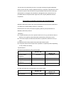
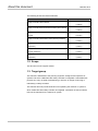
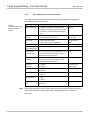
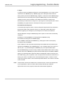
<Specifications>
General specifications of the products differ.
MELSEC-WS
Operating ambient
MELSEC-Q,
MELSEC-QS
-25 to 55°C
0 to 55°C
10 to 95%RH
5 to 95%RH
-25 to 70°C
-40 to 75°C
10 to 95%RH
5 to 95%RH
temperature
Operating ambient humidity
Storage ambient
temperature
Storage ambient humidity
EMC standards that are applicable to the products differ.
MELSEC-WS
EMC standards
EN61000-6-2, EN55011
MELSEC-Q,
MELSEC-QS
EN61131-2
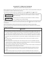
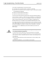
SAFETY PRECAUTIONS
(Read these precautions before using this product.)
Before using this product, please read this manual, the relevant manuals, and the safety standards carefully and
pay full attention to safety to handle the product correctly.
In this manual, the safety precautions are classified into two levels: “
DANGER” and “
CAUTION”.
DANGER
Indicates that incorrect handling may cause hazardous conditions, resulting in
CAUTION
Indicates that incorrect handling may cause hazardous conditions, resulting in
death or severe injury.
minor or moderate injury or property damage.
Under some circumstances, failure to observe the precautions given under “
CAUTION” may lead to serious
consequences.
Observe the precautions of both levels because they are important for personal and system safety.
Make sure that the end users read this manual and then keep the manual in a safe place for future reference.
[Design Precautions]
DANGER
When the MELSEC-WS safety controller detects a fault in the external power supply or itself, it turns off
the outputs. Configure an external circuit so that the connected devices are powered off according to the
output status (off) of the MELSEC-WS safety controller. Incorrect configuration may result in an accident.
When a load current exceeding the rated current or an overcurrent caused by a load short-circuit flows for
a long time, it may cause smoke and fire. To prevent this, configure an external safety circuit, such as a
fuse.
For safety relays, configure an external circuit using a device such as a fuse or breaker to protect a
short-circuit current.
When changing data and operating status, and modifying program of the running MELSEC-WS safety
controller from the PC, configure a safety circuit in the sequence program or external to the MELSEC-WS
safety controller to ensure that the entire system operates safely.
Before operating the MELSEC-WS safety controller, read the relevant manuals carefully and determine the
operating procedure so that the safety can be ensured.
Furthermore, before performing online operations for the MELSEC-WS safety controller from the PC,
determine corrective actions to be taken for communication errors caused by failure such as a poor
contact.
Create an interlock program using a reset button to prevent the MELSEC-WS safety controller from
restarting automatically after the safety function is activated and the safety controller turns off the outputs.
1
CAUTION
Ensure that an entire system using the MELSEC-WS safety controller meets the requirements for the
corresponding safety category.
The life of safety relays in the safety relay output module depends on the switching condition and/or load.
Configure a system satisfying the number of switching times of the safety relays in the module.
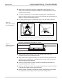
Do not install the communication cables together with the main circuit lines or power cables. Keep a
distance of 100 mm or more between them.
Failure to do so may result in malfunction due to noise
Observe the protective notes and measures.
Observe the following items in order to ensure proper use of the MELSEC-WS safety controller.
When mounting, installing and using the MELSEC-WS safety controller, observe the standards and
directives applicable in your country.
The national/international rules and regulations apply to the installation, use and periodic technical
inspection of the MELSEC-WS safety controller, in particular.
Machinery Directive 98/37/EC (from 29.12.2009 Machinery Directive 2006/42/EC)
EMC Directive 2004/108/EC
Provisition and Use of Work Equipment Directive 89/655/EC
Low-Voltage Directive 2006/95/EC
The work safety regulations/safety rules
Manufacturers and owners of the machine on which a MELSEC-WS safety controller is used are
responsible for obtaining and observing all applicable safety regulations and rules.
The notices, in particular the test notices of this manual (e.g. on use, mounting, installation or
integration into the existing machine controller), must be observed.
The test must be carried out by specialised personnel or specially qualified and authorized personnel
and must be recorded and documented and retraced at any time by third parties.
The external voltage supply of the device must be capable of buffering brief mains voltage failures of
20 ms as specified in EN 60204.
The modules of the MELSEC-WS safety controller conform to Class A, Group 1, in accordance with
EN 55011. Group 1 encompasses all the ISM devices in which intentionally generated and/or used
conductor-bound RF energy that is required for the inner function of the device itself occurs.
The MELSEC-WS safety controller fulfils the requirements of Class A (industrial applications) in
accordance with the “Interference emission” basic specifications.
The MELSEC-WS safety controller is therefore only suitable for use in an industrial environment and not
for private use
2
[Installation Precautions]
DANGER
Do not use the MELSEC-WS safety controller in flammable gas atmosphere or explosive gas atmosphere.
Doing so may result in a fire or explosion due to such as an arc caused by switching the relays.
CAUTION
Use the MELSEC-WS safety controller in an environment that meets the general specifications in this
manual. Failure to do so may result in electric shock, fire, malfunction, or damage to or deterioration of the
product.
Latch the module onto the DIN rail. Incorrect mounting may cause malfunction, failure or drop of the
module.
To ensure full electromagnetic compatibility (EMC), the mounting rail has to be connected to functional
earth (FE).
Ensure that the earthling contact is positioned correctly. The earthling spring contact of the module must
contact the DIN rail securely to allow electrical conductivity.
Shut off the external power supply for the system in all phases before mounting or removing the module.
Failure to do so may result in damage to the product.
Do not directly touch any conductive part of the module.
Doing so can cause malfunction or failure of the module.
The MELSEC-WS safety controller is only suitable for mounting in a control cabinet with at least IP 54 degree
of protection.
3
[Wiring Precautions]
DANGER
Shut off the external power supply for the system in all phases before wiring.
Failure to do so may result in electric shock or damage to the product.
The system could start up unexpectedly while you are connecting the devices.
CAUTION
Ground the FG and LG terminals to the protective ground conductor dedicated to the MELSEC-WS safety
controller.
Failure to do so may result in electric shock or malfunction.
Check the rated voltage and terminal layout before wiring to the module, and connect the cables correctly.
Connecting a power supply with a different voltage rating or incorrect wiring may cause a fire or failure.
Tighten the terminal screw within the specified torque range.
Undertightening can cause short circuit, fire, or malfunction. Overtightening can damage the screw and/or
module, resulting in drop, short circuit, or malfunction.
Prevent foreign matter such as dust or wire chips from entering the module.
Such foreign matter can cause a fire, failure, or malfunction.
Mitsubishi MELSEC-WS safety controllers must be installed in control cabinets. Connect the main power
supply to the MELSEC-WS safety controller through a relay terminal block.
Wiring and replacement of an external power supply must be performed by maintenance personnel who is
familiar with protection against electric shock.
Place the cables in a duct or clamp them.
If not, dangling cable may swing or inadvertently be pulled, resulting in damage to the module or cables or
malfunction due to poor contact.
4
[Startup and Maintenance Precautions]
DANGER
Do not touch any terminal while power is on.
Doing so will cause electric shock.
Shut off the external power supply for the system in all phases before cleaning the module or retightening
the terminal screws. Failure to do so may result in electric shock.
Tighten the terminal screw within the specified torque range. Undertightening can cause short circuit, fire,
or malfunction.
Overtightening can damage the screw and/or module, resulting in drop, short circuit, or malfunction.
Safety-oriented devices must be suitable for safety related signals.
A function interruption of safety outputs results in a loss of the safety functions so that the risk of serious
injury exists.
Do not connect any loads that exceed the rated values of the safety outputs.
Wire the MELSEC-WS safety controller so that 24 V DC signals cannot unintentionally contact safety
outputs.
Connect the GND wires of the power supply to earth so that the devices do not switch on when the safety
output line is applied to frame potential.
Use suitable components or devices that fulfill all the applicable regulations and standards. Actuators at
the outputs can be wired single-channeled. In order to maintain the respective Safety Integrity Level the
lines have to be routed in such a manner that cross circuits to other live signals can be excluded, for
example by routing them within protected areas such as in a control cabinet or in separate sheathed
cables.
5
CAUTION
Before performing online operations (Force mode) for the running MELSEC-WS safety controller from the
PC, read the relevant manuals carefully and ensure the safety.
The online operations must be performed by qualified personnel, following the operating procedure
determined at designing.
Fully understand the precautions described in the Safety Controller Setting and Monitoring Tool Operating
Manual before use.
Do not disassemble or modify the modules.
Doing so may cause failure, malfunction, injury, or a fire.
Mitsubishi does not warrant any products repaired or modified by persons other than Mitsubishi or FA Center
authorized by Mitsubishi.
Shut off the external power supply for the MELSEC-WS safety controller in all phases before mounting or
removing the module.
Failure to do so may cause the module to fail or malfunction.
After the first use of the product, do not mount/remove the module from/to the DIN rail, and the terminal block
to/from the module more than 50 times (IEC 61131-2 compliant) respectively.
Exceeding the limit of 50 times may cause malfunction.
Before handling the module, touch a grounded metal object to discharge the static electricity from the human
body.
Failure to do so may cause the module to fail or malfunction.
[Disposal Precautions]
CAUTION
When disposing of this product, treat it as industrial waste.
Disposal of the product should always occur in accordance with the applicable country-specific
waste-disposal regulations (e.g. European Waste Code 16 02 14).
6
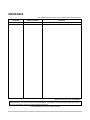
REVISIONS
*The manual number is given on the bottom left of the back cover.
Print date
*Manual number
September, 2009
SH-(NA)-080856ENG-A
Revision
First edition
Japanese manual version SH-080853-A
This manual confers no industrial property rights or any rights of any other kind, nor does it confer any patent licenses.
Mitsubishi Electric Corporation cannot be held responsible for any problems involving industrial property rights which
may occur as a result of using the contents noted in this manual.
© 2009 MITSUBISHI ELECTRIC CORPORATION
7
CONTENTS
SAFETY PRECAUTIONS...............................................................................................1
REVISIONS ....................................................................................................................7
CONTENTS ....................................................................................................................8
GENERIC TERMS AND ABBREVIATIONS..................................................................12
1.
About this document ...................................................................................13
1.1
Function of this document ..........................................................................13
1.2
Scope..........................................................................................................14
1.3
Target group................................................................................................14
1.4
Function and structure of this manual ........................................................15
1.4.1
Recommendations for familiarising your self with Setting and Monitoring
Tool..........................................................................................................15
1.4.2
1.5
2.
Recommendations for experienced users ..............................................15
Symbols and notations used ......................................................................16
On safety ....................................................................................................17
2.1
Qualified safety personnel ..........................................................................17
2.2
Correct use .................................................................................................18
3.
Installation and removal..............................................................................19
3.1
System requirements..................................................................................19
3.2
Installation...................................................................................................19
3.3
Update ........................................................................................................20
3.4
Removal......................................................................................................20
4.
The graphical user interface .......................................................................21
4.1
Start view ....................................................................................................21
4.2
Setting the desired language......................................................................22
4.3
Standard views ...........................................................................................22
4.4
Positioning windows ...................................................................................24
4.5
Hardware configuration standard view .......................................................24
4.5.1
Exercise for configuring the MELSEC-WS modules...............................26
4.5.2
Exercise for configuring the connected devices .....................................27
4.6
4.6.1
4.7
4.7.1
4.8
Logic editor standard view ..........................................................................28
Exercise for using the Logic editor..........................................................29
Report standard view..................................................................................30
Exercise for the Report standard view....................................................30
Diagnostics standard view ..........................................................................30
8
5.
Connecting to the MELSEC-WS safety controller ......................................31
5.1
5.1.1
Connecting the PC to the MELSEC-WS safety controller via RS-232 ...31
5.2
Editing the communication settings ............................................................33
5.3
Establishing a connection with the MELSEC-WS safety controller ............37
5.4
User levels in the Setting and Monitoring Tool ...........................................38
5.5
Identify project ............................................................................................39
6.
Logic programming - Function blocks.........................................................40
6.1
Function block overview .............................................................................41
6.2
Function block properties ...........................................................................43
6.3
Input and output signal connections of function blocks ..............................44
6.3.1
Function block input connections............................................................44
6.3.2
Single-channel evaluation.......................................................................45
6.3.3
Dual-channel equivalent (1 pair) evaluation ...........................................45
6.3.4
Dual-channel complementary (1 pair) evaluation ...................................46
6.3.5
Dual-channel equivalent (2 pairs) evaluation..........................................47
6.3.6
Dual-channel complementary (2 pairs) evaluation .................................48
6.3.7
Output connections of the function block................................................51
6.4
Parameterisation of function blocks............................................................52
6.4.1
Discrepancy time ....................................................................................53
6.4.2
Synchronisation time...............................................................................55
6.4.3
Fault Present...........................................................................................56
6.5
9
First steps for establishing a connection ....................................................31
Logic function blocks ..................................................................................57
6.5.1
Logic function block NOT........................................................................57
6.5.2
Logic function block AND ........................................................................58
6.5.3
Logic function block OR ..........................................................................61
6.5.4
Logic function block Exclusive OR (XOR) ..............................................64
6.5.5
Logic function block Exclusive NOR (XNOR) .........................................65
6.5.6
Function block Log Generator ................................................................66
6.5.7
Logic function block Routing 1:N ............................................................70
6.5.8
Logic function block Routing N:N............................................................71
6.5.9
Function block RS Flip-Flop....................................................................72
6.5.10
Function block Fast Shut Off...................................................................73
6.5.11
Function block Edge Detection ...............................................................77
6.5.12
Function block Clock Generator .............................................................78
6.5.13
Function blocks Event Counter (Up, Down, and Up and Down).............79
6.6
Application-specific function blocks ............................................................83
6.6.1
Application-specific function block Reset................................................83
6.6.2
Application-specific function block Restart .............................................85
6.6.3
Application-specific function block E-Stop ..............................................87
6.6.4
Application-specific function block Light Curtain Monitoring...................89
6.6.5
Application-specific function block Safety Gate Monitoring ....................91
6.6.6
Application-specific function block Two Hand Control (type IIIA, type IIIC)
................................................................................................................95
6.6.7
Application-specific function block Off-Delay Timer................................98
6.6.8
Application-specific function block On-Delay Timer................................99
6.6.9
Application-specific function block User Mode Switch..........................101
6.6.10
Application-specific function block EDM (External Device Monitoring) 103
6.6.11
Function block Multi Operator ...............................................................106
6.6.12
Function block Valve Monitoring ...........................................................109
6.6.13
Function block Magnetic Switch ...........................................................115
6.7
Function blocks for muting with parallel sensors, sequential sensors and
sensors with crossed layout .....................................................................117
6.7.1
General description...............................................................................117
6.7.2
Muting sensors......................................................................................120
6.7.3
Muting/override lamp ............................................................................121
6.7.4
Input parameters of the function block..................................................122
6.7.5
Information on wiring.............................................................................132
6.7.6
State transition from Stop to Run ..........................................................133
6.7.7
Error states and information on resetting..............................................134
6.7.8
Parallel Muting ......................................................................................134
6.7.9
Sequential Muting (Muting with sequential layout of sensor pairs).......138
6.7.10
Function block Cross Muting - Direction of movement only forwards or
backwards .............................................................................................141
6.7.11
6.8
Function block Cross Muting - Material transport in both directions.....144
Function blocks for press applications......................................................147
6.8.1
Function block Eccentric Press Contact ...............................................147
6.8.2
Function block Universal Press Contact ...............................................155
6.8.3
Function block Press Setup ..................................................................163
6.8.4
Function block Press Single Stroke ......................................................167
6.8.5
Function block Press Automatic............................................................173
6.8.6
Function block N-Break (Press with N-PSDI mode) .............................176
6.9
User defined function blocks ....................................................................186
6.9.1
Grouped Function Block .......................................................................186
6.9.2
Customized Function Block ..................................................................192
6.10
Simulation of the configuration .................................................................197
6.11
Force mode...............................................................................................200
10
7.
Transferring the system configuration ......................................................205
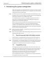
7.1
Transferring project data to the safety controller ......................................205
7.2
Compatibility check...................................................................................205
7.3
Verification of the configuration ................................................................206
7.4
Activating the write protection of the configuration in the safety
controller ...................................................................................................210
8.
Device states of the MELSEC-WS safety controller................................. 211
8.1.1
Change in the device state ...................................................................212
8.1.2
Auto RUN mode and normal state ........................................................213
9.
Report and diagnostics .............................................................................214
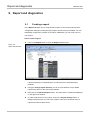
9.1
Creating a report.......................................................................................214
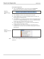
9.2
Diagnostics ...............................................................................................215
10.
11
Technical commissioning ..........................................................................217
10.1
Wiring and voltage supply.........................................................................217
10.2
Transferring the configuration...................................................................217
10.3
Technical test and commissioning ............................................................218
11.
Troubleshooting and error elimination ......................................................219
12.
Annex........................................................................................................220
12.1
List of function block status in simulation mode .......................................220
12.2
Precautions ...............................................................................................221
12.3
SICK contact .............................................................................................222
GENERIC TERMS AND ABBREVIATIONS
Generic
Description
term/abbreviation
WS0-MPL
Abbreviation for the WS0-MPL00201 MELSEC-WS safety
controller memory plug
WS0-CPU0
Abbreviation for the WS0-CPU000200 MELSEC-WS safety
controller CPU module
WS0-CPU1
Abbreviation for the WS0-CPU130202 MELSEC-WS safety
controller CPU module
WS0-XTIO
Abbreviation for the WS0-XTIO84202 MELSEC-WS safety
controller safety I/O combined module
WS0-XTDI
Abbreviation for the WS0-XTDI80202 MELSEC-WS safety
controller safety input module
WS0-4RO
Abbreviation for the WS0-4RO4002 MELSEC-WS safety controller
safety relay output module
WS0-GETH
Abbreviation for the WS0-GETH00200 MELSEC-WS safety
controller Ethernet interface module
CPU module
Generic term for the WS0-CPU0 and WS0-CPU1
Safety I/O module
Generic term for the WS0-XTIO and WS0-XTDI
Network module
Another name for the WS0-GETH
12
About this document
MELSEC-WS
1 About this document
Please read this chapter carefully before working with this manual and the
MELSEC-WS safety controller.
1.1 Function of this document
For the MELSEC-WS safety controller there are three manuals with clearly
distinguished fields of application as well as User’s Manuals (Hardware) for each
module.
This manual describes the software-supported configuration and parameterization
of the MELSEC-WS safety controller. In addition, the manual contains the
description of the diagnostics functions that are important for operation and detailed
information for the identification and elimination of errors. Use the manual in
particular for the configuration, commissioning and operation of MELSEC-WS
safety controllers.
The Safety Controller User’s Manual describes all the MELSEC-WS modules and
their functions in detail. Use this manual in particular to configure MELSEC-WS
safety controllers.
The manual instructs the technical staff of the machine manufacturer and/or of the
machine operator on the safe mounting, electrical installation, commissioning as
well as maintenance of the MELSEC-WS safety controller.
The manual does not provide instructions for operating the machine in which the
safety controller is, or will be, integrated. Information of this kind will be found in the
manuals for the machine.
The Safety Controller Ethernet Interface Module User’s Manual describes an
Ethernet interface module and its functions in detail.
The User’s Manuals (Hardware) are enclosed with each MELSEC-WS module.
They inform on the basic technical specifications of the modules and contain simple
mounting instructions. Use the User’s Manuals (Hardware) when mounting the
MELSEC-WS safety controller.
13
About this document
MELSEC-WS
The following shows the relevant manuals.
Title
Safety Controller User’s Manual
Safety Controller Ethernet Interface Module User’s Manual
Safety Controller Setting and Monitoring Tool Operating
Manual
Safety Controller CPU Module User's Manual (Hardware)
Safety Controller Safety I/O Module User's Manual
(Hardware)
Safety Controller Safety Relay Output Module User's
Manual (Hardware)
Safety Controller Ethernet Interface Module User's Manual
(Hardware)
Number
WS-CPU-U-E
(13JZ32)
WS-ET-U-E
(13JZ33)
SW1DNN-WS0ADR-B-O-E
(13JU67)
WS-CPU-U-HW
(13J200)
WS-IO-U-HW
(13J201)
WS-SR-U-HW
(13J202)
WS-ET-U-HW
(13J203)
1.2 Scope
This document is the original manual.
1.3 Target group
This manual is addressed to the planning engineers, designers and operators of
systems into which a MELSEC-WS safety controller is integrated. It also addresses
persons who carry out initial commissioning or who are in charge of servicing or
maintaining a safety controller.
This manual does not provide instructions for operating the machine or system in
which a MELSEC-WS safety controller is integrated. Information of this kind will be
found in the manuals for the machine or system.
14
About this document
MELSEC-WS
1.4 Function and structure of this manual
This manual instructs the technical personnel of the machine manufacturer or machine
operator in the software configuration, operation and diagnostics of a MELSEC-WS
safety controller using the Setting and Monitoring Tool. It only applies in combination
with the Safety Controller User’s Manual.
Chapter 2 contains fundamental safety instructions. These instructions must be read.
Note
For the acquisition of Setting and Monitoring Tool, please contact your local Mitsubishi
representative.
1.4.1
Recommendations for familiarising your self with Setting and Monitoring
Tool
We recommend the following procedure for users who want to familiarise themselves
with Setting and Monitoring Tool for the first time:
Read Chapter 4 to familiarise yourself with the graphical user interface and do the
exercises for the configuration of example applications.
1.4.2
Recommendations for experienced users
We recommend the following procedure for experienced users who have already
worked with Setting and Monitoring Tool:
Familiarise yourself with the most recent version of the software by reading Section
1.4.
The table of contents lists all the functions provided by Setting and Monitoring Tool.
Use the table of contents to obtain information about the basic functions.
15
About this document
MELSEC-WS
1.5 Symbols and notations used
Note
Notes provide special information on a device or a software function.
Warning!
An “ATTENTION” indicates concrete or potential dangers. These are intended to
ATTENTION
protect you from harm and help avoid damage to devices and systems.
Read warnings carefully and follow them!
Menus and commands
The names of software menus, submenus, options and commands, selection boxes
and windows are highlighted in bold.
Example: Click Edit in the File menu.
Key
Keys are shown in uppercase.
Keys to be pressed sequentially are hyphenated with “-”.
Example: “CTRL+ALT+DEL” indicates to press these keys simultaneously. “F12-2”
indicates to press these keys sequentially. The key names are based on the standard
keyboard. Some users may use a keyboard with a different language layout such as
German.
16
On safety
MELSEC-WS
2 On safety
This chapter deals with your own safety and the safety of the equipment operators.
Please read this chapter carefully before working with the MELSEC-WS safety
controller.
2.1 Qualified safety personnel
The MELSEC-WS safety controller must be installed, configured, commissioned and
serviced only by qualified safety personnel.
Qualified safety personnel are defined as persons who
have undergone the appropriate technical training
and
have been instructed by the responsible machine operator in the operation of the
machine and the current valid safety guidelines
and
have access to the MELSEC-WS manuals and have read and familiarised
themselves with them.
17
On safety
MELSEC-WS
2.2 Correct use
The Setting and Monitoring Tool is used to configure a MELSEC-WS safety controller
consisting of modules of the safety controller.
The MELSEC-WS safety controller may only be used by qualified safety personnel
and only at the machine at which it was mounted and initially commissioned by
qualified safety personnel in accordance with the MELSEC-WS manuals.
Mitsubishi Electric Corporation accepts no claims for liability if the software or the
ATTENTION
devices are used in any other way or if modifications are made to the software or
the devices - even in the context of mounting and installation.
Observe the safety instructions and protective measures of the Safety Controller
ATTENTION
User’s Manual and this manual!
When implementing a safety-relevant functional logic, ensure that the regulations of
ATTENTION
the national and international rules and standards are observed, in particular the
controlling strategies and the measures for risk minimisation that are mandatory for
your application.
Note
When mounting, installing and using the MELSEC-WS safety controller, observe
the standards and directives applicable in your country.
The national and international rules and regulations apply to the installation and
use as well as commissioning and periodic technical inspection of the
MELSEC-WS safety controller, in particular:
– Machinery Directive 98/37/EC
(from 29.12.2009 Machinery Directive 2006/42/EC)
– EMC Directive 2004/108/EC,
– Provision and Use of Work Equipment Directive 89/655/EEC and the
supplementary Directive 35/63/EC,
– Low-Voltage Directive 2006/95/EC,
– Work safety regulations and safety rules.
The Safety Controller User’s Manual and this manual must be made available to
the operator of the machine where the MELSEC-WS safety controller is used. The
machine operator is to be instructed in the use of the device by qualified safety
personnel and must be instructed to read the manuals.
18
Installation and removal
MELSEC-WS
3 Installation and removal
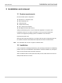
3.1 System requirements
Recommended system configuration:
Windows XP, or Windows Vista
.NET Framework 2.0
1 GHz processor
1 Gbyte work memory
1024 x 768 screen resolution
200 Mbytes free hard disk memory
Setting and Monitoring Tool is a .NET Framework application. It requires .NET
Framework Version 2.0 or higher. Information on the current .NET Framework
versions and supported operating systems is available on the Internet at
http://www.microsoft.com/
Microsoft .NET Framework Version 2.0 or higher and any other components that may
be needed can also be downloaded from http://www.microsoft.com/downloads/.
Note
Use a standard user account or higher in Windows Vista.
3.2 Installation
For the acquisition of Setting and Monitoring Tool (including information for installation),
please contact your local Mitsubishi representative. Start the installation by running the
setup.exe file and then follow the further instruction.
When an RS232-USB converter (WS0-UC-232A) is used, install a driver from the CD
ROM provided with the converter.
19
Installation and removal
MELSEC-WS
3.3 Update
For the latest version of Setting and Monitoring Tool, please contact your local
Mitsubishi representative. New software versions may contain new functions and
support new MELSEC-WS modules.
Remove the old software version before installing a new one. The working directory in
which the project data are stored is not overwritten during the new installation and is
retained.
3.4 Removal
The software can be removed as follows:
In the Windows Start menu, start Uninstall Setting and Monitoring Tool in the
Setting and Monitoring Tool programme folder.
20
The graphical user interface
MELSEC-WS
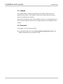
4 The graphical user interface
Note
This chapter familiarises you with the basic elements of the graphical user interface as
an introduction. This chapter does not give any information on the configuration of
MELSEC-WS modules nor any instructions for logic programming. This chapter is only
intended to explain the fundamental functioning of the Setting and Monitoring Tool on
the basis of a small section of the functions. Experienced users of Setting and
Monitoring Tool can skip this chapter.
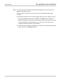
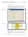
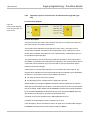
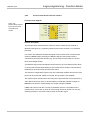
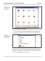
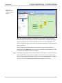
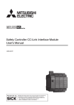
4.1 Start view
After the Setting and Monitoring Tool has been started, the start view is displayed. The
user can specify here with which of the following actions he wants to start:
Adapting the parameters of the serial interface
Establishing the connection to a physically connected device
Creating a new project
Opening an existing project file
Figure 1:
Start view with selection
of the action
21
The graphical user interface
MELSEC-WS
4.2 Setting the desired language
Click the flag icon in the menu bar at the extreme right and select the desired
language version.
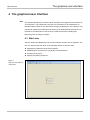
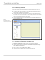
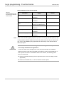
4.3 Standard views
The Setting and Monitoring Tool has the following standard views that can be
accessed via tabs below the menu bar.
Figure 2:
The view can be selected
below the menu bar
The structure of a MELSEC-WS safety controller consisting of various hardware
modules as well as the configuration of the inputs and outputs and the connected
elements are specified in the Hardware configuration view.
The function logic can be configured by means of logic function blocks and
application-specific function blocks in the Logic editor view. This view is not
available unless a CPU module has been selected beforehand in the hardware
configuration.
If the project contains at least one network module, the GETH Network Module
[13] view is available. Here you can configure the network module and the data
that are transferred to and from the network.
22
The graphical user interface
MELSEC-WS
Note
Do not save the project data while Setting and Monitoring Tool is connected to the
MELSEC-WS safety controller.
Before saving the project data, disconnect the PC from the MELSEC-WS safety
controller.
Complete information on the currently loaded project and all the settings including
the logic programming and wiring is available in the Report view. Furthermore,
additional information on the project can be entered here. All the information can be
saved in standard file formats and printed out. The scope of the report can be
compiled individually depending on the selection.
The stored error messages are displayed as a history of a connected MELSEC-WS
safety controller in the Diagnostics view.
23
The graphical user interface
MELSEC-WS
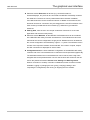
4.4 Positioning windows
Every view consists of several sub-windows that can be positioned freely. You can
change the height, width and position of each sub-window by using the mouse to
move the frame or title bar of the sub-window,
convert a sub-window into a flyout window by clicking the “Hide” button (drawing
pin symbol) on the right in the title bar. The flyout is then positioned on the left-hand
margin of the Setting and Monitoring Tool window,
move flyout windows back to their normal position by clicking the drawing pin icon
in the flyout window again.
Figure 3:
Sub-windows can be
converted to flyout menus
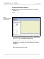
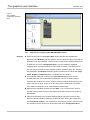
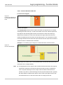
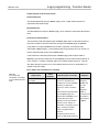
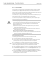
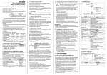
4.5 Hardware configuration standard view
The Hardware configuration window consists of the following sub-windows:
Tabs for switching between the standard views Hardware configuration, Logic
editor, Report and Diagnostics
Menu bar with the menus Project, Device, Extras
Toolbar with icons for rapid access to menus that are often used
24
The graphical user interface
MELSEC-WS
Selection window Elements; all devices (e.g. sensors/encoders or
actuators/displays, etc.) that can be connected to a MELSEC-WS safety controller
are listed here. The devices can be parameterized and renamed. In addition,
user-defined devices can be created and stored. In addition to the elements, EFI
elements can also be connected. They are dragged to the two EFI interfaces of the
CPU module, provided that the CPU module (e.g. WS0-CPU1) provides EFI
interfaces.
Parking Area; here the user can compile a selection of devices for a concrete
application and store them temporarily.
Selection window Modules; all the MELSEC-WS modules that can be combined
into a MELSEC-WS safety controller are listed here. The modules that cannot be
selected at the current configuration are greyed out. Modules that can be added to
the current configuration are identified by a green “+” symbol. The software version
number of the respective module can be selected. The number of inputs, outputs
and EFI connections is displayed for each module.
Configuration Area; the entire hardware configuration of the MELSEC-WS safety
controller and of the connected devices is created here and represented graphically.
The individual modules and connected devices can be named, have a tag name
assigned and can be parameterized. Icons for the functions are located on the left
next to the positioned modules: Switch view, Settings and Edit Tag names.
When a connection to a safety controller is established, further functions are also
available: Logging in (changing the user group), verifying (reading in and
comparing the configuration) and running or stopping the CPU module.
25
The graphical user interface
MELSEC-WS
Figure 4:
The Hardware
configuration standard
view
4.5.1
Exercise
Exercise for configuring the MELSEC-WS modules
Create a new project using Project New. All the MELSEC-WS modules are
displayed in the Modules selection window. All the modules are greyed out with the
exception of the CPU modules. Use the mouse to drag a CPU module (WS0-CPU0
or WS0-CPU1) into the Configuration Area. The CPU module is displayed
magnified there. The inputs/outputs and terminals are visible. The CPU modules
are now greyed out and the other modules (network modules, safety I/O modules)
are displayed in the Modules selection window. Furthermore, the three tabs Logic
editor, Report and Diagnostics are now displayed in the toolbar.
Create further safety I/O modules in the Configuration Area. Green arrows
indicate where the new module will be positioned. The CPU module is always
located at the extreme left. The two optional network modules follow directly to the
right of the CPU module. Only then do the safety I/O modules follow. The safety
relay output modules have to be mounted at the extreme right.
Right-click the individual modules and click Edit… in the context menu. Enter a
new tag name (module name) for the respective module and close the window by
clicking OK.
Change the positions of the modules subsequently by using the mouse to drag
them to a different position. Delete the modules by right-clicking the module and
clicking Remove module in the context menu. Alternatively, use the mouse to drag
the module to the recycle bin icon at the bottom left of the Configuration Area.
26
The graphical user interface
MELSEC-WS
4.5.2
Exercise
Exercise for configuring the connected devices
The selection structure in the Elements selection window can be expanded by
means of a mouse click. Optional: Right-click a device and select Edit current
element in the context menu. Assign a user-defined Internal item number if you
want to. This Internal item number is stored for this device.
Select some devices from the list and drag them into the Parking Area.
Note
The Parking Area serves only to increase clarity. You can compile all the required
devices here so that you do not forget any of them during the configuration.
Alternatively, you can drag the devices directly from the Elements selection window
into the Configuration Area.
Then drag a device from the Parking Area into the Configuration Area.
If the Configuration Area does not contain a module with suitable free
inputs/outputs, the device cannot be placed there. In this case, place at least one
hardware module with inputs/outputs, e.g. WS0-XTIO or WS0-XTDI, in the
Configuration Area.
When the device is moved over suitable free inputs/outputs, they light up green.
The software automatically considers the required number of inputs/outputs. Drop
the device on a suitable position. The device icon is now displayed in the view at
this point.
Drag the device to other suitable inputs/outputs or back into the Parking Area.
Delete the device by right-clicking the device icon and clicking Remove… in the
context menu. Alternatively, use the mouse to drag the device to the recycle bin
icon at the bottom left of the Configuration Area.
A device can be parameterized when it is located in the Parking Area or in the
Configuration Area. Right-click a device in the Parking Area or Configuration
Area and select Edit… from the context menu or double-click a device. The
Element settings window is opened. Depending on the type of device you can
–
assign a tag name (identifying name for the element)
–
set parameters of the device, for example discrepancy times,
ON-/OFF-delay times, test pulse active/not active, etc.
Close the Element settings window by clicking OK.
27
The graphical user interface
MELSEC-WS
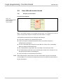
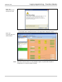
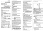
4.6 Logic editor standard view
The Setting and Monitoring Tool includes a graphical Logic editor. The function logic
is programmed by using logic and application-specific function blocks. The inputs,
function blocks and outputs are positioned on a worksheet definable in size and are
connected correspondingly.
As soon as at least one MELSEC-WS CPU module is located in the Configuration
Area, the Logic editor can be accessed via the tab of the same name.
Figure 5:
The Logic editor
The Logic editor window consists of the following sub-windows:
Menu bar with the menus Project, Device, Extras
Toolbar with icons for rapid access to menus that are often used
Tabs for switching between the standard views Hardware configuration, Logic
editor, GETH Network Module [13] (if the project contains at least one network
module), Report and Diagnostics
Specific menu bar of the logic editor with the functions Add/Delete/Rename page,
Copy/Cut/Paste/Delete elements, Undo/Redo last action, Open dialog to edit
logic result markers, Show/Hide grid, Show grid of lines/dots, Show function
block IO description, Start simulation mode and Start forcing mode
Selection window for Function Block, Inputs and Outputs respectively
28
The graphical user interface
MELSEC-WS
FB Preview window on the bottom left for displaying the important system
resources such as the number of used/available function blocks or the current
execution time (cycle time of the logic). When the cursor is moved over a function
block in the worksheet, additional information on this function block is displayed in
the FB Preview window.
Worksheets (Pages) for creating the logic and In/Out Summary Page that can be
selected alternatively by using tabs.
4.6.1
Exercise
Exercise for using the Logic editor
In the Hardware configuration standard view combine a CPU module, at least
one WS0-XTIO module and one element.
Start the Logic editor by clicking the tab of the same name.
In the selection window for Inputs, Function Block and Outputs, click Inputs and
drag an input from the list onto the worksheet.
In the selection window for Inputs, Function Block and Outputs, click Function
Block and drag an application-specific or logic function block from the list onto the
worksheet.
In the selection window for Inputs, Function Block and Outputs, click Outputs
and drag an output from the list onto the worksheet.
Connect the node of the input with an input field of the function block (node) and an
output (node) of the function block with the node of the output. To do so, click one
node with the left mouse button, hold the left mouse button pressed and drag the
cursor to the node with which the first node is to be connected.
Mark the input, function block, output and the connections by clicking them or by
dragging with the left mouse button pressed and then position as desired.
In the selection window for Inputs, Function Block and Outputs, click FB
Preview. A preview of the respective element or the details of a function block are
displayed in the FB Preview window when you move the cursor over it.
In order to delete an element right-click it and select the Delete command from the
context menu.
29
The graphical user interface
MELSEC-WS
4.7 Report standard view
Complete information on the respective project is summarised clearly in the Report
standard view. This also includes detailed wiring information at the end of the report.
The information to be summarised in a report can be selected individually from an
expandable selection list on the left-hand side. The selection is made by clicking the
check boxes.
The toolbar in the Report standard view can be used to
create a complete or partial documentation of a project.
store this documentation in the .pdf format on a data medium.
update the report.
enter additional information on the project.
4.7.1
Exercise
Exercise for the Report standard view
Start the report by clicking the tab of the same name.
Click the check boxes of the components desired for the report in the selection list
on the left-hand side. When a check mark is set or removed in the respective upper
level, the subordinate levels are marked correspondingly.
After you have completed all the changes in the selection list in the toolbar, click
Refresh Report. The report is now drawn up in the right-hand window section. It
can be saved and printed using the icons in the toolbar.
The Change Report structure tab can be used to select two different views of the
configuration information (hardware- or function-oriented).
Note
Detailed information on using the wiring information at the end of the report is
available in the Safety Controller User’s Manual.
4.8 Diagnostics standard view
In the Diagnostics standard view, all the stored error messages are displayed as a
history of a connected MELSEC-WS safety controller.
Note
Change the safety controller to the Stop state before clearing the diagnostic results.
30
Connecting to the MELSEC-WS safety controller
MELSEC-WS
5 Connecting to the MELSEC-WS safety controller
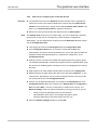
5.1 First steps for establishing a connection
This chapter describes how to establish a connection between the MELSEC-WS
safety controller and a PC or notebook.
5.1.1
Connecting the PC to the MELSEC-WS safety controller via RS-232
Connect a PC or notebook to the RS-232 interface of the CPU module.
Power on the MELSEC-WS safety controller.
Open the Setting and Monitoring Tool installed on the PC.
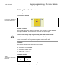
Click on Com Settings to ensure the correct communication interface has been
selected. The following dialog appears:
Figure 6:
Com settings dialog
To edit the settings click on the pencil icon to the right. The following dialog
appears:
Figure 7:
Com Settings dialog
Modify the settings if required.
Click OK. The Connection settings dialog closes.
31
Connecting to the MELSEC-WS safety controller
MELSEC-WS
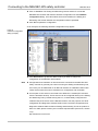
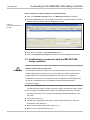
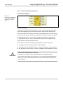
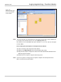
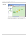
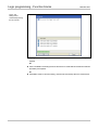
Click on Connect. The Setting and Monitoring Tool will search for connected
MELSEC-WS modules and load the hardware configuration into the Hardware
configuration dialog. Once all modules have been identified, the Setting and
Monitoring Tool will ask whether the configuration shall be uploaded.
Click Yes to upload the configuration.
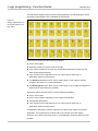
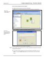
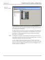
As an example, the following hardware configuration may appear:
Figure 8:
Hardware configuration
dialog (example)
Click Disconnect to go into the offline mode if you want to change the
configuration of the MELSEC-WS modules.
Note
Configuration and verification of devices that are connected to the MELSEC-WS
safety controller is generally not carried out using the Setting and Monitoring Tool,
even if they can be addressed via an RS-232 interface of a MELSEC-WS module.
These devices have their own mechanisms for configuration and verification.
An exception is EFI sensors connected to the WS0-CPU1 module (EFI elements
from the elements window). These sensors can be configured directly in the Setting
and Monitoring Tool by double-clicking the icon, or alternatively configured and
verified locally at the sensor via the RS-232 interface. For this purpose, the SICK
configuration and diagnostics software CDS is used. The SICK configuration and
diagnostics software CDS included in Setting and Monitoring Tool is the product of
SICK. For CDS, please contact your local SICK representative (see Annex, Section
12.3).
http://www.sens-control.com
32
Connecting to the MELSEC-WS safety controller
MELSEC-WS
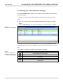
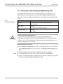
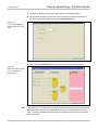
5.2 Editing the communication settings
Using the COM Settings command, you can edit and delete existing and create new
connection profiles.
To edit the connection settings, the Setting and Monitoring Tool must be in offline
mode.
If you are in online mode, click on the Disconnect button to change into offline
mode.
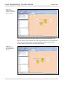
Click on COM Settings. The dialog for editing the connection profiles is opened:
Figure 9:
Connection settings dialog
All existing connection profiles are displayed here. The currently activated profile is
marked light green and with bold typeface; the profile selected for editing is marked
blue.
The symbols for editing the profiles have the following meaning:
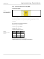
Table 1:
Symbols for editing the
connection profiles in the
Connection settings dialog
Symbol
Meaning
Save profile with the current project
Activate profile
Edit profile
Remove profile
Check profile
33
Connecting to the MELSEC-WS safety controller
MELSEC-WS
How to add a COM profile (serial port):
Click on the Add COM Profile button. The Create new profile dialog is opened.
Figure 10:
Create new profile dialog
(serial port)
Enter a name for the new profile.
Select the serial port for the new profile.
Select a fixed baud rate or activate the Auto scan checkbox.
Click OK. The dialog is closed and the new profile is displayed in the list.
To activate the new profile, select it using the left mouse button and click on the green
arrow symbol on the right. From now on, the Setting and Monitoring Tool will use this
profile.
34
Connecting to the MELSEC-WS safety controller
MELSEC-WS
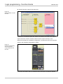
How to add a TCP/IP profile:
Note
To create a TCP/IP profile it is necessary that your MELSEC-WS safety controller
contains an Ethernet interface module (e.g. WS0-GETH) which must be configured
with a valid IP address for your network. For detailed instructions on the Ethernet
interface module configuration, please see the Safety Controller Ethernet Interface
Module User’s Manual.
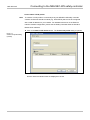
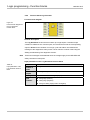
Click on the Add TCP/IP Profile button. The Create new profile dialog is opened.
Figure 11:
Create new profile dialog
(TCP/IP)
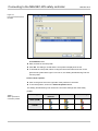
Click on the Scan button. Your network is scanned for connected network modules
and the network modules found are displayed in the list.
35
Connecting to the MELSEC-WS safety controller
MELSEC-WS
Figure 12:
List of the found network
modules
Click on the desired network module. The IP address of the device is displayed in
the IP Address field.
Enter a name for the new profile.
Click OK. The dialog is closed and the new profile is displayed in the list.
To activate the new profile, select it using the left mouse button and click on the
green arrow symbol at the right. From now on, the Setting and Monitoring Tool will
use this profile.
How to check a profile:
Click on the green tick on the right side of the profile to be checked.
To check all profiles, click on the Check all profiles button.
The Setting and Monitoring Tool checks the connection settings and marks faulty
profiles.
Table 2:
Status symbols for
connection profiles
Profile type
Profile not
Profile OK
Profile faulty
checked
Serial (COM)
TCP/IP
36
MELSEC-WS
Connecting to the MELSEC-WS safety controller
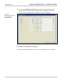
How to change the network settings of a network module:
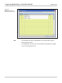
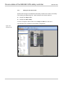
Click on the Network settings button. The Network scan dialog is opened.
Click on the Scan button. Your network is scanned for connected network modules
and the network modules found are displayed in the list.
Figure 13:
List of the found network
module
Click on the network module you want to edit.
Enter the new settings in the Edit IP Address area.
Click on the Set device config button to transfer the new settings to the device.
5.3 Establishing a connection with the MELSEC-WS
safety controller
Do not connect to the MELSEC-WS safety controller via the RS-232 and the
Ethernet interface at the same time!
ATTENTION
The MELSEC-WS safety controller can only communicate with one instance of the
Setting and Monitoring Tool at one time. Connecting to the safety controller using
multiple instances of the Setting and Monitoring Tool, either on a single PC or
multiple PCs, may result in inconsistencies of the configuration and the diagnostics
as well as in operational errors. This applies to both RS-232 and Ethernet
connections equally.
Click on the Connect button. The Setting and Monitoring Tool will try to connect to
your MELSEC-WS safety controller using the currently activated connection profile.
If a connection is established successfully, the Setting and Monitoring Tool goes
into online mode and you can perform the following activities depending on your
user level:
Log in (see Section 5.4)
Transfer the configuration to the device, upload it from the device or verify the
configuration (see Chapter 7)
Start or stop the CPU module (see Section 8.1.1)
Start the force mode (see Section 6.11)
37
Connecting to the MELSEC-WS safety controller
MELSEC-WS
5.4 User levels in the Setting and Monitoring Tool
If the Setting and Monitoring Tool is connected to the devices in a project (i.e. is in
online mode), you can switch to the user levels of the Setting and Monitoring Tool.
These user levels have different authorisations for the transfer of configurations to the
devices:
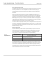
Table 3:
User level authorisations
User level
Operator
Authorisation
May edit (necessary to edit a configuration offline).
May not transfer.
Maintenance
May edit.
May only transfer verified configuration.
Authorized client
May edit.
May transfer.
Switch to the user group Operator!
If you leave the PC connected to devices without personal attendance or
ATTENTION
supervision, you must log off from the user levels Maintenance or Authorized client
and switch to the user level Operator to make sure that no unauthorized person can
transfer configurations to the devices!
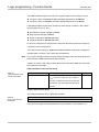
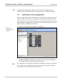
How to change the user level:
In the Hardware configuration view, click on the Log in symbol on the left side of
the Configuration Area while you are online. The Change user group dialog will
open.
Select the desired user level, enter the password and click on Log On.
Note
The default password for the user level Authorized client is “MELSECWS”.
There is no default password for the Maintenance user level. In order to log in on this
user level, you have to assign a password for it first.
38
MELSEC-WS
Connecting to the MELSEC-WS safety controller
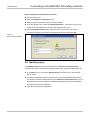
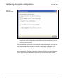
How to change the password for a user level:
Go into online mode.
Open the Hardware configuration view.
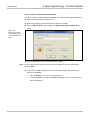
With the right mouse button, click on the CPU module.
From the context menu, select the Change password... command. If you are not
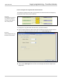
logged in as Authorized client, you will be prompted to log in now.
In the Change password dialog, select the user level for which you want to
change the password, enter the new password twice and confirm with OK.
Figure 14:
Change password dialog
5.5 Identify project
The Identify project command is equivalent to the Connect to physical device
command that can be executed upon program start of the Setting and Monitoring Tool.
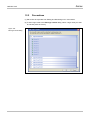
In the Device menu, choose the Identify project command. The current project
will be closed.
The Setting and Monitoring Tool will search for connected MELSEC-WS modules
and load the hardware configuration into the Hardware configuration dialog. Once
all modules have been identified, the Setting and Monitoring Tool will ask whether
the configuration shall be uploaded.
Click Yes to upload the configuration.
39
Logic programming - Function blocks
MELSEC-WS
6 Logic programming - Function blocks
The function logic of the MELSEC-WS safety controller is programmed by using
function blocks. These function blocks are certified for use in safety-relevant functions
if all safety standards are observed during implementation. The following sections
provide information on important aspects of using function blocks in the MELSEC-WS
safety controller.
Solely safety-relevant signals may be used in safety-relevant logic. Ensure
that the application fulfils all the applicable standards and regulations!
ATTENTION
If you use the function blocks described in this section in safety-relevant
applications, you must observe all the safety standards. Safety-relevant signals
have to be used for safety input and safety output signals in safety-relevant
applications.
The user is responsible for checking that the right signal sources are used for these
function blocks and that the entire implementation of the safety logic fulfils the
applicable standards and regulations. Always check the mode of operation of the
MELSEC-WS hardware and of the logic program in order to ensure that these
behave in accordance with your risk reduction strategy.
40
Logic programming - Function blocks
MELSEC-WS
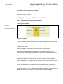
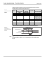
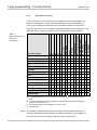
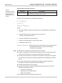
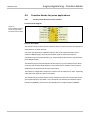
6.1 Function block overview
The MELSEC-WS safety controller uses function blocks to define the safety-oriented
logic. A configuration can encompass a maximum of 255 function blocks. There are
logic function blocks and application-specific function blocks. The following table
summarizes all the function blocks available for WS0-CPU0 and WS0-CPU1:
Table 4:
Overview of the function
blocks
Logic function blocks
Application-specific function blocks
AND
Valve Monitoring
OR
User Mode Switch
XOR
Two Hand Control type IIIA
XNOR
Two Hand Control type IIIC
Log Generator
Restart
Routing 1:N
Reset
Routing N:N
On-Delay Timer
RS Flip-Flop
Off-Delay Timer
NOT
Multi Operator
Fast Shut Off
Event Counter (Up and Down)
Edge Detection
Event Counter (Up)
Event Counter (Down)
EDM
Clock Generator
Function blocks for press applications
Universal Press Contact
Press Single Stroke
Press Setup
Press Automatic
N-Break
Eccentric Press Contact
Function blocks for muting
Sequential Muting
Parallel Muting
Cross Muting
Others
Safety Gate Monitoring
Magnetic Switch
Light Curtain Monitoring
E-Stop
41
Logic programming - Function blocks
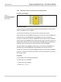
MELSEC-WS
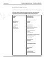
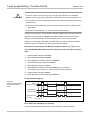
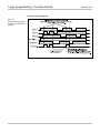
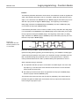
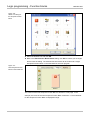
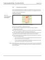
The logic editor displays all the function blocks graphically. The following figure shows
the graphic representation of the individual function blocks:
Figure 15:
Graphic representation of
the function blocks in the
logic editor
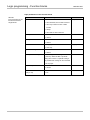
Logic function blocks have the following properties:
One or more inputs
Generally, exactly one result output of the logic
Logic function blocks do not have any configurable parameters (except for Fast
Shut Off and Edge Detection).
Logic results can be used further at one or more inputs of other logic or
application-specific function blocks.
The Routing 1:N function block can be used to pass on one output to several
outputs in the sense of a contact duplication.
The Routing N:N function block can be used to pass on up to eight input signals to
eight physical outputs directly in parallel.
Application-specific function blocks have the following properties:
One or more inputs
One or more outputs, depending on the required functionality
Configurable parameters
Logic results can be used further at one or more inputs of other logic or
application-specific function blocks.
The MELSEC-WS safety controller supports up to 255 function blocks in a specific
application. The response time is influenced by the number of function blocks.
Therefore, the number of function blocks in your application should be kept as low as
possible.
42
Logic programming - Function blocks
MELSEC-WS
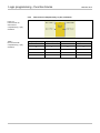
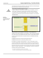
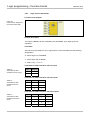
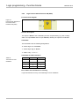
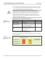
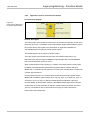
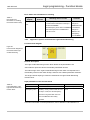
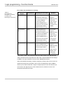
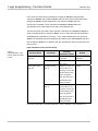
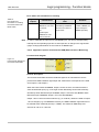
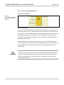
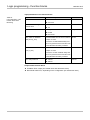
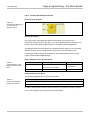
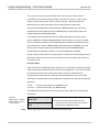
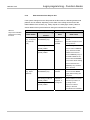
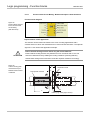
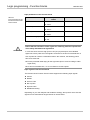
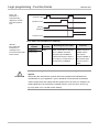
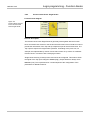
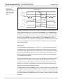
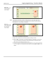
6.2 Function block properties
Function blocks offer a number of different properties that you can use. The
configurable parameters differ depending on the function block. You can double-click
the function block to access the configurable parameters and select the tab with the
desired properties. The following example shows the Safety Gate Monitoring function
block:
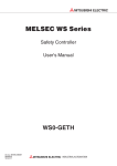
Figure 16:
Configurable parameters
of function blocks
1)
2)
3)
The number 1) to 3) for the time configuration parameters (of function block such as
Safety Gate Monitoring and Valve Monitoring) indicate:
1) input range:
an allowable range of an input value
2) input field:
a field where a value is input within the input range
3) set parameter: a configured value. The value calculated as follows is displayed:
(Configured value) = (Value input to the input field) × (10 ms)
43
Logic programming - Function blocks
MELSEC-WS
6.3 Input and output signal connections of function
blocks
Note
Some devices offer a pre-evaluation that makes the use of a special function block
with the same evaluation function superfluous. Then, you do not have to carry out this
evaluation again in the logic.
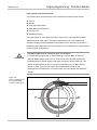
6.3.1
Function block input connections
The MELSEC-WS safety controller supports applications up to SIL3 (in accordance
with EN 62061) and Performance Level (PL) e (in accordance with EN ISO 13849-1).
Possible sources for function block inputs are one or two safety signals connected
locally to the MELSEC-WS safety controller. You can choose between the following
input evaluations (depending on the function block):
Single-channel
Dual-channel:
–
Dual-channel equivalent (1 pair)
–
Dual-channel complementary (1 pair)
–
Dual-channel equivalent (2 pairs)
–
Dual-channel complementary (2 pairs)
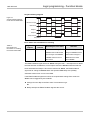
The following truth tables summarize the internal evaluation for the individual types of
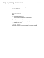
input signal evaluations of the MELSEC-WS safety controller.
Truth table
The following applies for the truth tables in this section:
“0” means logic Low or Inactive.
“1” means logic High or Active.
“x” means “any” = “0” or “1”.
Note
The Fault Present is active when the logic processing of the MELSEC-WS safety
controller detects an error in the combination or in the sequence of the input signals.
44
Logic programming - Function blocks
MELSEC-WS
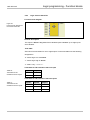
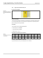
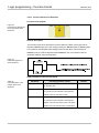
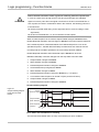
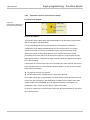
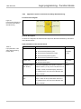
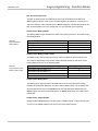
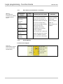
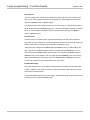
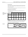
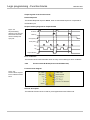
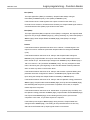
6.3.2
Single-channel evaluation
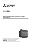
Figure 17:
Function block for
single-channel evaluation
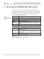
Table 5:
Single-channel evaluation
Input 1 (Pair 1)
Fault Present
Output Enable
0
0
0
1
0
1
x
1
0
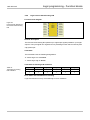
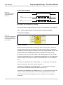
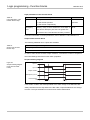
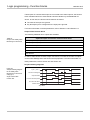
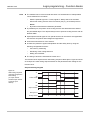
6.3.3
Dual-channel equivalent (1 pair) evaluation
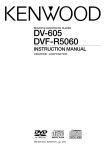
Figure 18:
Function block for
dual-channel equivalent (1
pair) evaluation
Table 6:
Dual-channel equivalent
(1 pair) evaluation
45
Input 1 (Pair 1)
Input 2 (Pair 1)
Fault Present
Output Enable
0
0
0
0
0
1
0
0
1
0
0
0
1
1
0
1
x
x
1
0
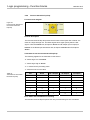
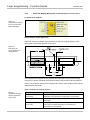
Logic programming - Function blocks
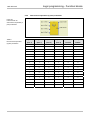
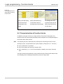
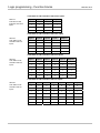
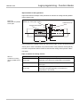
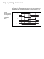
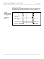
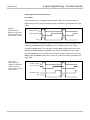
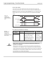
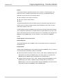
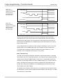
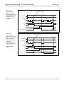
6.3.4
MELSEC-WS
Dual-channel complementary (1 pair) evaluation
Figure 19:
Function block for
dual-channel
complementary (1 pair)
evaluation
Table 7:
Dual-channel with
complementary (1 pair)
evaluation
Input 1 (Pair 1)
Input 2 (Pair 1)
Fault Present
Output Enable
0
0
0
0
0
1
0
0
1
0
0
1
1
1
0
0
x
x
1
0
46
Logic programming - Function blocks
MELSEC-WS
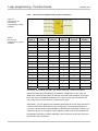
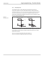
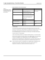
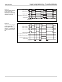
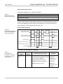
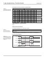
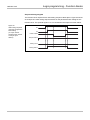
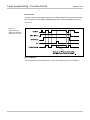
6.3.5
Dual-channel equivalent (2 pairs) evaluation
Figure 20:
Function block for
dual-channel equivalent (2
pairs) evaluation
Table 8:
Dual-channel equivalent
(2 pairs) evaluation
47
Input 1
Input 2
Input 1
Input 2
Fault
Output
(Pair 1)
(Pair 1)
(Pair 2)
(Pair 2)
Present
Enable
0
0
0
0
0
0
0
0
0
1
0
0
0
0
1
0
0
0
0
0
1
1
0
0
0
1
0
0
0
0
0
1
0
1
0
0
0
1
1
0
0
0
0
1
1
1
0
0
1
0
0
0
0
0
1
0
0
1
0
0
1
0
1
0
0
0
1
0
1
1
0
0
1
1
0
0
0
0
1
1
0
1
0
0
1
1
1
0
0
0
1
1
1
1
0
1
x
x
x
x
1
0
Logic programming - Function blocks
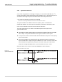
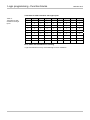
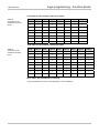
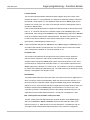
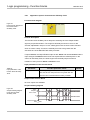
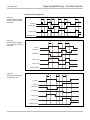
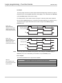
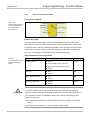
6.3.6
MELSEC-WS
Dual-channel complementary (2 pairs) evaluation
Figure 21:
Function block for
dual-channel
complementary (2 pairs)
evaluation
Table 9:
Dual-channel
complementary (2 pairs)
evaluation
Input 1
Input 2
Input 1
Input 2
Fault
Output
(Pair 1)
(Pair 1)
(Pair 2)
(Pair 2)
Present
Enable
0
0
0
0
0
0
0
0
0
1
0
0
0
0
1
0
0
0
0
0
1
1
0
0
0
1
0
0
0
0
0
1
0
1
0
0
0
1
1
0
0
0
0
1
1
1
0
0
1
0
0
0
0
0
1
0
0
1
0
0
1
0
1
0
0
1
1
0
1
1
0
0
1
1
0
0
0
0
1
1
0
1
0
0
1
1
1
0
0
0
1
1
1
1
0
0
x
x
x
x
1
0
Note that a dual-channel evaluation can already have been carried out at some
devices that have been integrated in the hardware configuration. In this case, the
WS0-XTDI or WS0-XTIO module can transfer the result of this evaluation as a single
bit via the internal FLEXBUS+ backplane bus. If there is such a pre-evaluation, you
can configure the function block on a single-channel input.
Alternatively, you can apply this pre-evaluated input signal bit to both input channels of
a function block with a dual-channel input configuration. Pre-evaluated signals can
occur in the local input and output definition of the MELSEC-WS safety controller or in
a protective device. If you apply a one-bit address to both inputs of the function block,
the MELSEC-WS safety controller regards the first connection as the logic result and
ignores the second connection.
48
Logic programming - Function blocks
MELSEC-WS
The following function blocks generate the same output value for a dual-channel input
signal that was pre-evaluated by the protective device.
Connect the pre-evaluated signals correctly!
If inputs or outputs for a dual-channel evaluation were pre-evaluated, you have to
ATTENTION
ensure that the resulting pre-evaluated signal of the dual-channel evaluation is
connected as shown in the following graphic. Do not connect both pre-evaluated
signals to the function block except if the dual-channel evaluation is to be effected in
the function block.
Figure 22:
Dual-channel
decentralised input with
single-channel safety
output
Status information can be available for input signals. In some applications an
evaluation of this status information can be important in order to specify the behaviour
of the logic functions of the MELSEC-WS safety controller. The input status specifies
whether the data transferred from the protective device to the MELSEC-WS safety
controller are:
Inactive, because this is the state at the protective device or
Inactive, because there is a fault at the protective device.
*1
No category (in accordance with with EN 954-1 or SIL or Performance Level (in
accordance with EN 62061 or EN ISO 13849-1) is defined for the input behaviour of
function blocks since the connection of the safety devices to the inputs is relevant for
this purpose and not the connection to the function block itself. However, the following
*1
signals in accordance with EN 954-1 can be realised if the connection is effected in
accordance with the specified categories:
*1 Only valid for the assumption of conformity until 29.12.2009.
From then on it will only be allowed to use the successor EN ISO 13849-1.
49
Logic programming - Function blocks
MELSEC-WS
Input signals up to Category 3 if a dual-channel input with the same test pulse
source for both input channels is used
Input signals up to Category 4 if a dual-channel input with different test pulse
sources for both input channels is used
Input signals up to Category 4 if two dual-channel inputs with different test pulse
sources for both input channel pairs is used
Output signals up to Category 3 if single-channel safety outputs with or without test
pulses are used and the necessary requirements for avoiding errors are fulfilled
Output signals up to Category 4 if single- or dual-channel safety outputs with test
pulses are used
Consult the applicable bodies of rules and regulations as well as standards!
When implementing a safety-relevant functional logic, verify that the controlling
ATTENTION
strategy and measures for risk minimization fulfil the regulations of the national
bodies of rules and regulations. Consult these bodies of rules and regulations as
well as standards in order to determine the requirements that have to be fulfilled by
your application.
50
Logic programming - Function blocks
MELSEC-WS
6.3.7
Output connections of the function block
Function blocks provide various output signal connections for connecting to physical
outputs or to other function blocks. Possible output signal connections are (depending
on the function block):
Output Enable
Static Release
Fault Present
Discrepancy Error
Synchronisation Error
Function Test Required
EDM Error (External Device Monitoring Error)
Reset Required
Restart Required
Output Enable 1
Output Enable 2
The output of a function block cannot be connected to several output elements
(physical outputs or EFI outputs), but to several subordinate function blocks. If you
want to control several physical outputs with a function block, use the Routing 1:N
function block. The output behaviour of the outputs listed above is explained at the
description of the individual function blocks.
You can choose whether error and diagnostics outputs are displayed. In the
configuration basic setting of the function blocks only the Output Enable and some
further outputs are selected (e.g. Reset Required). In order to display error and
diagnostics outputs increase the number of outputs on the In/Out Settings tab of the
function block properties.
51
Logic programming - Function blocks
MELSEC-WS
Figure 23:
I/O configuration of the
Safety Gate Monitoring
function block
Safety Gate Monitoring
Safety Gate Monitoring
I/O settings tab of the
function block with
function block with all
properties dialog for the
configuration basic
available inputs and outputs
Safety Gate Monitoring
setting
function block
6.4 Parameterisation of function blocks
In addition to the type of input (e.g. single-channel, dual-channel equivalent, etc.),
function blocks can have further parameters that are defined on the properties page of
the function block shown above.
Note
The following has to be observed when selecting time monitoring functions for the
discrepancy time, synchronisation time, pulse duration, muting time, etc.: The times
can be selected in 10 ms steps
have to be greater than the logic execution time
have a precision of +/– 10 ms in the evaluation in addition to the logic execution
time
The logic execution time depends on the number and type of the function blocks used
and is displayed in the Setting and Monitoring Tool in the logic editor.
52
Logic programming - Function blocks
MELSEC-WS
6.4.1
Discrepancy time
The discrepancy time tdis is the maximum time for which the two inputs of a
dual-channel evaluation may have invalid states without the safety-oriented logic
evaluating this state as an error. At a dual-channel equivalent evaluation both inputs
may not be complementary for longer than the configured discrepancy time. At a
dual-channel complementary evaluation both inputs may not be equivalent for longer
than the configured discrepancy time.
Figure 24:
Discrepancy time
Complementary evaluation
Equivalent evaluation
1
1
0
Input A
1
0
1
0
Input B
0
tdis
tdis
Monitoring of the discrepancy time starts with the first state change of an input. After
the discrepancy time has expired, the safety-oriented logic reports an error if both
inputs of the connection …
have not reached an equivalent state where required, or
have not reached a complementary state where required.
53
Logic programming - Function blocks
MELSEC-WS
The following truth table describes the discrepancy conditions for the dual-channel
equivalent and the dual-channel complementary input evaluation:
Table 10:
Input signals and process
image after the
discrepancy time has
expired
Dual-channel
interface
Equivalent
Complementary
Input signal
Input A
Input B
Status
0
0
Inactive
0
1
Discrepant
1
0
Discrepant
1
1
Active
0
0
Discrepant
0
1
Inactive
1
0
Active
1
1
Discrepant
Input signals furthermore have to observe the following rules with regard to the
discrepancy time:
The discrepancy time cannot be monitored for a single-channel input (i.e. it is
Inactive), irrespective of the parameter settings.
In order to delete a discrepancy time error, the dual-channel evaluation of the input
has to return to the Inactive status. The valid states are listed in the table above.
If the state of an input of the input pair changes, the state of the other input also
has to take a valid value before the discrepancy time expires.
A dual-channel evaluation can only change from Inactive to Active if the
discrepancy time has not expired.
A dual-channel evaluation CANNOT change from Active to a discrepant state and
then return to Active, irrespective of the discrepancy time. The dual-channel
evaluation has to change from Active to Inactive before it can return to Active,
whereby the requirements for the discrepancy time have to be fulfilled.
Valid values for the discrepancy time: 0 (no monitoring of the discrepancy time), 10
ms to 30,000 ms in 10 ms steps. If used, the set discrepancy time has to be greater
than the logic execution time of the MELSEC-WS safety controller.
If a discrepancy error occurs, the error is displayed by the following steps:
Output Enable changes to Inactive (fail-safe) and
Fault Present changes to Active and
Discrepancy Error (Pair 1) is set to error (for input evaluation 1/2) or
Discrepancy Error (Pair 2) is set to error (for input evaluation 3/4).
Note
If signals of tested sensors are connected to WS0-XTDI and WS0-XTIO modules, the
discrepancy time has to amount to at least the set test pulse time plus 12 ms, since a
signal change at the input of the modules can be delayed by this time.
54
Logic programming - Function blocks
MELSEC-WS
6.4.2
Synchronisation time
*1
In the case of applications according to Category 4 in accordance with EN 954-1 it
may be necessary that two dual-channel input evaluations (e.g. dual-channel input 1/2
and dual-channel input 3/4) reach the same status within the specified time.
*1 Only valid for the assumption of conformity until 29.12.2009.
From then on it will only be allowed to use the successor EN ISO 13849-1.
The synchronisation time differs from the discrepancy time: It evaluates the
relationship between two dual-channel evaluations, whereas the discrepancy time
refers to the individual channels of a dual-channel evaluation.
The input signal pairs have to observe the following rules with regard to the
synchronisation time:
If the status of a dual-channel input pair changes, the status of the other input pair
has to adopt an equivalent status before the synchronisation timer expires.
In the process, neither of the two dual-channel evaluations may have a discrepancy
error or other errors.
If the synchronisation time expires before the equivalence state is reached, the
Synchronisation Error output changes to Active. In the case of function blocks with
synchronisation time parameter (except for two-hand control) the Fault Present
output also changes to Active when a synchronisation time error occurs.
Both input pairs have to return to the status Inactive in order to delete a
synchronisation time error.
Figure 25:
Synchronisation time
55
Logic programming - Function blocks
6.4.3
MELSEC-WS
Fault Present
Various function blocks have the Fault Present diagnostics status bit. In order to use it,
activate the check box on the In/Out Settings tab of the function block properties.
When you activate the Use Fault Present check box, the additional output “Fault
Present” is displayed in the function block.
Figure 26:
Activating the Fault
Present
The Fault Present output informs you about the reason why an Output Enable signal
has adopted the Inactive state (fail-safe).
Figure 27:
Fault Present output
The Fault Present changes to Active when an error has been detected on the basis of
the configured function block parameters (e.g. Discrepancy Error, Function Test Error,
Synchronisation Error, etc.).
When the Fault Present is Active, the Output Enable changes to Inactive (fail-safe).
Deleting of the Fault Present output is described in the section of the respective
function block.
56
Logic programming - Function blocks
MELSEC-WS
6.5 Logic function blocks
6.5.1
Logic function block NOT
Function block diagram
Figure 28:
Function block diagram for
the function block NOT
General description
The inverted state of input applies at the output. If, for example, the input is Active,
the output is Inactive. This function block evaluates exactly one input.
Never control safety output signals directly with a NOT function block!
Always ensure that the usage of a NOT function lies logically before a Reset
ATTENTION
function block in your application so that unintentional starting up is prevented.
Never control safety output signals directly with a NOT function block.
Truth table
The following applies for the truth tables in this section:
“0” means logic Low or Inactive.
“1” means logic High or Active.
“x” means “any” = “0” or “1”.
Truth table for NOT
Table 11:
Truth table for the function
block NOT
Input
Output
0
1
1
0
Error states and information on resetting
Logic functions do not carry out monitoring for error conditions.
57
Logic programming - Function blocks
6.5.2
MELSEC-WS
Logic function block AND
Function block diagram
Figure 29:
Function block diagram for
the function block AND
General description
The output is Active if all the evaluated inputs are Active. Up to eight inputs are
evaluated.
Truth table
See below for truth tables for one to eight inputs. These truth tables use the following
designations:
“0” means logic Low or Inactive.
“1” means logic High or Active.
“x” means “any” = “0” or “1”.
Truth table for AND evaluation with one input
Table 12:
Truth table for AND
evaluation with one input
Input 1 Output 1
0
0
1
1
Truth table for AND evaluation with two inputs
Table 13:
Truth table for AND
evaluation with two
inputs
Input 1
Input 2 Output 1
0
x
0
x
0
0
1
1
1
Truth table for AND evaluation with three inputs
Table 14:
Truth table for AND
evaluation with three
inputs
Input 1
Input 2
0
x
Input 3 Output 1
x
0
x
0
x
0
x
x
0
0
1
1
1
1
58
Logic programming - Function blocks
MELSEC-WS
Truth table for AND evaluation with four inputs
Table 15: Truth table
for AND evaluation
with four inputs
Input 1
Input 2
Input 3
Input 4 Output 1
0
x
x
x
0
x
0
x
x
0
x
x
0
x
0
x
x
x
0
0
1
1
1
1
1
Truth table for AND evaluation with five inputs
Table 16:
Truth table for AND
evaluation with five
inputs
Input 1
Input 2
Input 3
Input 4
Input 5 Output 1
0
x
x
x
x
0
x
0
x
x
x
0
x
x
0
x
x
0
x
x
x
0
x
0
x
x
x
x
0
0
1
1
1
1
1
1
Truth table for AND evaluation with six inputs
Table 17:
Truth table for AND
evaluation with six
inputs
Input 1
Input 2
Input 3
Input 4
Input 5
Input 6 Output 1
0
x
x
x
x
x
0
x
0
x
x
x
x
0
x
x
0
x
x
x
0
x
x
x
0
x
x
0
x
x
x
x
0
x
0
x
x
x
x
x
0
0
1
1
1
1
1
1
1
Truth table for AND evaluation with seven inputs
Table 18:
Truth table for AND
evaluation with seven
inputs
59
Input 1
Input 2
Input 3
Input 4
Input 5
Input 6
Input 7 Output 1
0
x
x
x
x
x
x
0
x
0
x
x
x
x
x
0
x
x
0
x
x
x
x
0
x
x
x
0
x
x
x
0
x
x
x
x
0
x
x
0
x
x
x
x
x
0
x
0
x
x
x
x
x
x
0
0
1
1
1
1
1
1
1
1
Logic programming - Function blocks
MELSEC-WS
Truth table for AND evaluation with eight inputs
Table 19:
Truth table for AND
evaluation with eight
inputs
Input 1 Input 2 Input 3 Input 4 Input 5 Input 6 Input 7 Input 8 Output 1
0
x
x
x
x
x
x
x
0
x
0
x
x
x
x
x
x
0
x
x
0
x
x
x
x
x
0
x
x
x
0
x
x
x
x
0
x
x
x
x
0
x
x
x
0
x
x
x
x
x
0
x
x
0
x
x
x
x
x
x
0
x
0
x
x
x
x
x
x
x
0
0
1
1
1
1
1
1
1
1
1
Error states and information on resetting
Logic functions do not carry out monitoring for error conditions.
60
Logic programming - Function blocks
MELSEC-WS
6.5.3
Logic function block OR
Function block diagram
Figure 30:
Function block diagram for
the function block OR
General description
The output is Active if any one of the evaluated inputs is Active. Up to eight inputs
are evaluated.
Truth table
See below for truth tables for one to eight inputs. These truth tables use the following
designations:
“0” means logic Low or Inactive.
“1” means logic High or Active.
“x” means “any” = “0” or “1”.
Truth table for OR evaluation with one input
Table 20:
Truth table for OR
evaluation with one input
Input 1
Output 1
0
0
1
1
Truth table for OR evaluation with two inputs
Table 21:
Truth table for OR
evaluation with two inputs
61
Input 1
Input 2
Output 1
0
0
0
1
x
1
x
1
1
Logic programming - Function blocks
MELSEC-WS
Truth table for OR evaluation with three inputs
Table 22:
Truth table for OR
evaluation with three
inputs
Input 1
Input 2
Input 3
Output 1
0
0
0
0
1
x
x
1
x
1
x
1
x
x
1
1
Truth table for OR evaluation with four inputs
Table 23:
Truth table for OR
evaluation with four
inputs
Input 1
Input 2
Input 3
Input 4
Output 1
0
0
0
0
0
1
x
x
x
1
x
1
x
x
1
x
x
1
x
1
x
x
x
1
1
Truth table for OR evaluation with five inputs
Table 24:
Truth table for OR
evaluation with five
inputs
Input 1
Input 2
Input 3
Input 4
Input 5
Output 1
0
0
0
0
0
0
1
x
x
x
x
1
x
1
x
x
x
1
x
x
1
x
x
1
x
x
x
1
x
1
x
x
x
x
1
1
Truth table for OR evaluation with six inputs
Table 25:
Truth table for OR
evaluation with six
inputs
Input 1
Input 2
Input 3
Input 4
Input 5
Input 6
Output 1
0
0
0
0
0
0
0
1
x
x
x
x
x
1
x
1
x
x
x
x
1
x
x
1
x
x
x
1
x
x
x
1
x
x
1
x
x
x
x
1
x
1
x
x
x
x
x
1
1
62
Logic programming - Function blocks
MELSEC-WS
Truth table for OR evaluation with seven inputs
Table 26:
Truth table for OR
evaluation with seven
inputs
Input 1
Input 2
Input 3
Input 4
Input 5
Input 6
Input 7
Output 1
0
0
0
0
0
0
0
0
1
x
x
x
x
x
x
1
x
1
x
x
x
x
x
1
x
x
1
x
x
x
x
1
x
x
x
1
x
x
x
1
x
x
x
x
1
x
x
1
x
x
x
x
x
1
x
1
x
x
x
x
x
x
1
1
Truth table for OR evaluation with eight inputs
Table 27:
Truth table for OR
evaluation with eight
inputs
Input 1
Input 2
Input 3
Input 4
Input 5
Input 6
Input 7
Input 8
Output 1
0
0
0
0
0
0
0
0
0
1
x
x
x
x
x
x
x
1
x
1
x
x
x
x
x
x
1
x
x
1
x
x
x
x
x
1
x
x
x
1
x
x
x
x
1
x
x
x
x
1
x
x
x
1
x
x
x
x
x
1
x
x
1
x
x
x
x
x
x
1
x
1
x
x
x
x
x
x
x
1
1
Error states and information on resetting
Logic functions do not carry out monitoring for error conditions.
63
Logic programming - Function blocks
6.5.4
MELSEC-WS
Logic function block Exclusive OR (XOR)
Function block diagram
Figure 31:
Function block diagram for
the function block
Exclusive OR (XOR)
General description
The output is Active if the evaluated inputs are complementary (e.g. with contrary
state: one input Active and one input Inactive). Exactly two inputs are evaluated.
Truth table
The truth table uses the following designations:
“0” means logic Low or Inactive.
“1” means logic High or Active.
“x” means “any” = “0” or “1”.
Truth table for XOR evaluation
Table 28:
Truth table for XOR
evaluation
Input 1
Input 2
Output 1
0
0
0
0
1
1
1
0
1
1
1
0
Error states and information on resetting
Logic functions do not carry out monitoring for error conditions.
64
Logic programming - Function blocks
MELSEC-WS
6.5.5
Logic function block Exclusive NOR (XNOR)
Function block diagram
Figure 32:
Function block diagram for
the function block
Exclusive NOR (XNOR)
General description
The output is Active if the evaluated inputs are equivalent (e.g. being in the same
state: both inputs Active or both inputs Inactive). Exactly two inputs are evaluated.
Truth table
The truth table uses the following designations:
“0” means logic Low or Inactive.
“1” means logic High or Active.
“x” means “any” = “0” or “1”.
Truth table for XNOR evaluation
Table 29:
Truth table for XNOR
evaluation
Input 1
Input 2
Output 1
0
0
1
0
1
0
1
0
0
1
1
1
Error states and information on resetting
Logic functions do not carry out monitoring for error conditions.
65
Logic programming - Function blocks
6.5.6
MELSEC-WS
Function block Log Generator
Function block diagram
Figure 33:
Function block diagram for
the Log Generator
function block
General description
The Log Generator function block monitors up to eight inputs. If a defined input
condition is fulfilled at one of these inputs, the function block sets the corresponding
output to Active for the duration of one logic cycle and adds a user defined text
message to the diagnostics history which can be read out in online mode using the
Setting and Monitoring Tool diagnostic function.
Note
These text messages will be deleted when the voltage supply for the MELSEC-WS
safety controller is interrupted.
Input parameters of the Log Generator function block
Table 30:
Input parameters of the
Log Generator function
block
Parameter
Number of
Possible values
Configurable from 1 to 8
Inputs
Number of
Not configurable (= number of inputs)
Outputs
Messages
Up to 64 user defined messages per project.
Input
Rising edge (Positive)
condition
Falling edge (Negative)
Rising and falling edge (Positive & Negative)
66
Logic programming - Function blocks
MELSEC-WS
How to configure the Log Generator function block:
The following example shows the Log Generator function block with two emergency
stop buttons and a safety switch attached.
Figure 34:
Configuration example for
Log Generator with two
emergency stop buttons
and a safety switch
To configure the Log Generator function block, proceed as follows:
Connect input elements to the function block. Double click on the function block to
open the configuration dialog and click then on the In/Out Settings tab.
Figure 35:
In/Out settings for the Log
Generator function block
Choose the number of inputs that you wish to attach to the function block.
Then click the Messages tab and enter the messages that shall be output in the
diagnostics.
67
Logic programming - Function blocks
MELSEC-WS
Figure 36:
Messages of the Log
Generator function block
Note
–
The messages entered are valid globally for all Log Generator function
blocks used in a project.
–
In a single project, you can enter up to 64 different messages with a length
of up to 1,000 characters each.
68
MELSEC-WS
Logic programming - Function blocks
Then click the Message Assignment tab. Assign the desired message to each
used input and choose the input condition that must be fulfilled for the related
message to be sent (Edge=Positive, Negative or Positive & Negative).
Figure 37:
Message Assignment for
the Log Generator
function block
Error states and information on resetting
The function block Log Generator does not carry out monitoring for error conditions.
69
Logic programming - Function blocks
6.5.7
MELSEC-WS
Logic function block Routing 1:N
Function block diagram
Figure 38:
Function block diagram for
the function block Routing
1:N
General description
The function block Routing 1:N passes an input signal from a preceding function block
to up to eight output signals. The input signal can originate from a preceding function
block or directly from an input element.
Truth table
The truth table uses the following designations:
“0” means logic Low or Inactive.
“1” means logic High or Active.
“x” means “any” = “0” or “1”.
Truth table for the Routing 1:N evaluation
Table 31:
Truth table for the Routing
1:N evaluation
Input
Output 1 Output 2 Output 3 Output 4 Output 5 Output 6 Output 7 Output 8
0
0
0
0
0
0
0
0
0
1
1
1
1
1
1
1
1
1
x
0
0
0
0
0
0
0
0
Error states and information on resetting
Logic functions do not carry out monitoring for error conditions.
70
Logic programming - Function blocks
MELSEC-WS
6.5.8
Logic function block Routing N:N
Function block diagram
Figure 39:
Function block diagram for
the function block Routing
N:N
General description
The function block Routing N:N passes up to eight input signals parallel to up to eight
outputs. The input signal can originate from a preceding function block or directly from
a physical input.
Truth table
The truth table uses the following designations:
“0” means logic Low or Inactive.
“1” means logic High or Active.
Truth table for Routing N:N evaluation
Table 32:
Truth table for Routing
N:N evaluation
Intput 1
Output 1
Input 2
Output 2
Input 3
Output 3
0
0
0
0
0
0
1
1
1
1
1
1
Error states and information on resetting
Logic functions do not carry out monitoring for error conditions.
71
Logic programming - Function blocks
6.5.9
MELSEC-WS
Function block RS Flip-Flop
Function block diagram
Figure 40:
Function block diagram for
the function block RS
Flip-Flop
General description
The function block RS Flip-Flop stores the last value of the inputs Set or Reset. It is
used as a single storage cell. The Reset signal has a higher priority than the Set
signal. If Set was Active last, Q Output is Active and /Q Output (Q not Output) is
Inactive. If the Reset input was Active last, Q Output is Inactive and /Q Output is
Active.
Truth table for the function block RS Flip-Flop
The following applies for the truth table in this section:
“0” means logic Low or Inactive.
“1” means logic High or Active.
“n–1” references the preceding value.
“n” references the current value.
Table 33:
Truth table for the function
block RS Flip-Flop
Set
Reset
Qn-1 Output
Qn Output
/Q Output
0
0
0
0
1
0
0
1
1
0
0
1
0
0
1
0
1
1
0
1
1
0
0
1
0
1
0
1
1
0
1
1
0
0
1
1
1
1
0
1
Error states and information on resetting
The function block RS Flip-Flop does not carry out monitoring for error conditions.
72
Logic programming - Function blocks
MELSEC-WS
6.5.10 Function block Fast Shut Off
Function block diagram
Figure 41:
Function block diagram for
the Fast Shut Off function
block
General description
The Fast Shut Off function block is used to minimize the response time of a safety
switching path within the logic. In order for this block to be used, both the inputs and
the output for the switching path must be connected to the same I/O module (i.e.
WS0-XTIO). Furthermore, it acts as an interrupt in the logic editor since the CPU
module is bypassed when the switch off command is given. The consequence of this
is that logic between the Fast Shut Off input and Fast Shut Off output cannot hinder a
switch off when the Fast Shut Off is activated.
Example: In the following logic example, the C4000 will switch off the Q2 motor.
Figure 42:
Fast Shut Off example
Simple logic such as this can be accomplished within the Fast Shut Off function block
itself (see how to configure below).
Note
The signal path from the output of the Fast Shut Off funciton block to the physical
output that is selected in the Fast Shut Off function block must be configured in
such a way that switching off of the output of the Fast Shut Off function block
results in any case in a direct switching off of the physical output as well. Typically
the AND, Restart or EDM function blocks can be used in the signal chain for this.
An OR function block, on the other hand, does not comply to this rule.
73
Logic programming - Function blocks
MELSEC-WS
Once an input or output is attached to the Fast Shut Off function block, the output
can no longer be moved in the hardware configuration and the input can only be
moved to another position on the same safety I/O module.
Always consider the total response time of the entire safety function!
The response time of the Fast Shut Off function block is not the same as the total
ATTENTION
response time of the entire safety function. The total response time includes
multiple parameters outside of this function block. For a description of how to
calculate the total response time of the MELSEC-WS safety controller, please see
the Safety Controller User’s Manual.
Input parameters of the Fast Shut Off function block
Table 34:
Input parameters of the
Fast Shut Off function
block
Parameter
Possible parameter values
Default
Number of Inputs
Configurable from 1 to 8
1
Number of Outputs
Not configurable
1
Connect input elements to
Assigned by user. Once set, inputs
the function block.
cannot be moved in configuration view
-
to another safety I/O module.
Select output for fast shut
Assigned by user. Once set, Once set,
off.
outputs cannot be moved in
-
configuration view.
How to configure the Fast Shut Off function block:
The following example shows the function with three light curtains attached to a Fast
Shut Off function block.
Figure 43:
Configuration example for
Fast Shut Off with three
light curtains
74
Logic programming - Function blocks
MELSEC-WS
To configure the Fast Shut Off function block perform the following steps:
Connect input elements to the function block. Double click the function block to
open the configuration dialog and click the In/Out Settings tab.
Figure 44:
In/Out settings dialog for
the Fast Shut Off function
block
Choose the number of inputs which you would like to attach to the function block.
Then click the Parameter tab and choose the zone by checking the boxes.
Figure 45:
Parameter settings dialog
for the Fast Shut Off
function block
Note
If only AND logic is needed, leave the Zone 2 AND function block inputs unchecked. If
additional logic is required in the application, the inputs can be combined using the
Zone 1 and Zone 2 AND function blocks and subsequently connecting to the internal
OR function block.
75
Logic programming - Function blocks
MELSEC-WS
Finally select the output for Fast Shut Off.
Figure 46:
Output selection for Fast
Shut Off
At this point, the selected inputs and outputs are linked to each other such that the
output cannot be moved to another position and the inputs must stay on the
WS0-XTIO module in the hardware configuration. The elements which are linked are
shown in the hardware configuration in peach.
Figure 47:
Hardware configuration
view of inputs and
out-puts linked to Fast
Shut Off
These links are broken when the Fast Shut Off function block is edited or deleted.
76
Logic programming - Function blocks
MELSEC-WS
6.5.11 Function block Edge Detection
Function block diagram
Figure 48:
Function block diagram for
the function block Edge
Detection
General description
The function block Edge Detection is used to detect a rising or falling edge of the input
signal. The function block can be configured to detect a rising edge, a falling edge or
both. If an edge corresponding to the parameter settings is detected, the output Edge
Detected changes to Active (High) for the duration of one control cycle.
Input parameters of the function block
Table 35:
Input parameters of the
function block Edge
Detection
Parameter
Edge Detection
Possible parameter values
Default
Positive
Positive
Negative
Positive and Negative
Sequence/timing diagram
Figure 49:
Timing diagram for the
function block Edge
Detection
Input
Edge Detected
Edge detection = Positive
Edge Detected
Edge detection = Negative
Edge Detected
Edge detection = Positive and Negative
One control cycle
Error states and information on resetting
The function block Edge Detection does not carry out monitoring for error conditions.
77
Logic programming - Function blocks
MELSEC-WS
6.5.12 Function block Clock Generator
Function block diagram
Figure 50:
Function block diagram for
the function block Clock
Generator
General description
The function block Clock Generator is used to define a pulsed cycle output. When
Enable is Active (High), the Clock output pulses from Inactive (Low) to Active (High)
in accordance with the parameter settings of the function block. When Enable is
Inactive (Low), the Clock output becomes Inactive (Low) in accordance with the
parameter settings of the function block.
Figure 51:
Parameter diagram for
Clock Generator
Input parameters of the function block
Table 36:
Input parameters of the
function block Clock
Generator
Parameter
Stopping Mode
Possible parameter values
immediately
Default
immediately
after last clock
Clock Period
Configurable parameter based on a multiple of
2 control cycles
the cycle time of the controller. The range lies
between 2 and 65,535 control cycles.
Pulse Time
Configurable parameter based on a multiple of
1 control cycle
the cycle time of the controller. The range lies
between 1 and 65,534 control cycles. The pulse
duration has to be lower than the cycle duration.
78
Logic programming - Function blocks
MELSEC-WS
Sequence/timing diagram
Figure 52:
Timing diagram for the
function block Clock
Generator
Enable
Clock
with Stopping mode = immediately
Clock
with Stopping mode = after last clock
Error states and information on resetting
The function block Clock Generator does not carry out monitoring for error conditions.
6.5.13 Function blocks Event Counter (Up, Down, and Up and Down)
Function block diagram
Figure 53:
Function block diagram for
the function blocks Event
Counter (Up, Down, and
Up and Down)
General description
Each of the function blocks Event Counter (Up), Event Counter (Down), and Event
Counter (Up and Down) has an internal counter that counts upwards or downwards
depending on the input states of the inputs Up or Down. During upwards counting, the
Overflow output is set to Active (High) when the upper limit is reached. During
downwards counting, the Underflow output is set to Active (High) when the internal
counter has reached the value “0”. The parameter settings allow the user to determine
whether the state of the internal counter is reset automatically to “0” or to a different
value.
A transition from Inactive (Low) to Active (High), i.e., a “rising edge” at the input Up
counter increases the value of the internal counter by “1”.
A transition from Inactive (Low) to Active (High), i.e., a “rising edge” at the input
Down counter decreases the value of the internal counter by “1”.
If a transition from Inactive (Low) to Active (High), i.e., a “rising edge” at the input Up
counter, as well as at the input Down counter, occurs (applies only to the function
block Event Counter (UP and DOWN), the value of the internal counter remains
unchanged.
79
Logic programming - Function blocks
MELSEC-WS
Input parameters of the function block
Table 37:
Input parameter values for
the function blocks Event
Counter (Up, Down, and
Up and Down)
Parameter
Counter Reset
Counter Reload
Possible parameter values
Default
Manual reset to “0”
Depends on the
Automatic reset to “0”
function block.
Manual reload to value
Automatic reload to value
Overflow Limit
Integer between 1 and 65,535. The
value for the overflow limit has to
be greater than or equal to the
reload value.
Reload Value
Min. restart pulse time
Integer between 1 and 65,535
100 ms
100 ms
350 ms
Min. reload pulse time
100 ms
100 ms
350 ms
Counter Reset
The Counter Reset parameter determines what happens when the counter value
reaches the overflow limit. If this parameter is configured to Automatic reset to “0”, and
the internal counter equals the value of the overflow limit, the Overflow output
becomes Active (High) for the duration of a control cycle. The value of the internal
counter is reset to “0” subsequently.
If the Counter Reset parameter is configured to Manual reset to “0” and the overflow
limit has been reached, the Overflow output is set to Active (High). If the input Reset
changes from Inactive (Low) to Active (High) and back to Inactive (Low) in
agreement with the parameter Min. restart pulse time, the counter value is reset to “0”.
All the further Up counting pulses are ignored until a valid Reset input state occurs.
Note
If the input Reset changes from Inactive (Low) to Active (High) to Inactive (Low) in
agreement with the Min. restart pulse time, the counter value is reset to “0”
irrespective of whether the overflow limit has been reached or not.
80
Logic programming - Function blocks
MELSEC-WS
Counter Reload
The Counter Reload parameter determines what happens when the counter value
reaches the value “0”. If this parameter is configured to Automatic reload to value and
the internal counter equals “0”, the Underflow output becomes Active (High) for the
duration of a control cycle. The value of the internal counter is subsequently reset to
the value in Reload value.
If the Counter Reload parameter is configured to Manual reload to value and the lower
limit, i.e. “0”, has been reached, the Underflow output is set to Active (High). If the
input Reload value changes from Inactive (Low) to Active (High) and back to Inactive
(Low) in accordance with the Min. reload pulse time, the value of the internal counter
is reset to the value in Reload to value. All the further Down counting pulses are
ignored until a valid Reload input state occurs.
Note
If the input Reload changes from Inactive (Low) to Active (High) to Inactive (Low) in
accordance with the Min. reload pulse time, the counter value is reset to the reload
value, irrespective of whether “0” has been reached or not.
Overflow Limit
The Overflow Limit determines the upper limit of the internal counter. When the
internal counter reaches the value of the overflow limit (i.e. the upper limit), the
Overflow output changes to Active (High) until a valid reset sequence occurs. If the
Counter Reset is configured to Automatic reset to “0”, the Overflow output becomes
Active (High) for the duration of a control cycle. The controller cycle time is calculated
by means of the Setting and Monitoring Tool. The valid values for the Overflow Limit lie
between 1 and 65,535. The default is 1,000.
Reload Value
The Reload Value determines the initial value of the internal counter for applications in
which counting is carried out downwards. When the internal counter reaches “0” (i.e.,
the lower limit), the Underflow output changes to Active (High) until a valid Reload
sequence occurs. If the Counter Reload is configured to Automatic reload to value, the
Underflow output becomes Active (High) for the duration of a control cycle. The
controller cycle time is calculated by means of the Setting and Monitoring Tool. The
valid values for the reload value lie between 1 and 65,535. The default is 1,000.
Min. restart pulse time and Min. reload pulse time
The Min. restart pulse time determines the minimum duration of the Active (High)
share of an Inactive-to-Active-to-Inactive sequence that resets the value of the
internal counter to “0”. Valid values are 100 ms and 350 ms. The default is 100 ms.
The highest valid restart pulse duration amounts to 30 s (cannot be configured).
81
Logic programming - Function blocks
MELSEC-WS
Ensure that the transitions of the signals for resetting to “0” or value fulfil the
requirements!
ATTENTION
In case of a short-circuit to High (to 24 V DC) at a physical input, the evaluated
signal can have a pulse when the signal is reset due to the short-circuit detection. If
such a pulse can result in a hazardous state in the machine, the following points are
to be observed:
Ensure protected cable laying for the signal line (due to cross-circuiting to other
signal lines).
Do not reference for short-circuit detection, i.e. not test outputs.
Truth table for the function blocks Event Counter (Up, Down, and Up and Down)
The following applies for the truth table in this section:
“0” means logic Low or Inactive.
“1” means logic High or Active.
“↑” means that a rising edge has been detected at the signal input.
“n–1” references the preceding value.
“n” references the current value.
“Y” references the value of the internal counter.
“X” means “any”, e.g. Reset takes priority over the states of the Up counter and
Down counter.
Table 38:
Truth table for the function
blocks Event Counter (Up,
Down, and Up and Down)
Counter
Counter
valuen–1
valuen
0
Y
0
0
Y
0
0
0
Y
0
0
0
Overflow
Up
Down
Reset
Reload
↑
0
0
↑
1
↑
↑
Y=
limit
Overflow
Underflow
Y+1
0
0
Y+1
0
0
1
0
1
0
Y+1=
Overflow limit
Y=
Overflow limit
0
↑
0
0
Y
Y–1
0
0
1
↑
0
0
Y
Y–1
0
0
0
↑
0
0
Y
Y–1 = 0
0
1
0
↑
0
0
Y=0
Y=0
0
1
↑
↑
0
0
Y
Y
0
0
X
X
1
0
Y
Reset to “0”
0
0
X
X
0
1
Y
0
0
X
X
1
1
Y
0
0
Reload set
value
Reset to “0”
82
Logic programming - Function blocks
MELSEC-WS
Error states and information on resetting
The function blocks Event Counter (Up, Down, and Up and Down) do not carry out
monitoring for error conditions.
6.6 Application-specific function blocks
6.6.1
Application-specific function block Reset
Function block diagram
Figure 54:
Function block diagram for
the function block Reset
General description
In order to fulfil the normative requirements for safety applications on acknowledging
and cancelling a manual safety stop and the subsequent request to restart the
application, each safety logic system of a MELSEC-WS safety controller should have
a Reset function block.
The Reset signal is to be passed via an NO contact to a physical input.
The Monitored Input and Optional Input signals are combined internally. If any
Monitored Input signal changes to Inactive, the Output Enable output also becomes
Inactive and remains Inactive until a successful reset sequence occurs.
When all the Monitored Input signals (e.g. Safety gate monitoring and Emergency
stop) return to Active, the Static Release and Reset Required Indication outputs
change to Active and 1 Hz pulsed. By this means the function block indicates that it is
waiting for a reset signal sequence.
A reset-signal sequence is successful when all the Monitored Input signals remain
Active and the Reset signal changes from Low (e.g. logic “0”) to High (e.g. logic “1”)
and back to Low (e.g. logic “0”) after the Reset Required Indication output has become
Active. In this transition sequence the Active Reset signal has to fulfil the
requirements of the set parameter for the minimum reset pulse duration (either 100 ms
or 350 ms). The default is 100 ms.
83
Logic programming - Function blocks
MELSEC-WS
Ensure that the transitions of the signals for resetting fulfil the requirements!
In case of a short-circuit to High (to 24 V DC) at a physical input, the evaluated
ATTENTION
signal can have a pulse when the signal is reset due to the short-circuit detection. If
such a pulse can result in a hazardous state in the machine, the following points are
to be observed:
Ensure protected cable laying for the signal line (due to cross-circuiting to other
signal lines).
No short-circuit detection, i.e. do not reference to test outputs.
During a reset sequence, Output Enable changes to Active and the Reset Required
Indication output changes to Inactive. The further specific behaviour of the reset
sequence is described below. Each defined step has to occur in the specified
sequence - the MELSEC-WS safety controller does not continue with the next step
until the condition specified in the current step has been fulfilled.
Requests for resetting when the Monitored Input is inactive (e.g. logic “0”) or
when the MELSEC-WS safety controller changes from the stop state to the Run
state:
1. Output Enable changes to Inactive.
2. Static Release changes to Inactive.
3. Reset Required Indication changes to Inactive.
4. All the Monitored Input signals are Active.
5. Static Release changes to Active.
6. Reset Required Indication changes to Active (e.g. 1 Hz pulse).
7. A successful reset sequence is carried out (see previous sections).
8. Output Enable changes to Active.
9. Reset Required Indication changes to Inactive.
Sequence/timing diagram
Figure 55:
Sequence/timing diagram
for the function block
Reset
Reset
Monitored Input
Output Enable
Static Release
Reset Required
Indication
Stop
Run
Error states and information on resetting
The function block Reset does not carry out monitoring for error conditions.
84
Logic programming - Function blocks
MELSEC-WS
6.6.2
Application-specific function block Restart
Function block diagram
Figure 56:
Function block diagram for
the function block Restart
General description
The internal logic of the Restart function block has the same functionality as that of the
Reset function block. The Restart function block allows graphic differentiation between
the function blocks with regard to the observation of application standards for
acknowledging and cancelling a manual restart request.
The Restart signal is to be output via an NO contact.
The input signals of the Restart function block are interlinked internally. If any
Monitored Input signal changes to Inactive, Output Enable also becomes Inactive
until a successful reset sequence occurs.
When all the Monitored Input signals (e.g. outputs of the Reset function block) return
to Active, the Static Release and Restart Required Indication outputs change to
Active and 1 Hz pulsed. By this means the function block indicates that it is waiting for
a restart signal sequence.
A restart signal sequence is successful when all the Monitored Input signals remain
Active and the Restart signal changes from Low (e.g. logic “0”) to High (e.g. logic “1”)
and back to Low (e.g. logic “0”) after the Restart Required Indication output has
become Active. In this transition sequence the Active Restart signal has to fulfil the
requirements of the set parameter for the Min. Restart Pulse Time (either 100 ms or
350 ms). The default is 100 ms and requires the usage of a test output that is
referenced to the Restart input.
85
Logic programming - Function blocks
MELSEC-WS
Ensure that the transitions of the signals for restarting fulfil the requirements!
In case of a short-circuit to High (to 24 V DC) at a physical input, the evaluated
ATTENTION
signal can have a pulse when the signal is reset due to the short-circuit detection. If
such a pulse can result in a hazardous state in the machine, the following points are
to be observed:
Ensure protected cable laying for the signal line (due to cross-circuiting to other
signal lines).
No short-circuit detection, i.e. do not reference to test outputs.
When a restart sequence is successful, Output Enable changes to Active and the
Restart Required Indication output changes to Inactive. The further specific behaviour
of the restart sequence is described below. Each defined step has to occur in the
specified sequence - the MELSEC-WS safety controller does not continue with the
next step until the condition specified in the current step has been fulfilled.
Restart Required Indication when Monitored Input is Inactive or when the
MELSEC-WS safety controller changes from the stop state to the Run state:
1. Output Enable changes to Inactive.
2. Static Release changes to Inactive.
3. Restart Required Indication changes to Inactive.
4. All the Monitored Input signals are Active.
5. Static Release changes to Active.
6. Restart Required Indication changes to Active (e.g. 1 Hz pulse).
7. A successful restart sequence is carried out (see previous sections).
8. Output Enable changes to Active.
9. Restart Required Indication changes to Inactive.
Sequence/timing diagram
Figure 57:
Sequence/timing diagram
for the function block
Restart
Reset
Monitored Input
Output Enable
Static Release
Reset Required
Indication
Stop
Run
Error states and information on resetting
The function block Restart does not carry out monitoring for error conditions.
86
Logic programming - Function blocks
MELSEC-WS
6.6.3
Application-specific function block E-Stop
Function block diagram
Figure 58:
Function block diagram for
the function block E-Stop
General description
The function block E-Stop allows the implementation of an emergency stop function
with an emergency stop pushbutton.
If a corresponding dual-channel input element is configured in the hardware
configuration of the Setting and Monitoring Tool, this function block is no longer
required in the logic since the pre-evaluation is then carried out directly on the
WS0-XTDI or WS0-XTIO module. But if the error output is required for further
processing, the function block can be used to this purpose. To this purpose the two
input signals are to be configured as single-channel signals and applied to the inputs
of the function block.
If both inputs of a dual-channel input are connected to the same input bit, the function
block evaluates this as an external dual-channel evaluation. In this case the function
block behaves as follows:
The value of the Input 2 is ignored.
Any discrepancy time configured for the input pair is ignored.
In the case of emergency off pushbuttons, a Reset and/or Restart function block has
to take over the processing of the reset/restart conditions for the safety chain when
Output Enable is set to Inactive. This can also be necessary for emergency off
pushbuttons with a combined push-/pull-to-unlatch mechanism.
In as far as configured, the Fault Present output can also be monitored by connection
to the function block.
87
Logic programming - Function blocks
MELSEC-WS
Input parameters of the function block
Table 39:
Input parameters of the
function block E-Stop
Parameter
Possible parameter values
Inputs
Default
single channel
dual channel
dual channel equivalent
equivalent
dual channel complementary
Discrepancy
Inactive (= 0 ms), 10 ms to 30,000 ms in 10 ms steps. If
Time
used, the set discrepancy time has to be greater than
30 ms
the execution time of the MELSEC-WS safety controller.
For further information on these parameters, refer to Section 6.3 and Section 6.4.
Output of the function block
The following additional error outputs are available:
Table 40:
Output of the function
block E-Stop
Optional output connections of the function block
Discrepancy Error
Fault Present
In order to allow access to these output conditions, increase the number of outputs on
the In/Out Settings tab of the function block properties.
Sequence/timing diagram
Figure 59:
Sequence/timing diagram
for the function block
E-Stop
Input 1
Input 2
Output Enable
Discrepancy Error
Fault Present
Stop
Run
T>TDisc
T<TDisc
If the enable condition was already fulfilled at the state change of the MELSEC-WS
safety controller from the stop state to the Run state, Output Enable does not change
to Active. The input evaluation must have been Inactive beforehand.
88
Logic programming - Function blocks
MELSEC-WS
Error states and information on resetting
Table 41:
Error states and
information on resetting
the function block E-Stop
Diagnostics
Fault
outputs
Present
Discrepancy
Active
Error
Resetting the error state
Remarks
A Discrepancy Error cannot be reset until
Output Enable
the dual-channel evaluation of the input
changes to
has become Inactive.
Inactive and the
The Discrepancy Error returns to Inactive Fault Present
when both inputs return to Active and
changes to
there is no error.
Active, if the
Discrepancy
Error is Active.
6.6.4
Application-specific function block Light Curtain Monitoring
Function block diagram
Figure 60:
Function block diagram for
the function block Light
Curtain Monitoring
General description
The Light Curtain Monitoring function block allows the implementation of a
semiconductor protective device functionality with ESPE devices.
The internal logic of the Light Curtain Monitoring function block corresponds to the
functionality of the function block E-Stop, however with a limited parameter selection.
The single-channel input type cannot be selected in the Light Curtain Monitoring
function block.
Input parameters of the function block
Table 42:
Input parameters of the
Light Curtain Monitoring
function block
Parameter
Inputs
Discrepancy Time
Possible parameter values
dual-channel equivalent
Inactive (= 0 ms), 10 ms to 500 ms in 10
Default
dual-channel equivalent
30 ms
ms steps. If used, the set discrepancy
time has to be greater than the scan
time of the MELSEC-WS safety
controller.
For further information on these parameters, refer to Section 6.3 and Section 6.4.
89
Logic programming - Function blocks
MELSEC-WS
Output of the function block
The following additional error outputs are available:
Table 43:
Output of the Light Curtain
Monitoring function block
Optional output connections of the function block
Discrepancy Error
Fault Present
In order to allow access to these output connections, increase the number of outputs
on the In/Out Settings tab of the function block properties.
90
Logic programming - Function blocks
MELSEC-WS
6.6.5
Application-specific function block Safety Gate Monitoring
Function block diagram
Figure 61:
Function block diagram for
the function block Safety
Gate Monitoring
General description
In as far as configured, the Fault Present output can also be monitored by connection
to the function block.
Input parameters of the function block
Table 44:
Input parameters of the
Safety Gate Monitoring
function block
Parameter
Inputs
Possible parameter values
Default
single channel
dual channel
dual channel equivalent (1 pair)
equivalent
dual channel complementary (1 pair)
(1 pair)
dual channel equivalent (2 pairs)
dual channel complementary (2 pairs)
Function Test
No function test
No function
Function test required
test
Discrepancy Time
Can be set separately for the inputs 1/2 and 3/4.
(Pair 1/Pair 2)
Values: Inactive (= 0 ms), 10 ms to 30,000 ms in 10
30 ms
ms steps. If used, the set discrepancy time has to
be greater than the scan time of the MELSEC-WS
safety controller.
Synchronization
Inactive (= 0 ms), 10 ms to 30,000 ms in 10 ms
Time
steps. If used, the set synchronization time has to
be greater than the scan time of the MELSEC-WS
safety controller.
91
300 ms
Logic programming - Function blocks
MELSEC-WS
If both inputs of a dual-channel input are connected to the same input bit, the function
block evaluates this as an external dual-channel evaluation by the distributed I/O
device. In this case, the function block behaves as follows:
The value of the Input 2 is ignored.
Any discrepancy time configured for the input pair is ignored.
For further information on these parameters, refer to Section 6.3 and Section 6.4.
Output of the function block
The following additional error outputs are available:
Table 45:
Output of the Safety Gate
Monitoring function block
Optional output connections of the function block
Discrepancy Error (Pair1)
Discrepancy Error (Pair2)
Function Test Required
Synchronization Error
Function Test Error
Fault Present
In order to allow access to these output connections, increase the number of outputs
on the In/Out Settings tab of the function block properties. For further information on
these parameters, refer to Section 6.3 and Section 6.4.
Sequence/timing diagrams
Figure 62:
Sequence/timing diagram
for the Safety Gate
Monitoring function block,
Category 2,
single-channel with
function test
Input 1 (Pair 1)
Function Test Signal
Output Enable
Function Test Required
Function Test Error
Fault Present
Stop
Run
92
Logic programming - Function blocks
MELSEC-WS
Figure 63:
Sequence/timing diagram
for the Safety Gate
Monitoring function block,
Category 4, dual-channel
without function test
Input 1 (Pair 1)
Input 2 (Pair 2)
Output Enable
Discrepancy Error (Pair 1)
Fault Present
Stop
Figure 64:
Sequence/timing diagram
for the Safety Gate
Monitoring function block,
Category 4, dual-channel
(2 pairs) without function
test
T<T Discrepancy T<T Discrepancy
Run
T>=T Discrepancy T<T Discrepancy
Input 1 (Pair 1)
Input 2 (Pair 1)
Input 1 (Pair 2)
Input 2 (Pair 2)
Output Enable
Discrepancy Error (Pair 1)
Discrepancy Error (Pair 2)
Synchronization Error
Fault Present
Stop
93
Run
T<Tsynchronization T>=Tsynchronization
Tsynchronization
T<T Discrepancy
Logic programming - Function blocks
MELSEC-WS
Error states and information on resetting
Table 46:
Error states and
information on resetting
the Safety Gate
Monitoring function block
Diagnostics
outputs
Discrepancy Error
Fault Present
Active
Resetting the error state
Remarks
A Discrepancy Error cannot be
Output Enable
reset until both inputs of the
changes to
dual-channel input evaluation
Inactive (fail-safe)
have become Inactive.
and the Fault
The Discrepancy Error
Present changes
changes to Inactive when a
to Active, if the
sequence has been detected
Discrepancy Error
that sets Output Enable to
is Active.
Active and there is no error.
Synchronization
Active
Error
A Synchronization Error
Output Enable
cannot be reset until the
changes to
dual-channel evaluation of the
Inactive (fail-safe)
input has become Inactive.
and the Fault
The Synchronization Error
Present changes
changes to Inactive when a
to Active, if the
sequence has been detected
Synchronization
that sets Output Enable to
Error is Active.
Active and there is no error.
Function Test
Active
Error
The Function Test Error
Output Enable
changes to Inactive when a
changes to
sequence has been detected
Inactive (fail-safe)
that sets Output Enable to
and the Fault
Active and there is no error.
Present changes
to Active, if the
Function Test
Error is Active.
If the enable condition was already fulfilled at the state change of the MELSEC-WS
safety controller from the stop state to the Run state, Output Enable does not change
to Active. The input evaluation must have been Inactive beforehand.
When the MELSEC-WS safety controller changes from Stop to Run, all the errors are
deleted and all the timers restarted. If the Function Test Required output is Active
while any error state is detected, a High-Low-High sequence has to be carried out at
the Function Test Signal input in order to delete the error, fulfil the Function Test
Required and activate the output.
94
Logic programming - Function blocks
MELSEC-WS
6.6.6
Application-specific function block Two Hand Control (type IIIA, type
IIIC)
Function block diagram
Figure 65:
Function block diagrams
for the function block Two
Hand Control
General description
The function block Two Hand Control provides the logic for monitoring the inputs of a
two-hand control in accordance with EN 574.
The function block evaluates its input signals in pairs. Input 1 and Input 2 form a
dual-channel evaluation and have to be complementary. Input 3 and Input 4 form a
dual-channel evaluation and also have to be complementary. A discrepancy time can
be specified for both input pairs.
The synchronisation time is the time during which a discrepancy of the input pairs is
permissible. As specified in the standards and regulations, the synchronisation time for
a two-hand switch evaluation may not exceed 500 ms (the synchronisation time is
fixed and cannot be changed).
If both inputs of a dual-channel input pair are connected to the same input bit, the
function block evaluates this as an external dual-channel evaluation by the distributed
I/O device. In this case the function block behaves as follows:
The value of the second input is ignored.
Any discrepancy time configured for the input pair is ignored.
Output Enable only changes to Active if both dual-channel evaluations are effected
within the synchronisation time of 500 ms. If the limit of 500 ms for the synchronisation
time is exceeded, Output Enable remains Inactive until both dual-channel evaluations
have returned to Inactive and subsequently both have changed to Active within the
specifications for discrepancy time and synchronisation time.
A violation of the synchronisation time is not regarded as an error.
A violation of the discrepancy times is regarded as an error.
If the discrepancy time is exceeded or there is an input error, Output Enable changes
to Inactive (fail-safe) and the Fault Present changes to Active.
95
Logic programming - Function blocks
MELSEC-WS
If one of the two dual-channel evaluations changes to Inactive, Output Enable
changes to Inactive and remains Inactive until both dual-channel evaluations have
changed to Inactive. Output Enable does not change to Active until both
dual-channel evaluations have changed from Inactive to Active within the
specifications for the discrepancy time and synchronisation time.
The function block Two Hand Control requires a transition from Inactive to Active in
order for Output Enable to change to Active. If one or both dual-channel evaluations
are Active during a transition from Stop → Run, Output Enable does not change to
Active until both dual-channel evaluations have taken on the state Inactive and have
then changed to Active in accordance with the requirements of the function block Two
Hand Control.
Input parameters of the function block
Table 47:
Input parameters of the
function block Two Hand
Control
Function block
Two Hand Control
Parameter
Inputs
type IIIA
Discrepancy Time
Possible
parameter values
Default
dual channel
dual channel
equivalent
equivalent
Fixed specification
500 ms
with 500 ms
Two Hand Control
Discrepancy Time
Inactive (= 0 ms), 10
type IIIC
(Pair 1)
ms to 500 ms in 10
100 ms
ms steps. If used, the
set discrepancy time
has to be greater
than the scan time of
the MELSEC-WS
safety controller.
Discrepancy Time
Inactive (= 0 ms), 10
(Pair 2)
ms to 500 ms in 10
100 ms
ms steps. If used, the
set discrepancy time
has to be greater
than the scan time of
the MELSEC-WS
safety controller.
For further information on these parameters, refer to Section 6.3 and Section 6.4.
96
Logic programming - Function blocks
MELSEC-WS
Output of the function block
The following additional error outputs are available:
Table 48:
Output of the function
block Two Hand Control
Optional output connections of the function block
Discrepancy Error (Pair1)
Discrepancy Error (Pair2)
Fault Present
In order to allow access to these output connections, increase the number of outputs
on the In/Out Settings tab of the function block properties. For further information on
these parameters, refer to Section 6.3 and Section 6.4.
Sequence/timing diagram
Figure 66:
Sequence/timing diagram
for the function block Two
Hand Control typelllC
Input 1 (Pair 1-NO)
Input 2 (Pair 1-NC)
Input 3 (Pair 2-NO)
Input 4 (Pair 2-NC)
Output Enable
Discrepancy Error (Pair 1)
Discrepancy Error (Pair 2)
Fault Present
Stop
Run
T>TDiscrepancy
T>TDiscrepancy
Error states and information on resetting
Table 49:
Error states and
information on resetting
the function block Two
Hand Control
Diagnostics
Fault
outputs
Present
Discrepancy
Error
Active
Resetting the error state
Remarks
A Discrepancy Error cannot be reset
Output Enable
until the dual-channel evaluation of the
changes to
input has become Inactive.
Inactive and the
The Discrepancy Error returns to
Fault Present
Inactive when both inputs return to
changes to
Active and there is no error.
Active, if the
Discrepancy Error
is Active.
97
Logic programming - Function blocks
6.6.7
MELSEC-WS
Application-specific function block Off-Delay Timer
Function block diagram
Figure 67:
Function block diagram for
the function block
Off-Delay Timer
General description
The function block Off-Delay Timer delays the switching-off of the Output Enable
signal by a specified duration. The range for this delay amounts to 10 ms to 300
seconds, adjustable in steps of 10 ms. A delay period of 0 seconds is also valid and
does not cause a delay. If used, the set delay time has to be greater than the
execution time of the MELSEC-WS safety controller.
If Input is Active, the Output Enable output is also Active and remains Active until the
Input changes to Inactive and the timer has expired after the defined period. In the
case of an Off-Delay Timer, the timer begins with the delay sequence when a
transition of the input from Active to Inactive occurs.
Input parameters of the function block
Table 50:
Input parameters of the
function block Off-Delay
Timer
Parameter
Delay Time
Possible parameter values
OFF delay time (t): 0 to 300,000 ms in steps of 10 ms. If
Default
0 ms
used, the set OFF delay time has to be greater than the
execution time of the MELSEC-WS safety controller.
Output of the function block
No error outputs are available.
Sequence/timing diagram
Figure 68:
Sequence/timing diagram
for the function block
Off-Delay Timer
Input
Setpoint
Timer value
0
Output Enable
Stop
Start
98
Logic programming - Function blocks
MELSEC-WS
Error states and information on resetting
The function block Off-Delay Timer does not carry out monitoring for error conditions.
6.6.8
Application-specific function block On-Delay Timer
Function block diagram
Figure 69:
Function block diagram for
the function block
On-Delay Timer
General description
The function block On-Delay Timer delays the switching-on of the Output Enable
signal by a specified duration. The range for this delay amounts to 10 ms to 300
seconds, adjustable in steps of 10 ms. A delay period of 0 seconds is also valid and
does not cause a delay. If used, the set delay time has to be greater than the
execution time of the MELSEC-WS safety controller.
In the case of an On-Delay Timer, the timer begins with the delay sequence when a
transition of Input to Active occurs. After the delay sequence has expired, the Output
Enable output changes to Active and retains this state until Input changes to Inactive.
Input parameters of the function block
Table 51:
Input parameters of the
function block On-Delay
Timer
Parameter
Delay Time
Possible parameter values
ON delay time (t): 0 to 300,000 ms in steps of 10 ms. If used,
the set ON delay time has to be greater than the execution
time of the MELSEC-WS safety controller.
Output of the function block
No error outputs are available.
99
Default
0 ms
Logic programming - Function blocks
MELSEC-WS
Sequence/timing diagram
Figure 70:
Sequence/timing diagram
for the function block
On-Delay Timer
Input
Setpoint
Timer value
0
Output Enable
Fault Present
Stop
Start
Error states and information on resetting
The function block On-Delay Timer does not carry out monitoring for error conditions.
100
Logic programming - Function blocks
MELSEC-WS
6.6.9
Application-specific function block User Mode Switch
Function block diagram
Figure 71:
Function block diagram for
the function block User
Mode Switch
General description
The function block User Mode Switch selects an output depending on an input value.
Output x is Active if Input x is Active.
The function block supports 2 to 8 inputs and the corresponding outputs.
Several inputs may not be Active simultaneously. If more than one input is Active, the
input/output pair that was Active first is kept Active for two seconds. After two
seconds, the Fault Present changes to Active and all the outputs change to Inactive.
All the outputs remain Inactive when the MELSEC-WS safety controller changes from
the Stop to the Run state and when several inputs are Active during the first function
evaluation. After two seconds, the Fault Present then changes to Active.
Not all the inputs may be Inactive simultaneously. If all the inputs are Inactive, the
input/output pair that was Active last is kept Active for two seconds. After two
seconds, the Fault Present changes to Active and all the outputs change to Inactive.
In as far as configured, the Fault Present output can also be monitored by connection
to the function block.
Truth table
The truth table uses the following designations:
“0” means logic Low or Inactive.
“1” means logic High or Active.
“x” means “any” = “0” or “1”.
101
Logic programming - Function blocks
MELSEC-WS
Truth table for the function block User Mode Switch
Table 52:
Truth table for the function
block User Mode Switch
Input
Output
1
2
3
4
5
6
7
8
1
2
3
4
5
6
7
8
Fault Present
1
0
0
0
0
0
0
0
1
0
0
0
0
0
0
0
0
0
1
0
0
0
0
0
0
0
1
0
0
0
0
0
0
0
0
0
1
0
0
0
0
0
0
0
1
0
0
0
0
0
0
0
0
0
1
0
0
0
0
0
0
0
1
0
0
0
0
0
0
0
0
0
1
0
0
0
0
0
0
0
1
0
0
0
0
0
0
0
0
0
1
0
0
0
0
0
0
0
1
0
0
0
0
0
0
0
0
0
1
0
0
0
0
0
0
0
1
0
0
0
0
0
0
0
0
0
1
0
0
0
0
0
0
0
1
0
x
x
x
x
x
x
x
x
x
0
0
0
0
0
0
0
1
Input parameters of the function block
None.
Output of the function block
The following additional error outputs are available:
Table 53:
Output of the function
block User Mode Switch
Optional output connections of the function block
Fault Present
For further information on these parameters, refer to Section 6.3 and Section 6.4.
Sequence/timing diagram
Figure 72:
Sequence/timing diagram
for the function block User
Mode Switch (Number of
Inputs: 2)
Input 1
Input 2
Output 1
Output 2
2s
Fault Present
Stop
<2s
Run
102
Logic programming - Function blocks
MELSEC-WS
Error states and information on resetting
Table 54:
Error states and
information on resetting
the function block User
Mode Switch
Diagnostics
outputs
Fault Present
Fault Present
More than one input
Resetting the error
state
Remarks
The Fault Present returns
When the Fault
Active for more than
immediately to Inactive
Present is Active, the
2 seconds.
when the error state no
output changes to
Or:
longer exists.
Inactive (fail-safe).
All the inputs
Inactive for more
than 2 seconds.
Note
In order to eliminate the input error at the Active input, you can for example briefly
interrupt the corresponding input line or test output line. A change in the signal state
(High-Low-High) also deletes an error state of an Active input.
6.6.10 Application-specific function block EDM (External Device Monitoring)
Function block diagram
Figure 73:
Function block diagram for
the function block EDM
General description
The function block EDM checks the feedback signal of an external device that is
present at its EDM Feedback signal input and verifies that it corresponds to the state
of its Output 1 and Output 2.
When the Fault Present is Inactive, Output 1 and 2 are set in accordance with the
value at Monitored Input (e.g. of the Light Curtain Monitoring function block already
described). When Monitored Input is Active, Output 1 and 2 are also Active. When
Monitored Input is Inactive, Output 1 and 2 are also Inactive.
Output 1 and 2 control an external device (e.g. a contactor). When the state of Output
1 and 2 changes (e.g. from Active to Inactive), the EDM Feedback signal also has to
be effected within a defined period (i.e. TEDM). This maximum EDM delay time
amounts to 100 ms to 1,000 ms.
103
Logic programming - Function blocks
MELSEC-WS
The EDM Feedback signal has to have the opposite state to that of Output 1 and 2:
If Output 1 and 2 are Active, the EDM Feedback signal has to be Inactive.
If Output 1 and 2 are Inactive, the EDM Feedback signal has to be Active.
If the EDM Feedback signal does not follow a state change of Output 1 and 2 within
the specified time (TEDM), then…
the EDM Error output changes to Active,
Fault Present changes to Active,
Output 1 changes to Inactive (fail-safe),
Output 2 changes to Inactive (fail-safe).
In as far as configured, the Fault Present output can also be processed in its logic by
connection to the function block.
The Fault Present changes to Active if the EDM Feedback signal does not adopt the
opposite state of Output 1 and 2 within the specified time.
Note
If you require a delay of Output 1 and 2, realise the output delay with another function
block before the EDM function block and not after it.
If delays of Output 1 and 2 are located behind the function block EDM, this can result
in an EDM error message.
Input parameters of the function block
Table 55:
Input parameters of the
function block EDM
Parameter
Discrepancy Time
Possible parameter values
EDM Feedback signal Maximum delay time
Default
300 ms
(TEDM): 100 ms to 1,000 ms in 10 ms steps. If
used, the set delay time has to be greater than
the execution time of the MELSEC-WS safety
controller.
Output of the function block
The following additional error outputs are available:
Table 56:
Output of the function
block EDM
Optional output connections of the function block
Fault Present
For further information on these parameters, refer to Section 6.3 and Section 6.4.
104
Logic programming - Function blocks
MELSEC-WS
Sequence/timing diagram
Figure 74:
Sequence/timing diagram
for the function block EDM
EDM Feedback
Monitored Input
EDM Error
Output 1
Output 2
Fault Present
Stop
Run
t>T EDM
Error states and information on resetting
Table 57:
Error states and
information on resetting
the function block EDM
Diagnostics
Fault
outputs
Present
EDM Error
Active
Resetting the error state
Remarks
The EDM Error changes to
Output 1 and Output 2
Inactive when the Monitored
change to Inactive and the
Input changes from Inactive
Fault Present changes to
to Active and there are no
Active when the EDM
other errors.
Error is Active.
The EDM Feedback signal has to be Active during the OFF → ON sequence to delete
the Fault Present or EDM Error, since Output1 and 2 are Inactive. After the fault has
been eliminated and Output 1 and 2 have returned to Active, the EDM Feedback
signal has to change to Inactive within the specified EDM delay time (TEDM),
otherwise another error occurs in the EDM.
If the EDM Feedback signal has a fault, the required state change from Inactive to
Active can be triggered by two methods:
Change from the Stop to the Run state. This resets the logic.
Or:
Briefly interrupt the EDM Feedback signal at the source.
105
Logic programming - Function blocks
MELSEC-WS
6.6.11 Function block Multi Operator
Function block diagram
Figure 75:
Function block diagram for
the function block Multi
Operator
General description
The function block Multi Operator is used to monitor simultaneous operation of up to
three two-hand controls. For example, several two-hand controls or foot switches can
be necessary in a press application with more than one operator in order to trigger the
downward movement of the press together. The reactivation condition forces the
reactivation of the Operator inputs after a rising or falling edge has been detected at
the Trigger Condition input.
The Static Release inputs (e.g. safety light curtains) can be connected optionally in
order to ensure that the assigned devices are Active (High) before Output Enable can
become Active (High). Resetting and restarting are handled independently of this
function block.
The Operator and Static Release inputs have to be pre-evaluated signals!
A safety-relevant evaluation of the inputs of a two-hand control has to be effected
ATTENTION
either by a different function block (e.g. Two Hand Control or Light Curtain) or as a
part of the configuration of the safety inputs (e.g. configuration of the inputs with
dual-channel evaluation).
106
Logic programming - Function blocks
MELSEC-WS
The following sequence has to be effected so that Output Enable changes to Active
(High):
1. All the Static Release inputs have to be Active (High).
2. All the Operator inputs have to be Inactive (Low).
3. All the Operator inputs have to change to Active (High).
4. All the Operator inputs and Static Release inputs have to remain Active (High).
This causes Output Enable change to Active (High).
5. The reactivation condition changes depending on the configuration of the function
block (e.g. detection of falling edge or rising edge). The reactivation condition
allows Output Enable to become Inactive (Low).
6. All the Operator inputs have to change to Inactive (Low). Every Operator input is
considered independently of the others. For example, it is possible that Operator 1
changes to Inactive (Low) and then back to Active (High) before Operator 2 has
returned to Inactive (Low). However, all the Operator inputs first have to change
to Inactive (Low) and then back to Active (High) before Output Enable can be
reset to Active (High).
7. Go to item 4 above.
Input parameters of the function block
The following parameters of the function block can be configured:
Table 58:
Input parameters for the
function block Multi
Operator
Parameter
Trigger Condition
Possible parameter values
rising edge
Default
rising edge
falling edge
Number of operators
2 operators
2 operators
3 operators
Number of Static Releases
no static release
no static
1 static release
release
2 static release
Error states and information on resetting
The function block Multi Operator does not carry out monitoring for error conditions.
107
Logic programming - Function blocks
MELSEC-WS
Sequence/timing diagram
Figure 76:
Sequence/timing diagram
for the function block Multi
Operator
108
Logic programming - Function blocks
MELSEC-WS
6.6.12 Function block Valve Monitoring
Function block diagram
Figure 77:
Function block diagram for
the function block Valve
Monitoring, for double
valve
General description
The function block Valve Monitoring allows the control and monitoring of outputs for
valve control depending on the Control input values. When a state changes at the
valve control outputs, the function block checks the Feedback input for a state change
in order to ensure that the change has taken place at the valve. The status change at
the Feedback input has to accord with the configuration settings for the ON delay
(T_ON) and OFF delay (T_OFF). Three different valve types are available: Single
valves, double valves and directional valves.
The number of Control and Feedback inputs depends on the set valve type:
The single valve encompasses Control 1 and Feedback 1.
The double valve encompasses Control 1 as well as Feedback 1 and Feedback 2.
For directional valves, Control 1, Control 2, Feedback 1 and Feedback 2 are used.
Connect the feedback signals correctly!
ATTENTION
The signals for Feedback 1 and Feedback 2 have to be protected against
short-circuits to the outputs (e.g. Output 1a, 1b, 2a and 2b) as well as against each
other (e.g. by means of protected wiring or wiring of these signals solely within the
control cabinet).
109
Logic programming - Function blocks
MELSEC-WS
The number of outputs depends on the set Valve mode:
The single valve encompasses Output 1a (Output 1b is optional)
Double valves and directional valves encompass: Output 1a and Output 2a (Output
1b and Output 2b are optional)
Output 1b is always identical with Output 1a
Output 2b is always identical with Output 2a
The function block Valve Monitoring supports both manual and automatic resetting. If
manual resetting is configured, a valid reset sequence Inactive (Low) to Active (High;
at least 100 ms or 350 ms, maximum 30 s) to Inactive (Low) has to be carried out in
order to reset the function block in case of an error state (e.g. Feedback Error or
Directional Valve Error). The outputs are not reactivated automatically after an error
and a valid reset sequence (manual or automatic) has occurred, if at least one Control
input is Active (High) at the respective moment. All the Control inputs concerned must
first change to Inactive (Low) before the outputs can be reactivated (i.e. that all the
Control inputs have to be Inactive (Low) and all the Feedback inputs have to be
Active (High)).
Ensure that the transitions of the signals for resetting fulfil the requirements
ATTENTION
of the safety standards and regulations!
In case of a short-circuit to High (to 24 V DC) at a physical input, the evaluated
signal can have a pulse when the signal is reset due to the short-circuit detection. If
such a pulse can result in a hazardous state in the machine, the following points are
to be observed:
Ensure protected cable laying for the signal line (due to cross-circuiting to other
signal lines).
No short-circuit detection, i.e. do not reference to test outputs.
110
Logic programming - Function blocks
MELSEC-WS
The components of the valve monitoring check whether the Feedback input signals
follow the Control inputs in accordance with the configuration for the ON delay (T_ON)
and OFF delay (T_OFF). If the Feedback signals do not follow the signals of the
Control inputs in accordance with the configured parameters, the outputs of the
function block are deactivated.
If an Active (High) signal is present at a Control input for a shorter period than the
configured ON delay, the output(s) is/are only Active (High) as long as the Control
input is Active (High) and the Feedback are not checked.
If an Inactive (Low) signal is present at a Control input for a shorter period than the
OFF delay, the output(s) become(s) Inactive (Low) and are interlocked until the
Feedback signal has changed its state, thus reflecting the Inactive (Low) state of the
Control input. The output(s) can be reactivated to Active (High) when the Control
input(s) change(s) from Inactive (Low) to Active (High).
If both Control inputs are Active (High) at the directional valve type, the outputs
change to Inactive (Low).
A Feedback Error occurs under the following circumstances:
If one or more Control inputs change their state and the corresponding Feedback
input does not change within the configured ON/OFF delay. The Feedback input
has to be Active (High) when the corresponding Control input is Inactive (Low) or
the Feedback input has to be Inactive (Low) when the corresponding Control input
is Active (High).
If one or more Feedback inputs are Active (High) while the corresponding Control
inputs are also Active (High) and the Continuous Monitoring when valve is active
parameter is set to “yes”.
If the Feedback input is Inactive (Low) while the Control input changes to Active
(High).
A Directional Valve Error occurs under the following circumstances:
Both Control inputs are Active (High).
If a Feedback Error or Directional Valve Error is detected, the following steps have to
be carried out in the correct sequence in order to reset the error state:
A valid reset sequence (manual or automatic) has to be carried out.
The Control input(s) has/have to change to Inactive (Low).
The corresponding Feedback input(s) has/have to change to Active (High).
111
Logic programming - Function blocks
MELSEC-WS
Input parameters of the function block
Table 59:
Input parameters of the
function block Valve
Monitoring
Parameter
Reset Condition
Possible parameter values
manual reset
Default
manual reset
auto reset
Continuous Monitoring when
without
valve is active
yes
Valve mode
Single
without
Single
Double
Directional
Max. switch-on feedback
Parameterisable from 50 ms to 3,000 ms
delay time (T_ON)
in steps of 10 ms.
50 ms
If used, the set ON feedback delay time
has to be greater than the execution time
of the MELSEC-WS safety controller.
Max. switch-off feedback delay
Parameterisable from 50 ms to 3,000 ms
time (T_OFF)
in steps of 10 ms.
50 ms
If used, the set OFF feedback delay time
has to be greater than the execution time
of the MELSEC-WS safety controller.
Min. reset pulse time
100 ms
100 ms
350 ms
Output of the function block
Feedback Error output (For double valve and directional valve)
Directional Valve Error, depending on the configuration (For directional valve)
112
Logic programming - Function blocks
MELSEC-WS
Sequence/timing diagrams
Figure 78:
Sequence/timing diagram
for single valve in manual
reset mode
T_ON
T_ON
T_OFF
T_ON
T_OFF
Control 1
Feedback 1
Output 1a/b
Feedback Error
Figure 79:
Sequence/timing diagram
for double valve in manual
reset mode
T_ON
T_OFF
T_ON
Control 1
Feedback 1
Feedback 2
Output 1a/b
Output 2a/b
Feedback Error
Figure 80:
Sequence/timing diagram
for directional valve
T_ON
Control 1
Control 2
Feedback 1
Feedback 2
Output 1a/b
Output 2a/b
Feedback Error
113
T_OFF
T_ON
T_ON
Logic programming - Function blocks
MELSEC-WS
Error states and information on resetting
Table 60:
Error states and
information on resetting
for the function block
Valve Monitoring
Diagnostics
Fault
outputs
Present
Feedback
Error
Directional
Valve Error
Active
Resetting the error state
Remarks
If manual resetting is configured, a
Output (1a, 1b, 2a, 2b)
valid reset sequence Inactive
changes to Inactive and
(Low) to Active (High; > 100 ms or
the Fault Present output
350 ms, < 30 s) to Inactive (Low)
changes to Active, if
has to be carried out in order to
Feedback Error or
reset the function block in case of
Directional Valve Error is
an error state (e.g. Feedback Error
Active.
or Directional Valve Error).
The outputs are not reactivated
automatically after an error and a
valid reset sequence (manual or
automatic) have occurred, if at
least one Control input is Active
(High) at the respective moment.
All the Control inputs concerned
must first change to Inactive
(Low) before the outputs can be
reactivated (i.e. all the Control
inputs have to be Inactive (Low)
and all the Feedback inputs have
to be Active (High)).
114
Logic programming - Function blocks
MELSEC-WS
6.6.13 Function block Magnetic Switch
Function block diagram
Figure 81:
Function block diagram for
the function block
Magnetic Switch
General description
The internal logic of the Magnetic Switch function block corresponds to the
functionality of the E-Stop function block, only with a limited parameter selection. The
function block allows graphic differentiation in accordance with the application.
The Magnetic Switch function block is a predefined function block for non-contacting
solenoid sensors or other complementary sensors for which discrepancy time
monitoring is required. When the evaluation of the complementary inputs is Active
(High), Output Enable is Active (High).
Input parameters of the function block
Table 61:
Input parameters of the
Magnetic Switch function
block
Parameter
Inputs
Discrepancy Time
Possible parameter values
Default
dual channel complementary
dual channel
dual channel equivalent
complementary
10 to 3000 ms
800 ms
Output of the function block
The following additional error outputs are available:
Table 62:
Output of the Magnetic
Switch function block
Optional output connections of the function block
Discrepancy Error
Fault Present
In order to allow access to these output connections, increase the number of outputs
on the In/Out Settings tab of the function block properties.
115
Logic programming - Function blocks
MELSEC-WS
Error states and information on resetting
Table 63:
Error states and
information on resetting
the Magnetic Switch
function block
Diagnostics
Fault
outputs
Present
Discrepancy
Error
Active
Resetting the error state
Remarks
A Discrepancy Error cannot be reset
Output Enable
until the dual-channel evaluation of
changes to Inactive
the input has become Inactive.
and the Fault
The Discrepancy Error returns to
Present changes to
Inactive when both inputs return to
Active, if the
the Active and there is no error.
Discrepancy Error is
Active.
116
Logic programming - Function blocks
MELSEC-WS
6.7
6.7.1
Function blocks for muting with parallel sensors,
sequential sensors and sensors with crossed
layout
General description
Muting is the automatic temporary bypassing of all the safety-oriented functions of the
control system or of the safety device. Muting is used when certain objects, e.g. pallets
with material, may be moved into the hazardous area. During this transportation
through electro-sensitive protective equipment (ESPE), e.g. a safety light curtain, the
muting function suppresses monitoring by the ESPE.
Muting sensors monitor the presence of the material while it is being transported.
Careful selection of the type and layout of the sensors makes it possible to
differentiate between objects and persons.
In combination with the muting sensors and the ESPE the transported object
generates an exactly defined signal sequence while it is moved through the hazardous
area. They have to ensure that all dangers are excluded when a person enters an
area protected by the ESPE (i.e. any state entailing danger has to be terminated
immediately). It has to be impossible for a person to generate the same signal
sequence as a transported object.
The placement of the muting sensors is determined by the form of the object to be
detected. To this purpose the following options are, amongst others, available with
differing numbers of sensor input signals:
two sensors
two sensors and an additional signal C1
four sensors (two sensor pairs)
four sensors (two sensor pairs) and an additional signal C1
Three different function blocks are available for muting:
muting with two sensors with crossed layout
muting with four sensors with a parallel layout of two sensor pairs
muting with four sensors with a sequential layout of two sensor pairs
117
Logic programming - Function blocks
MELSEC-WS
Since muting bypasses the safety functions of a protective device, several
requirements have to be fulfilled, as shown below, in order to ensure the safety of the
application.
Note
The muting cycle is the specified sequence of all processes that are executed
during muting.
The cycle begins when the first muting sensor is activated. The cycle ends
depending on the configuration in the function block for the muting end condition. It
is not possible to activate muting again until the preceding muting cycle has been
terminated.
Material can be transported several times within one muting cycle if the muting
conditions are maintained permanently in the process, meaning that at least one
pair of sensors remain activated permanently.
The general safety regulations and protective measures have to be observed!
ATTENTION
If you use muting, be sure to observe the following information about the correct use
of muting:
Access to the hazardous area has to be detected reliably by the ESPE or be
excluded through other measures. It has to be impossible for a person to pass by,
pass over, pass under or cross the ESPE without being detected. Observe the
manual of the ESPE for the correct installation and use of the device.
Always observe the valid applicable local, regional and national regulations and
standards applying to your application. Ensure that your application conforms to an
appropriate risk analysis and avoidance strategy.
Muting may never be used to transport a person into the hazardous area.
Mount the control devices for resetting and overriding outside the hazardous area
so that they cannot be actuated by a person located in the hazardous area.
Furthermore, when operating a control device, the operator must have full visual
command of the hazardous area.
The muting sensors have to be located in such a way that the hazardous area can
only then be accessed after an intervention in the protective field, if the state
causing the hazard has been terminated beforehand. One condition here is that the
required safety distances defined in EN 999 are observed. At least two muting
signals that are independent of each other are required.
Muting may only be activated for the period in which the object that triggered the
muting condition blocks access to the hazardous area.
Muting has to be carried out automatically, but may not depend on a single
electrical signal.
The material to be transported has to be detected along the entire length, meaning
that an interruption of the output signals may not occur (see Sensor signal gap
monitoring).
118
Logic programming - Function blocks
MELSEC-WS
Muting must be triggered by at least two independently wired signals (e.g. by
muting sensors) and may not depend completely on software signals (e.g. from a
programmable controller).
The muting condition has to be terminated immediately after the passage of the
object so that the protective device returns to its normal state that was bypassed by
muting (i.e. so that it comes back into force).
The muting sensors have to be positioned in such a way that muting cannot be
triggered unintentionally by anyone (see Figure 82).
Figure 82:
Safety when mounting
the muting sensors
A
B
A: It may not be possible to activate sensors lying opposite each other simultaneously.
B: It may not be possible to activate sensors mounted next to each other simultaneously.
Always position the muting sensors in such a way that only the material is detected
and not the conveyance means (pallet or vehicle).
Figure 83:
Detection of material
during muting
Transported material
Muting sensor
Conveyance means
Transport level
Always position muting sensors in such a way that the material can pass
unimpeded, but persons are detected reliably.
Always position the muting sensors in such a way that a minimum distance to the
detection area of the ESPE (e.g. to the light beams of a light curtain) is observed
while the material is being detected.
It has to be ensured that no persons are within the hazardous area before and
during the activation of an override.
Before you activate the override ensure that the equipment is in a perfect condition,
in particular the muting sensors (visual inspection).
When it has been necessary to activate an override, subsequently check whether
the equipment functions properly and the layout of the muting sensors.
119
Logic programming - Function blocks
MELSEC-WS
During long muting cycles (i.e. longer than 24 hours) or during longer machine
downtimes check that the muting sensors function correctly.
A muting and/or override lamp has to be used in order to signal that the muting or
override function is active. It is possible to use an external muting/override lamp or
one that is integrated in the protective device (ESPE).
Always position the muting or override lamp so that it can be seen well! It must be
possible to see the muting or override lamp from all the positions around the
hazardous area and for the system operator.
If safety-relevant information (i.e. distributed safety input values and/or safety
output values) is transferred via a safety field bus network, always take the
corresponding delay times into account. These delay times can influence both the
system behaviour as well as the requirements for the minimum safety distances
that are connected to the response times.
When an Override input is configured, test pulse outputs may not be used for the
configuration of the safety inputs.
Separate lines have to be used for the sensor signals A1 and A2 (B1 and B2).
A line that is independent of other input signals has to be used for the signals for
Reset and Reset required in order to exclude unintentional resetting of the system.
The line must furthermore be laid protected.
The total muting time cannot be set to indefinite (Inactive) without additional
precautions being taken. If the total muting time is set to Inactive, additional
measures have to be taken to ensure that no one can access the state entailing
the hazard connected with the muting condition.
6.7.2
Muting sensors
Muting sensors detect material and supply the signals required by the control system.
When the muting conditions are fulfilled, the control system can mute the protection
device on the basis of the sensor signals.
Muting sensor signals can be generated by the following external sensors:
optical sensors
inductive sensors
mechanical switches
signals from the control system
If you use optical sensors for muting applications, use sensors with a background
suppression in order to ensure that only the transported material fulfils the muting
condition. These sensors detect material only up to a specific distance. Objects that
are further away can therefore not fulfil the input conditions of the muting sensors.
120
Logic programming - Function blocks
MELSEC-WS
6.7.3
Muting/override lamp
A muting and/or override lamp has to be used in order to signal that the muting or
override function is active. It is possible to use an external muting/override lamp or
one that is integrated in the protective device (ESPE).
Note
It may be necessary to monitor the muting/override lamp(s) depending on your local,
regional and national regulations and standards.
Always position the muting or override lamp so that it can be seen well!
It must be possible to see the muting or override lamp from all the positions around
ATTENTION
121
the hazardous area and for the system operator.
Logic programming - Function blocks
6.7.4
MELSEC-WS
Input parameters of the function block
The following (function-block-specific) parameters provide additional configuration
possibilities for the muting function.
Table 64:
Input parameters of the
function blocks for
muting
Parameter
Direction Detection
Possible parameter values:
disabled– movement in both directions
Default
disabled
forward – Input pair A1/A2 must switch first
backward – Input pair B1/B2 must switch
first
Muting Start
after all muting sensors are off
Depends on the
Condition
if last muting sensor is active
function block.
Muting End
after last muting sensor
after last muting
after ESPE is clear of obstruction
sensor
Muting Total Time
Inactive, 5 s to 3600 s, resolution 1 s
5 sec
Add. Muting Time
0 ms, 200 ms, 500 ms, 1000 ms
0 ms
when ESPE is clear
Concurrency
Inactive, 10 ms to 3000 ms, resolution 10 ms. If 0 ms
monitoring time
used, the value of this parameter has to be
greater than the execution time.
Sensor signal gap
Inactive, 10 ms to 1000 ms, resolution 10 ms. If 100 ms
monitoring
used, the value of this parameter has to be
greater than the execution time.
Sequence
enabled
Depends on the
Monitoring
disabled
function block.
C1 Input
with
with
without
Override Input
with
with
without
Conveyer Input
with
with
without
Note
Min. Override Pulse
100 ms
Time
350 ms
100 ms
All the input parameters of the function block can be accessed by double-clicking the
function block and then clicking the selection field belonging to the respective
parameter.
122
Logic programming - Function blocks
MELSEC-WS
Direction Detection
Direction Detection is used when the transported material has to be moved in a
specific direction. The Direction Detection depends on the sequence in which the
muting sensors are activated. The default is “disabled”.
If Direction Detection is disabled, the material to be transported can be moved in both
directions in order to fulfil the muting conditions. In this case it is not relevant which
sensor pair is activated first.
If “forward” was selected as the direction, the muting sensor pairs have to be activated
in the sequence (A1/A2) before (B1/B2). Muting is not possible in the opposite
direction. Muting is terminated by a transition from four active sensors to an inactive
sensor pair “B” (0 or 1 sensor active).
If “backward” was selected as the direction, the muting sensor pairs have to be
activated in the sequence (B1/B2) before (A1/A2). Muting is not possible in the
forward direction. Muting is terminated by a transition from four active sensors to an
inactive sensor pair “A” (0 or 1 sensor active).
Muting Start Condition
The Muting Start Condition parameter determines when a valid muting sequence can
begin. The Muting Start Condition can be defined for one of the following conditions:
All the muting sensors have changed to Inactive (Low) together or individually and
the OSSDs of the protective device (e.g. safety light curtain) are Active (High) (i.e.
the protective field is free).
or
All the muting sensors except the last muting sensor are Inactive (Low) and the
OSSDs of the protective device (e.g. safety light curtain) are Active (High) (i.e. the
protective field is free).
If a higher throughput is required, it can be advantageous to allow the beginning of the
next muting sequence as soon as the transported material has passed the protective
device as well as all the muting sensors with the exception of the last one (i.e. “if last
muting sensor is active”). The default is “if last muting sensor is active”.
123
Logic programming - Function blocks
MELSEC-WS
Muting End
Similarly to the Muting Start Condition parameter, the Muting End parameter
determines when a valid muting state ends. You can choose when the Muting End
occurs:
When a muting sensor of the last muting sensor pair changes to Inactive (Low;
sensor free)
or
When the OSSDs of the protective device (e.g. safety light curtain) indicate that the
protective field is no longer violated, i.e., the protective field is free, and the OSSDs
return to the Active (High) state.
If after the muting end the OSSD input of the ESPE becomes Inactive (e.g. by a
violation of the protective field of the ESPE) before the next valid muting sequence
has begun, the Output Enable signal of the function block becomes Inactive. The next
muting cycle cannot begin until the Muting End has been fulfilled. The default is “after
last muting sensor”.
Muting Total Time
The Muting Total Time is used in order to limit the maximum duration of the muting
sequence. If the set value for the Muting Total Time is exceeded, the Muting Error and
Fault Present outputs change to Active (High) and Output Enable changes to Inactive
(Low).
The timer for the Muting Total Time begins when the muting function is activated,
indicated by the transition of the Muting Status output to Active (High). The timer for
the Muting Total Time is stopped and reset to zero when the muting function changes
to Inactive. If the optional Conveyer Input parameter is used, the timer for the Muting
Total Time pauses when the Conveyer input is Active (High), indicating that the
conveyor belt has stopped.
The values for the Muting Total Time lie between 0 and 3600 seconds. If the Muting
Total Time is set to “0”, monitoring is not carried out. The default is 5 seconds.
124
Logic programming - Function blocks
MELSEC-WS
Add. Muting Time when ESPE is clear
The “Add. Muting Time when ESPE is clear” parameter is used when the Muting End
parameter has been configured as “after ESPE is clear of obstruction”. If the ESPE
does not always detect the muting end exactly because of irregularities in the material
or the transport means, you can increase the availability of the machine by configuring
an additional muting period up to 1000 ms. Only in this case does the “Add. Muting
Time when ESPE is clear” parameter determine the additional muting period after the
OSSDs of the ESPE have returned to Active (High), i.e. that the safety light curtain is
no longer interrupted. Valid values are 0 ms, 200 ms, 500 ms and 1000 ms. The
default is 0 ms.
Concurrency monitoring time
The Concurrency monitoring time is used to check whether the muting sensors are
activated simultaneously. This value specifies the maximum duration for which the two
dual-channel evaluated muting sensor inputs may have invalid states without this
being evaluated as an error. For example, (A1 and A2) or (B1 and B2) must have
adopted an equivalent state before the concurrency monitoring time has expired.
Concurrence monitoring begins with the first state change of an input of a muting
sensor. If the Concurrency monitoring time has expired and the two inputs of the
connection have not adopted an equivalent state, an error occurs.
If the concurrence monitoring determines an error for at least one input pair, the
function block indicates this error by setting the Muting Error output to Active (High).
The range of values for Concurrency monitoring time lies between 0 and 3000
seconds. If the Concurrency monitoring time is set to “0”, concurrence monitoring does
not take place (is inactive). If the Concurrency monitoring time is not equal to “0”, the
value is valid for both muting sensor pairs (A1/A2 and B1/B2) and has to be higher
than the execution time of the MELSEC-WS safety controller.
125
Logic programming - Function blocks
MELSEC-WS
Sensor signal gap monitoring
Occasional Fault Present in the output signals of muting sensors that are not relevant
for muting sometimes occur. The configuration of a value for Sensor signal gap
monitoring allows these brief Fault Present to be filtered out without muting being
interrupted.
When Sensor signal gap monitoring is activated, an Inactive (Low) signal from a
muting sensor input is ignored for the duration of the set value for Sensor signal gap
monitoring. The function block continues to interpret this signal as an uninterrupted
Active (High) as long as only one sensor per pair A1/A2 or B1/B2 has a signal gap. If
a signal gap has been detected at a sensor, the simultaneous occurrence of a further
signal gap at another sensor results in the termination of muting.
The value for Sensor signal gap monitoring can be configured within the range of 0 ms
to 1000 ms. This parameter is deactivated when the value is set to “0”. If used, the set
time for Sensor signal gap monitoring has to be greater than the execution time of the
MELSEC-WS safety controller.
Sequence Monitoring
Sequence Monitoring is used to define a special mandatory sequence in which the
muting sensors have to be Active. Table 65 shows the valid sequence for muting
sensor input signals. This parameter is only available for configurations with four
muting sensors, for example for Parallel Muting or Sequential Muting.
Table 65:
Requirements for
Sequence Monitoring
Direction Detection
disabled
Requirement for the muting sensor signal inputs
for Sequence Monitoring:
A1 before A2 before B1 before B2 or
B2 before B1 before A2 before A1
forward
A1 before A2 before B1 before B2
backward
B2 before B1 before A2 before A1
This parameter depends on the function block. Deviation from the sequence shown
above result in a muting error, indicated by the status bit for muting errors. In order to
avoid machine standstills the configured time for the Sensor signal gap monitoring
should furthermore be shorter than the time span that the transported object requires
to pass a muting sensor pair (e.g. A1/A2 or B1/B2).
126
Logic programming - Function blocks
MELSEC-WS
C1 Input
C1 Input is used as an additional measure to avoid manipulations. If C1 Input is used,
a transition from Inactive (Low) to Active (High) has to take place before the first
muting sensor pair becomes Active (High). Signal C1 must then remain Active (High)
until both sensors of the muting sensor pair are Active (High) so that a valid muting
condition can arise. If this condition is not fulfilled, this results in a muting error,
indicated by the status bit for muting errors. Input signal C1 subsequently has to return
to Inactive (Low) again before the subsequent muting cycle is permitted.
Override/Override Required
An Override input signal is used to remove transported objects that have remained in
the protective field of the protective device (e.g. safety light curtain) after power
failures, triggering of an emergency off, muting errors or similar circumstances.
Override Required changes to Active (High) with a pulse of 2 Hz under the following
conditions:
Muting is currently Inactive (i.e. Muting Status is Inactive (Low)).
At least one muting sensor is Active (High).
The OSSDs of the ESPE are Inactive (e.g. safety light curtain is interrupted).
Output Enable is Inactive.
If the conditions for the Override Required output are fulfilled and the Override input
changes from Inactive (Low) to Active (High; > min. Override Pulse Time (100 ms or
350 ms), but < 3 s) and back again to Inactive (Low), the Output Enable signal
becomes Active (High), as if the muting conditions were fulfilled. When all the muting
sensors return to the Inactive (Low) state and the OSSD input of the ESPE is Active
(High) (e.g. indicating that the protective field of a safety light curtain is now free), the
next valid muting cycle is expected. If the next object does not fulfil the conditions for a
muting cycle, but the conditions for the Override Required output, a further override
cycle can be used in order to remove the transported material. The number of override
cycles is limited.
Note
A reset button can also be suitable for the override function. Check the requirements
of your application in order to ensure that the safety-relevant logic fulfils the
requirements of the local, regional, national and international regulations.
127
Logic programming - Function blocks
MELSEC-WS
Table 66 provides information about the Override Required and when override is
possible under the shown conditions and when not.
Table 66:
Conditions for Override
Required and Override
possible
At least one muting
OSSDs of the
sensor is Active
ESPE are
(High).
Active (High).
0
No
0
No
No
0
No
1
No
No
Muting
Status
Override
Required
Override possible
Yes, if the maximum
permissible number of
0
Yes
0
Flashes, 2 Hz
0
Yes
1
No
No
1
No
0
No
No
1
No
1
No
No
1
Yes
0
No
No
1
Yes
1
No
No
override cycles has
not been exceeded.
Figure 84 shows an example sequence for Override and Override Required.
Figure 84:
Logic diagram for
Override and Override
Required
Override cycle
Override Required
Override
Output Enable
t high
Note
thigh has to be equal to or greater than the min. Override Pulse Time (100 ms or 350
ms), but less than or equal to 3 s. If thigh is greater than 3 s, the Override input is
ignored.
128
Logic programming - Function blocks
MELSEC-WS
If you use Override, check whether the system is in a safe state!
The Override function is used to activate the safety output (i.e. Output Enable) of the
ATTENTION
muting function block although the safety device (e.g. a safety light curtain) signals
that state an entailing danger may exist. The Override input should only be used
when the hazardous area has been checked visually and nobody is in the
hazardous area or has access to the hazardous area while the Override input is
being used.
When an Override input is configured, test pulse outputs may not be used for the
configuration of the safety inputs.
During an override cycle, Output Enable is set to Active (High) like during a valid
muting sequence. The number of permissible override cycles is limited in order to
prevent excessive use of the override function. The number of permissible override
cycles depends on the value for the Muting Total Time and is generally determined by
the following equation:
Number of override cycles = 60 minutes/set time for Muting Total Time
The following exceptions apply for the number of permissible override cycles:
If the value for the Muting Total Time is less than or equal to 10 s, the number of
permissible override cycles amounts to 360.
If the value for the Muting Total Time is greater than or equal to 15 minutes, the
number of permissible override cycles amounts to 5.
Table 67 summarises the number of permissible override cycles:
Table 67:
Number of permissible
override cycles
129
Muting Total Time
Number of override
Remarks
cycles
The maximum number of
5s
360
10 s
360
20 s
180
30 s
120
1 min
60
5 min
12
15 min
5
30 min
5
cycles for the Muting Total
60 min
5
Time
Inactive (unlimited)
5
cycles for the Muting Total
Time
< 10 s amounts to 360.
The maximum number of
permissible cycles varies as
specified.
The maximum number of
> 15 min amounts to 5.
Logic programming - Function blocks
MELSEC-WS
The number of override cycles is stored in the control system. This number is
controlled by the Override Required output. The value is reset to “0”, after a valid
muting cycle has taken place, after a system reset (e.g. using the Setting and
Monitoring Tool) or after a transition from the Stop state to the Run state.
After the Override Required output has become Active (pulsing with 2 Hz) and a
subsequent Override signal has become Active (High), muting begins again and
Output Enable becomes Active (High).
If the muting cycle is stopped because of a faulty input signal of a muting sensor,
Override Required changes to Active (High) for the duration of one cycle, provided
that the remaining conditions for Override Required are fulfilled. If the faulty input of
the muting sensor returns to Active (High) and subsequently to Inactive (Low), the
muting cycle is stopped again and Override Required becomes Active (High),
provided that the remaining conditions for Override Required are fulfilled.
During a valid override state, the muting direction, sequence monitoring (depending on
the function block) and concurrence monitoring are not monitored for the duration of
an override cycle.
Conveyer Input
If the movement is stopped during the muting cycle, it is possible to exceed the Muting
Total Time and other parameters that can result in a Muting Error. This can be avoided
by using the Conveyer input. This input is used to stop time-critical functions
connected with muting when the material to be transported does not move further.
The input for monitoring the conveyer belt has to fulfil EN 61131 and has the following
properties:
0 V DC = conveyor belt stopped, e.g. Inactive (Low)
24 V DC = conveyor belt running, e.g. Active (High)
The following timer functions are influenced by the input value of the conveyer belt
monitoring:
Table 68:
Effects of the conveyer
belt monitoring on the
timer functions
Note
Monitoring of the Muting
If a belt stop is detected, the timer function pauses.
Total Time
If the conveyor belt starts up again, the timer
Concurrency monitoring
continues its function with the value stored before
time
the pause plus 3 additional seconds.
Sensor signal gap monitoring is not influenced by a belt stop.
130
Logic programming - Function blocks
MELSEC-WS
Min. Override Pulse Time
The Min. Override Pulse Time determines how long the Override input has to be
Active (High) at least in order for the Override signal to be effective. It can be set to
100 ms or 350 ms. If the Override input is Active (High) for a shorter time than the set
Min. Override Pulse Time or for longer than 3 s, the Override input is ignored.
Output value: Muting Status
The Muting Status output indicates the state of the muting function in accordance with
the following table:
Table 69:
Output values for
Muting Status
Condition
Muting Status
Muting cycle inactive, no error
0
Muting cycle active, no error
1
Muting error detected
0
Override active, no error
1
Output value: Muting Lamp Control
The Muting Lamp Control output is used in order to indicate an active muting cycle.
The value for the Muting Lamp Control output depends directly on the value for the
muting status as shown in the following table:
Table 70:
Output values for the
Muting Lamp Control
Condition
Muting Lamp Control
Output value of Muting Status is “0”
0
Output value of Muting Status is “1”
1
Override cycle active
Override Required
1
Flashes with 2 Hz
Output value: Muting Error
The Muting Error output is used to indicate that an error connected to the muting
function block has been detected. In order to reset a Muting Error it is necessary that
all the muting sensors return to Inactive (Low) and that the ESPE OSSD signal is
Active (High). The value for the Muting Error is Active (High) when any muting error
is detected.
Output value: Output Enable
Output Enable is Active (High) if a valid muting condition exists, a valid override cycle
occurs or if the ESPE OSSD is free and no error/error state is active.
131
Logic programming - Function blocks
6.7.5
MELSEC-WS
Information on wiring
If muting functions are to be implemented, possible errors in the wiring have to be
taken into consideration. If certain signal combinations are to be transferred in a
common wire, additional precautions have to be taken in order to ensure that the
respective signals are correct. Suitable organisational measures have to be taken (e.g.
protected wiring) in order to ensure that errors cannot arise through this wiring.
Signal description
A1
A2
B1
B2
C1
Conveyer
ESPE OSSD
Reset
Override
Reset/Override
Reset Required Indication
Muting Lamp Control
Muting Status
Override Required
Output Enable
Table 71:
Wiring combinations for
muting and
prerequisites
A1
–
A
B
B
A
A
A
A
A
A
C
C
A
A
A
A2
A
–
B
B
A
A
A
A
A
A
C
C
A
A
A
B1
B
B
–
A
A
A
A
A
A
A
C
C
A
A
A
B2
B
B
A
–
A
A
A
A
A
A
C
C
A
A
A
C1
A
A
A
A
–
A
A
A
A
A
A
C
C
C
A
Conveyer
A
A
A
A
A
–
C
A
A
A
C
C
C
C
A
ESPE OSSD
A
A
A
A
A
C
–
A
C
A
C
C
C
C
A
Reset
A
A
A
A
A
A
A
–
A
–
C
C
C
C
A
Override
A
A
A
A
A
A
C
A
–
–
C
A
C
A
A
Reset/Override
A
A
A
A
A
A
A
–
–
–
C
A
C
A
A
Reset Required Indication
C
C
C
C
A
C
C
C
C
C
–
C
C
C
A
Muting Lamp Control
C
C
C
C
C
C
C
C
A
A
C
–
C
–
A
Muting Status
A
A
A
A
C
C
C
C
C
C
C
C
–
–
A
Override Required
A
A
A
A
C
C
C
C
A
A
C
–
–
–
A
Output Enable
A
A
A
A
A
A
A
A
A
A
A
A
A
A
–
A The specified signals may not be installed in a common wire unless protected wiring is
used.
B The specified signals may not be installed in a common wire unless protected wiring or
sequence monitoring is used.
C The specified signals may be installed in a common wire.
– Not applicable
Note
The signals for Reset (resetting), Reset/Override (combined input for Reset and
Override) and Reset Required Indication (resetting required) are only available if a
Reset function block is used together with the Muting function block.
132
Logic programming - Function blocks
MELSEC-WS
6.7.6
State transition from Stop to Run
If the system changes from the Stop state to the Run state, the following behavioural
patterns can be realised, depending on the state of the muting sensors and of the
ESPE OSSDs of the sensors (e.g. safety outputs of a safety light curtain). Table 72
shows details of the system behaviour during the transition from Stop to Run.
Table 72:
Stop-to-Run transition
behaviour for muting
functions
State after the switch-on procedure:
ESPE OSSD
State of the muting
sensors
System behaviour:
Start
Next action
Active (High)
All the muting sensors
A normal
Muting is possible after
(e.g., no object in
are Inactive (Low).
muting
correct
the protective
sequence is
activation/sequence of the
field)
possible.
muting sensors.
The muting condition is
All the muting sensors
partially fulfilled.
have to return to Inactive
The muting condition is
(Low), before the ESPE
partially fulfilled.
OSSDs of the sensors
become Inactive (Low). If
the ESPE OSSDs of the
sensors become Inactive
(Low) before all the muting
sensors have become
Inactive (Low), Override
has to be used.
Inactive (Low)
All the muting sensors
Muting is
The sensor ESPE OSSDs
(e.g., object
are Inactive (Low).
blocked.
have to become Active
detected)
(High) before muting can
take place.
The muting condition is
Override is
Either transition to normal
partially fulfilled.
required, if
behaviour (in case of a
The muting condition is
configured.
cyclically correct
partially fulfilled.
sequence of sensor
states) or the total
override time is exceeded.
133
Logic programming - Function blocks
6.7.7
Table 73:
Error states and
information on resetting
for Muting function
blocks
MELSEC-WS
Error states and information on resetting
Diagnostics
Fault
outputs
Present
Muting Error
Active
Resetting the error states
Remarks
A complete valid muting cycle
Output Enable
Error in the
has to take place before any
changes to Inactive
concurrency
muting error can be reset. To
and the Fault
monitoring
this purpose either Override has
Present changes to
function
to be used or all the muting
Active, if a
Error in the muting
sensors and the ESPE OSSDs
muting-specific error
total time
have to be free and a
is Active.
monitoring
subsequent valid muting
Error in the
sequence has to be passed
direction detection
through completely.
Sequence error
If one of these two conditions is
detected
fulfilled, the Muting Error output
Error in the sensor
returns to Inactive, provided
signal gap
that no other error cause exists.
monitoring
6.7.8
Parallel Muting
Function block diagram
Figure 85:
Function block diagram
for the function block
Parallel Muting
134
Logic programming - Function blocks
MELSEC-WS
Representation of the application
Figure 86 shows an example of the placement of sensors for muting with two parallel
muting sensor pairs.
Figure 86:
Muting with two parallel
sensor pairs
ESPE (e.g. safety light curtain)
Hazardous area
L1
Transported material
A1
B1
A2
B2
L3
In this example the material moves from the left to the right. As soon as the first muting
sensor pair A1 & A2 is activated, the protective effect of the protective device (ESPE)
is muted. The protective effect remains muted until the muting sensor pair B1 & B2 is
free again.
Input conditions for muting sensors
Table 74:
Conditions for muting
with two parallel sensor
pairs
Condition
Description
A1 & A2
Starts the muting cycle. The first sensor pair is activated
(or B1 & B2)
depending on the direction of transportation of the material.
A1 & A2 & B1 & B2
Condition for transferring the muting function to the second
sensor pair.
B1 & B2
Muting applies as long as this condition is fulfilled. The second
(or A1 & A2)
sensor pair is activated depending on the direction of
transportation of the material.
135
Logic programming - Function blocks
MELSEC-WS
Equations and prerequisites for calculating the distance:
L1 ≥ v × 2 × TIN Muting sensor
v × t > L1 + L3
L1 < L3
TIN Light curtain < TIN Muting sensor
Where ...
L1 = Distance between the sensors
(layout symmetrical to the detection area of the ESPE)
L3 = Length of material in conveyor direction
v = Velocity of the material (e.g. of the conveyor belt)
t = Set Muting Total Time [s]
TIN Light curtain, TIN Muting sensor = Response time of the light curtain or the muting sensors in
the MELSEC-WS safety controller (see the Safety Controller User’s Manual)
136
Logic programming - Function blocks
MELSEC-WS
Note
The material can be moved in both directions or a fixed direction of transportation
can be defined for it as follows:
–
With the optional signal C1. If used, signal C1 always has to be activated
before both muting sensors of the first sensor pair (e.g. A1 and A2) become
Active.
–
By means of the Direction Detection parameter
In parallel layout, the position of the muting sensors also determines the width of
the permissible object. The objects always have to pass the muting sensors with an
identical width.
Optical probes and all types of non-optical sensors can be used for this application.
Use sensors and probes with background suppression.
Avoid mutual interference of the sensors.
Increase the protection against manipulation and the safety level by using the
following configurable functions:
–
Concurrency monitoring
–
Monitoring of the muting total time
–
Muting end via ESPE
The wiring of devices is described in Section 6.7.5.
The function block requires that a valid muting sequence takes place. Figure 87 shows
an example of a valid muting sequence based on the parameter basic setting for this
function block.
Sequence/timing diagram
Figure 87:
Valid muting sequence
using the configuration
basic setting
(C1 Input: without
Override Input: without
Conveyer Input:
without)
A1
A2
ESPE OSSD
B1
B2
Output Enable
Muting Error
Muting Status
137
Logic programming - Function blocks
6.7.9
MELSEC-WS
Sequential Muting (Muting with sequential layout of sensor pairs)
Function block diagram
Figure 88:
Function block diagram
for the function block
Sequential Muting
Representation of the application
Figure 89 shows an example of the placement of sensors using the function block
Muting with a sequential layout of sensor pairs.
Figure 89:
Example of the
sequential layout of
muting sensors
In the example, the material moves from the left to the right. As soon as the muting
sensors A1 & A2 are activated, the protective effect of the protective device (ESPE) is
muted. The protective effect remains muted until a sensor of the muting sensor pair B1
& B2 becomes free again.
Input conditions for muting sensors
Table 75:
Conditions for muting
with two sequential
sensor pairs
Condition
Description
A1 & A2
Starts the muting cycle. The first sensor pair is activated
(or B1 & B2)
depending on the direction of transportation of the material.
A1 & A2 & B2 & B1
Condition for transferring the muting function to the second
sensor pair.
B1 & B2
Muting applies as long as this condition is fulfilled. The second
(or A1 & A2)
sensor pair is activated depending on the direction of
transportation of the material.
138
Logic programming - Function blocks
MELSEC-WS
Equations and prerequisites for calculating the distance:
L1 ≥ v × 2 × TIN Muting sensor
v × t > L1 + L3
L2 < L3
TIN Light curtain < TIN Muting sensor
Where ...
L1 = Distance between the inner sensors
(layout symmetrical to the detection area of the ESPE)
L2 = Distance between the outer sensors
(layout symmetrical to the detection area of the ESPE)
L3 = Length of the material in conveyor direction
v = Velocity of the material (e.g. of the conveyor belt)
t = Set Muting Total Time [s]
TIN Light curtain, TIN Muting sensor = Response time of the light curtain or the muting sensors in
the MELSEC-WS safety controller (see the Safety
Controller User’s Manual)
Note
In this example the material can either be moved in both directions or a fixed
direction of transportation can be defined as follows:
–
With the optional signal C1. If used, signal C1 always has to be activated
before both muting sensors of the first sensor pair (e.g. A1 and A2) become
Active.
–
By means of the Direction Detection parameter
The sensor layout shown in this example is suitable for all types of sensors.
Avoid mutual interference of the sensors.
Increase the protection against manipulation and the safety level by using the
following configurable functions:
–
Concurrency monitoring
–
Monitoring of the muting total time
–
Muting end via ESPE
–
Sequence monitoring
The wiring of devices is described in Section 6.7.5.
139
Logic programming - Function blocks
MELSEC-WS
Sequence/timing diagram
The function block requires that a valid muting sequence takes place. Figure 90 shows
an example of a valid muting sequence based on the parameter basic setting for this
function block.
Figure 90:
Valid muting sequence
using the configuration
basic setting
(C1 Input: without
Override Input: without
Conveyer Input:
without)
A1
A2
ESPE OSSD
B1
B2
Output Enable
Muting Error
Muting Status
140
Logic programming - Function blocks
MELSEC-WS
6.7.10
Function block Cross Muting - Direction of movement only forwards
or backwards
Function block diagram
Figure 91:
Function block diagram
for the function block
Cross Muting (forwards
or backwards direction)
Representation of the application
Figure 92 shows an example of the sensor layout for the function block Cross Muting.
The optional signal C1 is used as an additional protection for the muting system
against manipulation.
Figure 92:
Example of 2-sensor
muting (with crossed
layout sensors) and the
optional signal C1
L2
Transported material
Hazardous area
L1
A1
Muting sensor (C1)
A2
L3
L4
ESPE (e.g. safety light curtain)
The protective effect of the protective device is muted when the muting sensors are
operated in a defined sequence. The muting sensor (signal C1) always has to be
activated before both muting sensors of the first sensor pair (e.g. A1 and A2) become
Active.
Input conditions for muting sensors
Table 76:
Conditions for muting
with two sensors and
optional signal C1,
crossed layout of the
sensors
141
Condition
C1 & A1 & A2
Description
Signal C1 always has to be activated before both muting sensors of
the first sensor pair (e.g. A1 and A2) become Active.
A1 & A2
Muting applies as long as this condition is fulfilled and the requirement
mentioned above existed.
Logic programming - Function blocks
MELSEC-WS
Equations and prerequisites for calculating the distance:
L1 ≥ v × TIN Muting sensor
v × t > L2 + L3
L3 > L4
TIN Light curtain < TIN Muting sensor
Where ...
L1 = Minimum distance between the detection line of the ESPE and the detection by
A1, A2
L2 = Distance between the two detection lines of the sensors
(sensors activated/sensors free)
L3 = Length of material in conveyor direction
L4 = Maximum distance between C1 and the detection line of A1, A2
v = Velocity of the material (e.g. of the conveyor belt)
t
= Set Muting Total Time [s]
TIN Light curtain, TIN Muting sensor = Response time of the light curtain or the muting sensors in
the MELSEC-WS safety controller (see the Safety
Controller User’s Manual)
Note
Material flow is only possible in one direction in this example.
In order to move material in both directions (i.e. bidirectionally), place the
intersection directly in the light beams of the ESPE (see Section 6.7.11).
The sensor layout shown in this example is suitable for both through-beam
photoelectric switches and photoelectric reflex switches.
Avoid mutual interference of the sensors.
Increase the protection against manipulation and the safety level by using the
following configurable functions:
–
Concurrency monitoring
–
Monitoring of the muting total time
–
Muting end via ESPE
The wiring of devices is described in Section 6.7.5.
142
Logic programming - Function blocks
MELSEC-WS
Sequence/timing diagram
The function block requires that a valid muting sequence takes place. Figure 93 shows
an example of a valid muting sequence based on the parameter basic setting for this
function block. The optional signal C1 is not contained in the sequence shown below.
Figure 93:
Valid muting sequence
using the configuration
basic setting
(C1 Input: without
Override Input: without
Conveyer Input:
without)
A1
A2
ESPE OSSD
Output Enable
Muting Error
Muting Status
143
Logic programming - Function blocks
6.7.11
MELSEC-WS
Function block Cross Muting - Material transport in both directions
Function block diagram
Figure 94:
Function block diagram
for the function block
Cross Muting
(both-directions)
Representation of the application
The sensors can be located as follows in the case of muting applications with 2
crossed sensors in which the material has to be moved in both directions. The optional
signal C1 is not used in this application example.
Ensure that the muting sensors detect only the moved material!
ATTENTION
Ensure that the muting sensors are positioned in such a manner that no one can
enter the hazardous area by fulfilling the muting conditions (meaning that they
activate both muting sensors and thus create the required conditions for muting).
Figure 95:
2-sensor muting (with
crossed sensors) for
bidirectional movement
of material
L2
Transported material
L3
Hazardous area
L1
A1
A2
ESPE (e.g. safety light curtain)
144
Logic programming - Function blocks
MELSEC-WS
Input conditions for muting sensors
Table 77:
Conditions for muting
with two sensors and
optional signal C1,
crossed layout of the
sensors
Condition
A1 & A2
Description
Muting applies as long as this condition is fulfilled and, furthermore,
the requirements mentioned above existed.
Equations and prerequisites for calculating the distance:
L1 ≥ v × TIN Muting sensor
v × t > L2 + L3
TIN Light curtain < TIN Muting sensor
Where ...
L1 = Minimum distance between the detection line of the ESPE and the detection by
A1, A2
L2 = Distance between the two detection lines of the sensors
(sensors activated/sensors free)
L3 = Length of material in conveyor direction
v = Velocity of the material (e.g. of the conveyor belt)
t
= Set Muting Total Time [s]
TIN Light curtain, TIN Muting sensor = Response time of the light curtain or the muting sensors in
the MELSEC-WS safety controller (see the Safety
Controller User’s Manual)
Note
Material flow is possible in both directions in this example.
In order for materials to be moved in both directions, place the intersection of the
muting sensors exactly in the course of the light beams of the ESPE.
In order to move material in one direction only, place the intersection, with regard
to the direction of the transport, behind the light beams of the ESPE (see Section
6.7.10).
The sensor layout shown in this example is suitable for both through-beam
photoelectric switches and photoelectric reflex switches.
Avoid mutual interference of the sensors.
Increase the protection against manipulation and the safety level by using the
following configurable functions:
–
Concurrency monitoring
–
Monitoring of the muting total time
–
Muting end via ESPE
The wiring of devices is described in Section 6.7.5.
145
Logic programming - Function blocks
MELSEC-WS
Sequence/timing diagram
The function block requires that a valid muting sequence takes place. Figure 96 shows
an example of a valid muting sequence based on the parameter basic setting for this
function block.
Figure 96:
Valid muting sequence
using the configuration
basic setting
(C1 Input: without
Override Input: without
Conveyer Input:
without)
A1
A2
ESPE OSSD
Output Enable
Muting Error
Muting Status
146
Logic programming - Function blocks
MELSEC-WS
6.8
6.8.1
Function blocks for press applications
Function block Eccentric Press Contact
Function block diagram
Figure 97:
Function block diagram
for the function block
Eccentric Press Contact
General description
The function block Eccentric Press Contact is used to monitor the Cam input signals of
mechanical or eccentric presses.
If no error was detected, the Release signal of the function block Eccentric Press
Contact is Active (High). Normally the Release signal of this function block is
connected to the next press element (e.g. Press Setup function block or function block
Press Single Stroke).
The Release signal of the subsequent function block (e.g. Press Setup function block
or function block Press Single Stroke) is then used both for actuator control and as a
feedback for the Control input of this function block.
The minimum configuration requires an Overrun Cam and the Run-up Cam. Optionally,
a Dynamic Cam input can also be connected.
The function block Eccentric Press Contact monitors the Overrun Cam and the correct
Cam signal sequence of presses. If any discrepancy is detected, the Release output
changes to Inactive (Low) and the corresponding error output changes to Active.
147
Logic programming - Function blocks
MELSEC-WS
Input parameters of the function block
Table 78:
Input parameters of the
function block Eccentric
Press Contact
Parameter
Possible parameter
Default
values
Dynamic Cam
with
with
without
Min. restart pulse time
100 ms
100 ms
350 ms
Restart Input
with
with
without
Disable Monitoring Input
without
without
with
Ensure that the transitions of the signals for restarting fulfil the requirements
of the safety standards and regulations!
ATTENTION
In case of a short-circuit to High (to 24 V DC) at a physical input, the evaluated
signal can have a pulse when the signal is reset due to the short-circuit detection. If
such a pulse can result in a hazardous state in the machine, the following points
have to be observed:
Ensure protected cable laying for the signal line (due to cross-circuiting to other
signal lines)
No short-circuit detection, i.e. do not reference to test outputs.
Input signals of the function block
The function block Eccentric Press Contact supports the following input signals:
Control
Restart
Overrun Cam
Run-up Cam
Dynamic Cam
Disable Monitoring
Depending on your risk analysis and avoidance strategy, the inputs for each of these
signals can be evaluated as single-channel or dual-channel.
148
Logic programming - Function blocks
MELSEC-WS
The Run-up Cam signals have to conform to your risk analysis!
If a single-channel signal (with or without testing) is used for the Run-up Cam, an
ATTENTION
error can cause an Active (High) signal. You can avoid this by using two Overrun
Cam signals and evaluating these as a dual-channel input (with discrepancy time
monitoring). If you use this signal, take the standards and regulations to be applied
into consideration in accordance with your risk analysis and avoidance strategy.
A different test pulse signal has to be used for each monitored input.
The input signals for the Overrun Cam, Run-up Cam and Dynamic Cam have to
accord with Figure 98.
Figure 98:
Press cycle diagram for
the function block
Eccentric Press Contact
Dynamic Cam
Overrun Cam
Run-up Cam
Overrun Cam
The signal of the Overrun Cam allows the function block to monitor the overrunning of
the press. When the press reaches the top dead center (indicated by the transition of
the Overrun Cam signal to Active (High)), the corresponding Top output signal stops
the press. An Overrun Error occurs when the press has not started again (i.e. the
Control input remains Inactive (Low)) and the Overrun Cam changes from Active
(High) to Inactive (Low) (i.e. falling edge). An Overrun Error can only be reset by a
valid restart sequence.
149
Logic programming - Function blocks
MELSEC-WS
Run-up Cam
The rising edge of the Run-up Cam indicates the beginning of the Run-up part of the
press cycle. This Up signal ends with a rising edge (i.e. the transition of the Overrun
Cam from Inactive (Low) to Active (High)).
For safety reasons, there must not be a Run-up Cam signal, in case the press starts
while the Run-up Cam is Active (High) (e.g. in the first cycle after switching on or after
an error). The second cycle begins when the Overrun Cam changes from Active
(High) to Inactive (Low).
Dynamic Cam
Dynamic Cam is an optional input signal that determines how the output signals for
the press cycle are determined. The input signal for Dynamic Cam can both change its
state several times as well as not at all during a single press cycle.
If Dynamic Cam changes from Active (High) to Inactive (Low) (i.e. falling edge), the
Top output becomes Active (High) and the Up output becomes Inactive (Low). The
Top output remains Active (High) until Overrun Cam changes from Active (High) to
Inactive (Low). If this happens, the Top output becomes Inactive (Low). This means
that a second transition of Dynamic Cam from Active (High) to Inactive (Low) does
not have any influence of the signal state of the Top output.
Disable Monitoring
Using this optional input, it is possible to deactivate the monitoring functionality under
certain conditions. This might be useful e.g. during the setup of the machine or when
the press moves backwards.
If the Disable Monitoring input is Active (High), the Release signal of the function block
Eccentric Press Contact is Inactive (Low).
150
Logic programming - Function blocks
MELSEC-WS
Output signals of the function block
Top output
If this function block is configured without Dynamic Cam, the Top output signal is
based on the Overrun Cam input signal. Figure 99 shows a logic diagram for the Top
output.
Figure 99:
Sequence/timing
diagram for Top output
without Dynamic Cam
(Control input is Active)
Overrun Cam
Run-up Cam
Top
If this function block is configured with an input for Dynamic Cam and Dynamic Cam
changes from Active (High) to Inactive (Low) (i.e. falling edge), the Top output
changes to Active (High). The Top output remains Active (High) until Overrun Cam
changes from Active (High) to Inactive (Low). When this happens the Top output
becomes Inactive (Low). This means that a second transition of Dynamic Cam from
Active (High) to Inactive (Low) does not have any influence of the signal state of the
Top output.
Figure 100:
Sequence/timing
diagram for Top dead
center output with
Dynamic Cam (Control
input is Active)
Overrun Cam
Run-up Cam
Dynamic Cam
Top
151
Logic programming - Function blocks
MELSEC-WS
Up output
The rising edge of the Run-up Cam input indicates the beginning of the Run-up part of
the press cycle. This Up signal ends with a rising edge (i.e. the transition from Inactive
(Low) to Active (High) of the Overrun Cam).
For safety reasons, there must not be a Up signal, in case the press starts, while the
Run-up Cam is Active (High) (e.g. in the first cycle after switching on or after an error).
The second cycle begins when the Overrun Cam changes from Active (High) to
Inactive (Low).
Figure 101:
Sequence/timing
diagram for Up output
without Dynamic Cam
(Control input is Active)
Overrun Cam
Run-up Cam
Up
Figure 102:
Sequence/timing
diagram for Up output
with Dynamic Cam
(Control input is Active)
Overrun Cam
Run-up Cam
Dynamic Cam
Up
Note
The run-up cycle is terminated when Dynamic Cam changes from Active (High) to
Inactive (Low). This is indicated by the transition of Up to Inactive (Low).
Error outputs
The following additional error outputs are available:
Table 79:
Error outputs for the
function block Eccentric
Press Contact
Optional output connections of the function block
Contact Error
Overrun Error
Fault Present
152
Logic programming - Function blocks
MELSEC-WS
Contact Error output
Several conditions apply for the Overrun Cam and Run-up Cam input signals. These
are:
When Overrun Cam changes from Inactive (Low) to Active (High), Run-up Cam
has to be Active (High) or just have changed to Inactive (Low) during the current
cycle.
When Overrun Cam changes from Active (High) to Inactive (Low), Run-up Cam
has to be Inactive (Low).
When Run-up Cam changes from Inactive (Low) to Active (High), Overrun Cam
has to be Inactive (Low).
When Run-up Cam changes from Active (High) to Inactive (Low), Overrun Cam
has to be Active (High).
If one of the above-mentioned conditions is not fulfilled during operation, the Release
becomes Inactive (Low; fail-safe) and the Contact Error output becomes Active
(High). The Release cannot be reset until a valid restart sequence has taken place (i.e.
transition from Inactive (Low) to Active (High; at least 100 ms or 350 ms, maximum
30 s) to Inactive (Low)).
Overrun Error output
When Overrun Cam changes from Active (High) to Inactive (Low), the function block
Eccentric Press Contact checks whether the Control input signal is Active (High). If
the Control input signal is Inactive (Low), there is an Overrun Error.
Figure 103:
Example of a
sequence/timing
diagram for Overrun
Error without Dynamic
Cam
Overrun Cam
Control
Release
Overrun Error
153
Logic programming - Function blocks
Figure 104:
Example of a
sequence/timing
diagram for Overrun
Error with Dynamic
Cam
MELSEC-WS
Overrun Cam
Dynamic Cam
Control
Release
Overrun Error
Error states and information on restarting
Table 80:
Error states and
information on
restarting for the
function block Eccentric
Press Contact
Diagnostics
Fault
outputs
Present
Contact Error
Overrun Error
Active
Resetting the error state
Remarks
When Contact Error or Overrun
Release changes to
Error is Active, the Restart
Inactive and the
Required output is Active. A
Fault Present
valid restart sequence sets the
changes to Active, if
error state (i.e. Contact Error or
either Contact Error
Overrun Error) to Inactive.
or Overrun Error is
Active.
Safety-relevant signals have to conform to standards and regulations to be
applied!
ATTENTION
Always take the valid national, regional and local regulations and standards into
consideration for your application. Type C standards such as EN 692 and EN 693
contain requirements how safety-relevant signals have to be used. For example, the
restart signal has to be protected by suitable means in case of overrun errors (e.g.
by a key switch or in a closed control cabinet).
154
Logic programming - Function blocks
MELSEC-WS
6.8.2
Function block Universal Press Contact
Function block diagram
Figure 105:
Function block diagram
for the function block
Universal Press
Contact
General description
The function block Universal Press Contact is used to monitor press contacts of
different press types (e.g. hydraulic presses and eccentric presses (i.e. mechanical
presses)).
If no errors were detected, the Release signal of the function block Universal Press
Contact is Active (High). Normally, the Release signal of this function block is
connected to the next press element (e.g. Function block Press Setup or Function
block Press Single Stroke).
The Release signal of the subsequent function block (e.g. Press Setup function block
or function block Press Single Stroke) is then used both for actuator control and as a
feedback for the Control input of this function block.
The minimum configuration requires only TDC. Optionally, the BDC and Overrun Cam
inputs can be connected. If BDC is not used, the Up output is not available.
This function block monitors the overrunning of the press and the correct sequence of
TDC, BDC and Overrun Cam. If any discrepancy is detected, Release changes to
Inactive (Low) and the corresponding error output changes to Active.
If BDC and Overrun Cam are not used, a plausibility check is not possible for the
function block. In this case, a check for overrunning cannot be carried out. The only
remaining function in this case is the provision of the TDC signal.
155
Logic programming - Function blocks
MELSEC-WS
Input parameters of the function block
Table 81:
Input parameters of the
function block Universal
Press Contact
Parameter
Overrun Cam input
Possible parameter
Default
values
with
with
without
BDC
with
with
without
Number of BDC signals per
1 (e.g. eccentric press)
cycle
0-2 (e.g. hydraulic press)
Min. restart pulse time
100 ms
1 (e.g. eccentric press)
100 ms
350 ms
Restart Input
with
with
without
Disable Monitoring Input
with
without
without
Note
If the number of BDC signals per press cycle is set to 0-2 (e.g. hydraulic press), it may
not be possible to detect certain errors such as a short-circuit to Low (i.e. short-circuit
to 0 V DC) or an Inactive (Low) signal that was caused by an error detected at the
BDC input signal.
Ensure that the transitions of the signals for restarting fulfil the requirements
of the safety standards and regulations!
ATTENTION
In case of a short-circuit to High (to 24 V DC) at a physical input, the evaluated
signal can have a pulse when the signal is reset due to the short-circuit detection. If
such a pulse can result in a hazardous state in the machine, the following points
have to be observed:
Ensure protected cable laying for the signal line (due to cross-circuiting to other
signal lines)
No short-circuit detection, i.e. do not reference to test outputs.
156
Logic programming - Function blocks
MELSEC-WS
Input signals of the function block
The function block Universal Press Contact supports the following input signals:
Control
Restart
TDC (Top Dead Center)
BDC (Bottom Dead Center)
Overrun Cam
Disable Monitoring
The input signals for TDC, BDC and Overrun Cam have to use separate test pulse
outputs and accord with Figure 106 below. Depending on your risk analysis and
avoidance strategy and the standards and regulations to be applied (e.g. EN 692 or
EN 693) the TDC, BDC and Overrun Cam input can be evaluated using single-channel
or dual-channel configurations.
The BDC signals have to conform to your risk analysis!
If a single-channel signal (with or without testing) is used for BDC, an error can
ATTENTION
cause an Active (High) signal. You can avoid this by using two BDC signals and
evaluating these as a dual-channel input (with discrepancy time monitoring). If the
number of BDC signals per press cycle was configured to 0-2, two BDC signals
have to be used. If you use this signal, take the applicable standards and
regulations into consideration in accordance with your risk analysis and avoidance
strategy.
Figure 106:
Press cycle diagram for
the Universal Press
Contact function block
Overrun Cam (Active)
TDC (Inactive)
BDC (Active)
157
Logic programming - Function blocks
MELSEC-WS
For a complete cycle of 360°, the following conditions apply for the TDC, BDC and
Overrun Cam signals:
TDC (middle ring) has to be triggered at or near 0°. TDC has to be Inactive (Low)
in the filled section of the middle ring. During the remaining period of the press
cycle, TDC is Active (High). Only one Inactive (Low) signal is permissible for TDC
per press cycle.
The signal for BDC (innermost ring) should be triggered at or near 180°. The filled
section of the innermost ring shows the ideal BDC signal. The hatched section
shows other possible values for BDC. BDC is Active (High) in the filled and in the
dark hatched section of the innermost ring. The bright hatched section is only
permissible if all three contacts (TDC, BDC and Overrun Cam input) are used. BDC
should be Inactive (Low) during the remaining press cycle. The rising edge (i.e.
the transition from Inactive (Low) to Active (High)) may not be effected before the
falling edge (i.e. the transition from Active (High) to Inactive (Low)) of the Overrun
Cam input has occurred in the preceding press cycle.
The falling edge (i.e. the transition from Active (High) to Inactive (Low)) of BDC has
to occur under one of the following conditions:
–
Before or while the TDC signal changes to Inactive (Low), if Overrun Cam is
configured as not used, or
–
Before, during or after the TDC signal changes to Inactive (Low), but before
the falling edge (i.e. transition from Inactive (Low) to Active (High)) of the
Overrun Cam input, if the latter is configured as used.
The rising edge (i.e. transition from Inactive (Low) to Active (High)) of the Overrun
Cam (outermost ring) has to occur before the TDC becomes Inactive (Low). The
falling edge (i.e. the transition from Active (High) to Inactive (Low)) has to occur
after the TDC signal has changed to Active (High). The filled section of the
outermost ring shows the ideal Overrun Cam signal. The hatched section shows
other possible values for the Overrun Cam. The Overrun Cam input is Active (High)
in the filled and hatched section of the outermost ring. Overrun Cam input should be
Inactive (Low) during the remaining press cycle. Only one Active (High) signal is
permissible for Overrun Cam input per press cycle.
If one of the above-mentioned conditions is not fulfilled correctly during operation,
Release becomes Inactive (Low; fail-safe) and the Contact Error output becomes
Active (High). A valid restart sequence is necessary before Release can return to
Active (High).
158
Logic programming - Function blocks
MELSEC-WS
Disable Monitoring
Using this optional input it is possible to deactivate the monitoring functionality under
certain conditions. This might be useful e.g. during the setup of the machine or when
the press moves backwards.
If the Disable Monitoring input is Active (High), the Release signal of the function block
Universal Press Contact is Inactive (Low).
Output signals of the function block
The following table describes the outputs that can be available depending on the
configured input signals.
Table 82:
Possible output signals
for the function block
Universal Press
Contact
Outputs
Contacts
Release
TOP
Up
Restart
Contact
Overrun
Required
Error
Error
TDC
TDC +
Overrun
Cam
TDC + BDC
TDC +
Overrun
Cam + BDC
Top output
The signal of the Top output is Active (High), when the TDC signal is Inactive (Low).
BDC and Overrun Cam contact do not have any effect on the Top output signal.
Figure107 shows a logic diagram for the Top output.
Figure 107:
Top signal
TDC (Top Dead Center)
BDC (Bottom Dead Center)
Top
159
Logic programming - Function blocks
MELSEC-WS
Up output
If BDC is configured and used, it acts directly on the Up output. This output signal can
be used in combination with other function blocks, e.g. for Upstroke muting. If BDC is
Active (High) during the system start-up, the Up output remains Inactive (Low) until
BDC returns to Inactive (Low) and afterwards changes to Active (High). The following
situations are possible:
Figure 108:
Up output when TDC
and BDC do not
superimpose
TDC
BDC
Up
Figure 109:
Up output when TDC
and BDC superimpose
TDC
BDC
Up
Figure 110:
Up output at two BDC
signals per press cycle
TDC
BDC
Up
Error outputs
The following additional error outputs are available:
Table 83:
Error outputs of the
function block Universal
Press Contact
Optional output connections of the function block
Contact Error
Overrun Error
Fault Present
160
Logic programming - Function blocks
MELSEC-WS
Contact Error output
Several conditions apply for the use of the TDC, BDC and Overrun Cam signal inputs.
These are:
If BDC is used and the number of the BDC signals per press cycle is set to 1, one
BDC per cycle is required.
If Overrun Cam is set to “without”, the falling edge has to occur at the BDC (i.e. a
transition from Active (High) to Inactive (Low)), before TDC changes from
Inactive (Low) to Active (High).
If Overrun Cam is set to “with”, the BDC signal may become Inactive (Low) after
the TDC has changed from Inactive (Low) to Active (High). However, it has to
change from Active (High) to Inactive (Low) before Overrun Cam input changes
from Active (High) to Inactive (Low).
Only one TDC signal is allowed per press cycle (this can only be detected if BDC
and Overrun Cam are also used).
If it is used, only one Overrun Cam signal per cycle is allowed.
The rising edge (i.e. the transition from Inactive (Low) to Active (High)) at the BDC
may not occur before the falling edge (i.e. the transition from Active (High) to
Inactive (Low)) of the Overrun Cam of the preceding cycle.
The rising edge (i.e. Inactive (Low) to Active (High)) of the Overrun Cam input has
to occur before the TDC signal changes from Inactive (Low) to Active (High).
The falling edge (i.e. Active (High) to Inactive (Low)) of the Overrun Cam input
has to occur after the TDC signal has changed from Inactive (Low) to Active
(High).
If one of the above-mentioned conditions is not fulfilled during operation, Release
becomes Inactive (Low, fail-safe) and the Contact Error output becomes Active
(High). Release cannot be reset until after a valid restart sequence has taken place
(i.e. transition from Inactive (Low) to Active (High; > 100 ms or 350 ms < 30 s) to
Inactive (Low)).
161
Logic programming - Function blocks
MELSEC-WS
Overrun Error output
If the Overrun Cam input is defined and used, the function block monitors the
overrunning of the press. If the Overrun Cam input changes from Active (High) to
Inactive (Low) and the Control input remains Inactive (Low) (i.e. the press has not
started), there is an overrun error and the Overrun Error output becomes Active
(High).
Figure 111:
Example of a
sequence/timing
diagram for Overrun
Error
TDC
Overrun Cam
Control
Release
Overrun Error
Error states and information on restarting
Table 84:
Error states and
information on
restarting for the
function block Universal
Press Contact
Diagnostics
Fault
outputs
Present
Contact Error
Active
Overrun Error
Resetting the error state
Remarks
When Contact Errors or Overrun
Release changes to
Errors are Active, the Restart
Inactive and the
Required output is Active
Fault Present
(pulsing with 1 Hz). A valid
changes to Active,
restart sequence sets the error
if either the Contact
state (i.e. Contact Error or
Error or Overrun
Overrun Error) to Inactive.
Error is Active.
Safety-relevant signals have to conform to the applicable standards and
regulations to be applied!
ATTENTION
Always take the valid national, regional and local regulations and standards into
consideration for your application. Type-C standards such as EN 692 and EN 693
contain requirements how safety-relevant signals have to be used. For example, the
restart signal has to be protected by suitable means in case of overrun errors (e.g.
by a key switch or in a closed control cabinet).
162
Logic programming - Function blocks
MELSEC-WS
6.8.3
Function block Press Setup
Function block diagram
Figure 112:
Function block diagram
for the function block
the Press Setup
function block
General description
The Press Setup function block is generally used together with the function block
Universal Press Contact or the Eccentric Press Contact function block in order to set
up the press and in order to provide the information of the Top output as input for this
function block. The Top output is required for single-stroke operation. Control of the
press can, for example, be effected by means of a two-hand control.
Input parameters of the function block
Table 85:
Input parameters of the
function block Press
Setup
Parameter
Restart Interlock
Possible parameter values
without
Default
always
when On/Start or EN1 is inactive
when Top is active or EN1 inactive
always
EN2 input
with
with
without
Single Stroke Protection
with
with
without
Min. restart pulse time
100 ms
100 ms
350 ms
Ensure that the transitions of the signals for restarting fulfil the requirements!
In case of a short-circuit to High (to 24 V DC) at a physical input, the evaluated
ATTENTION
signal can have a pulse when the signal is reset due to the short-circuit detection. If
such a pulse can result in a hazardous state in the machine, the following points
have to be observed:
Protected cable laying for the signal line (due to cross-circuiting to other signal
lines)
No short-circuit detection, i.e. do not reference to test outputs.
163
Logic programming - Function blocks
MELSEC-WS
Input signals of the function block
The function block Press Setup supports the following input signals:
On/Start
The On/Start input signal is used to indicate the beginning and the end of the press
movement. A rising edge (i.e. transition from Inactive (Low) to Active (High)) at the
On/Start input signals a start of the press. An Inactive (Low) On/Start input signals a
stop of the press. If Restart Interlock is set to “When On/Start or EN1 is inactive”, a
valid restart sequence is required after a stop that was caused by an Inactive (Low)
On/Start input signal.
EN1 (Static)
The input signal EN1 (Static) is mandatory. Output Enable always changes
immediately to Inactive (Low), if EN1 (Static) is Inactive (Low).
If this function block is used together with a press contact function block (e.g.
Eccentric Press Contact or Universal Press Contact), the Output Enable signal of this
press contact function block must be connected with the EN1 (Static) input of the
Press Setup function block.
EN2 (Start)
The input signal EN2 (Start) is optional. If EN2 (Start) is configured, Output Enable can
only change to Active (High) (e.g. during switching on), if EN2 (Start) is Active (High).
If Output Enable is Active (High), EN2 (Start) is no longer monitored.
Top
The Top input signal is used in order to determine the end of the press cycle (i.e. the
press has reached the top dead centers. This input signal is available at the function
blocks Universal Press Contact or Eccentric Press Contact. The Top input signal is
used for single-stroke protection. When the Single Stroke Protection parameter is set
to “with”, Output Enable changes to Inactive (Low) when the Top input signal changes
from Inactive (Low) to Active (High).
164
Logic programming - Function blocks
MELSEC-WS
Restart
If the Restart Interlock parameter has been set to “without”, a Restart signal is not
required in order to restart the press after any kind of stop. The Restart Interlock
parameter can also be set to the following values:
when On/Start or EN1 Inactive is inactive
when top is Active or EN1 inactive
always
This parameter determines when a Restart signal is expected as input signal for the
function block. Provide the Restart signal using the Restart function block so that a
valid restart sequence will occur.
If Output Enable changes to Inactive (Low) because of the above-mentioned settings
of the configuration parameters for Restart Interlock, Output Enable can only be reset
after a valid restart sequence has been carried out (i.e. the Restart input changes from
Inactive (Low) to Active (High; 100 ms or 350 ms < 30 s) and back to Inactive
(Low)).
Output signals of the function block
Restart Required
The Restart Required output is Active, when a valid restart sequence is expected at
the Restart input.
Output Enable
Output Enable is Active (High), when Restart Required is Inactive (Low) (i.e. restart is
not required) and the following conditions are fulfilled:
When Single Stroke Protection is set to “without”, EN1 (Static) is Active (High) and
EN2 (Start) (if necessary) is Active (High); and a rising edge (i.e. transition from
Inactive (Low) to Active (High)) is detected at the On/Start input; or
If Single Stroke Protection is set to “with”, On/Start changes from Inactive (Low) to
Active (High), EN1 (Static) is Active (High) and EN2 (Start) (if necessary) is
Active (High). In this case, Output Enable changes to Inactive (Low) when the Top
input signal changes from Inactive (Low) to Active (High).
165
Logic programming - Function blocks
MELSEC-WS
EN1 inverted
The EN1 inverted output signals whether an enable signal for the Press Setup function
block is present. If EN1 (Static) is Active (High), EN1 inverted is Inactive (Low) and
vice versa.
Figure 113:
Sequence/timing
diagram for the Press
Setup function block
Error conditions
The function block Press Setup does not carry out monitoring for error conditions.
166
Logic programming - Function blocks
MELSEC-WS
6.8.4
Function block Press Single Stroke
Function block diagram
Figure 114:
Function block diagram
for the function block
Press Single Stroke
General description
The function block Press Single Stroke is generally used together with the function
block Universal Press Contact or the function block Eccentric Press Contact in order to
provide the information of the Top and Up outputs as input for this function block. The
Top output is required for single-stroke operation. Controlling of the press can, for
example, be implemented by means of a two-hand control or by means of a N-Break
function block in connection with a safety light curtain.
Single-stroke securing is always Active and cannot be configured. This means: When
the signal of the Top input changes to Active (High), Output Enable is always set to
Inactive (Low). The requirements for a restart depend of the configuration of the
parameters for Restart Interlock.
167
Logic programming - Function blocks
MELSEC-WS
Input parameters of the function block
Table 86:
Input parameters of the
function block Press
Single Stroke
Parameter
Restart Interlock
Possible parameter values
without
Default
always
when On/Start, EN1 or EN3 is inactive
when Top is active or EN1 or EN3
inactive
always
when EN1 or EN3 is inactive
EN2 input
with
with
without
EN3 input
with
with
without
On/Start Mode
stepping
stepping
start Only
Up-stroke muting of On/Start
with
without
without
Max. Up-Stroke Muting time
Can be configured in the range of 0 to 7200 30 s
s (120 min). When the Max. Up-Stroke
Muting time is set to 0, upstroke muting is
not possible and nothing can be connected
to the Up input.
Min. restart pulse time
100 ms
100 ms
350 ms
Disable Restart Interlock (for
Yes
EN3) on Top
No
No
168
Logic programming - Function blocks
MELSEC-WS
Ensure that the transitions of the signals for restarting fulfil the requirements
of the safety standards and regulations!
ATTENTION
In case of a short-circuit to High (to 24 V DC) at a physical input, the evaluated
signal can have a pulse when the signal is reset due to the short-circuit detection. If
such a pulse can result in a hazardous state in the machine, the following points
have to be observed:
Ensure protected cable laying for the signal line (due to cross-circuiting to other
signal lines)
No short-circuit detection, i.e. do not reference to test outputs.
Input parameters and input signals of the function block
The function block Press Single Stroke supports the following input signals:
On/Start
The On/Start input signal is used to indicate the beginning and the end of the press
movement. A rising edge (i.e. transition from Inactive (Low) to Active (High)) at the
On/Start input signals a start of the press. An Inactive (Low) On/Start input signals a
stop of the press. If the On/Start Mode parameter is set to “start Only”, the press
cannot be stopped by the On/Start input signal.
If the On/Start Mode parameter is set to “stepping” and Restart Interlock to “when
On/Start, EN1 or EN3 is inactive” or “always”, a valid restart sequence is required after
a stop that was caused by an Inactive (Low) On/Start input signal.
The Output Enable signal of a two-hand control or of a N-Break function block is
particularly suitable for connection to the On/Start input.
EN1 (Static)
The input signal EN1 (Static) is mandatory. Output Enable always changes
immediately to Inactive (Low), if EN1 (Static) is Inactive (Low).
If this function block is used together with a press contact function block (e.g.
Eccentric Press Contact or Universal Press Contact), its Output Enable signal must be
connected with the EN1 (Static) input of this function block.
EN2 (Start)
The input signal EN2 (Start) is optional. If EN2 (Start) is configured, Output Enable can
only change to Active (High) (e.g. during switching on), if EN2 (Start) is Active (High).
If Output Enable is Active (High), EN2 (Start) is no longer monitored.
169
Logic programming - Function blocks
MELSEC-WS
EN3 (Safety)
The EN3 (Safety) input signal is an optional signal. Output Enable can only change
from Inactive (Low) to Active (High) if EN3 (Safety) is Active (High). If EN3 (Safety)
is Inactive (Low) and Up is Inactive (Low), Output Enable is set to Inactive (Low) and
a restart sequence has to occur in accordance with the settings.
If EN1 (Static) and Up are Active (High) and the Max. Up-Stroke Muting time is
configured to a value higher than 0, the EN3 (Safety) signal is muted.
Upstroke muting of On/Start
If the Max. Up-Stroke Muting time is not set to 0, the Up input has to be connected.
We advise using the Up output signal of a press contact function block (e.g. Eccentric
Press Contact or Universal Press Contact).
In this case, the EN3 (Safety) and On/Start input signals are muted (muting of the
On/Start input depends on the parameter settings) when the Up input is Active (High).
This function block does not carry out a plausibility check of the Up input signal. If the
Up input is Active (High) several times during a single press cycle, it is possible to
mute the corresponding input of the function block several times. If a signal shall not
be muted, it should be connected to the EN1 (Static) input by means of an AND gate
together with other signals that have to be connected to the EN1 (Static) input.
Max. Up-Stroke Muting time
The Max. Up-Stroke Muting time can be configured. This time begins with the rising
edge of the signal at the Up input (i.e. the transition from Inactive (Low) to Active
(High)). If the timer reaches the configured Max. Up-Stroke Muting time before a falling
edge occurs at the Up input (i.e. a transition from Active (High) to Inactive (Low)), the
function block interrupts the muting of the EN3 (Safety) and On/Start inputs. If at this
moment one of these two inputs is Inactive (Low), Output Enable is also set to
Inactive (Low).
The Max. Up-Stroke Muting time lies in the range of 0 to 7,200 s and is specified in
seconds. If this parameter is set to “0”, upstroke muting is deactivated.
170
Logic programming - Function blocks
MELSEC-WS
Restart input
If the Restart Interlock configuration parameter has been set to “without”, a Restart
signal is not required in order to restart the press after any kind of stop. The Restart
Interlock parameter can also be set to the following values:
when On/Start, EN1 or EN3 is inactive
when Top is active or EN1 or EN3 inactive
always
when EN1 or EN3 is inactive
This parameter determines when a Restart Interlock signal is expected as input signal
for the function block. Provide the Restart signal using the Restart function block so
that a valid restart sequence will occur.
If Output Enable changes to Inactive (Low) because of the above-mentioned settings
of the configuration parameters for Restart Interlock, Output Enable can only be reset
after a valid restart sequence has been carried out (i.e. the Restart input changes from
Inactive (Low) to Active (High; 100 ms or 350 ms < 30 s) and back to Inactive
(Low)).
Disable Restart Interlock (for EN3) on Top
The Disable Restart Interlock (for EN3) on Top parameter prevents the restart
interlock being activated if the EN3 (Safety) input changes to Inactive (Low) during a
regular stop of the press. This means that if the Disable Restart Interlock (for EN3) on
Top parameter is configured as Yes and the Output Enable output changes to Inactive
(Low) as a result of the Top input changing to Active (High), then the Restart Required
output will not change to Active (High) if the EN3 (Safety) input changes to Inactive
(Low) as long as the press has not been restarted.
171
Logic programming - Function blocks
MELSEC-WS
Output signals of the function block
Restart Required
The Restart Required output is Active, when a valid restart sequence is expected at
the Restart input.
Sequence/timing diagram for Output Enable
Figure 115:
Sequence/timing
diagram for the function
block Press Single
Stroke when On/Start is
configured in stepping
mode
Figure 116:
Sequence/timing
diagram for the function
block Press Single
Stroke when On/Start is
configured in start Only
mode
Figure 117:
Sequence/timing
diagram for the function
block Press Single
Stroke with upstroke
muting of On/Start and
EN3 (Safety)
On/Start
Top
Output Enable
On/Start
Top
Output Enable
Upstroke muting
On/Start
EN3 (Safety)
Top
Up
Output Enable
Error conditions
The function block Press Single Stroke does not carry out monitoring for error
conditions.
172
Logic programming - Function blocks
MELSEC-WS
6.8.5
Function block Press Automatic
Function block diagram
Figure 118:
Function block diagram
for the function block
Press Automatic
General description
The function block Press Automatic is used in connection with press applications in
which the workpieces are moved automatically to and from the press, but where a
manual tool change is still required, for which, for example, a safety door has to be
opened.
The function block can generate a stop signal for the press (i.e. Output Enable
changes to Inactive (Low)) and enable the gate after a stop has been carried out in a
position in which the tool can be changed easily (e.g. in the top position).
Input parameters of the function block
Table 87:
Input parameters of the
function block Press
Automatic
Parameter
Possible parameter values
Default
Restart Interlock after stop
with
condition
without
Stop request
with Off/Stop input active
with Off/Stop
with On/Start input inactive
input active
with
with
Up input
with
without
EN2 input
with
with
without
Min. restart pulse time
100 ms
350 ms
173
100 ms
Logic programming - Function blocks
MELSEC-WS
Ensure that the transitions of the signals for restarting fulfil the requirements
of the safety standards and regulations!
ATTENTION
In case of a short-circuit to High (to 24 V DC) at a physical input, the evaluated
signal can have a pulse when the signal is reset due to the short-circuit detection. If
such a pulse can result in a hazardous state in the machine, the following points
have to be observed:
Ensure protected cable laying for the signal line (due to cross-circuiting to other
signal lines)
No short-circuit detection, i.e. do not reference to test outputs.
Input parameters and input signals of the function block
Stop request
The “Stop request” parameter determines the stop mode of the function block Press
Automatic. If this parameter is configured as “with On/Start input inactive”, the On/Start
input signal is used to control the Output Enable signal directly. If configured to “with
Off/Stop input active”, Output Enable changes to Inactive (Low), when the Off/Stop
input signal is Active (High).
In both cases Output Enable changes to Active (High), when the following conditions
are fulfilled:
A transition from Inactive (Low) to Active (High) occurs at the On/Start input; and
the Off/Stop input is Inactive (Low), if it is connected; and
no other reason is present that would normally trigger a stop signal, e.g. EN1
(Static) is Inactive (Low).
Up input
If the Up input parameter is configured as “with”, the connection of an Active (High)
signal to this input allows the press to stop both during the downstroke and in the top
position. If this parameter is set to “without”, regular stops are only possible in the top
position.
On/Start
The On/Start input signal is used to provide signals for the beginning and end of the
press movement. If a rising edge (i.e. a transition from Inactive (Low) to Active
(High)) is detected at the On/Start input, Output Enable becomes Active (High),
provided that the Off/Stop input is Inactive (Low) and no other reason is present that
would normally trigger a stop signal, e.g. EN1 (Static) is Inactive (Low). A valid restart
sequence can be required before a signal transition of On/Start if the “Restart Interlock
after stop condition” parameter is set to “with”. If you connect a command device (e.g.
a two-hand control) to the On/Start input, you must ensure that unintentional restarting
is not possible.
174
Logic programming - Function blocks
MELSEC-WS
Off/Stop
If the “Stop request” parameter at Off/Stop is set to Active, the Off/Stop input signal is
used to signal a stop to the press. When the Off/Stop input is Active (High), Output
Enable is set to Inactive (Low).
This input should only be used if the “Stop request” parameter has been set to
Off/Stop Active. The Off/Stop input is not used when the “Stop request” parameter has
been set to On/Start Inactive. A valid restart sequence can be required before a signal
transition of On/Start when the “Restart Interlock after stop condition” parameter is set
to “with”. The Off/Stop input is designed for the connection of signals that are not
safety-relevant (e.g. from a programmable logic controller). Safety-relevant signals
may only be connected to the EN1 (Static) input, not to the Off/Stop input.
EN1 (Static)
The input signal EN1 (Static) is mandatory. Output Enable always changes
immediately to Inactive (Low), if EN1 (Static) is Inactive (Low).
If this function block is used together with a press contact function block (e.g.
Eccentric Press Contact or Universal Press Contact), its Output Enable signal must be
connected with the EN1 (Static) input of this function block.
EN2 (Start)
The input signal EN2 (Start) is optional. When EN2 (Start) is configured, Output
Enable can only change to Active (High) (e.g. during switching on), when EN2 (Start)
is Active (High). When Output Enable is Active (High), EN2 (Start) is no longer
monitored.
Restart
If the Restart Interlock after stop condition parameter has been set to “without”, a
Restart signal is not required in order to restart the press after any kind of stop.
If the Restart Interlock after stop condition has been set to “with” and Output Enable
changes to Inactive (Low), Output Enable can only be reset after a valid restart
sequence has been carried out (i.e. the Restart input changes from Inactive (Low) to
Active (high; > 100 ms or 350 ms < 30 s) and back to Inactive (Low)).
175
Logic programming - Function blocks
MELSEC-WS
Output signals of the function block
Restart Required
The Restart Required output is Active, when a valid restart sequence is expected at
the Restart input.
Sequence/timing diagram for Output Enable
Figure 119:
Sequence/timing
diagram for the function
block Press Automatic
with the Off/Stop and
Up inputs
On/Start
Off/Stop
EN1 (Static)
EN2 (Start)
Top
Up
Output Enable
Error conditions
The function block Press Automatic does not carry out monitoring for error conditions.
6.8.6
Function block N-Break (Press with N-PSDI mode)
Function block diagram
Figure 120:
Function block diagram
for the N-Break function
block
General description
The N-Break function block is used for press applications with PSDI mode.
176
Logic programming - Function blocks
MELSEC-WS
Conform to the safety regulations for PSDI mode!
The requirements for PSDI mode are specified in local, regional, national and
ATTENTION
international standards. Always implement PSDI applications in conformity with
these standards and regulations as well as in conformity with your risk analysis and
avoidance strategy.
If more than one mode is set up in which the ESPE (e.g. safety light curtain) is not
used, the ESPE has to be deactivated in this mode so that it is clear that the ESPE
is currently not active in protective operation.
If more than one ESPE (e.g. safety light curtain) is used in an application that uses
the N-PSDI functions, only one of the ESPEs may be used to fulfil the requirements
for N-PSDI mode.
In conformity with EN 692 and EN 693 for press applications, the number of breaks
is limited to 1 or 2. Other applications depend on the applicable standards.
Prevent access to movements entailing hazards!
Press systems with a configuration that would allow a person to enter, to cross
through and to leave the protective field of an ESPE are not permitted for PSDI
mode.
This function block defines a specific sequence of events that trigger a press cycle.
“Breaks” are defined as the transition from Active (High) to Inactive (Low) to Active
(High) of the PSDI input signal. In PSDI mode of a press an indirect manual triggering
of a press cycle is carried out based on a predefined number of “breaks” in the ESPE.
If the ESPE (e.g. safety light curtain) detects that the operating movements of the
operator related to the insertion or removal of parts have ended and that the operator
has withdrawn all body parts from the protective field of the ESPE, the press may
trigger automatically.
The N-Break function block can be used in connection with the function blocks
Universal Press Contact or Press Single Stroke and an input for a safety light curtain.
The Output Enable signal of this function block controls, for example, the On/Start
input of a function block Press Single Stroke.
The N-Break function block checks whether the start sequence is valid and when the
break counter or the function block have to be reset.
177
Logic programming - Function blocks
MELSEC-WS
Input parameters of the function block
Table 88:
Input parameters of the
N-Break function block
Parameter
Number of breaks
Mode
Possible parameter values
Parameterisable, from 1 to 8
standard
Default
1
standard
Sweden
Max. Up-stroke Muting time
Parameterisable from 0 to 7200 s.
30 s
When the Max. Up-stroke Muting time
is set to 0, upstroke muting is not
possible and nothing can be
connected to the Up input.
PSDI Time Monitoring
EN2
Parameterisable, from 0 to 500 s
30 s
without
necessary for
only necessary for first starts
every start
necessary for every start
Release
limited
limited
not limited
Restart Interlock
always
always
deactivation on upstroke (only for
PSDI)
without
Min. restart pulse time
100 ms
100 ms
350 ms
Start Position
everywhere
everywhere
only on top
Min. break pulse time
100 ms
100 ms
350 ms
178
Logic programming - Function blocks
MELSEC-WS
Ensure that the transitions of the signals for restarting fulfil the requirements!
In case of a short-circuit to High (to 24 V DC) at a physical input, the evaluated
ATTENTION
signal can have a pulse when the signal is reset due to the short-circuit detection. If
such a pulse can result in a hazardous state in the machine, the following points
have to be observed:
Ensure protected cable laying for the signal line (due to cross-circuiting to other
signal lines).
No short-circuit detection, i.e. do not reference to test outputs.
Input parameters and input signals of the function block
standard/Sweden mode
The standard/Sweden mode parameter specifies the complete start sequence for the
N-Break function block. The standard mode requires that the configured number of
breaks is carried out, followed by a valid restart sequence.
The Sweden mode first requires a valid restart sequence, followed by the configured
number of breaks.
Requirements for the start sequence
If Output Enable changes to Inactive (Low) because of one of the following conditions,
a complete start sequence can be necessary:
EN1 (Static) is Inactive (Low).
The Protective Field Interrupted output is Active (High), while Cycle = 0 and there
is no active upstroke muting and no stop at the Top dead center.
In case of a PSDI Timeout
After the safety controller has been switched on
If the Protective Field Interrupted output is Active (High) and Output Enable is
Inactive (Low) and the PSDI input is also Inactive (Low) and the Restart Interlock is
set to “without”, a restart is possible without a complete restart sequence. This can
also apply during the press run-up if the Restart interlock is set to “deactivation on
upstroke (only for PSDI)”.
The Min. break pulse time at the PSDI input amounts to 100 ms or 350 ms. Shorter
breaks are not evaluated as valid. If the EN2 parameter is configured as “only
necessary for first starts” or as “necessary for every start”, it also has to be Active
(High) if a complete start sequence is required.
179
Logic programming - Function blocks
Figure 121:
Sequence/timing
diagram for a complete
start sequence in
standard mode in
two-cycle mode
MELSEC-WS
EN1 (Static)
EN2 (Start)
PSDI
Restart
Output Enable
Figure 122:
Sequence/timing
diagram for a complete
start sequence in
Sweden mode in
two-cycle mode
EN1 (Static)
EN2 (Start)
PSDI
Restart
Output Enable
After the initial complete start sequence has been completed and the press has
completed a press cycle, the Top input has to indicate that the press has currently
reached the Top dead center. This is indicated by a rising edge of the Top input (i.e.
the transition from Inactive (Low) to Active (High)). When this happens, the internal
break counter is reset.
A cycle start sequence is required in order to trigger a subsequent cycle. In this case,
Output Enable is set to Active (High) when the configured number of breaks has
occurred and the remaining configured conditions have been fulfilled (e.g., EN2
parameter can be configured as necessary for every start).
PSDI Time Monitoring
The PSDI Time Monitoring parameter specifies the required time both for a complete
start sequence and for a cycle start sequence. If the PSDI time is exceeded, the PSDI
Timeout output changes to Active (High). In this case, a complete start sequence is
necessary so that Output Enable can return to Active (High) (e.g. in order to start the
press). The PSDI timer starts when the press is stopped at the Top dead center (i.e.
the Top input changes from Inactive (Low) to Active (High)) and after all the other
stop conditions have been fulfilled.
The default for the PSDI time amounts to 30 s in accordance with the maximum PSDI
time allowed for eccentric presses (defined in DIN EN 692). If the PSDI time = 0, PSDI
Time Monitoring is deactivated.
180
Logic programming - Function blocks
MELSEC-WS
Release
The Release parameter determines under which circumstances a break is regarded as
valid. If the Release parameter is set to “not limited”, breaks are valid when the rising
edge (i.e. the transition from Inactive (Low) to Active (High) at the PSDI input) occurs
after the Top input has changed to Active (High). The beginning of the break (i.e.
falling edge; transition from Active (High) to Inactive (Low) at the PSDI input) may
occur before the Top input is Active (High).
If the Release parameter is set to “limited”, breaks are only valid when the rising edge
(i.e. the transition from Inactive (Low) to Active (High) at the PSDI input) occurs after
the Top input has changed to Active (High). The beginning of the break (i.e. falling
edge; transition from Active (High) to Inactive (Low) at the PSDI input) may not occur
before the Top input is Active (High).
Figure 123:
Valid breaks when the
Release paramter is set
to “not limited”
PSDI
TOP
Upstroke muting and Max. Up-Stroke Muting time
Upstroke muting allows bypassing of the PSDI input (e.g. the OSSDs of a safety light
curtain) during the upstroke of the press cycle. Upstroke muting is activated when the
Max. Up-Stroke Muting time parameter is set to a value greater than 0. Upstroke
muting is deactivated when the Max. Up-Stroke Muting time parameter is set to 0.
When upstroke muting is activated…
it is imperative that the Up input is connected to a suitable signal. This can be the
Up output e.g. of the Eccentric Press Contact function block or of the Universal
Press Contact function block.
the PSDI input of the function block is bypassed if the Up input is Active (High)
and the Top input remains Inactive (Low).
The function block does not check the Up input for plausibility. This means that it is
possible to bypass the PSDI input several times if the Up input is activated several
times during a single press cycle.
181
Logic programming - Function blocks
Figure 124:
Sequence/timing
diagram for Upstroke
muting in standard
mode in two-cycle
mode
MELSEC-WS
Upstroke muting
EN1 (Static)
EN2 (Start)
PSDI
Restart
Top
Up
Output Enable
The Max. Up-Stroke Muting time can be configured. The Max. Up-Stroke Muting time
begins with the rising edge (i.e. the transition from Inactive (Low) to Active (High)) of
the signal at the Up input. If the timer reaches the configured Max. Up-Stroke Muting
time before a rising edge occurs at the Up input, upstroke muting is interrupted and, if
the PSDI input is Inactive (Low), Output Enable is set to Inactive (Low). When a
second rising edge occurs, upstroke muting begins again. The Max. Up-Stroke Muting
time can be configured in a range of 0 to 7,200 s. If the value is set to “0”, upstroke
muting is deactivated.
Start Position
If the Start Position parameter is set to “only on top”, a restart of the press in another
position than at the top dead center is prevented. If the press has been stopped e.g.
by interruption of the light curtain during a downstroke, you must change the operating
mode (e.g. to press setup mode) and move the press back to the top position in the
other operating mode. Only then a restart of the press in PSDI mode will be possible
by a complete start sequence.
If the Start Position parameter is set to “only on top”, the optional Control input must be
connected in order to monitor whether the press is currently running or has been
stopped. This must be the signal which directly controls the press. Typically Control
input will be connected via a loop-back connection to the logic editor signal which is
connected to the physical output for the press.
If Output Enable changes to Inactive (Low) as a result of either the EN1 (Static) input
or the PSDI input has changed to Inactive (Low), the diagnostic output Start Here Not
Possible changes to Active (High). A restart of the press is prevented until the Top
input has changed back to Active (High) and no restart in another operating mode has
occurred.
182
Logic programming - Function blocks
MELSEC-WS
EN1 (Static)
The input signal EN1 (Static) is mandatory. Output Enable always changes
immediately to Inactive (Low), if EN1 (Static) is Inactive (Low).
If this function block is used together with a press contact function block (e.g.
Eccentric Press Contact or Universal Press Contact), its Output Enable signal must be
connected with the EN1 (Static) input of this function block.
EN2 (Start)
The input signal EN2 (Start) is optional. If EN2 (Start) is configured, the Output Enable
signal can only change to Active (High) (e.g. during switching on), when EN2 (Start) is
Active (High). When Output Enable is Active (High), EN2 (Start) is no longer
monitored.
Restart
If the Restart Interlock parameter has been set to “without”, a Restart signal is not
required in order to restart the press after Output Enable has changed to Inactive
(Low).
If the Restart Interlock has been set to “always” and Output Enable changes to
Inactive (Low), Output Enable can only be reset after a valid restart sequence has
been carried out (i.e. the Restart input changes from Inactive (Low) to Active (high; >
100 ms or 350 ms < 30 s) and back to Inactive (Low)). The only exception to these
rules is formed by the cycle beginning. In this case the Restart Interlock parameter
does not have any effect on the function block.
If the Restart Interlock has been set to “always” and the Max. Up-Stroke Muting time
parameter has been configured as “without”, an Inactive (Low) signal at the PSDI
input during the startup sets Output Enable immediately to Inactive (Low).
If the Restart Interlock has been set to “always” and the Upstroke muting parameter is
Active (High), Output Enable remains Active (High) until Top becomes Active (High),
thus indicating that the press cycle has been completed. In this case, a complete
restart sequence is required.
If the Restart Interlock has been set to “deactivation on upstroke (only for PSDI)” and
the Upstroke muting parameter is Active (High), Output Enable remains Active (High)
until Top becomes Active (High), thus indicating that the press cycle has been
completed. In this case, a cycle start sequence is required.
If the PSDI input changes to Active (High) during this time, Output Enable also
changes back to Active (High). The setting for this parameter does not have any
effect when the Restart and Up input signals remain unconnected.
183
Logic programming - Function blocks
Figure 125:
Sequence/timing
diagram, when the
PSDI input is Inactive
(Low), Upstroke muting
is disabled and the
Restart interlock is set
to “always”
MELSEC-WS
Complete start sequence
EN1 (Static)
EN2 (Start)
PSDI
Restart
Top
Up
Output Enable
Figure 126:
Sequence/timing
diagram when the PSDI
input is Inactive (Low),
Upstroke muting is
disabled (Max upstroke
muting time:
0=disabled) and the
Restart interlock is set
to “deactivation on
upstroke (only for
PSDI)”
Complete start sequence
EN1 (Static)
EN2 (Start)
PSDI
Restart
Top
Up
Output Enable
T > Max. upstroke muting time
184
Logic programming - Function blocks
MELSEC-WS
Output signals of the function block
Restart Required
The Restart Required output is Active (High), when a valid restart sequence is
expected at the Restart input.
Break Required
The Break Required output is Active (High), when a break is expected at the Restart
input.
Protective Field Intrrupted
The Protective Field Interrupted output is Active (High) when a valid start sequence
has been carried out and the PSDI input changes from Active (High) to Inactive
(Low) while no muting is Active and no break is expected. If Protective Field
Interrupted is Active (High), a valid restart sequence generally has to be carried out
before Output Enable can be set to Active (High).
If the Protective Field Interrupted output is Active (High) and Output Enable is
Inactive (Low) and the PSDI input is also Inactive (Low) and the Restart Interlock is
set to “without”, a restart is possible without a complete restart sequence. This can
also apply during the press run-up if the Restart Interlock is set to “deactivation on
upstroke (only for PSDI)”.
Error states and information on resetting
Table 89:
Error states and
information on resetting
for the N-Break function
block
Diagnostics
Protective Field
Fault
Present
Resetting the error state
Remarks
If an interruption of the protective
Output Enable
Interrupted
field occurs, the PSDI input
changes to
PSDI Timeout
generally has to return to Active,
Inactive and
followed by a valid restart
the Fault
sequence, in order to reset the
Present
error.
changes to
If the Protective Field Interrupted
Active, if
output is Active (High) and
Protective Field
Output Enable is Inactive (Low)
Interrupted or
and the PSDI input is also
PSDI Timeout
Inactive (Low) and the Restart
is Active.
Active
Interlock is set to “without” or
“deactivation on upstroke (only for
PSDI)”, a restart is possible
without a complete restart
sequence.
For PSDI timeout the error is
reset by a valid restart sequence.
185
Logic programming - Function blocks
6.9
6.9.1
MELSEC-WS
User defined function blocks
Grouped Function Block
Function block diagram
Figure 127:
Function block diagram
for the Grouped
Function Block
You can select groups of function blocks in order to create a single Grouped Function
Block. The typical purpose of a grouped function block is to simplify the re-use of
groups of logic and to reduce the number of function blocks on a page.
A Grouped Function Block has the following characteristics:
It can have a maximum of 8 inputs and 8 outputs.
It cannot contain the Fast Shut-off function block nor another Grouped or
Customized Function Block.
The icon representing the Grouped Function Block is chosen from a fixed library
within the Setting and Monitoring Tool.
It is created within the logic editor, but is not listed in the function block list.
It is saved with the project file. Upon re-opening the project file on another PC, the
Grouped Function Block will be displayed.
It can be saved as a Customized Function Block.
Note
When determining the total number of function blocks within a project, the Grouped
Function Block is not counted as a single function block, but rather the total number of
blocks used within it.
186
Logic programming - Function blocks
MELSEC-WS
How to create a Grouped Function Block:
Select the function blocks which are to be grouped.
Right click on one of the selected function blocks to call up the context menu.
Figure 128:
Creating a Grouped
Function Block
Click on Group. The Edit Function Block Details dialog opens.
Figure 129:
Edit Function Block
Details dialog for the
Grouped Function
Block
Enter a name for the new Grouped Function Block.
Note
Do not enter the same name used in any existing Grouped Function Block for the new
Grouped Function Block.
If you want to assign another icon to the new Grouped Function Block, click on
Select... to open the Select Icon dialog. You can choose the icon from a fixed
library.
187
Logic programming - Function blocks
MELSEC-WS
Figure 130:
Select Icon dialog for
the Grouped Function
Block
Select the desired icon and click OK.
Back in the Edit Function Block Details dialog, click OK to confirm your changes
and to leave the dialog. The selected function blocks will be reduced to a single
Grouped Function Block on the worksheet for the main program.
Figure 131:
New Grouped Function
Block on the worksheet
The content of the new Grouped Function Block is stored on a new page. In the
example, the name of the new Grouped Function Block is Machine 1. The worksheet
for the Grouped Function Block is displayed orange.
188
Logic programming - Function blocks
MELSEC-WS
Figure 132:
New logic editor page
for the new Grouped
Function Block
Note
The name and the icon associated with a Grouped Function Block can be edited here
by clicking on the function block’s icon in the FB Group Info view.
By clicking on the associated tab (here: Machine 1), you can edit the Grouped
Function Block.
How to add inputs and outputs to a Grouped Function Block:
Click on the tab for the Grouped Function Block.
Switch to the FB Group Info view on the left side of the screen.
Drag and drop inputs or outputs onto the function block worksheet and attach them
within the logic as needed.
Double click on an input or output to edit its tag name.
Note
Do not use “space” in the tag name for inputs or outputs of the Grouped Function
Block, nor leave the tag name blank.
189
Logic programming - Function blocks
MELSEC-WS
Figure 133:
Adding inputs and
outputs to a Grouped
Function Block
The inputs and outputs that have been added to the Grouped Function Block will
appear on the function block itself in the main program and devices can be attached to
them. Once a device is attached, it will be displayed in the logic of the Grouped
Function Block when the view is switched to external view.
Figure 134:
Grouped Function
Block with devices
attached
190
Logic programming - Function blocks
MELSEC-WS
To switch between the internal tag names of the Grouped Function Block (internal
view) and the external I/O descriptions (external view), click on Switch View in the
toolbar.
Figure 135:
Switching between
internal and external
view
The internal view shows the Grouped Function Block’s tag names for its inputs and
outputs.
The external view shows what is connected to the Grouped Function Block.
How to transfer a grouped function block to another PC:
Save the project file and open it on the other PC. Grouped Function Blocks
contained in the project will be imported automatically.
191
Logic programming - Function blocks
6.9.2
MELSEC-WS
Customized Function Block
Once a Grouped Function Block is created, it is possible to lock and import it into the
function block selection field for use in future project files. The resulting function block
is called a Customized Function Block.
Function block diagram
Figure 136:
Function block diagram
for the Customized
Function Block
A Customized Function Block has the following characteristics:
It can have a maximum of 8 inputs and 8 outputs.
It cannot contain the Fast Shut-off function block nor another Grouped or
Customized Function Block.
The icon representing the Customized Function Block may either be user defined or
chosen from a fixed library within the Setting and Monitoring Tool.
It is created within the logic editor, will be listed with the other function blocks in the
function block list and will be available in all new projects on the same PC.
Upon opening a project file containing Customized Function Blocks on another PC,
you have the following options:
–
You can import the Customized Function Blocks into the function block listing on
the new PC for further use in new projects.
–
Or you can import the Customized Function Blocks for this project only. In this
case, they will not be listed in the function block list.
Note
When determining the total number of function blocks within a project, the Customized
Function Block is not counted as a single function block, but rather the total number of
blocks used within it.
192
Logic programming - Function blocks
MELSEC-WS
How to create a Customized Function Block:
In order to create a Customized Function Block, you must have already created it as a
Grouped Function Block (see Section 6.9.1).
Open the Grouped Function Block view by clicking on its tab,
Click on Save as CFB... in the toolbar. The Edit Function Block Details dialog
opens.
Figure 137:
Edit Function Block
Details dialog for the
Customized Function
Block
Enter a name for the new Customized Function Block.
Note
Do not enter the same name used in any Function Block for the new Customized
Function Block.
If you want to assign another icon to your new Customized Function Block, you
have two possibilities:
–
Click on Browse... to choose a user defined icon.
–
Or click on Select... to open the Select Icon dialog. You can choose the icon
from a fixed library.
193
Logic programming - Function blocks
MELSEC-WS
Figure 138:
Select Icon dialog for
the Customized
Function Block
Select the desired icon and click OK.
Back in the Edit Function Block Details dialog, click OK to confirm your changes
and to leave the dialog. The selected Grouped Function Block will appear in the
function block list as a Customized Function Block and will be available in all new
projects on the same PC.
Figure 139:
New Customized
Function Block in the
function block list
Once a Customized Function Block has been placed on the worksheet, its content is
displayed on a new page. In the example, the name of the Customized Function Block
is Machine 1. The worksheet for the Customized Function Block is displayed orange.
The Customized Function Block can not be edited.
194
Logic programming - Function blocks
MELSEC-WS
Figure 140:
Page created for the
new Customized
Function Block
Note
A Grouped Function Block contains a small pencil icon in the upper right corner
indicating that it can be edited. The Customized Function Block contains a padlock
indicating that it is locked against modification.
Figure 141:
Icons for the Grouped
Function Block and for
the Customized
Function Block
How to edit a Customized Function Block:
Open the Customized Function Block’s page by clicking on its tab,
Click on Edit... in the toolbar. You will be prompted for confirmation. If you click on
Yes, the Customized Function Block will be transformed to a Grouped Function
Block which can be edited (see Section 6.9.1).
In order to make the modified function block available for re-use in the function block
list, save it again as a Customized Function Block by clicking Save as CFB... in the
toolbar.
195
Logic programming - Function blocks
MELSEC-WS
How to transfer Customized Function Blocks to another computer:
Adding Customized Function Blocks to the function block list
–
Drag and drop the desired Customized Function Blocks into the logic editor
and save the project file.
–
Open the project file on another computer. You will be prompted to accept an
import of all Customized Function Blocks used in the project file.
–
Click on Yes to import the Customized Function Blocks. They will be listed in
the function block list and will be available in all new projects on the same PC.
Not adding Customized Function Blocks to the function block list
–
Click on No to import the Customized Function Blocks as grouped function
blocks only. In this case, they will not be listed in the function block list and will
be available for the current project only.
Note
If a Customized Function Block to be imported has the same name as another
Customized Function Block saved in the PC, the imported Customized Function Block
will be added under the same name.
How to delete a Customized Function Block permanently from your PC:
Delete all instances of the Customized Function Block from your project or
transform each of them to a Grouped Function Block by clicking Edit... in the toolbar.
In the function block list, right click on the Customized Function Block you want to
delete. The context menu opens.
Choose Delete Custom Function Block....
Note
You cannot undo this action.
Other projects containing Customized Function Blocks that have been deleted can
still be used. When opening an older project that contains Customized Function
Blocks that have been deleted from your PC, it will be treated like a project that has
been transferred from another PC. You will be prompted whether you want to import
the Customized Function Blocks contained in the project permanently as Customized
Function Blocks or as Grouped Function Blocks for use in the current project only.
196
Logic programming - Function blocks
MELSEC-WS
6.10
Simulation of the configuration
Within the logic editor, it is possible to simulate the programmed logic offline.
Click on the Start simulation mode icon (
) in the toolbar to activate the
simulation mode. The background of the logic editor will change to green and the
simulation toolbar will appear.
Figure 142:
Simulation toolbar
5)
6)
1)
7)
2)
3)
4)
To start a simulation of the logic, click the green Play button (1)) for simulation at full
speed (near to real time). The timer (2)) keeps track of the elapsed time. The timer can
be reset using the blue Reset button (3)). To stop a simulation, click the red Stop
button (4)).
Time control of the simulation
For logic processes which are too fast to see at normal speed there are two
possibilities:
Use the sliding bar (5)) to slow the simulated passage of time.
It is possible to execute a simulation in time increments. To do so, stop the simulation
by clicking on the red Stop button and click on one of the time increment buttons to
the right of the sliding bar (5)). The following time periods are available by default: +4
ms, +20 ms, +40 ms, +200 ms and +400 ms. These values will be adapted
automatically respective to the size of the programmed logic since they represent
multiples of the execution time. By clicking on one of these time buttons, the
simulation jumps forward by the specified time increment.
Additionally, the input field on the right (6)) allows you to enter a user specific time
period in ms, by which the simulation will jump forward when the yellow button (7))
beside the input field is pressed. By entering a large number such as 40000 (40 s)
into this field, you can jump forward in order to avoid waiting for timers to complete
their cycle, for example.
Note
197
The entered time will be rounded to the nearest possible cycle time.
Logic programming - Function blocks
MELSEC-WS
Figure 143:
Simulation mode
started, simulation off
While the simulation is running you can activate an input by clicking on it. Activated
inputs will be displayed green with a blue frame. Another click will deactivate the input
again. Multiple inputs can be selected and deselected in this way.
198
Logic programming - Function blocks
MELSEC-WS
Figure 144:
Simulation mode
started, simulation
running
When the simulation is stopped, it is possible to select inputs to switch at the next
possible moment. When clicking on an input in stopped mode, a blue box will appear
around it denoting that it is ready to switch at the next cycle of the simulation. This
makes it possible to switch one or more elements at the same time and see their direct
effect on the logic.
After activation of the desired inputs, the simulation must be continued either by
pressing the green Start button or by using one of the time increment buttons in order
for the logic and outputs to switch accordingly.
Note
If the EDM or the Valve Monitoring function block is being used, it is recommended to
remove them from the logic before simulating. These function blocks expect a high
signal on their feedback input within 300 ms of their associated output being activated.
This can only be simulated by using small increments and not in real time.
199
Logic programming - Function blocks
6.11
MELSEC-WS
Force mode
In force mode you can set the inputs of a MELSEC-WS safety controller via Setting
and Monitoring Tool to High or Low independently of their actual status while the
system is online. The safety controller and the programmed logic will react exactly as if
the inputs concerned were actually in the respective state.
This enables you e.g. during commissioning or maintenance to test the wiring of your
system and the function of your programmed logic in online operation.
You can force only the inputs of a safety controller directly, but not outputs or logic
results as function blocks or jump addresses.
Exclude any danger for persons or equipment!
In force mode you can freely influence the status of the safety inputs. As a result
ATTNTION
thereof, the safety function of your safety equipment can be impaired and a
dangerous state may occur.
Ensure that no person is present in the dangerous area of your machine or
system before activating force mode.
Ensure that no person can intrude into the dangerous area of the machine or
system while force mode is active.
Do not use force mode from several PCs simultaneously!
When using force mode, ensure that no person activates the force mode from a
second PC. Otherwise, a dangerous state may occur.
How to activate the force mode:
The following requirements must be met in order to use the force mode:
You must be logged in to the system as Authorized client.
Your PC must be connected to the MELSEC-WS safety controller via the COM
(RS-232) interface. Forcing via an Ethernet connection is not possible.
The configuration of your safety controller project may not be validated.
Note
If you try to activate the force mode although the configuration has been already
verified, a dialog appears that allows you to reset the status to Not verified.
Click on Connect to establish a connection to your MELSEC-WS safety controller.
In the Hardware configuration view, click on the Start application button. If you
have not yet logged in as Authorized client, you will be prompted now to do so.
Go to the Logic editor view and click on the Start force mode button. A dialog is
opened where you can enter the time after which the force mode will be
automatically left if no actions are taken.
200
Logic programming - Function blocks
MELSEC-WS
Figure 145:
Dialog window when
starting force mode
Choose the desired time span from the drop box list and click OK. Force mode will
be activated and the background colour of the logic editor changes to orange.
Figure 146:
Logic editor with force
mode activated
Note
While force mode is active, it is not possible to logout, to upload and compare a
configuration or to stop the safety controller.
201
Logic programming - Function blocks
MELSEC-WS
How to force an input:
Click on an input with the left mouse button. A context menu with the following
options will appear:
–
Force low:
The MELSEC-WS safety controller will evaluate the input
independently of its actual physical state as Low.
–
Force high:
The safety controller will evaluate the input independently of its
actual physical state as High.
–
Remove force: The safety controller will evaluate the input with its actual
physical state.
A forced input is marked with a blue frame. An active input (High) is displayed green,
an inactive input (Low) is displayed white.
Figure 147:
Forced and not forced
inputs
Input not forced, Low
Input not forced, High
Input forced Low
Input forced High
Note
The actual state of a forced input is not displayed in the logic editor but only in the
Hardware conficuration view.
Force mode always applies to the complete project. This means for logic programs
using more than one page in the logic editor, that a forced input will be set to the
same value on each page of the logic editor where it is used, not only on the
currently displayed page.
If forcing an input in a logic program causes more than 16 outputs to switch at the
same time, then some of these outputs will be switched with a delay of one or more
execution times due to the limited transmission capacity of the RS-232 interface.
The execution time depends on the size of your logic program. It is calculated
automatically in the logic editor and is displayed in the top right corner of the FB
preview window.
Unlike the simulation mode, the force mode allows you to use the EDM or Valve
monitoring, if corresponding devices are connected that will send the required
feedback signal when the outputs are activated.
202
Logic programming - Function blocks
MELSEC-WS
When using an Ethernet interface module, please note that the process image of
the Ethernet interface module always reflects the actual physical state of the inputs
and outputs of the connected devices and not the (virtual) forced state of an input
in the logic program. If by forcing of an input in the logic program (e.g. from High to
Low) the state of an output is changed (e.g. from High to Low), the actually
changed state of the output (in the example Low) will be transferred to the
programmable controller in the process image, but not the forced Low state of the
input in the logic program but still the actual physical state of the input on the
device (in the example High). Take this into account when you evaluate the
transferred data in the programmable controller.
Leaving force mode
The force mode can be left in the following ways:
Manually through the user
Automatically after the defined time delay
Automatically after 30 seconds if the MELSEC-WS safety controller detects an
error (e.g. if the connection to the PC is interrupted)
When the force mode is left, the safety controller switches all outputs to Low and the
active application is stopped.
Ensure that no dangerous situation can occur when leaving force mode!
Ensure that your machine or system is transferred to a safe state when leaving
ATTENTION
force mode and can not be damaged.
While force mode has been active, the actual state of an input may have
changed (e.g. button pressed, safety door opened etc.). Ensure that this can not
cause any dangerous situation before restarting your machine or system.
Click on the Stop force mode button. A safety message will appear. Click on Yes
to confirm and leave the force mode or click on No to keep the force mode active.
After the time defined on starting the force mode has expired, force mode will be
automatically left if no force action (e.g. forcing of an input) has taken place. In
force mode, a timer in the top right corner shows the time remaining until force
mode is automatically left. Each action resets this timer. You can also reset the
timer using the Trigger force mode button on its left. A dialog is displayed that
reminds you of the imminent leaving of the force mode 15 seconds before the timer
will expire.
203
Logic programming - Function blocks
MELSEC-WS
Figure 148:
Dialog before
automatically leaving
the force mode
If you ignore this dialog, the force mode will be left after the defined time delay has
expired.
Or:
Click on Cancel. The dialog will close and the force mode will be left after the defined
time delay has expired.
Or:
Click OK in order to close the dialog, reset the timer and keep the force mode active.
204
Transferring the system configuration
MELSEC-WS
7. Transferring the system configuration
Initially, the configuration of the MELSEC-WS safety controller only exists as a project,
meaning as a MELSEC-WS configuration file. The configuration has to be transferred
via the memory plug to the CPU module.
Note
The memory plug and the CPU module communicate via an internal interface. Direct
connection of a PC to the memory plug is not possible. Data can only be loaded to the
memory plug or read from it via a compatible CPU module.
The configuration data are checked for compatibility during transfer to the CPU
module and can subsequently be verified (through reading and comparing) and
optionally have a write protection assigned to it.
With the memory plug the project data can be transferred without further processing
using the Setting and Monitoring Tool to any number of MELSEC-WS safety
controllers. The configuration data are copied exactly in the process, including the
verification and any write-protection information that were set during the configuration
of the first safety controller with these data.
Note
Before using standby, hibernation, or sleep mode of PC, disconnect the PC from the
MELSEC-WS safety controller.
Note
Before removing the RS-232 USB converter (WS0-UC-232A), disconnect the PC from
the MELSEC-WS safety controller.
7.1
Transferring project data to the safety controller
After the transfer, the configuration data are read back from the memory plug if the
verification has been activated in the Setting and Monitoring Tool (see Section 7.3).
Note
The reading back of the configuration data from the memory plug requires some time.
The memory plug may not be removed during this time. The Setting and Monitoring
Tool displays a corresponding warning as long as the process takes.
7.2
Compatibility check
The configuration data contain an electronic type code and a version code for each
module that is to be configured. During the transfer each module checks whether it is
compatible with the configuration data. The compatibility check only applies to the
functional part of the respective module, not to the hardware variant, the
implementation of the terminals, for example, remains unconsidered.
If the compatibility check is negative, a corresponding error message is generated in
the respective module and in the CPU module.
205
Transferring the system configuration
Note
MELSEC-WS
In Setting and Monitoring Tool, different version numbers are assigned to some
modules so that a compatible module can be selected from a list below the module.
7.3
Verification of the configuration
After the configuration has been downloaded to the MELSEC-WS safety controller, the
safety controller can be verified. To this purpose, the downloaded configuration data
are read back out from the safety controller and compared with the project data. If they
match, the data are displayed in a report. If the user confirms that they are correct, the
safety controller is considered to be verified.
Click the icon Receive and compare the configuration.
Figure 149:
Icon Receive and
compare
The Read and compare window is opened. Click Yes below at the question Set
device to verified? if the displayed configuration is the expected configuration.
The safety controller is then considered to be verified.
Note
The configuration of the connected elements, for example EFI sensors, is not included
in the process. Their verification is carried out in the same way as the configuration
and verification via the serial interfaces of the devices.
206
Transferring the system configuration
MELSEC-WS
Figure 150:
Marking a device as
verified
If differences between the project data and the read-back configuration data are
detected, a corresponding message including information about possible actions
is displayed. Verification of the configuration is not possible then. Observe the
information in the error message for the further procedure. Terminate the dialog
box by clicking Close.
207
Transferring the system configuration
MELSEC-WS
Figure 151:
Verification failed
If the verification is completed successfully, a “Read in and compare” report that
provides the most important project information is created subsequently. You can
print out or store this report.
The query whether the device is to be marked as verified is displayed in the lower part
of the report window. Only if the device and the corresponding configuration have
been marked as verified, the “Auto RUN mode” in the configuration of the CPU
module is active. Logging in as an Authorized client is required in order to mark the
device as “verified”. The status verified/not verified is indicated in the lower right-hand
corner of the Setting and Monitoring Tool and by the CV LED of the CPU module
turning on.
208
Transferring the system configuration
MELSEC-WS
Figure 152:
Verification successful
The verification flag is included in copying when the data are read back into the
memory plug and are also transferred automatically to each safety controller to which
the configuration data are duplicated.
The safety controller is also ready to use when the configuration is only validated and
not verified or does not have a write protection. The “Auto RUN mode” function of the
CPU module, i.e., the automatic program start after the voltage supply has been
switched on, is not possible then.
Note
The dialog box for verification is only displayed after a request by the user in order to
ensure that the verification process does not have to be passed through every time the
configuration is changed or new project data uploaded.
In order to validate the MELSEC-WS safety controller, the safety functions at the
machine or system have to be checked completely and have to function perfectly. With
regard to its content, the validation is identical to the technical test taking place when
the safety controller is commissioned.
209
Transferring the system configuration
7.4
MELSEC-WS
Activating the write protection of the
configuration in the safety controller
A verified configuration can be protected against accidental changes by activating the
write protection. The write protection can be set and deactivated in the Setting and
Monitoring Tool by using the lock symbol in the hardware configuration to the left of the
CPU module.
The write protection is included in copying when the data are transferred to the
memory plug and are also transferred automatically to each safety controller to which
the configuration data are duplicated.
210
Device states of the MELSEC-WS safety controller
MELSEC-WS
8. Device states of the MELSEC-WS safety controller
The MELSEC-WS safety controller knows different device states during operation.
Some device states require a user intervention, e.g. the change in the state from Stop
to Run using the Setting and Monitoring Tool. Other states are based on the internal
self-test of the safety controller, e.g. Internal error. The following table summarises
the device states of the safety controller.
Table 90:
Device status and LED
displays on the CPU
module
MS LED
Meaning
{
Supply voltage lies outside range.
z Red/green (1 Hz)
A self test is being carried out or the system is being initialized.
Green (1 Hz)
z Green
System is ready for operation.
Application is being carried out.
Red (1 Hz)
Correctable error either in the CPU module or one of the safety I/O
modules
Red (2 Hz)
z Red
Module has caused internal system error.
Critical error in the system
CV LED
Meaning
Configuration required
{
Yellow (2 Hz)
Storing of configuration data in the non-volatile memory
Supply voltage may not be interrupted until the storage process has
been completed.
Yellow (1 Hz)
z Yellow
Valid but unverified configuration
Valid and verified configuration
Symbol description:
{: LED off,
211
z: LED lights up,
: LED flashes
Device states of the MELSEC-WS safety controller
8.1.1
MELSEC-WS
Change in the device state
Specific state changes in the MELSEC-WS safety controller are carried out manually
in the Setting and Monitoring Tool. These changes in the device state are:
Change from Stop to Run
Change from Run to Stop
In order to change the device state, use the Stop and Run icon next to the
representation of the modules in the hardware configuration.
Figure 153:
Stop-Run icon
212
Device states of the MELSEC-WS safety controller
MELSEC-WS
8.1.2
Auto RUN mode and normal state
The MELSEC-WS safety controller can adopt the Run state directly after the supply
voltage has been switched on if the required conditions are fulfilled. This automatic
transition is called the Auto RUN mode. The following conditions have to be fulfilled for
the Auto RUN mode:
A user configuration with regard to the software and hardware configuration has
been created and downloaded successfully to a corresponding hardware.
The configuration has been uploaded back to the device and verified using “Read
in and compare”.
The Auto RUN mode in the configuration is activated (activated in the basic
setting). The Auto RUN mode is switched on or off in the hardware configuration
by double-clicking the CPU module in the Settings tab.
In an unverified state, the MELSEC-WS safety controller waits for a command from
the Setting and Monitoring Tool for the transition from the Stop to the Run state. The
Start Up Test state has to have been completed successfully for this command.
Note
When the Auto RUN mode is deactivated, the MELSEC-WS safety controller does not
change automatically to the Run state after the Start Up Test state after an interruption
of the voltage supply in the Stop state has occurred. Then, you have to change to the
Run mode manually in order to start the system.
213
Report and diagnostics
MELSEC-WS
9. Report and diagnostics
9.1
Creating a report
In the Report standard view, a comprehensive report on the current project and all
configuration settings including the logic program and the wiring is available. You can
individually configure the contents of the report. Additionally, you can enter notes on
your project.
How to create a report:
Click on the Report button to open the Report standard view.
Figure 154:
Report standard view
Select in the left part of the window, which information shall be included in the
report by activating or deactivating the checkboxes for the individual report
modules.
Using the Change report structure you can choose between a topic related
report and a report on the connected hardware.
Now click on the Refresh Report button. The report will be created and displayed
on the right of the window.
In order to edit notes on your project, click on the Project settings button. A
dialog is opened where you can enter a project name and a customer name if
required and add or delete notes.
214
Report and diagnostics
MELSEC-WS
How to save or print a report:
The report can be printed or saved as PDF.
To save the report as PDF, click on the Save button.
To print the report, click on the Print button. A PDF preview of the report will be
created that you can subsequently print.
9.2
Diagnostics
Once you have completed your project and are connected to your MELSEC-WS
safety controller, you can perform a diagnostics on your system. In the diagnostics
view, a complete list of all messages, informations, warnings and error messages of
your system is available in the upper part of the window. If you click on one of the
entries in the list, details on the selected message are displayed in the lower part of
the window.
Figure 155:
Diagnostics standard
view
215
Report and diagnostics
MELSEC-WS
How to perform diagnostics:
Click on the Diagnostics buton in the menu bar to open the Diagnostics
standard view. In the toolbar, the following commands are available:
Figure 156:
Toolbar in the
diagnostics standard
view
Click on Refresh to read the current message list from the system.
Using the Clear button you can delete all messages stored in the system. You
must be logged in as Authorized client.
Under Settings you can configure an automatic refresh of the diagnostics and the
time interval. In the Diagnostic Settings dialog, activate the Automatic Refresh
checkbox and enter the desired refresh interval in seconds.
Using the Show history button, you can display or hide older messages still
stored in the MELSEC-WS safety controller.
The Filter pull-down menu enables you to display or hide different types of
messages at will. In the menu, click on the different message types to activate or
deactivate them.
Figure 157:
Filtering the diagnostics
messages
Note
To save or print the diagnostic messages you can use the Report function (see
Section 9.1).
216
Technical commissioning
MELSEC-WS
10. Technical commissioning
The configuration of the MELSEC-WS safety controller has to be completed before
you begin with the technical commissioning.
10.1
Wiring and voltage supply
When connecting the MELSEC-WS safety controller, observe the technical
ATTENTION
data in the Safety Controller User’s Manual.
Connect the individual field devices to the corresponding signal connections and
check for each safety input, test/signal output and safety output whether these
behave as required for the application. Diagnostics information from the
MELSEC-WS module’s LEDs support you in validating the individual field signals.
Check whether the external circuit, the realisation of the wiring, the choice of the
pick-ups and their location at the machine fulfil the required safety level.
Eliminate any faults (e.g. incorrect wiring or crossed signals) at each safety input,
test/signal output or safety output before you continue with the next step.
Switch on the voltage supply. As soon as the supply voltage is applied to the
connections A1 and A2 of the WS0-CPU0/WS0-CPU1 module or the WS0-XTIO
modules, the MELSEC-WS safety controller automatically carries out the
following steps:
–
internal self-test
–
loading of the saved configuration
–
testing of the loaded configuration for validity
The system does not start up if the steps described above could not be carried out
successfully. If there is an error, this is indicated correspondingly by an LED (see the
Safety Controller User’s Manual) and the safety controller only transfers Inactive
(failsafe) values.
10.2 Transferring the configuration
After you have configured the hardware and the logic in the MELSEC-WS safety
controller and have checked whether they are correct, transfer the configuration to the
safety controller via the Setting and Monitoring Tool.
217
Technical commissioning
10.3
MELSEC-WS
Technical test and commissioning
The machine or system that is protected by a MELSEC-WS safety controller may only
be started up after a successful technical check of all the safety functions. The
technical test may only be performed by qualified safety personnel.
The technical test includes the following test items:
Clearly mark all the connection cables and plugs at the safety controller in order
to avoid confusion. Since the MELSEC-WS safety controller has several
connections of the same design, ensure that loosened connection cables are not
connected back to the wrong connection.
Verify the configuration of the MELSEC-WS safety controller.
Check the signal paths and the correct inclusion in higher-level controllers.
Check the correct data transfer from and to the MELSEC-WS safety controller.
Check the logic program of the safety controller.
Completely document the configuration of the system, the individual devices and
the result of the safety check.
Check the safety functions of the machine or system completely and ensure that
the safety functions function perfectly.
In order to prevent unintentional overwriting of the configuration, activate the write
protection of the configuration parameters of the MELSEC-WS safety controller.
Modifications are only possible if the write protection has been deactivated.
218
Troubleshooting and error elimination
MELSEC-WS
11. Troubleshooting and error elimination
Table 91:
Errors and error
elimination
Error / Error message
Remedy
When Setting and Monitoring
Microsoft .NET
Install a suitable version of
Tool is started, the following or
Framework is not
Microsoft.NET Framework. Ask your
a similar error message is
installed on the
system administrator if appropriate.
displayed: “DLL not found - the
PC.
NET Framework is available for
Dynamic Link Library
downloading on the internet pages of
“mscoree.dll” was not found in
Microsoft.
the specified path.
Note:
Specify the registration key
Install .NET Framework 2.0 or later
HKLM\Software\Microsoft\ NET
for Windows XP and Windows Vista.
Framework\InstallRoot so that it
refers to the installation location
of the .NET Framework.”
219
Cause
Annex
MELSEC-WS
12. Annex
12.1
List of function block status in simulation mode
Table 92 lists the function block status displayed in the FB Preview window.
Table 92:
List of function block
status in simulation
mode
Function block status
Bottom dead center (BDC) left first time
Bottom dead center (BDC) reached first time
Bottom dead center (BDC) left second time
Bottom dead center (BDC) reached second time
Active
Discrepancy error
Edge detected
Error
Wait for function test
Inactive
Monitoring disabled
Muting active
No edge detected
Off delay
On delay
OK
Upper counter limit reached
Overrun Cam left
Overrun Cam reached
Override Required
Wait for reset/restart pulse
Output Enable is active
Wait for all monitored inputs becoming active
Drive is enabled
Run-up Cam reached
Drive stopped
Top dead center (TDC) left
Top dead center (TDC) reached
User mode is changing
User mode is valid
Lower counter limit reached
Valve 1 is active
Valve 2 is active
Wait for feedback
Drive is coasting
220
Annex
MELSEC-WS
12.2
Precautions
(1) Edit a CSV file exported from Setting and Monitoring tool in a text editor.
(2) To edit a logic result in the Edit logic results dialog, select a logic result you want
to edit and press the F2 key.
Figure 158:
Edit logic results dialog
221
Annex
MELSEC-WS
12.3
SICK contact
More representatives and agencies in all major industrialnations at www.sick.com
Australia
Phone +61 3 9497 4100
1800 33 48 02 – tollfree
E-Mail [email protected]
Belgium/Luxembourg
Phone +32 (0)2 466 55 66
E-Mail [email protected]
Brasil
Phone +55 11 3215-4900
E-Mail [email protected]
CeskáRepublika
Phone +420 2 57 91 18 50
E-Mail [email protected]
China
Phone +852-2763 6966
E-Mail [email protected]
Danmark
Phone +45 45 82 64 00
E-Mail [email protected]
Deutschland
Phone +49 211 5301-260
E-Mail [email protected]
España
Phone +34 93 480 31 00
E-Mail [email protected]
France
Phone +33 1 64 62 35 00
E-Mail [email protected]
GreatBritain
Phone +44 (0)1727 831121
E-Mail [email protected]
India
Phone +91-22-4033 8333
E-Mail [email protected]
Israel
Phone +972-4-9990590
E-Mail [email protected]
Norge
Phone +47 67 81 50 00
E-Mail [email protected]
Österreich
Phone +43 (0)22 36 62 28 8-0
E-Mail [email protected]
Polska
Phone +48 22 837 40 50
E-Mail [email protected]
Republic of Korea
Phone +82-2 786 6321/4
E-Mail [email protected]
Republika Slovenija
Phone +386 (0)1-47 69 990
E-Mail [email protected]
Romania
Phone +40356171120
E-Mail [email protected]
Russia
Phone +7-495-775-05-34
E-Mail [email protected]
Schweiz
Phone +41 41 619 29 39
E-Mail [email protected]
Singapore
Phone +65 6744 3732
E-Mail [email protected]
Suomi
Phone +358-9-25 15 800
E-Mail [email protected]
Sverige
Phone +46 10 110 10 00
E-Mail [email protected]
Taiwan
Phone +886 2 2375 -6288
E-Mail [email protected]
Türkiye
Italia
Phone +39 02 27 43 41
E-Mail [email protected]
Phone +90 216 587 74 00
E-Mail [email protected]
Japan
Phone +81 (0)3 3358 1341
E-Mail [email protected]
Phone + 971 4 8865 878
E-Mail [email protected]
Nederlands
Phone +31 (0)30 229 25 44
E-Mail [email protected]
United Arab Emirates
USA/Canada/México
Phone +1(952) 941- 6780
1800-325-7425 – tollfree
E-Mail [email protected]
222
WARRANTY
1. Limited Warranty and Product Support.
a. Mitsubishi Electric Company ("MELCO") warrants that
for a period of eighteen (18) months after date of
delivery from the point of manufacture or one year from
date of Customer's purchase, whichever is less,
Mitsubishi Safety Controller (the "Products") will be
free from defects in material and workmanship.
b. At MELCO's option, for those Products MELCO
determines are not as warranted, MELCO shall either
repair or replace them or issue a credit or return the
purchase price paid for them.
c. For this warranty to apply:
(1) Customer shall give MELCO (i) notice of a warranty
claim to MELCO and the authorized dealer or
distributor from whom the Products were purchased,
(ii) the notice shall describe in reasonable details the
warranty problem, (iii) the notice shall be provided
promptly and in no event later than thirty (30) days
after the Customer knows or has reason to believe
that Products are not as warranted, and (iv) in any
event, the notice must given within the warranty
period;
(2) Customer shall cooperate with MELCO and
MELCO's representatives in MELCO's investigation
of the warranty claim, including preserving evidence
of the claim and its causes, meaningfully responding
to MELCO's questions and investigation of the
problem, grant MELCO access to witnesses,
personnel, documents, physical evidence and
records concerning the warranty problem, and allow
MELCO to examine and test the Products in
question offsite or at the premises where they are
installed or used; and
(3) If MELCO requests, Customer shall remove
Products it claims are defective and ship them to
MELCO or MELCO's authorized representative for
examination and, if found defective, for repair or
replacement. The costs of removal, shipment to and
from MELCO's designated examination point, and
reinstallation of repaired or replaced Products shall
be at Customer's expense.
(4) If Customer requests and MELCO agrees to effect
repairs onsite at any domestic or overseas location,
the Customer will pay for the costs of sending repair
personnel and shipping parts. MELCO is not
responsible for any re-commissioning, maintenance,
or testing on-site that involves repairs or replacing of
the Products.
d. Repairs of Products located outside of Japan are
accepted by MELCO's local authorized service facility
centers ("FA Centers"). Terms and conditions on which
each FA Center offers repair services for Products that
are out of warranty or not covered by MELCO's limited
warranty may vary.
e. Subject to availability of spare parts, MELCO will offer
Product repair services for (4) years after each Product
model or line is discontinued, at MELCO's or its FA
Centers' rates and charges and standard terms in
effect at the time of repair. MELCO usually produces
and retains sufficient spare parts for repairs of its
Products for a period of four (4) years after production
is discontinued.
f. MELCO generally announces discontinuation of
Products through MELCO's Technical Bulletins.
Products discontinued and repair parts for them may
not be available after their production is discontinued.
2. Limits of Warranties.
a. MELCO does not warrant or guarantee the design,
specify, manufacture, construction or installation of the
materials, construction criteria, functionality, use,
properties or other characteristics of the equipment,
systems, or production lines into which the Products
may be incorporated, including any safety, fail-safe
and shut down systems using the Products.
b. MELCO is not responsible for determining the
suitability of the Products for their intended purpose
and use, including determining if the Products provide
appropriate safety margins and redundancies for the
applications, equipment or systems into which they are
incorporated.
c. Customer acknowledges that qualified and
experienced personnel are required to determine the
suitability, application, design, construction and proper
installation and integration of the Products. MELCO
does not supply such personnel.
d. MELCO is not responsible for designing and
conducting tests to determine that the Product
functions appropriately and meets application
standards and requirements as installed or
incorporated into the end-user's equipment, production
lines or systems.
e. MELCO does not warrant any Product:
(1) repaired or altered by persons other than MELCO or
its authorized engineers or FA Centers;
(2) subjected to negligence, carelessness, accident,
misuse, or damage;
(3) improperly stored, handled, installed or maintained;
(4) integrated or used in connection with improperly
designed, incompatible or defective hardware or
software;
(5) that fails because consumable parts such as relay,
batteries, backlights, or fuses were not tested,
serviced or replaced;
(6) operated or used with equipment, production lines
or systems that do not meet applicable and
commensurate legal, safety and industry-accepted
standards;
(7) operated or used in abnormal applications;
(8) installed, operated or used in contravention of
instructions, precautions or warnings contained in
MELCO's user, instruction and/or safety manuals,
technical bulletins and guidelines for the Products;
(9) used with obsolete technologies or technologies not
fully tested and widely accepted and in use at the
time of the Product's manufacture;
(10) subjected to excessive heat or moisture, abnormal
voltages, shock, excessive vibration, physical
damage or other improper environment; or
(11) damaged or malfunctioning due to Acts of God,
fires, acts of vandals, criminals or terrorists,
communication or power failures, or any other cause
or failure that results from circumstances beyond
MELCO's control.
f. All Product information and specifications contained on
MELCO's website and in catalogs, manuals, or
technical information materials provided by MELCO
are subject to change without prior notice.
g. The Product information and statements contained on
MELCO's website and in catalogs, manuals, technical
bulletins or other materials provided by MELCO are
provided as a guide for Customer's use. They do not
constitute warranties and are not incorporated in the
contract of sale for the Products.
h. These terms and conditions constitute the entire
agreement between Customer and MELCO with
respect to warranties, remedies and damages and
supersede any other understandings, whether written
or oral, between the parties. Customer expressly
acknowledges that any representations or statements
made by MELCO or others concerning the Products
outside these terms are not part of the basis of the
bargain between the parties and are not factored into
the pricing of the Products.
i. THE WARRANTIES AND REMEDIES SET FORTH IN
THESE TERMS ARE THE EXCLUSIVE AND ONLY
WARRANTIES AND REMEDIES THAT APPLY TO
THE PRODUCTS.
j. MELCO DISCLAIMS THE IMPLIED WARRANTIES OF
MERCHANTABILITY AND FITNESS FOR A
PARTICULAR PURPOSE.
3. Limits on Damages.
a. MELCO'S MAXIMUM CUMULATIVE LIABILITY
BASED ON ANY CLAIMS FOR BREACH OF
WARRANTY OR CONTRACT, NEGLIGENCE,
STRICT TORT LIABILITY OR OTHER THEORIES OF
RECOVERY REGARDING THE SALE, REPAIR,
REPLACEMENT, DELIVERY, PERFORMANCE,
CONDITION, SUITABILITY, COMPLIANCE, OR
OTHER ASPECTS OF THE PRODUCTS OR THEIR
SALE, INSTALLATION OR USE SHALL BE LIMITED
TO THE PRICE PAID FOR PRODUCTS NOT AS
WARRANTED.
b. Although MELCO has obtained the certification for
Product's compliance to the international safety
standards IEC61508 and EN954-1/ISO13849-1 from
TUV Rheinland, this fact does not guarantee that
Product will be free from any malfunction or failure. The
user of this Product shall comply with any and all
applicable safety standard, regulation or law and take
appropriate safety measures for the system in which
the Product is installed or used and shall take the
second or third safety measures other than the Product.
MELCO is not liable for damages that could have been
prevented by compliance with any applicable safety
standard, regulation or law.
c. MELCO prohibits the use of Products with or in any
application involving power plants, trains, railway
systems, airplanes, airline operations, other
transportation systems, amusement equipments,
hospitals, medical care, dialysis and life support
facilities or equipment, incineration and fuel devices,
handling of nuclear or hazardous materials or
chemicals, mining and drilling, and other applications
where the level of risk to human life, health or property
are elevated.
d. MELCO SHALL NOT BE LIABLE FOR SPECIAL,
INCIDENTAL, CONSEQUENTIAL, INDIRECT OR
PUNITIVE DAMAGES, FOR LOSS OF PROFITS,
SALES, OR REVENUE, FOR INCREASED LABOR
OR OVERHEAD COSTS, FOR DOWNTIME OR
LOSS OF PRODUCTION, FOR COST OVERRUNS,
OR FOR ENVIRONMENTAL OR POLLUTION
DAMAGES OR CLEAN-UP COSTS, WHETHER THE
LOSS IS BASED ON CLAIMS FOR BREACH OF
CONTRACT OR WARRANTY, VIOLATION OF
STATUTE, NEGLIGENCE OR OTHER TORT,
STRICT LIABILITY OR OTHERWISE.
e. In the event that any damages which are asserted
against MELCO arising out of or relating to the
Products or defects in them, consist of personal injury,
wrongful death and/or physical property damages as
well as damages of a pecuniary nature, the disclaimers
and limitations contained in these terms shall apply to
all three types of damages to the fullest extent
permitted by law. If, however, the personal injury,
wrongful death and/or physical property damages
cannot be disclaimed or limited by law or public policy
to the extent provided by these terms, then in any such
event the disclaimer of and limitations on pecuniary or
economic consequential and incidental damages shall
nevertheless be enforceable to the fullest extent
allowed by law.
f. In no event shall any cause of action arising out of
breach of warranty or otherwise concerning the
Products be brought by Customer more than one year
after the cause of action accrues.
g. Each of the limitations on remedies and damages set
forth in these terms is separate and independently
enforceable, notwithstanding the unenforceability or
failure of essential purpose of any warranty,
undertaking, damage limitation, other provision of
these terms or other terms comprising the contract of
sale between Customer and MELCO.
4. Delivery/Force Majeure.
a. Any delivery date for the Products acknowledged by
MELCO is an estimated and not a promised date.
MELCO will make all reasonable efforts to meet the
delivery schedule set forth in Customer's order or the
purchase contract but shall not be liable for failure to do
so.
b. Products stored at the request of Customer or because
Customer refuses or delays shipment shall be at the
risk and expense of Customer.
c. MELCO shall not be liable for any damage to or loss of
the Products or any delay in or failure to deliver, service,
repair or replace the Products arising from shortage of
raw materials, failure of suppliers to make timely
delivery, labor difficulties of any kind, earthquake, fire,
windstorm, flood, theft, criminal or terrorist acts, war,
embargoes, governmental acts or rulings, loss or
damage or delays in carriage, acts of God, vandals or
any other circumstances reasonably beyond MELCO's
control.
5. Choice of Law/Jurisdiction.
These terms and any agreement or contract between
Customer and MELCO shall be governed by the laws of
the State of New York without regard to conflicts of laws.
To the extent any action or dispute is not arbitrated, the
parties consent to the exclusive jurisdiction and venue of
the federal and state courts located in the Southern
District of the State of New York. Any judgment there
obtained may be enforced in any court of competent
jurisdiction.
6. Arbitration.
Any controversy or claim arising out of, or relating to or in
connection with the Products, their sale or use or these
terms, shall be settled by arbitration conducted in
accordance with the Center for Public Resources (CPR)
Rules for Non-Administered Arbitration of International
Disputes, by a sole arbitrator chosen from the CPR's
panels of distinguished neutrals. Judgment upon the
award rendered by the Arbitrator shall be final and
binding and may be entered by any court having
jurisdiction thereof. The place of the arbitration shall be
New York City, New York. The language of the arbitration
shall be English. The neutral organization designated to
perform the functions specified in Rule 6 and Rules
7.7(b), 7.8 and 7.9 shall be the CPR.
Microsoft, Windows, Windows NT, and Windows Vista are registered trademarks of Microsoft Corporation in the United
States and other countries.
Pentium is a trademark of Intel Corporation in the United States and other countries.
Ethernet is a trademark of Xerox Corporation.
All other company names and product names used in this manual are trademarks or registered trademarks of their
respective companies.
SH-(NA)-080856ENG-A