1
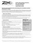
STāSIS Engineering
STāSIS Motorsport Suspension
Technical Specification and Installation Manual
Damper Model Information
Öhlins LMJ Series Damper: Öhlins’ LMJ stock car shock absorbers are based on the race
proven Öhlins 46HRC. A shock absorber featuring a large 46 mm piston for quick response,
a hose mounted (H) reservoir for better cooling and separate external rebound (R) and
compression (C) damping adjusters.
Features:
• Light weight, aluminum body.
• Large reservoir for better cooling.
• 2-way adjustable damping.
• Quick response for best handling.
• Optimum consistency on long runs.
• Easy to dial-in, reshim, rebuild and service.
2
Damper Technology – External Adjusters
Öhlins shock absorbers have a low speed compression adjustment knob located on top of
the reservoir. A low speed rebound adjuster is located at the end eye of the piston shaft.
The main bleed valve adjuster (rebound) is easy to access on the piston shaft just above the
eyelet. This adjuster is connected to the main bleed valve via an aluminum alloy rod that
runs inside the shaft. When the temperature inside the shock absorber increases, the rod
expands more than the shaft, further restricting oil flow through the main bleed valve. This
system helps prevent fading caused by loss of oil viscosity at higher temperatures. The
adjuster mainly affects low speed rebound damping, but has a slight affect on low speed
compression damping as well.
The temperature compensation system of the rebound adjuster reduces the number of clicks
when the shock absorber is hot. Therefore, always make changes from a previous click
position without closing the adjuster. To count the number of clicks you are using, first let the
shock absorber cool down to ambient temperature.
Damper Adjustments – FRONT AND REAR REBOUND
Adjustable REBOUND Damping: Damping is set with the knobs that have a normal right
hand thread. By turning them clockwise the damping action is increased, and by turning them
counter clockwise it is reduced. The knobs have definite positions with noticeable "clicks",
making it easy to count to the right setting.
The setting knob is located at the bottom on the piston rod (Fig. to the right). It can be
adjusted in about 40 steps. All adjusters have a normal right-hand thread. Click position
zero (0) is when the adjusters are turned clockwise to fully closed (maximum damping).
3
Damper Adjustments – FRONT COMPRESSION
Adjustable COMPRESSION Damping: The compression damping knob is located at the end
of the reservoir. This can be adjusted in about 25 steps.
The knobs have normal right hand thread. By turning clockwise it increases the damping
action and counter clockwise it reduces it. The knob will have definite positions with
noticeable "clicks", so it is easy to count to the right setting. All adjusters have a normal righthand thread. Click position zero (0) is when the adjusters are turned clockwise to fully closed
(maximum damping).
4
Damper Adjustments – STaSIS Settings
The following table represents the base settings for various conditions, fine tuning may be
required to reach the best setup given the users specific needs. All STaSIS Motor Sport
damper kits are delivered with the “Aggressive Street” setting.
AUDI B5 / C5
Performance
Street
Aggressive Street
Performance
Track
AUDI B6 / B7
Front
Shaft
12
Front
Reservoir
15
Rear
Shaft
24
Front
Shaft
12
Front
Reservoir
15
Rear
Shaft
26
8
10
16
8
10
16
5
5
10
5
5
12
5
Shock Absorber Technical Details – Compression and Rebound Strokes
Compression Stroke:
During a compression stroke, path 1, fig. 1 is
closed and the oil can only flow through
paths 2 and 3. The damping forces at
different compression speeds are
determined by the flow restrictions in these
paths.
The restriction of flow through path 2, fig. 1 is
determined by how much the oil pressure
can open the compression shims which are
closed shut whenever the pressure is too low
or the shock absorber is not in compression
stroke. These shims’ resistance to opening
are determined by their numbers, thickness
and diameters, and are carefully chosen to
give the optimum set-up. Path 3, fig. 1 is the
main bleed valve. The larger the valve
orifice, the more oil will flow through path 3
resulting in lower compression forces.
Rebound Stroke:
During a rebound stroke the oil flows in the
opposite direction. Path 2, fig. 2 is closed
and oil can only pass through paths 1 and 3.
Damping forces are determined by the flow
restrictions in paths 1 and 3. The flow
restriction through path 1 is determined by
how much oil pressure can open the
rebound shims which are shut closed
whenever pressure is too low or the shock
absorber is not in rebound stroke. Path 3,
fig. 2 is the main bleed valve. The larger the
orifice, the more oil flows through path 3,
making main valve rebound forces lower.
6
Shock Absorber Technical Details - Driving
Low Speed Compression and Rebound:
When driving on a smooth surface and the
shock absorber is compressed slowly
(turning g-loads), the damping oil is only
forced through the adjuster valve in the
piston shaft, fig. 1 flow 3.
The oil displaced by the piston shaft going
into the damper is forced through the
independent compression damping adjuster
out into the external reservoir, fig. 2 flow 3.
The floating piston in the reservoir is forced
to move, compressing the gas by the oil
displacement of the piston shaft.
When the shock absorber extends
(rebounds), the pressure behind the floating
piston forces the oil through a one-way
valve in the reservoir, and back into the
shock absorber body, fig. 4 flow 2 and 3.
The oil flow returning through the piston
follows the same path through the adjuster
valve, fig. 3 flow 3
High Speed Compression and Rebound:
When hitting a bump, the shock absorber is
compressed quickly (high shaft speed).The
pressure on the compression side increases
too fast for all of the oil to flow through the
adjuster valve and opens the shim stack
covering the orifices in the piston, fig. 1 flow
2.
As the quick increase in pressure reaches
the reservoir, a shim stack parallel to the
compression adjuster needle valve opens,
fig. 2 flow 1 and 2.
The floating piston is forced to move,
compressing the gas by the oil displacement
of the piston shaft.
When the shock absorber extends quickly,
the floating piston forces the oil through the
one-way valve back into the shock absorber
body, fig. 4 flow 2 and 3. The pressure
differential over the piston remains high and
the shim stack covering the rebound orifices
in the piston also opens allowing the oil to
return, fig. 3 flow 1.
7
8
Shock Absorber Technical Details – Damping Curves
At low shaft speeds the damping oil is
forced through and adjustable bleed
valve in the piston shaft. The valve
primarily controls rebound damping
and has only a minor affect on
compression damping.
The adjuster is connected via an
aluminum shaft that runs inside the
piston shaft. When the temperature in
the shock absorber increases, the
shaft extends and gradually closes the
bleed valve. This diminishes the
influence of oil viscosity changes due
to temperature, keeping the flow
through the valve virtually the same,
regardless of temperature.
Compression damping can be
adjusted using the second adjustable
bleed valve (located on the top of the
reservoir). The valve restricts flow to
the reservoir, not from it, thereby
influencing the compression damping.
At higher shaft speeds, damping
forces are primarily controlled by the
main piston and its compression and
rebound shim stacks. By changing
the number, diameter and thickness of
the shims in the stack, and by using
different jets in the valves, STaSIS
has customized the dampers to suit
your vehicle.
*All images and technical content are used courtesy of Öhlins.
9
STaSIS Motorsport and Signature Line Suspension Limited Warranty
Limited Warranty
Stasis Engineering warrants its line of Ohlins based Motorsport and Signature Line suspension kits against
manufacturing and material defects for the lifetime of its operation to the original retail purchaser (referred to as
“consumer” herein). This warranty cannot be transferred to another individual or entity and is limited to the
following listed terms and conditions•
•
•
•
•
•
•
•
•
•
•
Included Warranty Card must be returned after installation for warranty terms to be in effect. If no
warranty card is on file for the consumer requesting the warranty, all terms will be null and void.
Lifetime warranty covers all parts against manufacturing, material, and workmanship defects.
Corrosion damage due to environmental conditions is not covered under the lifetime warranty. STaSIS
Engineering highly recommends consumers coat the entire damper with a lubricant-protectant spray
after installation. STaSIS recommends using Boeshield T9 lubricant-protectant, a spray application
which forms a resilient waxy coating on the assembly after drying. This spray is available for purchase
directly from STaSIS or any Sears retail outlet.
Seal Heads are considered a high wear item and are not covered under the lifetime warranty after
installation and initial use.
To maintain the lifetime limited warranty policy, STaSIS Engineering requires an annual (1 year)
or 12,000 mile service interval for every Motorsport damper and a bi-annual (2 year) or 25,000
mile service interval for every Signature Line damper.
o
Consumers must schedule service directly with STaSIS Engineering, parts must be returned with a
STaSIS issued RMA number which is issued when scheduled.
o
Service consists of a complete overhaul of 2 front and 2 rear dampers. Overhaul will include a
complete disassembly and inspection of all dampers, replacement of all seal heads, and fluid
change for all dampers. Cost to consumer - $399.00 plus any applicable shipping charges.
o
Consumer will be advised of any added costs from worn or damaged parts requiring replacement
before re-assembly.
Warranty requests for dampers that have not been serviced within the past 12 months (Motorsport) and
24 months (Signature Line), will incur an automatic service charge of $399.00.
Warranty will not cover any damaged component due to installation/removal damage, vehicle accident
damage, incidental debris or rock contact, and/or curb impact.
Wear items – damper shafts, damper bodies, damper pistons, shims, glide rings, and end-eyes will be
covered under warranty for wear and tear for a maximum of 4 years from the date of purchase,
providing all annual service requirements have been met.
STaSIS Engineering reserves the right to make changes to the design of the assembly without
assuming any obligation to modify or update any products previously manufactured.
All warranty and service claims will be completed on a first come first serve basis. Claims will be turned
around in a maximum of 3 business days with the exception of parts non-availability.
Warranty will be honored based on the evaluation and the discretion of STaSIS Engineering. All
warranty requests honored by STaSIS will include all return shipping costs at the calculated ground
shipping rate. If expedite service is requested, customer must cover the cost difference.
INDEMNIFICATIONS: Customer agrees to indemnify, hold harmless STaSIS, the STaSIS authorized
dealership, and Audi of America against any and all claims, actions, and damages including injuries to persons
and/or death or disease arising or alleged to arise, in whole or in part due to the performance enhancement of
the vehicle.
10
STaSIS Motorsport and Signature Line Suspension Limited Warranty
EXCLUSIONS: STaSIS only warrants parts sold in, and installed on, automobiles built to United States and
Canada specifications. “Defects in material and workmanship” shall not include the effects of normal wear and
tear of a part installed on a performance-enhanced automobile.
This Limited Warranty is void if STaSIS or its designated representative determines that the STaSIS part has
been subjected to alteration, neglect, misuse or abuse; if any repairs have been attempted by anyone other than
STaSIS or its designated representative; or if failure is cause by accident, acts of God or other causes beyond
the control of STaSIS. Neglect, misuse and abuse include any installation, operation or maintenance of the
automobile or part not in conformity with the instructions contained in the documentation provided with the
automobile and part or otherwise available from automobile manufacturer or STaSIS.
LIMITATIONS: No agent, dealer, distributor, service company or other party is authorized to change, modify or
extend the terms of this Limited Warranty in any manner whatsoever.
DISCLAIMERS: STaSIS and its representatives shall not be liable for any injury, loss, cost or other damage,
whether incidental or consequential, arising out of any defect covered by this Limited Warranty, including,
without limitation, towing charges, rental car fees, labor for installation and removal of the product(s), loss of use
of the automobile while it is being repaired, or damages resulting from the enhanced performance of the
automobile, even if STaSIS has been advised of the possibility of such damage. The liability for materials and
workmanship of STaSIS under this Limited Warranty, if any, shall not exceed the sum of the original amount
paid for the defective product and the MSRP of all OEM parts for which the product directly affects. These
disclaimers shall be equally applicable to any service provided by STaSIS or its designated representatives.
LEGAL RIGHTS: This Limited Warranty gives purchasers of STaSIS parts specific legal rights.
Purchasers/consumers may have other rights which vary from state to state. Some states do not allow
limitations on how long an implied warranty lasts, so this limitation may not apply.
11
STaSIS Engineering B6 B7 MotorSport Suspension
MS Suspension Kit
Parts List
Qty
Description
2
2
Ohlins LMJ Damper Remote Reservoir
Ohlins Rear LMJ Damper internal
reservoir
Canister Mounting Brackets
Front shock clevis
Front Upper Stud
M12 X 1.25 Nylock
10” x 2.5” Springs
6” x 2.25” Springs
Rear Upper Stud
Lower Spring Perch
Spacers, Rear Lower Long
Spacers, Rear Lower Short
DRC Line Caps (RS4 Only)
UHWMPE Spacer, 2.25”
Perch Wrench
2
2
2
2
2
2
2
2
2
2
4
2
2
Part Number
SA02.2003.00
SA02.2004.00
SA01.3016.00
SA02.3110.00
SA02.3102.01
HA03.0107.00
SA02.3102.00
SA01.3008.00
SA02.3103.00
SA02.3105.00
SA10.0001.00
SA01.3001.00
Special Tools Required
Qty
1
1
1
1
1
1
1
1
Description
Part Number
Torque Wrench
Torque Wrench
Engine/transmission jack
Spring Compressor
Spring holder
Spreader
Pliers
Tensioning strap
VAG 1331
VAG 1332
VAG 1383 A
VAG 1752/1
VAG 1752/7
3424
T40067
T10038
12
B6 B7 MS Suspension Installation Instructions
Please read ALL instructions prior to attempting installation. Please torque all fasteners to
specifications.
Torque Values
Front damper to upper mount
Front damper upper mount to body
Front lower clevis to lower link
Front upper link pinch bolt
Front sway bar link to lower control arm
Front sway bar link to sway bar
Lower spring perch set screw
Rear damper to upper mount
Rear damper upper mount to body
Rear damper eye to lower control arm
Rear subframe assembly to chassis
OEM wheel bolts
* Must be tightened with vehicle at or near ride height.
Ride Heights
Recommended Front perch setting
Recommended Rear Perch Setting
9 ⅝” installed spring height
(600 lb spring)
2.25” bottom of perch to spring seat
(1000 lb spring)
For higher spring rates:
Front - add 1/8” (0.125”) for every 100lb increase to the spring rate.
Rear – subtract 1/8” (0.125”) for every 100lb increase to the spring rate.
13
37 ft-lbs
56 ft-lbs
66 ft-lbs*
29 ft-lbs
30 ft-lbs +
¼ turn
30 ft-lbs +
¼ turn
10 in-lbs
20 ft-lbs
26 ft-lbs
85 ft-lbs
65 ft-lbs
89 ft-lbs
Front Removal
1
Before removing any parts, park the car on a secure, stable, and level surface. Remove wheel trim; pull
trim cap off light-alloy wheels (using puller in vehicle tool kit) and loosen (but do not remove) the wheel lug
nuts. Jack the vehicle up, and place the car on four stable jack stands or use a professional vehicle lift. We
recommend having two people available for certain steps of the installation.
2
Remove wheels
3
Before removing left suspension strut,
remove headlight range control link from
track control link.
3a
RS4 Only:
Remove DRC fittings and cap with
STaSIS supplied line caps, front and rear
(total qty. 4).
4
Remove and discard spring clip – 1 – on
the underside of the suspension top plate
(this can be done with a pair of side
cutters and/or prying it off with a
screwdriver -remove lower shock clevis
bolt.
Remove upper ball joint pinch bolt – 2 –
and remove ball joints from upright (light
tapping with a mallet may be required to
free ball joint studs).
14
5
Unscrew hex bolt – arrow – connecting
OE damper fork to lower control arm.
6
Perform steps 2 - 5 on both sides of the
car and then open the front hood to
complete steps 7 – 9.
7
Unclip plenum chamber cover – 5 – and
remove it.
15
8
In the engine bay,
• remove rearward hood seal and rain
tray
• remove retaining screw for coolant
reservoir, lift coolant reservoir out of
mounting tabs at rear of tank and move
slightly to the side. Disconnect level
sensor plug from bottom of tank.
9
Remove the suspension top plate
mounting bolts – 1 – (three on each side).
Remove shock/spring/top plate assembly
from vehicle.
The following steps can be completed
with the front dampers off of the car.
16
10
Remove OEM damper and spring from
upper mount.
Use an adequate spring compressor to
compress spring on shock assembly.
VAG tools are pictured here. You may
also use a deep socket and vice-grips
with a hex key holding the shaft in place.
Note: You will not reuse the OEM
bumpstop, the thick washer, and the
nylock nut that sits on top of the damper
shaft.
11
Remove shock shaft nut and separate
shock and spring from top plate and
rubber isolation mount.
The following parts will be transferred to
the new damper:
#2 Shock Strut Mount
#4 Upper Suspension Mount
17
12
Remove swaged aluminum upper spring
seat retainer. Use a small chisel and
hammer to bend over swaged lip.
13
Place stud mount of the Stasis/Ohlins
damper through the opening in the center
of the suspension top mount plate.
18
14
Place rubber isolation mount on stud of
the Stasis/Ohlins Damper and secure with
the new M12x1.25 nut.
The top plate will be loose on the damper
assembly. This is normal; it will be
secured when bolted into the chassis.
CAUTION – DO NOT grab damper shaft
with any tools while tightening the nylock
nut.
15
Installation is the reverse of removal.
Note: Bonded rubber suspension
bushings can only be turned to a limited
extent. All mounting bolts of the
suspension links must only be tightened
when the suspension is compressed to
the curb weight position.
Canister Installation
Banjo bolt torque: 12ft-lbs
NOTE: these are basic
recommendations meant to
ease installation. Final
installation and mounting
location is at customer's
discretion
Things to remember:
•
Mount canisters and tethers
away from heat sources like
exhaust and turbochargers
•
Protect tethers against
chaffing / rubbing against
other surfaces
•
DO NOT loosen banjo fitting
on damper or canister, doing
so can will cause poor or
irregular performance
•
Make sure that the adjuster on
the canister is easily
accessible when choosing a
canister mounting location
•
Wrap canisters with tape
during installation to prevent
19
scratches/damage
16
Loosen plastic steering arm surround.
Pass canister through plastic steering arm
surround and through the steering arm
opening in the chassis.
RS4 Only
Remove left and right inner CV grease /
heat shield (this will provide additional
working room when trying to pass
canisters in to engine bay).
Remove airbox cover (2 screws at top of
airbox, MAF sensor plug, intake boot
hose clamp and vent hose clip)
20
Remove left and right, outer most steering
rack heat shield screws.
17
Carefully pull the canister through and
bring up to the top of the firewall to
mount.
NOTE: Two people may ease canister
installation.
18
Cannisters are attached to chassis using
the 8mm socket head bolts that attach OE
chassis stiffening bar. using supplied
STaSIS Ohlins canister mounts and
brackets,
Adequate slots will need to be cut in
engine bay firewall to allow damper hoses
to pass to adjacent side of firewall.
Take care to remove all sharp edges that
may damage damper hoses and / or
fittings.
21
Passenger Side
Drivers Side
19
Cabin air filter cover will need to be
trimmed as shown to provide canister
clearance.
22
Rear Removal
1
Securely support both rear corners
of the car, relieving tension on the
swaybar.
2
Remove wheels
If you have the factory spring
tensioner and spring holder (VAG
1752/1 and VAG 1752/16) then
move directly to Step 6 (and ignore
Step 13).
3
4
If you do not have the above tools
then complete Steps 3 – 5 and skip
Step 6.
Support rear subframe assembly as
shown
Remove rear subframe bolts, one
side only.
CAUTION! Only remove subframe
bolts one side at a time, make
sure two are securely retaining
subframe at all times
23
5
Gently lower rear subframe
assembly with jack.
CAUTION: if subframe is lowered
too far damage to brake line may
occur.
Remove rear spring and lower
spring seat isolator.
6
Insert spring tensioner VAG 1752/1
with spring holder VAG 1752/16 in
coil spring.
If necessary, insert spring holder in
individual windings and then screw
in place with spring tensioner.
Take care not to damage
trapezoidal link while doing this.
*Note* four windings must be
tensioned.
24
7
Remove nut – 1 – and
corresponding bolt.
8
Remove fender liner retaining
screws around damper to access
upper damper mounting bolts.
Remove bolts – 2 – (above
diagram).
25
9
Remove hex nut – 1 – from upper
damper mount, separate damper.
Save hex nut – 1 – and upper
damper mount – 2 – for
reassembly.
10
Assemble new rear damper into
mount as shown.
26
11
Install new Ohlins rear damper
assembly into vehicle.
(note the spacers for the lower
damper mounts are offset, the
longer of the two bushing will fit into
the register on the suspension
upright).
CAUTION! it is important to
loosen and re-torque the
lower fastener (#1) with the
suspension at final ride
height to avoid premature
bushing failure.
27
12
Install Stasis adjustable spring seat
and white spring isolator
Tighten the three grub screws on
the Stasis lower spring perch using
a 3mm hex key.
Failure to tighten these screws may
cause difficulty adjusting ride height
Place rear 2.25" spring with OEM
upper rubber isolator onto STaSIS
adjustable perch.
Perch is set to recommended height
prior to shipping.
13
Slowly raise subframe and reinstall
subframe bolts. Thread subframe
bolts by hand for the first few turns
to avoid cross-threading.
28
STaSIS Ohlins Ride Height Adjustment
Ride height inspection and adjustment procedure:
1.
After completing installation of the kit, set the vehicle on the ground and drive the car around the block
to settle the suspension. To take ride height measurements MAKE SURE THE VEHICLE IS PARKED
ON A LEVEL SURFACE. VERY IMPORTANT!
2.
Measure the ride height of the vehicle at four points for future reference. Measure from the center of the
wheels to the bottom of the fender lip.
3.
If you are pleased with this ride height, save the measurements for future reference. Make sure the
vehicle does not have a positive rake (measured from the front and rear of the door sills to the ground,
not the measurement in step 2), vehicles should be level. If ride height changes are required, continue
to step 4.
4.
Calculate the difference between the actual ride height and the ride height you would like the car to sit
at for the right front wheel. For optimum handling we recommend this be done with the driver in the car
and ¾ of a tank of fuel. We recommend that the distance between the center of the wheels and the
bottom of the fender lip is not set below 13.0 inches. The suspension is operating too close to its
maximum bump travel and handling can be negatively impacted.
5.
For most Audi vehicles, the ratio between the front shock body motion and wheel motion is about 0.65
to 1 and the rear is 0.80 to 1. This means that the wheel travels about 1 inch for every 0.65 inches of
shock body travel on the front and 0.80 inches of spring travel on the rear. Therefore, for example, if
you wanted to lower the car ½ inch from its current ride height at the right front wheel, then you would
have to lower the lower spring perch on the right front shock body by ½ x 0.65 = 0.32 inches. The rear
motion ratio is calculated the same way.
6.
The thread for both the front and rear spring perches is 1.5mm (0.06 in) per 1 rotation. Repeat the
calculation steps 4 & 5 for all four wheels.
7.
Armed with the data from steps 4,5 & 6, securely jack the car up and place it on four jack stands.
Remove the wheels if necessary to reach the lower spring perches. For the front dampers, loosen the
lower perch lock ring and thread the lower perch up or down by the amount you have calculated in step
5. The rear spring perch does require a locking ring and can be turned freely. For B6 and newer
chassis models, the rear spring perch can be difficult to turn. To ease spring pressure on the perch we
recommend loosening the two subframe bolts to lower the subframe assembly on each side (DO NOT
loosen all 4 subframe mounting bolts at once as this will affect wheel alignment). Record the location of
the perches so you can have it as a future reference if needed. Once the desired height is attained,
lightly tighten until snug all locking perches against the spring perch (do not overtighten or rings will be
difficult to adjust in the future).
8.
Place the wheels back on the car and lower it to the ground. The vehicle will sit high, you must drive the
car around the block before any measurements are taken. Go to step 2, make sure the car is in the
exact same location as before and press up and down on the car 3 or 4 times at each of the four wheels
to settle the suspension before you make any measurements. After you are completed with ride height
adjustments a 4-wheel vehicle alignment is highly recommended.
29
STaSIS Ohlins Maintenance Instructions
Custom Valved Ohlins Threaded Steel Dampers
The STASIS Coil Over kit is designed to provide superior service for the lifetime of your vehicle. As this
suspension system is a race car derived kit with high performance components, routine maintenance is required
to insure the optimal operation of your suspension system.
We recommend the following steps are performed annually, preferably before and after the winter season.
Vehicles that are exposed to more abusive environments, such as sea salt, road salt or dirt roads may
necessitate more frequent maintenance.
1.
Securely support the vehicle on four jack stands and remove the road wheels.
2.
Clean the threaded portion of the damper with a non metallic brush using soap and water.
3.
We recommend lowering or raising the lower spring perch to allow access to clean the
threaded portion of the damper that is covered by the perches.
4.
Lubricate the threaded portion of the damper with “Boeshield T9” lubricant-protectant or a
similar wax based lubricant.
5.
Return the perches to their original location and lightly tighten the locking perches. Spray
protectant on the remaining components of the damper assembly.
6.
Check the rear spherical bearings and verify that they are properly lubricated.
7.
We recommend servicing your dampers with STaSIS every year to maintain product
warranty and optimal functionality.
8.
If you have any questions about this, please call STaSIS at 888-9STaSIS.
Secure the road wheels and return the vehicle to the ground. Watch that the springs seat properly on the spring
perches
30