1
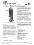
Argent Data Systems
Tracker2 model OT2m
User’s Manual
Revised 8-2-2008
Argent Data Systems
PO Box 579
Santa Maria, CA 93455
(800) 274-4076
Fax (866) 302-6890
www.argentdata.com
Copyright © 2007-2008 Argent Data Systems
All Rights Reserved
APRS® is a registered trademark of Bob Bruninga, WB4APR
FCC Part 15 Notice
This device complies with Part 15 of the FCC Rules Operation is subject
to the following two conditions: this device may not cause harmful
interference, and (2) this device must accept any interference
received, including interference that may cause undesired operation.
This equipment has been tested and found to comply with the limits
for a Class B Digital Device, pursuant to part 15 of the FCC Rules.
These limits are designed to provide reasonable protection against
harmful interference in a residential installation. This equipment
generates, uses, and can radiate radio frequency energy and, if not
installed and used in accordance with the instructions, may cause
harmful interference to radio communication. However, there is no
grantee that interference will not occur in a particular installation. If
this equipment does cause harmful interference to radio or television
reception, which can be determined by tuning the equipment off and
on, the user is encouraged to try to correct the interference by one or
more of the following measures:
-Reorient or relocate the receiving antenna.
-Increase the separation between the equipment and receiver.
-Connect the equipment into an outlet on a circuit different from that
to which the receiver is connected.
-Consult the dealer or an experienced radio/TV technician for help.
CE Declaration
This device complies with the essential protection requirements of the
European Parliament and of the Council Directive 2004/108/EC on the
approximation of the laws of the Member States relating to
electromagnetic compatibility. Assessment of compliance of the
product with the requirements relating to electromagnetic compatibility
was based on the following standards:
EN
EN
EN
EN
EN
55022 : 2006
61000 - 3 - 2 : 2006
61000 - 3 - 3 : 1995+A1 : 2001+A2 : 2005
55024 : 1998 + A1 : 2001+ A2 : 2003
61000-4-2 /-3 /-4 /-5 /-6 /-11
Introduction
The Tracker2 fills the gap between a traditional packet radio terminal node
controller (TNC) and a transmit‐only APRS™ tracker, and adds features not
found in either. While it may be used in KISS mode with a PC for general
purpose packet radio communications, its feature set is focused on APRS™
applications, including position reporting, messaging, and telemetry.
Firmware updates and enhancements are published frequently, so check the
Tracker2 website at http://www.argentdata.com/tracker2 to make sure you have
the latest firmware and documentation.
A Brief Overview of APRS
To understand the Tracker2 and how it can be used, it is important to first
understand exactly what APRS is.
APRS stands for Automatic Packet Reporting System. The name is a trademark
of its creator, Bob Bruninga, WB4APR. What the name refers to can be a subject
of considerable confusion to newcomers.
Primarily, APRS is a communications protocol. It defines how data (including
station and map object positions, weather information, radio direction finding
readings, text messages, and telemetry) can be communicated among packet
radio stations.
APRS can also refer to the network that carries this information. Throughout the
United States, Europe, and several other countries, a network of digital repeaters
(‘digipeaters’), usually on a common nationwide frequency, provides a transport
for APRS packets. Most APRS stations operate on one of these common
channels, but not all.
The APRS Internet System (APRS‐IS) is an Internet‐based adjunct to the radio
network. Internet gateways (IGates), often simply home PCs with an Internet
connection and a radio, pass traffic from the radio network to a shared,
worldwide APRS stream. Many IGates will pass at least text message traffic, and
sometimes other data, from the Internet back to the radio network. In this way,
text messages can be passed from one station to another even when a digipeater
path between the two doesn’t exist or isn’t reliable.
The name APRS is also sometimes used to refer to WB4APR’s original MS‐DOS
APRS mapping program, but it is now properly called APRSdos. Numerous
other mapping and messaging programs exist, using either the APRS radio
network, the APRS‐IS, or both. Some of these programs can function as IGates as
well.
Connected to the worldwide APRS‐IS stream are a number of database services.
These systems (findu.com and aprsworld.net are two of the most popular)
process and store all APRS traffic that finds its way to an IGate anywhere in the
world, and most provide maps, weather displays, and telemetry graphs based on
this traffic. This allows anyone with Internet access to monitor APRS data
without needing radio equipment of their own or special software.
Getting data to a web‐connected database isn’t the only thing APRS is good for,
of course. Depending on network coverage and load, it’s possible to
communicate over a range of hundreds of miles using the radio network alone.
However, being a shared network, reliability decreases with each added
digipeater hop. APRS is most reliable at the local level, and it’s rarely advisable
to use more than two or three digipeater hops. Often, a single hop is adequate
for local coverage.
The APRS protocol, hardware, and software can be used independently of the
national networks, as well. Local or temporary networks may be set up to cover
special events or to fill the needs of a particular organization. Some uses may not
require digipeaters at all – high altitude balloons, for example, often use APRS to
transmit position and telemetry data on a dedicated frequency directly to the
chase teams.
Mobile use of APRS can take a number of different forms. The simplest mobile
APRS setup is a transmit‐only tracker connected to a radio and GPS receiver.
These trackers generally have no receive capability, other than to check that the
channel is clear before transmitting. They allow the vehicle to be tracked by
others, but can’t receive messages or positions.
Another option is an APRS‐capable radio, like those sold by Kenwood. These
radios have a text display, but require a mapping GPS receiver to display the
positions of other stations.
An ordinary radio with a TNC can be used in conjunction with a laptop
computer or PDA to provide full APRS functionality, including mapping and
messaging, although this is usually the most expensive option and may not be
practical to operate while driving.
Where the Tracker2 Fits In
The Tracker2 has the capability to fill a number of roles in the APRS system. As
the name implies, it’s a tracker – it can format and transmit position data from a
GPS receiver. It also offers receive capability, though, and in a way that no other
device can currently match.
When it receives a position for a station or map object, the Tracker2 can create a
GPS waypoint for that position. On a mapping GPS receiver, this allows the user
to see the locations of other stations on the map, updated as each new position is
received.
While this concept isn’t new – APRS‐capable radios have been doing it for years
– the Tracker2 takes it a step further. While other devices output only a position
and name, the Tracker2 will, when used with a compatible Garmin or Magellan
GPS receiver, pick the most appropriate symbol for the waypoint (including
custom APRS symbols if available), extract the altitude, and insert the status text
(often including course and speed) into the waypoint details. For many
applications, this allows a GPS receiver to be used in place of a PC or PDA.
Aside from its tracking capabilities, the Tracker2 can also function as a
digipeater. Its remote control capabilities allow it to be reconfigured remotely,
and even through IGates, and its path limiting features let the sysop reduce the
amount of extraneous traffic carried by the network.
In KISS mode, the Tracker2 can also function as part of an IGate, when connected
to a PC with an Internet connection and appropriate software.
With few exceptions, the Tracker2 can perform all of its functions concurrently.
For example, a mountaintop installation could function simultaneously as a
digipeater, weather station, site monitor (reporting voltage and temperature),
and TNC for an IGate.
Major Features
APRS Tracker ‐ The Tracker2 is first and foremost a full‐featured APRS tracker.
It works with GPS receivers using either the industry‐standard NMEA format
($GPRMC, $GPGGA, and $GPGLL sentences) or the proprietary Garmin binary
protocol. In addition to transmitting its own position, it can also decode
incoming positions and plot them as waypoints on the screen of a GPS receiver,
selecting appropriate symbols and setting comment text and other waypoint
details if supported by the receiver.
KISS Mode ‐ The KISS protocol defines an interface between a TNC and its host,
typically a PC. This mode allows the Tracker2 to be used with PC‐based APRS
programs like Xastir, WinAPRS, and UI‐View32. It can also be used with non‐
APRS applications, subject to the limitations of the Tracker2’s transmit and
receive buffers.
Digipeater ‐ A digipeater acts as a simplex digital repeater, receiving packets
and retransmitting them, typically on the same radio channel. The Tracker2’s
digipeater function is designed specifically for APRS use, and supports advanced
features such as WIDEn‐N operation, hop count limiting, duplicate elimination,
preemptive digipeating, and multiple aliases.
Weather Station – The Tracker2 can be connected to several models of weather
station, including the Peet Bros. Ultimeter 2000 series, Dallas/AAG 1‐Wire
Weather Station, and LaCrosse WS‐2310 wireless weather station, to provide
remote weather telemetry.
Command Console – While the Tracker2 comes with a Windows‐based
configuration program, it can also be configured, tuned, and upgraded through a
traditional console interface with command syntax similar to that of the classic
TNC2 and its clones. Keyboard‐to‐keyboard QSOs are supported through a
‘converse’ mode as well as APRS messaging commands.
Power Control – The Tracker2 includes an integrated solid‐state relay that may
be used to control an external DC load. Typically, this is used to control power
to a transceiver to conserve power in applications like solar‐powered weather
stations; the radio can be automatically powered on just prior to a transmission,
and turned off again when the transmission is complete. The power output can
also be controlled manually through APRS messages.
Hardware Description
The Tracker2 model OT2m features a heavy‐duty steel enclosure and measures
approximately 4.2” by 3.2” by 1”. The circuit is built with surface mount
technology and includes over‐voltage and over‐current protection, as well as RFI
filtering on external connections.
Front Panel
The front panel has three indicator LEDs, marked ACT (activity), TX (transmit),
and RX (receive). The 6‐pin modular jack is an accessory port that provides a
Dallas 1‐wire data bus, 5 volt power, a counter/transmit trigger input, and a
profile select input.
Rear Panel
The rear panel has a female 9‐pin d‐sub connector for connection to a radio. A
male 9‐pin d‐sub connector provides, depending on software configuration, a
single RS‐232 port with hardware flow control or dual independent RS‐232 ports.
A standard 2.1x5.5mm center‐positive power connector accepts from 7 to 28
volts, and an access hole is provided to allow heavy gauge power cables to be
connected to the appropriate pads on the circuit board for control of an external
DC load.
Connections
SERIAL Connector
2:
3:
4:
5:
7:
8:
Data in (port A)
Data out (port A)
Power output for GPS
Ground
Data out (port B) or CTS
Data in (port B) or RTS
Note: The serial interface is configured as DTE (data terminal equipment) to
allow direct connection to a GPS receiver. Connection to a PC requires a null‐
modem cable.
RADIO Connector
1:
2:
3:
5:
6:
7:
8:
Audio out
COR / Squelch input
PTT out
Audio in
Ground
Power in
PTT in
ACCESSORY Connector
1:
2:
3:
4:
5:
6:
Counter / Transmit input
Ground
Ground
1‐Wire data bus
+5 Volt power output
Profile select input
Note: Pin 1 is the left‐most pin as seen from the front of the connector.
Jumper Settings
Voltage select – ‘5’. Connects pin 4 of the serial connector to
the output of the 5-volt regulator. Use this setting to supply
power to a 5-volt GPS receiver or other external device.
Voltage select – ‘12’. Connects pin 4 of the serial connector to
the input of the 5-volt regulator. Use this setting to supply
unregulated power from the radio connector to a GPS receiver,
or to supply power to the tracker from the serial connector.
‘EQ’ – Disables RX equalization when set.
‘HI’ – This jumper sets the audio output level to the high
range. This is needed mostly for mobile radios, especially
some commercial models.
‘HT’ – Selects if push-to-talk signaling through the audio
output line is enabled. Use this jumper with most HTs by
Icom, Yaesu, and Alinco handhelds, but not Kenwood.
Setup and Configuration
Once installed, you can use a PC to connect to the Tracker2 either the Windows
configuration program (otwincfg.exe) or a terminal emulation program of your
choice, such as HyperTerminal, SecureCRT, or Minicom.
To use the command console, connect at the proper baud rate (4800 baud is the
default) and press enter several times until you see a command prompt. To use
the Windows configuration program, simply start the program, select the COM
port, and power up the device.
The only setting absolutely required for normal APRS tracker operation is the
callsign. The defaults for all other settings should be reasonable, but you should
check on locally recommended settings, particularly for the digipeater path.
The EQ jumper controls the response of the audio input filter. Generally, the
jumper should be set when the audio source is ‘flat’ and not de‐emphasized, and
removed for most speaker connections. If you’re not sure which setting to use,
try both and see which works best for you.
Port Modes
The Tracker2 has two serial ports that share the same physical connector. A ‘Y’
adapter is available to separate the ports if needed. Both ports can operate in
multiple modes:
AUTO – In this mode, the device will automatically detect NMEA GPS data, Peet
Bros weather data, or (for port A only) command console input. Note that while
both ports can be configured in AUTO mode, only one should be used for a
given function at any time. For example, port A can accept NMEA data while
port B accepts weather data, but providing NMEA data to both ports
simultaneously will cause unpredictable operation.
GARMIN – This mode forces the selected port to 9600 baud, ignoring any
manual setting, and starts Garmin binary communications.
KISS – In KISS mode, a PC or other host device sends and receives raw AX.25
packets. Keep in mind that even with one or both ports in KISS mode, the
Tracker2 will continue to perform its other functions, including messaging and
digipeating. The host should use a different callsign/SSID combination to avoid
interference.
WS2300 – Supports LaCrosse WS‐2300 series weather stations at 2400 baud,
again ignoring manual baud rate settings.
FLOW – Valid only for port B, this setting causes the port B pins to function as
CTS/RTS flow control signals for port A.
Remote Access
Commands can be issued to the Tracker2 remotely via APRS messages. The
originating station’s callsign must appear in the device’s security authorization
list (see AUTHLIST command.) Commands are prefixed with ‘CMD’, and the
results of the command, if any, will be send back as an APRS message to the
sending station.
For example, ‘CMD VERSION’, sent from an APRS client, will cause the target
device to reply with its firmware version.
In response to a RESET command, the device will attempt to send one
acknowledgement before resetting. This is intended to prevent message retries
from causing multiple resets, but especially if the channel is busy there is a
possibility that the acknowledgement will not be sent before the reset is
executed. A RESET command should be cancelled after a few retries with no
response received to check if the device has indeed been reset.
Garmin Fleet Management Interface
Some Garmin navigation systems, including the nüvi 300 and 600 series and
StreetPilot 7000 series, provide a Fleet Management Interface (FMI) that can be
used with the Tracker2 with the proper cable.
To use the FMI features, set one of the Tracker2’s serial ports to GARMIN mode
and connect the FMI cable. The Tracker2 will automatically place the navigation
system in fleet management mode, which adds a ‘Dispatch’ menu item and may
change the layout of other menus. This mode change can only be reversed by
erasing all user data on the navigation system
If the waypoint output option is enabled, the Tracker2 will attempt to create
points of interest (POIs) on the navigation system for every station, object, or
item received. This feature is not part of the documented FMI protocol and does
not work properly on all devices; many will create duplicate POIs every time a
station moves. Until Garmin adds this feature to the official protocol, only the
nüvi 350 is known to display moving POIs properly.
Incoming APRS messages will display a message icon on the navigation system’s
screen and will be stored in the inbox. Outgoing messages can be addressed to a
specific station by starting the message with a dash (‘‐‘) and the destination
callsign, followed by a space and the message text. If no station is specified, the
message will be sent to the sender of the last message received. This allows
conversations to be carried on without having to constantly re‐enter callsigns.
To send a configuration command to the Tracker2, start a message with ‘‐‐’. For
example, ‘‐‐VERSION’ will cause the Tracker2 to respond with a message stating
its firmware version.
Command Reference
Most commands can be issued through the serial console, APRS message, or fleet
management message. Some commands make sense only when used from the
local console and are not available for remote access.
The Tracker2 will accept command abbreviations. A minimum of three
characters must be entered. For example, CALIBRATE can be entered as CAL.
AUTOBAUD can be entered as AUTOB, the additional characters being required
to distinguish it from AUTOSAVE.
1WIREWX
Enables 1‐Wire Weather Station mode. The TAI8515 weather station
should be connected to the front‐panel modular jack.
ABAUD 1200 | 2400 | 4800 | 9600 | 19200 | 38400 | 57600 | 115200
Sets baud rate for the primary serial port. Default is 4800 baud.
ALIAS <n> <callsign>
Sets digipeater alias for slot <n>, where n is between 1 and 8. This will
typically be a generic alias like ʹWIDEʹ. No SSID is allowed in this field.
ALTITUDE on|off
Report altitude in position packet.
AMODE AUTO | GARMIN | KISS | WS2300
Sets mode for primary serial port. See ‘Port Modes’ above for more
information.
AUTHLIST +/‐<callsign>
Displays or changes the list of callsigns authorized for remote access.
+callsign adds a callsign to the list, ‐callsign removes a callsign from the
list, and ʹnoneʹ erases the entire list. Up to six callsigns can be stored.
AUTOBAUD on|off
Enables automatic baud rate detection. When a baud rate mismatch is
detected, the unit will attempt to automatically select the proper baud
rate.
AUTOSAVE on|off
When enabled, the tracker will save its last‐known GPS position as a
permanent fixed position if the GPS fix is lost. This may be used in the
case of a temporary digipeater or weather station where a GPS receiver is
installed only during setup and is removed to conserve power. The
system must remain powered on for 30 seconds after GPS fix loss before
the position is saved.
BBAUD 1200 | 2400 | 4800 | 9600 | 19200 | 38400 | 57600 | 115200
Sets baud rate for the secondary serial port. Default is 4800 baud.
BEACON [text]
(local only)
If no beacon text is specified, a position beacon (and weather beacon, if
applicable) will be queued for immediate transmission. If a text string is
entered, that text will be transmitted as an AX.25 text packet.
BMODE AUTO | GARMIN | KISS | WS2300 | FLOW
Sets mode for secondary serial port. See ‘Port Modes’ above.
CALIBRATE LOW | HIGH | ALT | PACKET
(local only)
Calibration functions to set demodulator tuning and transmitter
deviation. ʹLowʹ transmits a 1200 hz tone, ʹhighʹ transmits a 2200 hz tone,
ʹaltʹ transmits alternating 1200 and 2200 hz tones, ʹpacketʹ sends a test
packet repeatedly, and ʹtuneʹ displays a tuning indicator for adjustment of
the demodulator. Use the ʹ[ʹ and ʹ]ʹ keys for coarse adjustment of the
transmit audio level, and ʹ‐ʹ and ʹ+ʹ for fine adjustment. Press any other
key to exit calibration mode.
CDINVERT on|off
Inverts carrier detect input polarity.
CLIMB on|off
Enables rate‐of‐climb indication. Climb rate is reported in feet per minute,
positive or negative, immediately following the altitude. Available only
in Garmin binary mode.
CNTRESET on|off
Causes counter to reset with each transmission. See accessory port
information.
COMMENT <string>
Sets beacon text / comment string, up to 64 characters.
COMPRESS on|off
Enables Base91 compressed format for position transmissions.
CONFIG 1|2
Selects configuration profile to modify.
(local only)
CONVERSE
(local only)
In converse mode, text entered at the console is transmitted when the
ENTER key is pressed. Hit CTRL‐C to exit. The command ‘K’ may also
be used to enter CONVERSE mode.
COUNTER on|off
Transmits counter value in status text.
CUSTSYM on|off
Enables the use of custom symbols if they have been uploaded to a
compatible Garmin GPS receiver (using the Garmin xImage utility).
CWBEACON <text>
Sends <text> as a Morse code beacon.
(local only)
DAO on|off
Enables transmission of the !DAO! extended‐precision construct. This
provides an extra digit of precision over the standard APRS position
format, but results in a longer packet and may not be supported by all
APRS clients.
DEVLIST
Lists addresses of all connected 1‐wire devices.
(local only)
DIGI on|off
When enabled, the tracker will digipeat packets having its own callsign
(MYCALL) in the next digipeater address field.
DIGIID <n> on|off
Enables callsign substitution for digipeater alias <n> (1 to 8). This should
normally be enabled.
DISPLAY
Lists all configuration parameters.
(local only)
DUMP
(local only)
Displays the tracker’s memory contents for troubleshooting purposes.
DUPETIME <0‐255> (seconds)
Sets digipeating duplicate suppression period.
EXTSQL on | off
Enables external squelch input.
FAHRENHT on|off
Reports temperatures in Fahrenheit when temperature output in the
status text is enabled.
GPSDATA on|off
Reports GPS quality data in status text: Horizontal dilution of precision
and number of satellites for NMEA mode, or estimated position error for
Garmin mode.
HBAUD 1200|300
Selects transmission baud rate. Note that the reception baud rate is fixed
at 1200 baud.
HEADERLN on|off
Breaks MONITOR packets into two lines, with header and payload
separated.
HOPLIMIT <n> <hops>
For digipeater alias <n> (1‐8), sets the maximum number of digipeater
hops allowed. This can be used to limit excessively long paths that may
cause network degradation.
INFO
Displays general system and diagnostic data, including number of packets
heard, packets digipeated, and frame check sequence errors detected.
INTERVAL <0‐65535> (seconds)
Sets the interval between automatic transmissions.
LOADFIRMW
(local only)
Loads firmware image using XMODEM protocol. The firmware file is
provided in a binary (.bin) format. The tracker will reset when the
firmware load is complete.
LVINHIBIT <0‐255> (* 0.0784 volts)
Sets the low‐voltage inhibit threshold. When the supply voltage drops
below this level, the unit will cease transmitting. Each unit is 0.0784 volts,
so a setting of 100 equals 7.84 volts.
MAXRANGE <0‐255> (miles)
When set to a non‐zero value, waypoints will only be created for stations
and objects within the specified range.
MONITOR on|off
Displays incoming packets on the console as they are received.
MYCALL <xxxxxx‐nn>
Sets the unitʹs callsign and optional SSID.
NICE <n>
When the tracker hears one of its own packets digipeated, it will skip the
following <n> transmissions. This allows a faster beacon rate to be used in
areas with poor coverage, without increasing the load on the network in
areas with better coverage.
OUTPUT1 on|off
Not currently implemented.
PATCH <hex string>
The patch command allows direct modification of the contents of the
Tracker2’s flash memory. This command should only be used as directed
by the manufacturer. Improper use of this command may render the
Tracker2 inoperable.
PATH <call1,call2,…>
Comma‐separated digipeater path list, containing up to three digipeater
addresses.
POSITION <hhmm.mmx hhhmm.mmx> | GPS
Sets fixed position or enable GPS. Position must be entered in degrees
and decimal minutes, including leading zeros. Setting position to ʹGPSʹ
reverts to GPS tracking mode.
Example: POSITION 4851.49N 00217.66E
POWER on|off|<0‐255> (seconds)
ON or OFF will manually set the state of the power output. Specifying a
value in seconds will enable automatic power control mode, where the
power output is turned on for the specified number of seconds prior to
transmission, and turned off immediately after transmission.
PREEMPT <n> on|off
Enables digipeater preemption for alias <n> (1‐8). If preemption is
enabled, packets will be digipeated on this alias even if it isnʹt the next
address in the packet’s digipeater list.
PROFILE 1 | 2
Selects the configuration profile to use.
PTTINPUT on|off
Enables PTT input for mic encoder opration. A position packet will be
transmitted when the mic PTT is released.
PULSE <0‐255> (seconds)
Activates power output for specified duration.
QUIET <0‐255>
Time channel must be free before transmission can occur, in 1/64 second
units.
REARM <0‐255> (milliseconds)
Specifies minimum time between counter inputs. May be used for switch
de‐bouncing.
REPLY <message>
(local only)
Sends a text message to the last person who sent a message addressed to
this unitʹs callsign
RETRIES <0‐255>
Number of times to retransmit an outgoing message.
RETRYTIME <0‐255> (seconds)
Time between message retry attempts ‐ interval increases by this value
with each transmission.
REQALL on|off
Require all configuration switch parameters to be met before switching
profiles.
RESET
Perform software reset. Saved settings are unaffected.
RING on|off
Sends a bell character whenever an incoming message arrives.
SEND <callsign> <message>
Sends a text message to the designated recipient.
(local only)
SHAREDPTT on|off
Controls PTT line behavior for mic encoder mode. If enabled, PTT output
is not asserted until the PTT input is released.
SLOT <0‐65535>
Time slot for transmission (if TIMESLOT is on). Slot position is counted in
seconds from the start of the hour.
SMARTBCON <low speed> <high speed> <low rate> <angle> <time>
Configures SmartBeaconing. The SmartBeaconing algorithm allows the
tracker to operate more efficiently by changing how often it transmits depending
on its speed and turn rate.
When stopped or moving at a speed below the low speed setting, the tracker will
transmit at a fixed rate determined by the lower rate setting. Above the specified
high-speed threshold, the higher rate setting is used. Between these two extremes,
the interval varies between the low rate and high rate (specified separately with
the INTERVAL command) depending on the speed.
The <low speed> and <high speed> settings define these two limits. For storage
efficiency, the speeds are represented in units of 32 centimeters/second. To
convert from miles per hour, multiply by 1.397. To convert from kilometers per
hour, divide by 1.152.
Setting
5
10
15
25
40
60
80
100
MPH
3.6
7.2
10.7
17.9
28.6
43
57
71
Km/h
5.7
11.5
17
29
46
69
92
115
<low rate> and <high rate> are specified in seconds. <angle> indicates the
change of direction, in degrees, that will cause an immediate transmission.
<time> specifies, in seconds, the minimum time required between transmissions,
regardless of speed or turns.
SQUAWK <0‐255> (seconds)
Transmits alternating tones for specified number of seconds. May be used
for testing or direction finding.
SWDCD on|off
ON selects software data carrier detect mode, providing a channel busy
indication only when data is present. OFF selects energy detect mode,
which will provide a busy indication for any signal, including static or
voice. Use the ON setting for digipeater operation with open squelch for
fastest signal acquisition.
STATUS <0‐255>
Status packets are sent every n transmissions, or if set to 0, status text is
sent as part of the position packet.
SYMBOL <1‐2 characters>
APRS symbol character, optionally preceded by symbol table or overlay
identifier.
TELEMETRY on|off
Enables transmission of telemetry packets.
TEMP on|off
Enables transmission of temperature readings from the on‐board
temperature sensor.
TEMPADJ <‐128 to 127> (degrees C)
Offset for temperature sensor in degrees C.
TIMEHMS on|off
Sets timestamp mode to hour/minute/second when enabled. Default is
day/hour/minute. Applies only to NMEA mode – hour/minute/second
format is always used in Garmin binary mode.
TIMESLOT on|off
Force position packets to be transmitted only in designated time slots,
expressed as the number of seconds from the start of the hour to the first
transmission.
TIMESTAMP on|off
Report time information in the position packet.
TXDELAY <0‐255>
Delay between start of transmission and start of data. This setting should
be set to the minimum value that allows reliable reception of transmitted
packets. An excessively high TXDELAY setting wastes channel capacity.
Each unit is one character time – 1/150 second at 1200 baud.
TXLEVEL <1‐255>
Sets transmission audio level. This value should be selected to provide an
appropriate FM deviation level, typically about 3.5 kHz.
TXNOFIX on|off
Allows transmission of last position if GPS fix is lost for more than 30
seconds. Default behavior is to cease transmitting the position in the
absence of a valid GPS signal.
TXONCHG on|off
Causes an immediate transmission when switching configuration profiles.
USEALIAS <n> on|off
Enables digipeating for alias n.
VELOCITY on|off
Enables transmission of velocity (course and speed) information in the
position packet.
VERSION
Displays firmware version number.
VOLTAGE on|off
Enables reporting of supply voltage in status text.
WAYPOINTS on|off
Enables output of waypoints from received positions.
WPTLEN <6‐9>
Sets maximum waypoint name length.
WXINFO
Displays weather information from attached station.
UI-View32 Setup
For use with the UI‐View32 APRS client, either port of the Tracker2 can be set
manually to KISS mode. No configuration commands are needed in UI‐View32
once this has been accomplished.
In this example, port A has been set to KISS mode at 9600 baud using the tracker
configuration utility. The console commands AMODE KISS and ABAUD 9600
produce the same result.
The baud rate selected in the UI‐View32 ‘Comms Setup’ screen must match the
rate selected for the port in use. Select host mode ‘KISS’, and be sure to choose
the correct COM port for your PC. Click on ‘Setup’ to continue configuration.
No ‘Into KISS’ or ‘Exit
KISS’ commands are
needed, and any settings
in these fields should be
deleted. Placing a ‘0’ in
the ‘Exit KISS’ field avoids
a bug in UI‐View32 that
prevents it from exiting
properly when the option
is left blank.
If you would prefer to have UI‐View32 automatically reconfigure the tracker for
KISS mode each time the program is started, use the following settings:
This configuration will
only work with port A, as
the command console is
not available on port B.
EQ Jumper and Input Filter Response
RX filter response, EQ jumper removed
RX filter response, EQ jumper installed