1
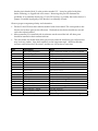
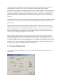
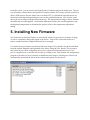
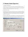
OpenTracker+
User’s Manual
1. Introduction
The OpenTracker+ is a simple, low‐cost amateur radio data encoder capable of generating 1200 or 300 baud AX.25 packets using the APRS™ protocol, as well as PSK31 text beacons. It can be connected to a GPS receiver to report position, course and speed, time, and altitude, or it can encode and transmit data from a supported weather station. It will also report telemetry from its onboard temperature and voltage sensors, and an external counter input can report a cumulative total of counter events or the number of events since last transmission.. With its expandability and ease of reprogramming, the device can be adapted to a wide variety of tasks. This new version of the OpenTracker improves on the original in several ways, including waypoint output capability, twice as much program space, three times as much RAM, and a simplified hardware design that provides more features while reducing complexity and part count. Acknowledgements The OpenTracker+ owes much to those that came before – in particular, John Hansen’s GPS‐E firmware and its TAPR PIC‐E hardware, Steve Bragg’s HamHUD, and Byon Garrabrant’s TinyTrak series. The SmartBeaconing™ algorithm used by the OpenTracker+ was originally developed by Tony Arnerich, KD7TA, and Steve Bragg, KA9MVA. Darryl Smith, VK2TDS, demonstrated waypoint output capability in his Anti‐Tracker design. APRS™ is a trademark of Bob Bruninga, WB4APR. Brian Riley, N1BQ, and Keri Morgret, N6TME, contributed to this manual. Table of Contents
1. Introduction ............................................................................................................................................ 2
2. OpenTracker+ Kit Assembly Notes ..................................................................................................... 4
Assembly Notes ..................................................................................................................................... 4
Jumper Functions................................................................................................................................... 6
3. Connector Pin Assignments ................................................................................................................. 7
Kit Assembly Pictorial....................................................................... Error! Bookmark not defined.
Finished kit ......................................................................................... Error! Bookmark not defined.
4. OpenTracker+ Setup and Operation ................................................................................................... 8
a. General ................................................................................................................................................ 8
b. Receive Adjustment .......................................................................................................................... 8
c. Transmit Adjustment ........................................................................................................................ 8
d. LED Blink Codes ............................................................................................................................... 9
e. Configuration Program..................................................................................................................... 9
f. Main configuration window........................................................................................................... 11
Configuration Profiles .................................................................................................................... 11
Loading and Saving Settings ......................................................................................................... 11
Basic Configuration Options.......................................................................................................... 12
5. Installing New Firmware .................................................................................................................... 18
6. Weather Station Operation ................................................................................................................. 19
7. Telemetry Operation............................................................................................................................ 20
8. OpenTracker Circuit Details............................................................................................................... 21
Theory of Operation ............................................................................................................................ 22
Appendix A – Test Procedures .............................................................................................................. 24
Measurements ...................................................................................................................................... 24
Appendix B – APRS symbol tables........................................................................................................ 25
2. OpenTracker+ Kit Assembly Notes
If you purchased an assembled unit, you may wish to skip ahead to the section on jumper settings and connections. The OpenTracker+ kit requires basic to intermediate level soldering skills. You will need a low‐
wattage soldering iron, wire cutters, and solder. Rosin core solder is recommended – never use acid core solder for electronics. Review the parts list and identify the components you received. If any are missing or damaged, contact [email protected] for replacements. Don’t worry if your kit includes extra resistors or other parts not listed above – these are provided for modifications and alternate versions of the kit. Assembly Notes
1. The order in which the components are installed is not critical. However, you may wish to install connectors X1 and X2 after nearby parts (D1, D2, and C1 in particular) have been installed. Don’t put your fingers directly under the connectors when pushing them on to the board; they can snap into place suddenly and poke you. 2. Solder the socket for U3 carefully. Avoid excess solder that may form bridges between the closely spaced pins. If you plan to solder the resistors from the top side of the board (this can save time, especially if you’re holding the board in a vice) install the socket after soldering the resistors to avoid damaging it. 3. Install the LED last. Insert it without soldering it, with its shortest lead toward the edge of the board and the D3 marking. Place the circuit board in the top half of the case, and push the LED into its mounting hole from the back. Solder it in place and trim the leads. 4. If the unit will not be powered through the serial connector, and will not be providing unregulated power to another device through the serial connector, consider removing the header pin in header block J1 at the position marked ‘12’. It may be pulled with pliers before soldering, or clipped with wire cutters. Removing this pin will eliminate the possibility of accidentally destroying a 5‐volt GPS receiver, or possibly the tracker itself, if a jumper is installed improperly or the header is accidentally shorted. Observe proper component polarity and orientation: •
•
•
Diodes D1 and D2 have their cathodes marked with a black band. This corresponds to the line shown for these parts on the silkscreen. The bands on the diodes should face toward each other when installed. Microcontroller U3 is installed with its reference notch toward the left. All other parts should be installed as their outlines indicate. The color bands for the 680 ohm (blue‐gray‐brown) and 6.8k ohm (blue‐gray‐red) resistors may look very similar. Note their sequence on the component tape – the three 680 ohm resistors come before the 2.2k resistor, and the two 6.8k resistors come after. Part
Description
Notes
U1 U2 U3 R1, R8 R2,R5,R10,R11 R3, R7 R4 R6 R9 R12, R13, R14 JP1 C1,C2,C3,C6 C4, C5 Q1, Q2 D1, D2 D3 X1 X2 Y1 7805 Voltage Regulator LM335Z temperature sensor MC908JL16CSPE Microcontroller 27 K resistor 10K resistor 6.8K resistor 10M resistor 2.2K resistor 240K resistor 680 ohm resistor 12‐pin header 0.1uF capacitor 18pF capacitor 2N7000 transistor 1N4148 diode Dual‐Color LED DB9 Connector – female DB9 Connector – male 29.4912 MHz crystal Align to silkscreen outline. No screw is required. Align to silkscreen outline Reference notch faces left Red‐Purple‐Orange Brown‐Black‐Orange Blue‐Gray‐Red Brown‐Black‐Blue Red‐Red‐Red Red‐Yellow‐Yellow Blue‐Gray‐Brown Yellow with “104” marking “180j” or “180” marking Align to silkscreen outline Black band denotes cathode Shortest lead faces edge of board Left edge of board Right edge of board Bend down parallel to PCB before soldering Jumper Functions
The 12‐pin header, J1, provides several jumper‐selectable functions. ‘HI’ – This jumper sets the audio output level to the high range. This is needed mostly for mobile radios, especially some commercial models. ‘HT’ – Selects if push‐to‐talk signaling through the audio output line is enabled. Use this jumper with most HTs by Icom, Yaesu, and Alinco handhelds, but not Kenwood. Voltage select – ‘5’. Connects pin 4 of the serial connector to the output of the 5‐volt regulator. Use this setting to supply power to a 5‐volt GPS receiver or other external device. Voltage select – ‘12’. Connects pin 4 of the serial connector to the input of the 5‐volt regulator. Use this setting to supply unregulated power from the radio connector to a GPS receiver, or to supply power to the tracker from the serial connector. 3. Connector Pin Assignments
Table 3 – DB9 Female (X1) – Radio Port Table 4 – DB9 Male (X2) – Serial Port Pin Function Pin Function 1 Audio Out 1 No Connection 2 COR / Squelch Input 2 Data In 3 PTT Output 3 Data Out 4 Counter / ‘Transmit Now’ input 4 Vext 5 Audio In 5 Ground 6 Ground 6 No Connection 7 Power in 7 1‐Wire Data Bus 8 PTT Input 8 No Connection 9 ADC5 input / Power relay 9 No Connection Special notes: X2 is wired as DTE to allow connection to a GPS receiver using a standard cable. A null modem cable is required for connection to a computer. When wiring your own null modem cable, swap pins 2 and 3 (pin 2 on the PC connects to pin 3 on the tracker and vice versa) and wire pin 5 straight through. No other connections are required for programming. COR / Squelch input: This input is active high unless the ‘Invert CD’ option is selected in software. Do not exceed 5 volts at this input. Counter / Transmit Now: The function of this input depends on whether the counter option is enabled. If the counter is enabled, pulling this pin to ground increments the counter. Otherwise, grounding this pin causes an immediate transmission, assuming the tracker is in a state in which it can transmit. If this input is connected with a long cable or may be subjected to RFI, you may need to provide a stronger pull‐up to 5 volts. A 10k or 4.7k resistor is usually suitable. See also the ‘jumper’ setting in the profile switching menu for additional uses. PTT Input: Active low, used for mic encoder operation. 1‐Wire Data Bus: Bidirectional data interface using the Dallas Semiconductor 1‐Wire scheme. This is used primarily for interfacing with the Dallas / AAG TAI‐8515 weather station. It may also be used with standalone sensors such as the DS18S20. Data Out: This signal varies from 0 to 5 volts and is compatible with most RS‐232 devices. However, some GPS receivers and weather stations require a negative voltage to communicate properly and will require an external level shifter. 4. OpenTracker+ Setup and Operation
a. General
The following general steps are required to use your assembled OpenTracker+: • Build or obtain cable for connection to radio and power • Connect tracker to computer, radio, and power • Run configuration program to set callsign and audio level • Disconnect computer and connect GPS receiver or weather station The radio connector, X1, is similar to that used by the Kantronics KPC‐3 and the Byonics TinyTrak3. Any cable that was made to interface a radio to either of these devices should work with the OpenTracker+. Pre‐assembled cables may also be purchased from RPC Electronics at http://www.rpc‐electronics.com. Most handheld radios (with the notable exception of those made by Kenwood) assert PTT by grounding the microphone input through a resistor. The OpenTracker+ uses this method if the ‘HT’ jumper is installed. This jumper should be omitted when the tracker is used with mobile radios or with handhelds that do not use this method of PTT keying. The OpenTracker+ requires 6.7 to 28 volts DC. However, the maximum voltage that can be measured and reported by the tracker is 18.5 volts. Power may be supplied through either 9‐pin connector. Most often, it is supplied through pin 7 of the radio connector. It may also be supplied through pin 4 of the data connector if a jumper is installed in the ‘12’ position of the header marked ’12 ‐ 5’. b. Receive Adjustment
The OpenTracker+ can be set to detect any signal on its audio input (including voice, data, and static) or only valid data. The latter mode is referred to as Data Carrier Detect, or DCD. If DCD is enabled, the radio may be operated in open‐squelch mode, but the tracker will detect only data signals and not voice. All receive settings are made through the configuration program. c. Transmit Adjustment
The OpenTracker+ has two audio level ranges. The higher range is selected by installing a jumper in the ‘HI’ position on header block JP1. If you’re not sure which range your radio requires, start with the low range and install the jumper only if you’re unable to produce a suitable modulation level. The audio level may be fine‐tuned through the configuration program. The configuration program can also be used to transmit tones for calibration. If you have a deviation meter or service monitor available, set the transmit level to achieve a maximum deviation of about 3.2 kHz for VHF FM 1200 baud operation. If you aren’t able to directly measure the deviation, use another radio to listen to the transmitted audio. Increase the level slowly until the signal doesn’t get any louder, and then turn it back down until it gets noticeably quieter, and turn it down a few notches below that. Proper audio level is critical to ensuring the transmitted packets can be received and decoded. A transmit audio level set too high will cause clipping in the transmitter, which results in signals that are difficult or impossible to decode. d. LED Blink Codes
The tracker reports its status through the use of a multi‐color LED as follows: Action Meaning Rapid green blinking Channel is in use Single green flash Received valid GPS fix Double red flash Received invalid GPS fix. GPS may not be ready Solid red Transmitting or in configuration mode Single yellow flash A position was received and decoded e. Configuration Program
The OpenTracker+ is configured through a Microsoft Windows program available in the download section of the website. Use a standard null‐modem cable to connect the device to the PC. The PC does not supply power to the tracker, so it must be powered externally. Often, you can power the tracker through the radio cable as in normal operation. If this is not an option, a 9‐volt battery clip can be wired to a DB9 connector to provide sufficient power for programming. Connect the tracker and start the configuration program. The first window displayed allows you to select the COM port that the tracker is connected to. Overwriting an Invalid Configuration The ‘Erase device and load new firmware’ option will load a new firmware image, using the default configuration settings, without attempting to read the existing configuration first. This is particularly useful if the tracker has an invalid or missing configuration. Turbo Mode By default, the configuration program will attempt to connect at 115,200 baud. If you have trouble connecting, use the ‘Disable Turbo’ option to force the program to connect at 19,200 baud. Warm Boot vs. Cold Boot If the unit is already powered on and operating when you click the ‘Connect’ button, the program attempts a ‘warm boot’ operation to put the device into configuration mode. If the firmware has been corrupted, i.e. by a failed upgrade, it may fail to enter configuration mode. You can correct this by performing a ‘cold boot’ ‐ power the unit off and power it on again after clicking ‘Connect’. Working Offline If you need to edit a configuration without connecting the tracker, click the ‘Offline’ button. You will need to have a saved configuration file to work from. f. Main configuration window
Configuration Profiles The OpenTracker+ can store two separate configuration profiles. The profile currently being shown is selected using the tabs at the top of the window labeled ‘Profile 1’ and ‘Profile 2’. When it is first powered on, the OpenTracker+ will always start out using Profile 1. After startup, profile selection depends on the settings in the profile switching screen. To access these settings, click ‘Profile Switching’. See the section below on profile switch for more information. Loading and Saving Settings After changing any configuration options, you must click the ‘Write’ button to write the changes to the tracker’s firmware. You may also use the ‘Save to File’ button to save the configuration options to a file, which can be loaded later using the ‘Load from File’ button. Basic Configuration Options Callsign – The radio callsign to use when transmitting. Tactical callsigns may be used, but FCC and ITU rules require periodic identification. If the actual callsign is not used here, be sure to include it in the comment field. Baud Rate – For normal VHF operation this should be 1200. 300 baud is commonly used for HF. The OpenTracker+ uses mark and space frequencies of 1600 and 1800 hz respectively in 300 baud mode. Path – This specifies the digipeater path to use. Specific callsigns may be entered (e.g., ‘K6SYV‐10, K6TZ‐10’) but for APRS operation a set of common aliases are usually used. A suggested default path is ‘WIDE1‐1, WIDE2‐1’. It is rarely necessary to use a path greater than WIDE3‐3 (requesting three ‘wide’ digipeater hops), and excessive paths generate large amounts of traffic that degrade the performance of the network. If you’re not sure what path should be used for your local area, check with a local digipeater operator. This field may be left blank. Symbol Table and Symbol Code – These settings control the symbol used to indicate the station’s position when drawn on a map. See Appendix B for a listing of available symbols. Temp. Adjust – Calibration offset for onboard temperature sensor. The sensor used on the OpenTracker is fairly linear across its operating range and requires a single‐point calibration. The easiest way to accomplish this is to set a thermometer next to the tracker. Subtract the temperature reported by the tracker from the temperature shown by the thermometer, and enter that value in this field. For example, if the thermometer shows the temperature as 26°C and the tracker reports 29°C, enter –3 for the adjustment value. Quiet Time – This setting determines how long the channel must be clear before the tracker will transmit. Each unit is approximately 1/56 second. Setting the quiet time to zero causes the tracker to ignore detected traffic. Text – This is a freeform text field. Anything entered here will be displayed in the comment portion of the transmission or in a separate status packet, as selected. Keep comments as brief as possible to avoid wasting channel capacity, or use the ‘Every __ Transmissions’ option to reduce how often the text is sent. Altitude, Course/Speed, Time – When checked, report these values as indicated by the GPS receiver. The timestamp may be in Days/Hours/Minutes or Hours/Minutes/Seconds. DAO – Enables the proposed !DAO! APRS extension to provide the map datum used and an extra digit of latitude and longitude resolution. May not be supported by all APRS clients. The datum is always reported as WGS84, which is the standard for normal APRS operation. GPS Quality – Report number of satellites in use and horizontal dilution of precision information as reported by the GPS receiver. Temperature – Report temperature as indicated by the onboard temperature sensor in the comment field, in degrees C. Not affected by the Metric / English setting. Voltage – Report input voltage in the comment field. The maximum value is 18.5 volts, and the minimum is the dropout voltage of the regulator – typically 6.7 volts. Compressed – Enables Base91 compressed position reporting. This mode is widely, but not universally, supported. Packets in Base91 format are shorter than their uncompressed equivalents and provide greater position resolution. Telemetry every n – Sends a telemetry packet every n transmissions. See the telemetry section for more details. TX Interval – How often the tracker should transmit. Allowable values are 0 to 65,535 seconds. This setting will depend on your intended use. One transmission every two minutes is accept‐
able for most mobile stations. A fixed station (e.g., a solar powered site reporting battery voltage and temperature) might choose an interval in the range of 5 to 30 minutes. If you require transmissions more often than every two minutes or so, consider using the Smart‐
Beaconing™ options detailed below. Special events with many trackers and short transmission intervals should be operated on a separate frequency, not on the shared APRS channel. An interval of zero will disable timed transmissions. SmartBeaconing – Originally developed for the HamHUD by Tony Arnerich, KD7TA, and Steve Bragg, KA9MVA, the SmartBeaconing™ algorithm allows the tracker to operate more efficiently by changing how often it transmits depending on its speed and direction of travel. When stopped or moving at a speed below the low speed setting, the tracker will transmit at a fixed rate determined by the lower rate setting. Above the specified high‐speed threshold, the higher rate setting is used. Between these two extremes, the interval varies between the low and high rates depending on the speed. A turn angle can also be specified to cause the tracker to transmit when turning. The final setting ensures that the tracker will never transmit more often than the specified interval, regardless of speed and turn rate. This can be useful to avoid transmitting more than once in a long, shallow turn. Use PTT Input – When this checkbox is enabled, the tracker can be connected inline with a microphone to operate in burst‐after‐voice (mic encoder) mode. A packet will be transmitted whenever the microphone PTT is released. Timeslot – The timeslot option is typically used to coordinate multiple trackers, especially for special events where many transmitters will be sharing the same channel with a high beacon rate. The number entered selects the timeslot’s offset, in seconds, from the start of the hour. The tracker will transmit at this time, and every transmit interval after that. The timeslot value should be smaller than the transmit interval. As an example, two trackers could be configured with an interval of 10 seconds, with one tracker set to slot 0 and the other to slot 5. The first tracker would transmit at 12:00:00, 12:00:10, 12:00:20, and so on, while the second would transmit at 12:00:05, 12:00:15, and 12:00:20. Position – The tracker can operate in GPS or fixed position mode. When entering a fixed position, enter degrees in the first box and decimal minutes in the next box. Click on the buttons next to the coordinates to select North/South and East/West. Don’t require GPS fix – Normally, while in GPS mode, the tracker will not transmit without a valid fix. When this option is selected, the tracker will continue to transmit its last known position if GPS lock is lost for more than 30 seconds. This condition is indicated by the text ‘NOFIX’ in the status message. If the tracker has received no valid fix since startup, no position will be reported. Status text and telemetry packets will be unaffected. This option is particularly useful for applications like high altitude balloons that may lose GPS lock after landing, but still need to transmit to be found. Waypoint Output – Enabling the waypoint output option causes the tracker to parse received APRS positions and output them over the serial port at 4800 baud. Waypoints are provided in both NMEA 0183 format ($GPWPL sentence) and Magellan format ($PMGNWPL sentence). Length Limit – Some GPS receivers are not capable of display the full 9 characters required for APRS call signs and object names. Setting this option to a smaller number causes the tracker to intelligently truncate the name of the waypoint. Spaces and dashes are eliminated first, and if further truncation is required, characters are dropped from the left first. This prevents stations with different SSIDs from conflicting – for example, with a limit of 6 characters, KB6YUO‐12 and KB6YUO‐6 would be truncated as 6YUO12 and B6YUO6 respectively. Enable Counter – This checkbox enables the digital counter function. When this function is enabled, the tracker will no longer transmit immediately when X1 pin 4 is shorted to ground. Instead, it will increment a counter and include the current count in the status text, e.g., ‘CNT00001’. The maximum count is 65535, after which the counter rolls over to zero. This option can not be used concurrently with profile switching with the ‘jumper’ option. Reset on Transmit – Setting this checkbox causes the counter to reset with every transmission. Hence, the count reported is the number of events since the last transmission. Debounce – This is a delay applied to the counter input. After a counter event is registered, all subsequent events are ignored until the specified time has elapsed. Without a suitable debounce setting, a typical pushbutton could register several events for one press. Power Control – When selected, the tracker will assert a 5‐volt signal on X1 pin 9 before each transmission. This can be used to drive a relay or MOSFET to control power to the transmitter. The ST VN920 intelligent high‐side switch is an excellent choice for loads of several amps. The tracker will pause for the specified number of seconds to give the transmitter time to power up. The power control feature is especially useful for solar‐powered weather or telemetry stations. Do not exceed 15 mA load on the output pin, and be sure to protect it from inductive kickback if it drives an inductive load such as a relay coil. TX Audio Level – This slider sets the audio output level. This level can be set interactively from the Tuning/Diagnostics screen. If you find that the required level is less than one quarter of the full scale, make sure you have the ‘HI’ jumper removed. Running with the audio level set in software to a very low level can increase DAC quantization noise. TX Delay – All radios require a certain amount of time to stabilize on their transmitting frequency, and receivers also require time to lock on. This value specifies the number of milli‐
seconds the tracker should wait after the start of the transmission before it begins sending data. Allowable values are 0 to 1023 milliseconds. Setting this value too high will keep the channel busy longer than necessary. Setting it too low will prevent packets from being transmitted properly. Finding the optimum value for your radio may require some experimentation. Don’t transmit if supply < n – To avoid over‐discharging batteries, enable this option and enter the minimum voltage at which the tracker should operate the transmitter. Invert Carrier Detect – Usually used with mobile radios, this checkbox indicates that the channel is busy when the carrier detect input is low. Software DCD – This option selects the data carrier detect (DCD) mode used. When unchecked, the tracker considers the channel to be busy in the presence of any noise, including voice or static. When checked, the channel is considered busy only when a valid 1200 baud signal is present. Suppress PTT Out on PTT In – This option allows the tracker to be used in burst‐after‐voice mode without breaking any lines between the microphone and radio. PTT is not asserted by the tracker until the microphone PTT is released. Copy from Profile n – This button copies the contents of one profile to the other. g. Profile Switching
To access the profile switching setup, click on the ‘Profile Switching’ button from the main configuration screen. The conditions to test are selected using the checkboxes to the left of each condition. The com‐
parison can be either ‘>’ (greater than) or ‘<=’ (less than or equal to). Clicking on the button showing the comparison operator toggles it between these two settings. The Altitude and Speed values are compared with those indicated by the GPS. Onboard sensors provide readings for comparison with the Temperature and Voltage fields. ADC Input refers to the extra unused analog‐to‐digital converter input on X1 pin 9. The possible values are 0 to 255, corresponding to a range of 0 to 5 volts. The ‘jumper’ setting, unlike in the original OpenTracker, is no longer an actual jumper input. If this option is enabled, X1 pin 4 is used as an input, overriding the counter and ‘transmit now’ features. The input is ‘On’ when the input is pulled to ground, as through a toggle or pushbutton switch. The GPS Fix is considered invalid if it has been more than 20 seconds since the last valid position was received from the GPS unit. The selected tests are run once every second. If the conditions are met, the new profile is loaded. If Transmit when switching to this profile is checked in the new profile, a packet is transmitted immediately. Once the switch to the new profile has been made, the criteria in the new profile take effect. Another switch will not occur until the new criteria are met. Often, the criteria in each profile will be complementary. For example, Profile 1 might indicate a switch when the jumper is installed, and Profileg 2 would indicate a switch when the jumper is removed. However, the criteria may be completely independent of each other. If the criteria in both profiles are met at the same time, the profile will switch every second. Keep in mind that there may be a certain amount of noise or jitter on analog inputs such as voltage and temperature, so choose switching levels accordingly. For example, you may wish to switch to Profile 2 when the voltage drops below 11 volts, and only switch back when it rises back above 11.5 volts. Setting both thresholds to the same value could cause rapid switching between profiles while the reading is close to that threshold. h. Tuning and Diagnostics
To access the tuning and diagnostics screen, click on the ‘Tuning/Diagnostics’ button on the main screen. From this screen, you can exercise the OpenTracker+ hardware and set the audio level. The top row of buttons controls the red and green LED outputs and the PTT output, and the second row allows AFSK tones to be sent, either with or without PTT on. When both tone buttons are on, the tracker sends alternating mark/space tones at the specified baud rate. The ‘Sensors’ pane shows the raw readings from the on‐board sensors. The temperature reading is shown without the calibration constant applied. Calculate the difference between the actual temperature and the displayed temperature to determine the proper value for the temperature adjustment setting. 5. Installing New Firmware
New firmware for the OpenTracker+ is periodically released to provide new features, fix bugs, or even to completely change the nature of the device – from a GPS‐connected tracker to a remote weather station or simple KISS modem, for example. Two methods are provided to install new firmware images. First, the files may be downloaded from the website manually and uploaded to the device using the ‘File’ button. This is particu‐
larly useful if you will be configuring devices on a computer without Internet access, or if you’ve compiled your own firmware. Second, by clicking on the ‘Web’ button, the configuration program will retrieve a list of currently available firmware images. Selecting one of these will automatically download the file from the website and upload it to the device. 6. Weather Station Operation
Connecting to a Weather Station The OpenTracker+ can be used with the TAI‐8515 1‐Wire Weather Instrument from AAG Electronica, the Peet Bros. Ultimeter II, and the Peet Bros. Ultimeter 2000 series weather stations, including the Ultimeter 800 and 2100. In Dallas/1‐Wire mode, X2 pin 7 is used for the 1‐Wire bus connection. All other weather stations connect to the serial port. Weather Firmware Setup If the OpenTracker+ has the weather station firmware loaded, the configuration program will detect this and display a different screen on startup. Most of the options function as with the standard tracker firmware. However, the weather station operates only in fixed position mode – it cannot interface with a GPS receiver. Also, the comment text is always sent in a separate packet from the weather data. The ‘Wind Vane Adjust’ slider is used to calibrate the 1‐wire weather station’s wind vane. The wind vane should be pointed in a known direction and the slider adjusted until the direction is reported properly. Peet Bros. stations should be configured in ‘complete’ data mode. 7. Telemetry Operation
With the telemetry option enabled, the OpenTracker+ will transmit an APRS‐formatted telemetry packet at the selected interval. The packet will resemble the following example: T#011,155,218,000,000,000,00000000
Six three‐digit fields follow the ‘T#’ header. Each field has a range of zero to 255. The fields are interpreted as follows: Sequence number: Incremented with each transmission. Temperature: Multiply by 1.9608 for temperature reading in kelvins. Voltage: Divide by 13.84 for supply voltage reading in volts. A1: Analog input A1 (from 12‐pin header), 0 to 5 volts, 51 counts per volt. A2: Analog input A2 (from 12‐pin header), 0 to 5 volts, 51 counts per volt. X1 pin 9: Analog input from radio connector, 0 to 5 volts, 51 counts per volt. Of the final eight‐digit field, only two binary digits are used – the rightmost bit indicates the configuration profile in use, and the next bit reflects the state of the A4 input. 8. Beacon Operation
The OpenTracker+ will accept raw text strings at 4800 baud for transmission as either AX.25 text frames or CW (Morse code). To send a raw text frame, start a line with an exclamation mark (!). All text from the exclamation mark to the end of the line will be transmitted as a standard text UI frame. All current settings, including baud rate, path, and power control remain in effect. CW strings can be sent by starting a line with the ‘at’ sign (@). The speed is not currently configurable.
9. OpenTracker+ Circuit Details
Theory of Operation
The heart of the OpenTracker+ circuit is a Freescale MC908JL16 microcontroller unit (MCU). The MCU contains 384 bytes of RAM and 16 kilobytes of Flash program memory. It runs at a clock speed of 7.3728 MHz. U1 is a linear voltage regulator that provides regulated 5 VDC power to the circuit, and optionally to an external device connected to Vext. C2 and C3 are the input and output filter capacitors, respectively. Y1, C4, C5, and R4 form the clock oscillator circuit. The oscillator frequency of 29.4912 MHz is divided by four in the MCU’s clock module to produce the bus clock signal. Audio output originates at pin 28 of the MCU. This pin is configured as a timer channel output and generates a pulse‐width modulated signal between 0 and 5 volts. Audio tones are generated in software using a sine wave lookup table. R7, R8, and R9 limit the audio output level, and C6 couples the AC component of the signal to the audio output at X1 pin 1. Pin 25 of the MCU produces the PTT output signal. It switches Q1, pulling the audio output down through R6 for handheld PTT, and pulling X1 pin 3 to ground for other radios. An externally applied PTT signal on X1 pin 8 will pull the PTT output low through D2, and will pull pin 9 of the MCU low (it is normally held high by an internal pull‐up resistor) through D1. The audio input from the radio is AC‐coupled by C1 and biased by R5 and R10. X1 pin 2 provides a DC‐coupled input for radios with a squelch or carrier operated relay output. R11 and Q2 form an inverter/buffer circuit for the RS‐232 input. The RS‐232 output polarity is controlled in software. The output level swings between 0 and 5 volts, and may not be compatible with all RS‐232 devices. U2 is a temperature sensor with an output of 10 mV per Kelvin. R3 limits its input current, and its output drives one of the analog inputs on the MCU. R1 and R2 form a voltage divider, the output of which is the supply voltage divided by 3.7. This voltage drives another analog input on the MCU. The LED is driven by two digital outputs from the MCU, through current limiting resistors R12 and R13. Lowering the value of these resistors will increase the brightness of the LED. Development Support
The OpenTracker+ firmware is released under the Modified BSD license. Current source code is available at http://www.argentdata.com/community. The project can be built with the free, limited version of the CodeWarrior HC(S)08 compiler. The CodeWarrior linker generates Motorola .S19 files by default. These files can be loaded directly by the configuration program without modification. All interrupt vectors are remapped before being written to the device. Because of the remapping, all interrupts incur a delay of one extra jump instruction. See the linker parameter file for details on memory allocation and reserved memory areas for the configuration data and bootloader. Appendix A – Test Procedures
Measurements
The tab of the voltage regulator (U1) provides a convenient ground reference for voltage measurements. You may wish to check some voltages before installing the processor for the first time. With the processor socket empty, power up the tracker and check the following voltages: Connection Nominal Circuit Description Value U1 Pin 1 Supply External, unregulated input voltage U1 Pin 2 0 volts Ground U1 Pin 3 5 volts Regulator output U3 Pin 3 0 volts Ground U3 Pin 7 5 volts Vdd U3 Pin 22 Supply/3.7 Supply voltage divided by a factor of 3.7 U3 Pin 32 2.9 volts Temperature sensor: 2.95 V = 295 Kelvin = 71.3 °F With the processor installed, you can use an oscilloscope or frequency counter to verify the presence of a 29.4912 MHz signal at pin 4. Troubleshooting
When power is first applied to the tracker, the LED should blink once. If no blink is seen, verify that the processor is getting 5 volt power at pin 3. Also, carefully check the crystal, R5, C4, and C5. These components should be installed with their leads as short as possible. They should be free of shorts and excessive flux residue. If a function generator is available, apply a 2 volt peak‐peak 29.4912 MHz sine wave to pin 4 of the processor to rule out oscillator failure. If the oscillator is functional and power is present at pin 3 but no LED blink is seen, the processor may have been damaged or erased. Contact [email protected] for a replacement. If the LED blinks at startup but the tracker otherwise malfunctions, perform a firmware reload, accepting the default settings, to rule out firmware corruption and configuration errors. If packets are being transmitted but not received properly by other stations, ensure that the audio level is set appropriately, and check the TX delay and path settings. Appendix B – APRS symbol tables
APRS symbols are identified by a single character, and may be chosen from either the primary or alternate table. Additionally, some of the symbols from the alternate table may be overlaid with an alphanumeric character by substituting the character to be overlaid (0‐9, a‐z, or A‐Z) in place of the ‘\’ table designator. Symbol ! ʺ # $ % & ʹ ( ) * + , ‐ . / 0 9 : ; < = > ? @ A B C D E F G H I J K L M N Primary Table (/) Police Station <Reserved> Digipeater Phone DX Cluster HF Gateway Small Aircraft Mobile Sat Station Wheel Chair Snowmobile Red Cross Boy Scouts House (VHF) X Red Dot Circle <Obsolete> <Obsolete> Fire Campground Motorcycle Railroad Engine Car File server Hurricane Prediction Aid Station BBS Canoe <Reserved> Eyeball Farm Vehicle (tractor) Grid Square Hotel TCP/IP <Reserved> School Logged‐On User MacAPRS NTS Station Alternate Table (\) Emergency <Reserved> Digipeater w/ overlay Bank or ATM <Reserved> Diamond w/ overlay Crash site Cloudy MODIS Earth Observation Snow Church Girl Scouts House (HF) Question Mark Destination (Red Dot) Circle w/ overlay Gas/Petrol Station Hail Park or Picnic Area Advisory <Reserved> Car w/ overlay Info Kiosk Hurricane / Tropical Storm Box w/ overlay Blowing snow Coast Guard Drizzle Smoke Freezing Rain Snow Shower Haze Rain Shower Lightning Kenwood Lighthouse <Reserved> Navigation Buoy O P Q R S T U V W X Y Z [ \ ] ^ _ ` a b c d e f g h i j k l m n o p q r s t u v w x y z { Balloon Police <Reserved> Rec. Vehicle Shuttle SSTV Bus ATV NWS Site Helicopter Yacht WinAPRS Jogger Triangle PBBS Large Aircraft WX Station Dish Antenna Ambulance Bike ICP Fire Station Horse Fire Truck Glider Hospital IOTA Jeep Truck Laptop Repeater Node EOC Rover Grid square Antenna Ship / Power Boat Truck Stop Truck (18 wheeler) Van Water Station xAPRS Yagi Shelter <Reserved> Rocket Parking Quake Restaurant Satellite Thunderstorm Sunny VORTAC NWS Site w/ overlay Pharmacy <Reserved> <Reserved> Wall Cloud <Reserved> <Reserved> Aircraft w/ overlay WX Station w/ overlay Rain ARES Blowing Dust/Sand Civil Defense w/ overlay DX Spot Sleet Funnel Cloud Gale HAM store Indoor BOXn digi w/overlay Work Zone SUV (off‐roader, 4x4) Area Locations Signpost (3‐digit) Triangle w/ overlay Small Circle Partly Cloudy <Reserved> Restrooms Boat w/ overlay Tornado Truck w/ overlay Van w/ overlay Flooding <Reserved> Skywarn Shelter w/ overlay Fog