1
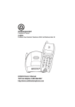
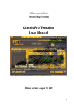
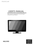
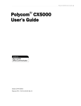
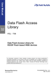
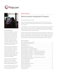
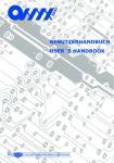
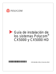
® Polycom CX5000 System Deployment Guide 3725-64352-001/ Rev D| January 2012 Polycom CX5000 Deployment Guide Trademark Information POLYCOM®, the Polycom "Triangles" logo and the names and marks associated with Polycom's products are trademarks and/or service marks of Polycom, Inc. and are registered and/or common law marks in the United States and various other countries. All other trademarks are property of their respective owners. No portion hereof may be reproduced or transmitted in any form or by any means, for any purpose other than the recipient's personal use, without the express written permission of Polycom. Patent Information The accompanying product may be protected by one or more U.S. and foreign patents and/or pending patent applications held by Polycom, Inc. Copyright Information © 2012 Polycom, Inc. All rights reserved. Polycom, Inc. 4750 Willow Road Pleasanton, CA 94588-2708 USA No part of this document may be reproduced or transmitted in any form or by any means, electronic or mechanical, for any purpose, without the express written permission of Polycom, Inc. Under the law, reproducing includes translating into another language or format. As between the parties, Polycom, Inc., retains title to and ownership of all proprietary rights with respect to the software contained within its products. The software is protected by United States copyright laws and international treaty provision. Therefore, you must treat the software like any other copyrighted material (e.g., a book or sound recording). Every effort has been made to ensure that the information in this manual is accurate. Polycom, Inc., is not responsible for printing or clerical errors. Information in this document is subject to change without notice. Information in this document, including URLs and other Internet Web site references, is subject to change without notice. Complying with all applicable copyright laws is the responsibility of the user. Without limiting the rights under copyright, no part of this document may be reproduced, stored in or introduced into a retrieval system, or transmitted in any form or by any means (electronic, mechanical, photocopying, recording, or otherwise), or for any purpose, without the express written permission of Microsoft Corporation and Polycom. Microsoft may have patents, patent applications, trademarks, copyrights, or other intellectual property rights covering subject matter in this document. Except as expressly provided in any written license agreement from Microsoft, the furnishing of this document does not give you any license to these patents, trademarks, copyrights, or other intellectual property. © 2010 Microsoft Corporation. All rights reserved. ii Polycom, Inc. Polycom CX5000 Deployment Guide Contents Introduction ................................................................................................................. 1 Polycom CX5000 Graphical User Interface ............................................................... 2 Touch Screen ........................................................................................................ 2 Informational Screen ............................................................................................ 3 Diagnostics Screen ............................................................................................... 4 Device Configuration ................................................................................................... 5 System Requirements for the Polycom CX5000 Device Computer ................... 5 Installing the Polycom CX5000 Device Management Tool ................................ 5 Connecting the Polycom CX5000 Device to the Computer ................................ 6 Using CX5000Manage.exe ................................................................................... 6 Configuring the Polycom CX5000 Device ............................................................ 8 Common Configuration Tasks ............................................................................ 17 Device Management Best Practices ........................................................................ 19 Security Best Practices ............................................................................................. 19 Deployment Best Practices....................................................................................... 19 Deployment Scenarios ....................................................................................... 20 Troubleshooting Techniques .................................................................................... 23 User Troubleshooting Guide ............................................................................... 23 Frequently Asked Questions............................................................................... 25 Interpreting the Diagnostics Logs ...................................................................... 26 Known Tools Issues ............................................................................................ 34 Regulatory Information ....................................................................................... 34 Support ................................................................................................................ 34 Safety Notices ..................................................................................................... 34 Polycom, Inc iii Polycom CX5000 Deployment Guide Introduction When you want to meet with people who are geographically separated, video conferencing gives you a greater sense of immediacy than a conventional telephone conference call. The Polycom CX5000 is a next generation video conferencing system that provides a comprehensive conferencing experience through the use of 360 degree video and active speaker detection. Figure 1. Polycom, Inc A Polycom CX5000 conference in session 1 Polycom CX5000 Deployment Guide Polycom CX5000 Graphical User Interface This section describes the top-level screens of the Polycom CX5000 graphical user interface (GUI). Touch Screen The Touch screen (Figure 2) is the screen that is displayed when the Polycom CX5000 device starts up. This screen contains status indicators (in the upper-right corner), a backspace key to erase previously-entered digits in on-hook dialing (just below the status indicators), and the keypad. From left to right, the status indicators show whether an external dial pad is connected, whether the Polycom CX5000 device is connected to a computer via USB, whether a phone line is connected to the Polycom CX5000 device, and whether there is an Ethernet connection to the Polycom CX5000 device. Figure 2. 2 Touch Screen Polycom, Inc. Polycom CX5000 Deployment Guide Informational Screen The Informational screen (Figure 3) is displayed when you press the Information button that is to the right of the display panel. Besides the status indicators described in the previous section, the Informational screen contains icons for four additional screens: Tutorial, Diagnostics, Info, and Speed Dial (viewing the icons left to right, and top to bottom). . Tutorial icon - opens the Tutorial screen, which contains a list of four tutorials on various aspects of using the Polycom CX5000 device. The tutorial subjects are: Quick Start, Call Handling, External Dial Pad, and Satellite Microphones. Info icon - opens the Info screen, which displays the device serial number, and firmware and software versions. Speed Dial icon - opens the Speed Dial screen, which lists the phone numbers that can be speeddialed. This list is empty until speed dialing numbers are configured for the device. For more information, see Pre-Programmed Speed Dials. Diagnostics icon - opens the Diagnostics screen (discussed in the next section), which provides information about the health of the Polycom CX5000 device. Figure 3. Polycom, Inc Informational Screen 3 Polycom CX5000 Deployment Guide Diagnostics Screen The Diagnostics screen (Figure 4) displays four icons that represent the main subsystems of a Polycom CX5000 device. (This screen also displays the previously discussed status indicators.) From left to right and top to bottom, the icons represent audio subsystem diagnostics, video subsystem diagnostics, systems diagnostics, and network subsystem diagnostics. Audio subsystem - includes audio health (Pass or Fail), whether satellite microphones are connected, the currently most active microphone, and active media. Video subsystem - includes the camera ID, camera health (Pass or Fail), white balancing settings, lighting frequency, and active media. System - includes the URL of the update server, the current time, the time of the last update, the time zone, and system health (Pass or Fail). Network subsystem - includes the IP address for the Polycom CX5000 device, subnet mask, the IP address of the default gateway, and the IP address of the DNS server. If you encounter problems with a Polycom CX5000 device, the hardware diagnostics screens (audio, video, and system) should be the first place you check. Figure 4. 4 Diagnostics Screen Polycom, Inc. Polycom CX5000 Deployment Guide Device Configuration This section summarizes the device configuration functionality of Polycom CX5000. System Requirements for the Polycom CX5000 Device Computer Operating system: Windows® XP™ (SP2 or later, 32-bit only), Windows Vista™ (32-bit or 64-bit) or Windows 7 (32-bit or 64-bit) CPU Speed: 2.0 GHz or higher RAM: 2 GB or higher Video card RAM: 128 MB or higher Microsoft® Office InfoPath® 2003 or later (to edit the device configuration) USB 2.0 port Installing the Polycom CX5000 Device Management Tool Before you can configure the Polycom CX5000 device, you must install the Polycom CX5000 Device Management Tool CX5000.msi. You can obtain CX5000.msi from Polycom CX5000 support page . By default, CX5000.msi installs the End-User License Agreement (EULA) to the %ProgramFiles%\Polycom CX5000\ directory, and creates one directory—Device Management — under this directory. CX5000.msi copies the following files to the Polycom CX5000\Device Management\ directory: CX5000Manage.exe - The Polycom CX5000 device configuration tool. The current version of this tool is in English only. Usage of this tool is described below in Using CX5000Manage.exe. DeviceConfig.xsn - The Office InfoPath template for Polycom CX5000 configuration. DefaultConfig.xml - An example XML file for configuring the device. Polycom, Inc 5 Polycom CX5000 Deployment Guide Connecting the Polycom CX5000 Device to the Computer To configure and manage the Polycom CX5000 device using CX5000Manage.exe, plug the Polycom CX5000 device's USB cable into an available USB port on the computer (Figure 5). USB 2.0 is required. Figure 5. Plug Polycom CX5000 USB cable into a port CX5000Manage.exe supports only one Polycom CX5000 device plugged into the computer at a time. Using CX5000Manage.exe CX5000Manage.exe is typically used with a switch that specifies one of three modes: image mode diagnostic mode configuration mode Table 1, Table 2, and Table 3 describe the mode commands and show the syntax for each. Image mode commands are used to update the firmware images of the Polycom CX5000 device's operating system or boot loader, or to download a new configuration. Diagnostic mode commands are used to send diagnostic logs to the image update server. Configuration mode commands are used for a variety of purposes, including resetting the password, setting the device time, and uploading a device configuration to the image update server. All but two operations prompt the user for the Polycom CX5000 password. The operations that do not require a password are listed here: For clarity, Table 1, Table 2, and Table 3 show only the switches used with CX5000Manage.exe. A complete command must include CX5000Manage or CX5000Manage.exe with the applicable switch, as in the following example: 6 Polycom, Inc. Polycom CX5000 Deployment Guide Table 1. Image mode commands Switch Description -m:img -help Shows usage and flags of the image mode -m:img -i:nk -f:<file path to nk.bin> -s:<file path to nk.cat> Performs a USB image update of Nk.bin, the operating system of the Polycom CX5000 device. -m:img -i:EBOOT -f:<file path to CPUEBOOT.bin> s:<file path to CPUEBOOT.cat> Performs a USB image update of Cpueboot.bin, the boot loader of the Polycom CX5000 device. -m:img -i:config -f:<file path to rtconfig.xml> Downloads a new configuration file to the Polycom CX5000 device. The device must be rebooted before the new configuration takes effect. After performing any of the image mode commands you must reboot the Polycom CX5000 device. You can do this by using the CX5000Manage boot command as shown in the following command: Table 2. Diagnostic mode commands Switch Description -m:diag -help Shows usage and flags of the diagnostic mode. -m:diag -l:flush Flushes diagnostics to the image update server. The exact location will be referenced in future documentation for the Microsoft Office Communications Server 2007 or Microsoft Lync™ Server 2010 Update Service. You will not be prompted for a password for this operation. Table 3. Configuration mode commands Switch Description -m:cfg -help Shows usage and flags of the configuration mode -m:cfg -t:now Sets the time of the Polycom CX5000 device with the time on the computer. -m:cfg -r Reboots the device. -m:cfg -p Sets the password for the device. The factory default password is 78491. -m:cfg -q:cfgparseresult Queries the parser result after a new configuration is downloaded to the device. -m:cfg -f:rtconfig.xml Uploads the Polycom CX5000 device configuration file to a server share on the Office Communications Server 2007 or Microsoft Lync Server 2010 Update Service. The factory-set default password is 78491. Polycom, Inc 7 Polycom CX5000 Deployment Guide Configuring the Polycom CX5000 Device Before applying new settings to a Polycom CX5000 device, ensure you have a supported version of Microsoft Office InfoPath installed. To apply new settings to a Polycom CX5000 device 1. In the %ProgramFiles%\Polycom CX5000\DeviceManagement\ directory, double-click DeviceConfig.xsn to launch the InfoPath form. Figure 6 shows a portion of this form. Figure 6. 8 InfoPath Form 2. After you change the settings to suit your particular installation, save the configuration (as RTConfig.xml, for example) to the same directory as CX5000Manage.exe. The section following this procedure provides details of the InfoPath configuration form. 3. Open a command prompt, change the directory to the %ProgramFiles%\Polycom CX5000\DeviceManagement\ directory, and type the following command line: 4. Check for any XML parsing errors by running this command: 5. If there are no errors, proceed to the next step. Otherwise fix the errors and repeat from step 3. 6. Reboot the device by running this command line: Polycom, Inc. Polycom CX5000 Deployment Guide The following tables provide details about the configuration changes that you can make in the InfoPath configuration user interface: Table 4. Field Room Settings Description Factory default Room name A text description (at most 63 characters) for the conference room. (empty string) Room size The approximate comfortable seating capacity of the conference room. There are three options: 7 – 11 people (Medium) 1 – 6 people (Small) 7 – 11 people (Medium) 12 or more people (Large) Table size The approximate size of the table in the conference room. There are three options: 10' x 5' (3.05 m x 1.52 m) 5' (1.52 m) Round 10' x 5' (3.05 m x 1.52 m) 20' x 5' (6.10 m x 1.52 m) Lighting A description of the lighting brightness in the conference room. There are three options: Normal Normal Dark Light Notes 1:, Notes 2:, Notes 3: Custom fields (at most 63 characters each) that the administrator can use to tag the devices. (empty string) The values of Room size and Lighting are not currently used by the firmware. Polycom, Inc 9 Polycom CX5000 Deployment Guide Table 5. Field Network Settings Description Factory default Device name A friendly name (at most 63 characters) for the device. Used in the diagnostics log for tagging the device. This is not the host name for the device. (empty string) DHCP enabled Determines whether Dynamic Host Control Protocol (DHCP) is enabled. The options are checked (DHCP is enabled) and unchecked (DHCP is disabled). Checked A check in this field corresponds to a value of "true"for the DHCPEnabled attribute in DefaultConfig.xml. If unchecked, the DHCPEnabled attribute has a value of "false". IP Address When DHCP is disabled, enter the IP address in xxx.xxx.xxx format (empty string) Subnet mask When DHCP is disabled, enter the subnet mask in xxx.xxx.xxx format (empty string) Default gateway When DHCP is disabled, enter the IP address of the default gateway in xxx.xxx.xxx format (empty string) Preferred DNS server When DHCP is disabled, enter the IP address of the preferred DNS server in xxx.xxx.xxx format (empty string) Alternate DNS server When DHCP is disabled, enter the IP address of the alternate DNS server in xxx.xxx.xxx format (empty string) Table 6. Field Time Settings Description Factory default Time zone Time zone for the device Set to time zone of the country in which the device is sold. For devices sold in the U.S. and Canada, the default time zone is Eastern standard time. See Table 15 for country-specific settings. Automatically adjust clock for daylight saving Checked or unchecked Checked 10 Reserved Polycom, Inc. Polycom CX5000 Deployment Guide Table 7. LCD Display Settings Field Display language Description Brazilian Portuguese Factory default Default language is determined by the country in which the device is sold. See Table 15 for countryspecific settings. Dutch English French German Italian Japanese Korean Simplified Chinese Spanish Traditional Chinese Screen saver text Reserved Table 8. Field (empty string) Telephony Settings Description Factory default Phone number Phone number for the Polycom CX5000 device (empty string) Flash timing 10 ms through 990 ms, in 10 ms increments Default settings for the target country's recommended regulatory compliance agency See Table 15 for countryspecific settings Ignore dial tone when dialing On or Off Off Reserved Table 9. Field Pre-Programmed Speed Dials Description Factory default Name Short name (at most 63 characters) of the number in the speed dial (empty string) Number Telephone number (at most 63 characters) (empty string) By default, the form shows one speed dial entry. You can use the form to add and program four additional speed dials. Polycom, Inc 11 Polycom CX5000 Deployment Guide Table 10. Software Updates Settings Field Description Factory default Automatically update using the image update server Checked or unchecked. If checked, automatic image updates are enabled. Checked Exclude configuration file from automatic update Checked or unchecked. If checked, the configuration file is excluded from automatic update. Unchecked Update time Time of day at half hour intervals 3:30 AM local time Update interval Every day Every day Every Sunday Every Monday Every Tuesday Every Wednesday Every Thursday Every Friday Every Saturday Server Name of the update server Ucupdates Port Port for device-server communication 80 Uniform resource identifier path URI path on the server with which to communicate. (empty string) Table 11. Field Logging Settings Description Factory default Log to server Checked or unchecked. If checked, diagnostic log data is sent to the server. Checked Upload time Time of day at half hour intervals 3:00 AM local time Update interval Every hour Every hour Every day Every Sunday Every Monday Every Tuesday Every Wednesday Every Thursday Every Friday Every Saturday Maximum log size in memory 12 Configurable size of memory reserved for the log. 1024 KB Polycom, Inc. Polycom CX5000 Deployment Guide Field Description Factory default It is recommended that you leave this set to 1024 KB. Server Name of the update server Ucupdates Port Port for device-server communication 80 Uniform resource identifier path URI path on the server to communicate with. (empty string) Table 12. Power Management Settings Field Turn off LCD backlight Description Amount of time (in minutes) after which the device's LCD backlighting is turned off, when there is no activity. Factory default After five minutes After one minute After five minutes After 10 minutes After 20 minutes After 30 minutes After 45 minutes After 60 minutes After 120 minutes After 180 minutes After 240 minutes After 300 minutes Table 13. Field Active speaker detection algorithm Advanced Settings Description The device will use either audio only or both audio and video to detect the current speaker. The options are: Factory default Use audio and video Use audio only Use audio and video Active speaker switching frequency Reserved Default White balance setting Auto or Manual Auto Light temperature If white balance setting is Manual, then the light temperature will be used. N/A Incandescent – 2800 K Cool white fluorescent – 4100 K Polycom, Inc 13 Polycom CX5000 Deployment Guide Field Description Factory default Daylight/sunlight – 6500 K Lighting frequency The lighting frequency can be set to the following values: Auto 50 Hz 60 Hz The lighting frequency setting should match the AC power frequency of the deployment location to ensure good video quality. If it is set to Auto, the device will attempt to detect the frequency from the power source. Automatic detection results may vary due to variance in the circuit at the time of detection. Table 14. Field The default lighting frequency is determined by the country in which the product is sold. See Table 15 for country-specific settings. For deployment in Japan, check the AC power frequency at the location, and ensure that Lighting frequency is set accordingly. Debugging Settings Description Factory default Audio debug logging Enable verbose audio debug logging. On or Off. Off Video debug logging Toggle verbose video debug logging. Off On or Off. System debug logging Toggle verbose system debug logging. On or Off. Table 15. Country LCD Display Settings – Display Language (see Table 1) Off Default Settings for Individual Countries Time Settings – Time Zone (see Table 6) Telephony Settings – Flash Timing (see Table 8) Advanced Settings – Lighting Frequency (see Table 13) Argentina Spanish GMT-3 300 ms 50 Hz Australia English GMT +10 100 ms 50 Hz Austria German GMT +1 100 ms 50 Hz Belgium English GMT +1 100 ms 50 Hz Brazil Brazilian Portuguese GMT - 3 300 ms 60 Hz Bulgaria English GMT + 2 100 ms 50 Hz Canada English GMT - 5 700 ms 60 Hz China Simplified Chinese GMT+8 100 ms 50 Hz Costa Rica Spanish GMT-6 700 ms 60 Hz Cyprus English GMT** 100 ms 50 Hz 14 Polycom, Inc. Polycom CX5000 Deployment Guide Country LCD Display Settings – Display Language (see Table 1) Time Settings – Time Zone (see Table 6) Telephony Settings – Flash Timing (see Table 8) Advanced Settings – Lighting Frequency (see Table 13) Czech Republic English GMT + 1 100 ms 50 Hz Denmark English GMT +1 100 ms 50 Hz Estonia English GMT + 2 100 ms 50 Hz Finland English GMT +2 100 ms 50 Hz France French GMT +1 100 ms 50 Hz Germany German GMT +1 100 ms 50 Hz Greece English GMT + 2 100 ms 50 Hz Hong Kong English GMT + 8 550 ms 50 Hz Hungary English GMT + 1 100 ms 50 Hz Iceland English GMT + 1** 100 ms 50 Hz India English GMT +5.5 300 ms 50 Hz Ireland English GMT 0 100 ms 50 Hz Israel English GMT+2 100 ms 50 Hz Italy Italian GMT +1 100 ms 50 Hz Japan Japanese GMT + 9 700 ms Auto* Latvia English GMT + 2 100 ms 50 Hz Liechtenstein English GMT + 1 100 ms 50 Hz Lithuania English GMT + 2 100 ms 50 Hz Luxembourg English GMT + 1 100 ms 50 Hz Malaysia English GMT+8 550 ms 50 Hz Malta English GMT** 100 ms 50 Hz Mexico Spanish GMT - 6 100 ms 60 Hz Netherlands Dutch GMT + 1 100 ms 50 Hz New Zealand English GMT +12 100 ms 50 Hz Norway English GMT +1 100 ms 50 Hz Polycom, Inc 15 Polycom CX5000 Deployment Guide Country LCD Display Settings – Display Language (see Table 1) Time Settings – Time Zone (see Table 6) Telephony Settings – Flash Timing (see Table 8) Advanced Settings – Lighting Frequency (see Table 13) Poland English GMT + 1 100 ms 50 Hz Portugal Brazilian Portuguese GMT 0 100 ms 50 Hz Romania English GMT + 2 100 ms 50 Hz Russia English GMT+3 100 ms 50 Hz Slovakia English GMT + 1 100 ms 50 Hz Slovenia English GMT + 1 100 ms 50 Hz Singapore English GMT +8 550 ms 50 Hz South Africa English GMT + 2 100 ms 50 Hz South Korea Korean GMT + 9 700 ms 60 Hz Spain Spanish GMT +1 100 ms 50 Hz Sweden English GMT +1 100 ms 50 Hz Switzerland German GMT +1 100 ms 50 Hz Taiwan Traditional Chinese GMT +8 700 ms 60 Hz Thailand English GMT + 7 550 ms 50 Hz United Arab Emirates English GMT** 100 ms 50 Hz United Kingdom English GMT 0 100 ms 50 Hz United States English GMT - 5 700 ms 60 Hz * For deployment in Japan, check the AC power frequency at the location, and ensure the lighting frequency is set accordingly. ** Default settings may differ from actual country time zone and may be reconfigured as needed. Refer to “Configuring the Polycom CX500 Device” for guidance. 16 Polycom, Inc. Polycom CX5000 Deployment Guide Common Configuration Tasks This section provides information on a number of common tasks that can be performed. For each command, it is assumed that you have opened a command prompt window, and that the current directory is %ProgramFiles%\Polycom CX5000\Device Management\. Set the Time The following command uses the computer's time to reset the time on the Polycom CX5000 device: Change the Display Language 1. Double-click DeviceConfig.xsn to launch the InfoPath form. 2. In the LCD Display section of the InfoPath form, change the Display language setting to the appropriate value. 3. Save the file (as RTConfig.xml, for example) to the directory that contains CX5000Manage.exe. 4. Open a command prompt and run the following command: 5. Check for any XML parsing errors using the following command: 6. If there is no error, proceed to the next step. Otherwise, fix the errors and repeat from step 3. 7. Reboot the device using the following command: Change the Time Zone 1. Double-click DeviceConfig.xsn to launch the InfoPath form. 2. In the Time section of the InfoPath form, change the Time zone setting to the appropriate time zone. 3. Save the file (as RTConfig.xml, for example) to the directory that contains CX5000Manage.exe. 4. In a command prompt, run the following command: 5. Check for any XML parsing errors using the following command: 6. If there are no errors, proceed to the next step. Otherwise, fix the errors and repeat from step 3. 7. Reboot the device using the following command: Get the Device's Current Configuration 1. Open a command prompt and run the following command: 2. The device configuration file will be uploaded to a server share on the Office Communications Server 2007 or Microsoft Lync Server 2010 Update Service. Polycom, Inc 17 Polycom CX5000 Deployment Guide Update the Firmware Images The fastest way to update the Polycom CX5000 device is by means of an automatic image update using the image update server. However, if you must update the device in the absence of the update server, you can use the USB image update functionality. 1. Obtain the latest firmware image files from the Polycom CX5000 support page. Boot loader package—CPUEBOOT.cat and CPUEBOOT.bin Operating system package—nk.cat and nk.bin 2. To update the boot loader, run the following command at a command prompt: 3. To update nk.bin, run the following command at a command prompt: Reset the Device to Factory Settings A Polycom CX5000 device stores two copies of its firmware: a read-only copy installed at the factory, and an updateable working copy. A Polycom CX5000 device ordinarily runs the updateable copy. When a device reset is performed, the working copy is erased. The device then boots the readonly factory firmware. The purpose of the factory firmware copy is to allow the user to update the Polycom CX5000 device with current firmware revisions without having to return the device to the factory. If you forget your device password or the firmware images have become corrupted (due to a power outage, for example), you can perform a factory reset. To perform a factory reset 1. Press and hold down the On/Off Hook button 2. While still holding down the On/Off Hook button , press and then release the Reset button at the back of the device. You will see a screen that prompts you (Figure 7) to confirm that you want to continue with the reset or to continue without resetting. Figure 7. 18 . Reset Screen 3. Press the Flash/Conference button to proceed with the reset, or press the Mute button to continue without resetting. Hold the Flash/Conference button until the device LED lights start to blink. If you do not hold this button long enough, the factory reset will not occur and the device will reboot. 4. After you perform a factory reset, apply the latest Polycom CX5000 firmware to the device to ensure the most secure operation and best performance. After a factory reset, you will Polycom, Inc. Polycom CX5000 Deployment Guide need to reapply the device configuration for your device. Failure to apply the latest Polycom CX5000 firmware after a factory reset can result in the device becoming noncompliant with telephony regulations in your country or region. Any liability resulting from failure to apply the latest firmware upgrade is the responsibility of the end user. Reset the Device Password 1. As a security best practice, change the device password from its default setting by running the following command line: 2. You will be prompted to enter the existing password, enter the new password, and then reenter the new password. The password consists of ANSI characters, and must be at least one character, but no more than 15 characters. Upload the Diagnostics Logs The following command line flushes diagnostic logs on the Polycom CX5000 device and sends them to the image update server: Device Management Best Practices Do not copy and paste CX5000Manage.exe commands that come in e-mail or from documents. Text from these kinds of documents often contains special characters that can be misinterpreted by CX5000Manage.exe. Typing the command directly into a command prompt is always preferred. Security Best Practices If you plan to use the Polycom CX5000 Ethernet port for remote configuration of the device, diagnostics logging, or automatic image update, ensure the device is configured properly. If you are not planning to use the Polycom CX5000 Ethernet port for such purposes, do not plug in the Ethernet cable. Deployment Best Practices This section contains information about characteristics of the conference room in which the Polycom CX5000 device is deployed. For best results, ensure your conference room adheres to these characteristics. Acoustical Characteristics Reverberation time (RT30): not longer than 300 milliseconds Background noise: less than 50 dBA SPL (sound pressure level) of background noise For tables larger than 15feet x 10feet, use satellite microphones Lighting Characteristics No direct sunlight or overhead light shining into the Polycom CX5000 lenses Lighting: fluorescent lighting with diffuser or ambient Lighting at 4100K (white color light) Wall color: white or other light color Lighting level: at least 300 lux Polycom, Inc 19 Polycom CX5000 Deployment Guide Miscellaneous Requirements Maximum room size: 25 feet x 15 feet x 10 feet Wired Ethernet to the computer running Microsoft Office Live Meeting, Office Communicator 2007 or Microsoft Lync 2010 client for video conferencing No loud projectors or other machines immediately adjacent to the device No loud noises (including typing) next to the device No clutter around the device to block the microphones Do not drag the device by the system cable Do not pick up the device by the camera head Analog phone line Follow the manual for optimal setup Power supply for the computer running Office Live Meeting, Office Communicator 2007 or Microsoft Lync 2010 client Deployment Scenarios This section shows four possible conference room configurations, two using circular tables, and two using rectangular tables. Note that the drawings are not to scale. Figure 8 shows a configuration in a small room with the Polycom CX5000 device (1) and one display device (2). The circular table is 5 feet in diameter. 1 2 Figure 8. 20 Circular table with one display device Polycom, Inc. Polycom CX5000 Deployment Guide Figure 9 shows a configuration with the Polycom CX5000 device (1) and three display devices (2). The circular table is 5 feet in diameter. 2 1 2 2 Figure 9. Circular table with multiple display devices Figure 10 shows a configuration with a rectangular table in a conference room capable of holding 12 to 16 people, and one display device (3). The table shown is approximately 5 feet x 10 feet. In this configuration, two satellite microphones (2) are shown connected to the Polycom CX5000 device (1). 1 2 Figure 10. Polycom, Inc 2 3 Rectangular table with one display device 21 Polycom CX5000 Deployment Guide Figure 11 shows a configuration with a rectangular table in a conference room capable of holding 12 to 16 people, and three display devices (3). The table shown is approximately 5 feet x 10 feet. In this configuration, two satellite microphones (2) are shown connected to the Polycom CX5000 device (1). 3 1 2 2 3 3 Figure 11. 22 Rectangular table with multiple devices Polycom, Inc. Polycom CX5000 Deployment Guide Troubleshooting Techniques This section provides several techniques for solving commonly-occurring problems, and also contains a list of frequently asked questions (FAQ). If you run into problems using a Polycom CX5000 device, the techniques listed here might be of use to you. User Troubleshooting Guide Video on monitor and projector are different Symptom The video on a projector differs from what appears on the computer monitor, switching between the Active Speaker Video and Panoramic Video views. This is a bug in DirectShow. The procedure below might be able to help you resolve this problem. Resolution 1. Click Start then Control Panel. 2. In Control Panel, double-click Display. 3. On the Display Properties page, click the Settings tab, then Advanced. 4. On the monitor's property page, click the Troubleshoot tab. 5. Decrease hardware acceleration one step at a time and see if the problem disappears. Figure 12. Hardware Acceleration Video does not start Symptom In an Office Live Meeting, Office Communicator 2007, or Microsoft Lync 2010 session, the Active Speaker Video or Panoramic Video does not start. Resolution Polycom, Inc Ensure the video is started. 23 Polycom CX5000 Deployment Guide If this does not resolve the problem, check the computer to see if there are any other applications that have opened the problematic video stream. For example, in Windows XP, if you have the video preview on for Active Speaker Video, you cannot use the same web cam for your Office Live Meeting, Office Communicator 2007, or Microsoft Lync 2010 video session. No audio Symptom There is no audio in a VoIP call via computer in Office Live Meeting, Office Communicator 2007 or Microsoft Lync 2010. Resolution Ensure the microphones are not muted. If you cannot hear a remote session participant: o Check that the remote participant's microphone is not muted. o Check that your speaker is not muted. o Check that your speaker volume is not at the lowest level. Dropped connections Symptom Network problems are causing dropped connections. Resolution Reconnect by using the Office Live Meeting. Office Communicator 2007 or Microsoft Lync 2010 user interface. If the issue persists, contact your administrator regarding network connectivity. No dial tone Symptom Public switched telephone network (PSTN) dial tone cannot be heard. Resolution Ensure the Polycom CX5000 device has power. Ensure the RJ11 jack is connected to an active telephone line (a PSTN analog line). If your PBX uses cadence dial tone, dial the number you want. Press the On/Off Hook button to get a dial tone. The LCD lights around the speaker should turn green when a dial tone is detected. Dial pad screen does not appear Symptom The Polycom CX5000 device has power, but never gets to the dial pad screen. Resolution 24 Reboot the device by unplugging the Power Data Box from the electrical receptacle, and then plugging it back in. If the device freezes in the boot-up progress screen, wait for 10 minutes to see if the problem goes away. If the problem persists after multiple attempts, contact Polycom Customer Support. Polycom, Inc. Polycom CX5000 Deployment Guide Device plays beeping sound and red LCD lights flash at startup Symptom The Polycom CX5000 device starts up, but plays a beeping sound and shows red LCD lights for a few seconds after the device boots up. Resolution Press the Info button, press the Diagnostics icon, and then press the Video diagnostics icon. Check the camera health on the video diagnostics screen. If the status is Fail and the device beeps with flashing red lights, the hardware is damaged. Contact Polycom Customer Support. LCD screen is blank Symptom The LCD screen on the Polycom CX5000 device is blank. Resolution Check that the device has power. General tips Do not cover the microphones and speakers. Speak towards the device. Sit at least 0.5 meter away from the camera head. Frequently Asked Questions Why do pictures look blurry in Office Live Meeting? Is the camera out of focus? Blurriness in Office Live Meeting video can result from a combination of the codec used by Office Live Meeting and network-introduced packet drops during periods of heavy network traffic. The Polycom CX5000 device is designed to work with typical conference rooms and does not require additional configuration to get the cameras in focus. To determine whether there are problems with the camera hardware on Windows XP, 32-bit edition: 1. Capture the blurry image in Office Live Meeting. 2. In My Computer, double-click Polycom CX5000 Active Speaker Video. 3. Compare the images against the blurry image you captured in Office Live Meeting. For best results, the conference room you are in should have sufficient lighting. 4. If the raw video from Polycom CX5000 is clear while the Office Live Meeting video is blurry, busy network conditions are causing packets to be dropped. To determine whether there are problems with the camera hardware on Windows Vista: 1. Capture the blurry image in Office Live Meeting. 2. Obtain the Graph Edit tool (graphedt.exe ) from the latest DirectX SDK from Microsoft.com. 3. Launch graphedt.exe. 4. On the Graph menu, click Insert Filters. This opens a dialog box that you can use to insert filters for the video devices. Polycom, Inc 25 Polycom CX5000 Deployment Guide 5. Choose both Polycom CX5000 video devices under Video Capture Sources, press Insert Filters, and close the dialog box. 6. Ensure you click on the properties and ensure the I420 sources are used. 7. Click Play to render video. 8. Compare the images from GraphEdt.exe against the Office Live Meeting images. 9. If the raw video from Polycom CX5000 is clear while the Office Live Meeting video is blurry, busy network conditions are causing packets to be dropped. When I connect the Polycom CX5000 power data box to the network, why doesn't the device appear on the network? The device is not recognized on the network because it does not have an assigned IP address. After you connect the Polycom CX5000 power data box to the network, you must reboot the Polycom CX5000 device. To verify that Polycom CX5000 is on the network, press the Information button , then press the Device Diagnostics icon (in the upper right corner of this screen), and then press the Network Diagnostics icon (in the lower right corner of this screen). The IP Address field should contain a valid IP address. Interpreting the Diagnostics Logs This section describes several CE logging tasks, diagnostics logging, and Watson dump features of Polycom CX5000. CE Logging Tasks Polycom CX5000 writes to the CE Log for hardware functional tests and critical system issues. This section identifies a number of tasks related to the CE log that you can perform. Send the CE Log to the Update Service Server 1. Open a command prompt, and execute the following command line: 2. This command causes the Polycom CX5000 CE log to be uploaded to a server share on the Office Communications Server 2007 or the Microsoft Lync Server 2010 Update Service. See the Office Communications Server 2007 or the Lync Server 2010 documentation for the location of the file share. 3. The CE log for the device is written to a directory on the share. The directory name is the Product ID of the device. 4. The CE log file name has the form YYYYMMDDHHMMSS-CELOGn.clg, where n is 0 or 1. An example CE log filename is 20070501170926-CELOG0.clg. The file name might change based on the implementation of Office Communications Server 2007 or the Lync Server 2010 Update Service. Interpret the CE Log You must use Readlog.exe that ships with Microsoft Windows CE Platform Builder to interpret the .clg file. Alternatively, you can send the file to Polycom Customer Support for investigation. For information about Readlog.exe, see http://msdn2.microsoft.com/en-us/library/ms905162.aspx. 1. 26 To extract the contents of the .clg file to a text file, use the -v (verbose) print option when you run Readlog.exe. For example, . Polycom, Inc. Polycom CX5000 Deployment Guide 2. The CE log contains the results of the hardware functional tests as well as critical system errors. The following is an example of the contents of a CE log: A hardware failure can be identified by a FAIL in the following entries: Polycom, Inc 27 Polycom CX5000 Deployment Guide The CE logs are not localized because they are needed for debugging by developers. Errata in the Polycom CX5000 CE log The CE log contains a benign erroneous entry, similar to the following: The NORFLASH VERIFY test is not run and does not need to be run. In the event of a NOR Flash failure, the Polycom CX5000 device will not boot. Diagnostics Logging If the Log to the server field is checked in the Logging section of the Polycom CX5000 device configuration, the device writes self-diagnostic data to the Office Communications Server 2007 or the Lync Server 2010 Update Service. For the file name and location of the log, refer to the documentation for Office Communications Server 2007 or the Lync Server 2010 Update Service. Diagnostics Log Schema Table 16 lists the column names and their data types by column number. Data in the diagnostics log is comma-delimited. Table 16. Diagnostic Log Schema Names by Column Number Column Number Column Name and Data Type 1 DeviceType (varchar(32)) 2 Date Time (datetime) 3 ID (varchar(32)) (Product ID from Polycom CX5000) 4 LoggingType (Error/Health/Debug/POST) 5 Device Name (varchar(32)) 6 Component (varchar(32)) (Hardware | System | Video | Audio) 7 SubComponent1 (varchar(32)) 8 SubComponent2 (varchar(32)) 9 SubComponent3 (varchar(32)) 10 Property (varchar(32)) 11 Value1 (varchar(64)) 12 Value2 (varchar(64)) 13 Value3 (varchar(64)) 14 Value4 (varchar(64)) 15 Value5 (varchar(64)) 28 Polycom, Inc. Polycom CX5000 Deployment Guide Interpreting Diagnostics Logs The Polycom CX5000 diagnostics logs fall into three LoggingType categories: POST, Health, and Image Update. Power-on self test (POST) diagnostics consist of information generated when the device is powered on. Health diagnostics pertain to the health of the device, with regard to either system performance or resource usage. Image update diagnostics pertain to updating the device firmware. LoggingType == POST Polycom CX5000 powers on and performs a power on self test (POST). Table 17 shows the columns used, along with values that are logged. The three values of Component represent the system, audio digital signal processor, and video digital signal processor. Table 17. Columns and Values Used in POST Logging Physical Column Value Logged Device Type CX5000 Date Time Value of [Date Time] ID Value of [Product ID] LoggingType POST Device Name Value of [Device Name] Component System | ADSP | VDSP When Component = System, only the Property, Value2, and Value3 columns are used. The Property column contains the name of the test. The Value2 column contain the status (PASS | FAIL | NOT DONE | NA). The Value3 column contains the detailed status code. These entries indicate the general health of the system. Note that some entries are reserved for system use. Table 18 shows the possible values in the Property, Value2, and Value3 columns when the Component value is System. Table 18. Properties and Values for POST Logging, Component == System Property Value2 Value3 ADSP Microphone Test PASS | FAIL NULL CPU STATUS PASS | FAIL Status code Display Hardware PASS | FAIL Detailed status ETH0 TEST NOT DONE Reserved ETH1 TEST NOT DONE Reserved FIRMWARE CURRENT REV NA Reserved FIRMWARE FACTORY REV NA Revision number for factory default version of EBOOT.bin in the format of 1.0.xxxx.x FIRMWARE REV NA Polycom, Inc Revision number for working version of EBOOT.bin in 29 Polycom CX5000 Deployment Guide Property Value2 Value3 the format of 1.0.xxxx.x HCD1: Initialize PASS | FAIL Status code HCD3: Initialize PASS | FAIL Status code LCD VERIFY PASS | FAIL Status code NANDFLASH VERIFY PASS | FAIL Status code NORFLASH VERIFY NOT DONE Reserved OS REV NA Revision number for working version nk.bin in the format of 1.0.xxxx.x POST Version NA Reserved PSTN PASS | FAIL Initialization RTC VERIFY PASS | FAIL Status code SDRAM TEST PASS | FAIL Status code System Cable PASS | FAIL Status code TOUCHCTL VERIFY PASS | FAIL Status code UFN1: Initialize PASS | FAIL Status code USBF ENUM STATUS PASS | FAIL Status code USBH ENUM STATUS PASS | FAIL Status code VDSP ENUM STATUS PASS | FAIL Status code When component = VDSP, only the Property, Value2, and Value3 columns are used. The Property column contains the name of the test. The Value2 column contains the status (PASS | FAIL | NOT DONE | NA). The Value3 column contains the detailed status code. These entries indicate the general health of the video subsystem. Table 19 shows the possible values in the Property, Value2, and Value3 columns when the Component value is VDSP. Table 19. Property Properties and Values for POST Logging, Component == VDSP Value2 Value3 Calibration PASS | FAIL OK | FAIL Camera ID PASS | FAIL The camera ID Camera Video PASS | FAIL XXXXX 30 The health of each of the five cameras. X can be Y or N, Polycom, Inc. Polycom CX5000 Deployment Guide Property Value2 Value3 with Y = Pass and N = Fail I2C Status PASS | FAIL OK | FAIL POST PASS | FAIL OK | FAIL Restarts PASS | FAIL Number of restarts since boot Stack Health PASS | FAIL OK | FAIL Video Port PASS | FAIL X Frames Dropped. White Balance PASS | FAIL YES | NO (Expect yes) When Component = ADSP, only the Property, Value2, and Value3 columns are used. The Property] column contains the name of the test. The Value2 column contain the status (PASS | FAIL | NOT DONE | NA). The Value3 column contains the detailed status code. These entries indicate the general health of the initialization phase of the audio sub-system. Table 20 shows the possible values in the Property, Value2, and Value3 columns when the Component value is ADSP. Table 20. Property Property and Values for POST Logging, Component == ADSP Value2 ADSP FBAB POST PASS | FAIL Value3 Detailed status Logging Type == Health There are two types of health logging: system performance and usage. This section discusses system performance logging. Usage logging is discussed in the next section. System performance refers to memory usage, system uptime, and health of the audio digital signal processor. Table 21 shows the columns used and values logged in health logging. Table 21. Columns and Values Used in System Performance Logging Physical Column Value Logged DeviceType CX5000 Date Time Value of [Date Time] ID Value of [Product ID] LoggingType Health Device Name Value of [Device Name] For performance logging, only the Component, Subcomponent, Property, and Value1 columns are used. 0 shows the possible values of these columns for System (either memory usage or uptime) and for audio digital signal processor (ADSP) health. Polycom, Inc 31 Polycom CX5000 Deployment Guide Table 22. Component Possible Values for Component, Subcomponent, Property, and Value1 Columns Subcomponent Property Value1 System Name of exe that the property applies. MemoryUsage Usage in bytes System NULL Uptime Up time since boot. ADSP NULL ADSP HEALTH nI2CStatus:<#> : nSPIErrorCounts: <#> : nSPILastError: <#> : nI2SReadGlitchCount: <#> : nI2SWriteGlitchCount: <#> : This section discusses usage logging. Table 23 shows the columns and values used when LoggingType == Health and Property == Usage. Table 23. Columns Used in Usage Logging Physical Column Value Logged DeviceType CX5000 Date Time Value of [Date Time] ID Value of [Product ID] LoggingType Health Device Name Value of [Device Name] Table 24 shows the columns and values used in usage logging. This type of usage logging uses the Component, Property, Value1, Value2, Value3, Value4, and Value5 columns. The Value3 value is the session type, which can be one of PcAudio, PcVideo, or PstnCall. When VoIP is used with Polycom CX5000, a PcAudio usage entry is logged with the start time and end time. When video streams are used in Polycom CX5000, a PcVideo usage entry is logged with the start time and end time. When Polycom CX5000 is used as an analog phone, a PstnCall usage entry is logged with the start time, end time, originating phone number (configured in the Polycom CX5000 device configuration), and the first digit of the dialed phone number. Table 24. Component Property Values Used in Usage Logging When Component == System Value1 Value2 Value3 Value4 Value 5 First digit of dialed number System Usage Start time End time PcAudio Null System Usage Start time End time PcVideo Null System Usage Start time End time PstnCall Phone number of the originating Polycom CX5000 Logging Type == Image Update 32 Polycom, Inc. Polycom CX5000 Deployment Guide To create a report on usage, import the diagnostics log into a database and create a view of all records where Component = System and Property = Usage. Table 25 shows the columns used and values logged when LoggingType == Image Update. Table 25. Columns and Values Used in Image UpdateLogging Physical Column Value Logged DeviceType CX5000 Date Time Value of [Date Time] ID Value of [Product ID] LoggingType Image Update Component System SubComponent1 <NULL> SubComponent2 <NULL> SubComponent3 <NULL> Property Version Value1 Value of [EBOOT Version] Value2 Value of [Nk.bin Timestamp] Value3 Value of [Config Timestamp] Value4 Value of [Last Update Time] Value5 Value of [Image Update Success/Fail] Watson Dumps If the Log to the server field is checked in the Logging section of the Polycom CX5000 device configuration, the device automatically logs to the same server in case of a crash. The dump files are in kdmp format. IT Pros can submit these logs to CSS to file bug reports. The dump files can be read using Windows CE Dump Viewer. For more information, see http://www.microsoft.com/downloads/details.aspx?FamilyID=76B18828-09E4-4A87-A8E4A06F2352B754&displaylang=en. The Watson logs path on the server is under the \RTLogs\DiagLogs\ directory. The Watson log files encode the device serial number, the date, and the software revision number in the following naming convention: <Device Serial Number>-YYYY-MM-DDHHMMSS-WATSON-1.0.<Device Software Revision Number>.0.kdmp. An example Watson log file is 78491-322-0002937-00652-2007-0608151023-WATSON-1.0.3626.0.kdmp. Polycom, Inc 33 Polycom CX5000 Deployment Guide Known Tools Issues CX5000Manage.exe does not support more than one Polycom CX5000 device connected to a computer or laptop. CX5000Manage.exe does not exit if the USB cable is unplugged during a firmware image update. To exit CX5000Manage.exe in this situation, press CTRL+ C. The CE log cannot be read on the Office Communications Server 2007 or Microsoft Lync Server 2010 Update Service server. ReadLog.exe must be present on the server in order to read these logs. For more information, see Interpret the CE Log. Regulatory Information Regulatory information for the countries in which the Polycom CX5000 is approved for use can be found in the Polycom CX5000 Regulatory Manual, which is shipped with the Polycom CX5000 product and is also available online at http://support.polycom.com/PolycomService/support/us/support/voice/index.html Support Polycom® Customer Support (800) POLYCOM (765-9266) http://support.polycom.com/PolycomService/home/home.htm Online Documentation http://support.polycom.com/PolycomService/support/us/support/video/index.html Type CX5000 to search the Knowledge Base.Polycom CX5000System Release Notes Polycom CX5000 System Setup Guide Polycom CX5000 System Deployment Guide (this document) Quick Tips for Using the Polycom CX5000 System Polycom CX5000 System Users Guide Polycom CX5000 System Regulatory Information Safety Notices IMPORTANT SAFETY INSTRUCTIONS When using your telephone equipment, basic safety precautions should always be followed to reduce the risk of fire, electric shock and injury to persons, to include the following: Do not use this product near water, for example, near a bath tub, wash bowl, kitchen sink or laundry tub, in a wet basement or near a swimming pool. Avoid using a telephone (other than a cordless type) during an electrical storm. There may be a remote risk of electric shock from lightning. Do not use the telephone to report a gas leak in the vicinity of the leak. SAVE THESE INSTRUCTIONS 34 Polycom, Inc.