1
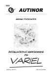
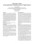
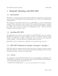
OptiView User’s Manual
Part I – Introduction
What is the OptiView System?
The OptiView System is a video viewing system. It allows slow-motion or freeze-frame viewing
in real time of objects that exhibit periodic motion. The OptiView is designed for applications
involving repetitive motion, such as vibrating, reciprocating or rotating objects with periods
between 10 and 1000 cycles per second.
A common application is monitoring frequency sweep tests of vibrating (shaker) test systems.
The system can also be used to determine the frequency of motion of an object.
How Does the OptiView System Work?
The OptiView System consists of a video camera and a controller that lets you adjust the periodic
opening and closing of the camera shutter. Adjusting the shutter opening to coincide with a
particular phase of the object’s motion results in a freeze-frame view. Adjusting the period of the
shutter opening to be slightly out of phase with the object’s motion produces a slow-motion view.
You can automatically synchronize the camera controller to a signal from the subject. You can
also choose to let the OptiView generate a small offset frequency to produce slow-motion
viewing for an object with constant or changing frequency.
The color video camera has a solid-state, high-speed shutter permitting precise, crisp capture of
the subject, similar to a snapshot. You can use the camera controller for remote set-up and for
adjustment of the camera parameters, including shutter speed. The controller produces standard
NTSC video output which can be sent to a monitor for viewing. The OptiView system gives you
the option of recording the video signal on standard VHS videotape.
The system is suitable for indoor and outdoor use. Although proper lighting is necessary for
viewing the object in either case, high ambient lighting in outdoor environments often is adequate
on its own. The external synchronized output can drive a strobe light to provide maximum light at
the times the shutter is open.
System Requirements
The minimum configuration for the OptiView System is:
! Camera
! Controller
! Cable for connecting camera to controller
OptiView User’s Manual
Version 3.1 Online
Page 1
IM1009 Apr 2004
! BNC-to-BNC cable for connecting controller to monitor
! Monitor
You may also add a VCR and/or the optional Fiberscope.
Part II -- Setting Up
Before You Begin
When you are setting up your OptiView, you should take some steps to ensure that you do not
damage your system. You must also make certain that you have arranged proper lighting to get
the best results.
Care of the Camera
The camera is very sensitive to mechanical abuse.
! Do not drop or bang the camera. This could damage the shutter or the camera electronics.
! Store the camera in its case to prevent shutter damage from extended exposure to UV light.
Connections
Making connections while the system power is on can damage the equipment.
! Turn the power off before you connect the camera and remote
Power off
control to the operator.
before
! Turn the power off before you connect an external trigger
connecting!
between the video signal and any other equipment.
! Remove power from the controller before you attempt to connect any wires.
Lighting
You can use the OptiView system with natural light alone, with artificial light alone or with the
two combined.
! Arrange the system so that any source of natural light is behind the camera.
! Place any artificial light source either behind the subject or between the subject and the
camera.
! Increase the amount of lighting you use as the operating frequency of the system increases.
! Avoid using AC-powered lights if the observation frequency of the system is close to the
AC line frequency. This could cause flashing of the video image due to frequency beats. If
your frequency is in a problem area, such as around 60HZ or 120Hz, use DC-powered light
instead.
Note If you are using the optional Fiberscope, see the additional discussion of lighting on page 7
of this manual.
OptiView User’s Manual
Version 3.1 Online
Page 2
IM1009 Apr 2004
Equipment Connections
This section describes how to connect the various pieces of
equipment you will be using with your OptiView System. All
connectors should fit together easily. Never force a connector
into its mating socket. Before you try to insert a connector,
verify that its key is in the right position.
Stop!
Power off.
Do not force connectors.
Please ensure that power is removed before you connect any equipment. Refer to Figure 2 when
you are making the connections described below.
Subject
Color Imaging
Camera
w/ 12:1 zoom
Color
Monitor
Remote
Control
Opti-View
Controller
Video In
Camera Control
Video OSD
Option
External Trigger Input
Processed
Video
Out
VCR
(Optional)
RS-232
G Force and Frequency Test Input
Figure 1
Block Diagram of the OptiView System
Controller Connections
First, position the OptiView controller in its correct location—the one in which you plan to use it
for monitoring your application. Then, connect each of these five factory-supplied cables to their
connectors on the back panel of the controller:
! Power cord
! Remote control cord
! Multi-conductor camera cable (larger camera connector)
! Coaxial camera cable (smaller camera cable)
! Monitor cable (coaxial)
Camera
On/Off Power Switch
90-260 VAC / 50-60 HZ
Fuse 500 MA
Remote
Monitor Camera
1
Out
2 3 4 5 6 TB-1
In
Video
Figure 2
Rear panel of the OptiView Controller
OptiView User’s Manual
Version 3.1 Online
Page 3
IM1009 Apr 2004
Camera Connections
After you have connected the camera cables to the controller, make the connections to the camera
described here. You must also consider the placement of the camera before you can use the
OptiView System. If you are using the Fiberscope option, follow the directions on page 5 for
connecting to the Fiberscope and camera.
Mechanical Camera Connections
It is a good idea to mount the camera onto a tripod before you make any
electrical camera connections. This helps to ensure the safety of the
equipment and provides good support for the camera while you are
working with it. You can use your own tripod, or you can purchase one
from Diversified Optronix.
Using the optional
Fiberscope?
Follow the directions on
page 5
If you are using the Diversified Optronix tripod, and you are not using the optional Fiberscope:
1 Remove the camera sled from the top of the tripod.
2 Attach the sled to the camera bottom. A ¼”-20 bolt is sitting free in the center of the sled.
Insert this into the ¼”-20 hole on the bottom of the camera.
3 Set the tripod near the location in which the camera will be used.
4 Re-attach the sled to the tripod.
Electrical Camera Connections
You must make two connections to the camera using the supplied single harness. Both
connections must be seated properly if the camera is to work correctly.
1 Locate the Multi-conductor cable, the larger, black connector.
2 Locate the key on the connector and insert the connector into the mating socket on the
back of the camera.
3 Tighten the locking nut by turning it clockwise until the nut is snug.
4 Locate the Coaxial Wire, which has a BNC connector.
5 Line up the tabs on the camera-mounted socket to the BNC connector.
6 Insert the connector with the tabs clearing the shroud, then apply inward pressure to
rotate the BNC clockwise.
7 Rotate it until you feel it snap into place—about 90 degrees.
Camera Location
The location of the camera is critical in determining the image quality for the system.
! Locate the camera near the object you are observing with the viewing angle chosen to give
the best view of your area of interest. Your required field of view and zoom will determine
the exact distance from camera to object. The camera provides a 12:1 zoom, controlled
from the remote operator. Note that zoom and focus ranges are interdependent. You might
have to adjust zoom, focus and camera position to meet your requirements.
! A solid footing for the camera will minimize the camera’s exposure to movement or
vibration. This is important because movements or vibrations can cause distortion.
! If you are using natural light, try to locate the camera between the subject and the light
source.
! You might find that you need artificial light to illuminate the subject properly.
OptiView User’s Manual
Version 3.1 Online
Page 4
IM1009 Apr 2004
Setting Up the Optional Fiberscope
The fiber is delicate!
The optional Fiberscope extends the capability of the
Take care in using the Fiberscope
OptiView System for subjects that are difficult to view.
to keep the bend radius as wide as
This includes subjects that are small, in low-light
is practical for your measurement.
environments or in closed, confined or otherwise not
easily visible areas. The Fiberscope attaches to the front
of the OptiView Camera and requires a local light source. It is 3”W x 15”D x 3.7”H and weighs
four pounds. A 24” long bendable fiber bundle carries light into the subject area and returns a
visual image of the subject to the camera through focusing optics.
p
y
g
Fiber Optic
Scope
DC Light
Source
Subject
Color Imaging
Camera
Optical
Mixer
Enclosed
Area
Remote
Control
Video In
Camera Control
External Trigger Input
OptiView
Controller
Video OSD
Option
Color
Monitor
Processed
Video
Out
VCR
(Optional)
RS-232
G Force and Frequency Test Input
Figure 3
Block diagram of OptiView System with optional Fiberscope
You must set up the Fiberscope between the camera and the subject. To do this, you will need
to make the appropriate connections, arrange the lighting, and adjust the focus.
If you are setting up your system for the first time, follow the directions under Setting Up
Initially with the Fiberscope.
If you are adding the Fiberscope to an existing system, follow the directions under Adding
the Fiberscope.
In either case, keep in mind that the camera is delicate. Dropping or banging it may damage the
shutter or camera electronics.
Setting Up Initially with the Fiberscope
If this is the initial setup of your OptiView System, you will need to make some mechanical
connections and some electrical connections to include the Fiberscope.
OptiView User’s Manual
Version 3.1 Online
Page 5
IM1009 Apr 2004
Mechanical Connections
1 Position the camera on the Fiberscope sled. To do this, place the camera at the end of
the sled and slide the camera until its lens touches the Fiberscope lens.
2 Match the threaded holes on the camera bottom to the slotted holes of the Fiberscope
sled.
3 Insert the socket cap screws into the holes and tighten them using the Allen Wrench
provided.
(Steps 4 through 6 apply only if you are using a tripod.)
4 Attach the tripod adapter to the Fiberscope sled using the center hole of the sled.
5 Set the tripod near the location in which the camera will be used.
6 Mount the unit to the tripod.
Electrical Connections
Follow the directions on page 4 under Electrical Camera Connections.
Opti-View
Camera
Fiberscope
Option
Fiberscope Sled
1/4-20 Screws
Figure 4
The optional Fiberscope is 3”W x 15”D x 3.7”H and weighs four pounds
Adding the Fiberscope
If you are adding the Fiberscope to an already installed OptiView System, you will have to
undo some of the mechanical camera connections before you begin.
Mechanical Connections
1 Switch off power to the OptiView controller.
2 Disconnect the multi-conductor cable from the camera by turning the locking nut
counterclockwise. The locking nut is the largest outermost ring on the connector.
3 Disconnect the BNC cable from the camera by rotating it counterclockwise.
4 Remove the two screws located on the underside of the sled, and carefully lift the
camera from the sled.
5 Remove the tripod adapter, if you are using one, from the camera sled by turning the
screw ring counterclockwise.
6 Position the camera on the Fiberscope sled. To do this, place the camera at the end of
the sled and slide the camera until its lens touches the Fiberscope lens.
OptiView User’s Manual
Version 3.1 Online
Page 6
IM1009 Apr 2004
7 Match the threaded holes on the camera bottom to the slotted holes of the Fiberscope
sled.
8 Insert the socket cap screws into the holes and tighten them using the Allen Wrench
provided.
9 If you are using a tripod, attach the tripod adapter to the Fiberscope sled using the
center hole of the sled. Set the tripod near the location in which the camera will be
used and mount the unit to the tripod.
Electrical Connections
Redo the electrical connections by following the directions on page 4 under Electrical
Camera Connections.
Fiberscope Lighting
An independent illuminator is necessary to operate the Fiberscope package. You can use your
own or the DC light source available from Diversified Optronix.
Subject
Focus Ring
Opti-View
Camera
Fiberscope
Option
Illuminator
Figure 5
The optional Fiberscope showing independent illuminator
Focusing
We recommend bench set-up before testing to verify that the system is working correctly and to
adjust coarse focusing.
1 Place a test subject approximately two to four inches
away from the end of the Fiberscope.
You can use a stationary
2 Set the Illuminator to maximum intensity and switch it on.
subject for focusing, a
business card, for
A round white spot will appear on the object.
example,
or another item
3 Turn on the OptiView controller, and switch the
containing clear text to
NORMAL/SET-UP switch on the back panel to Set Up.
focus on.
4 Set the SYNC switch to Int
5 Set the Rate Adj knob to 100Hz or higher.
6 Using the camera remote control, zoom all the way in and select Auto Focus. Adjust the
focus ring located between the camera and the Fiberscope until you have a generally clear
image.
7 Fine tune using the manual focus adjustment on the remote control.
OptiView User’s Manual
Version 3.1 Online
Page 7
IM1009 Apr 2004
The camera with the Fiberscope option is now ready for use. Additional focusing may be
necessary depending upon the subject working distance and other
factors. Most of the time, using the camera focusing control will
It is normal to see pixels
or dots on the screen.
provide adequate adjustment. In certain cases you may need to
These are the Fiberscope
manually adjust the focus ring again. If this becomes necessary,
fiber bundles.
we recommend switching the camera controller back to the Auto
Focus mode during manual adjustment of the Focus Ring.
Video Connections
The video monitor connection is a standard part of the OptiView System. You also have the
option of using a VCR to record the output of the controller.
Video Monitor
The video monitor displays the controller output. It connects to the controller via the BNC
connector marked Monitor on the back of the controller. The signal from the controller is
standard NTSC video output, compatible with most standard video equipment.
VCR
You have the option of using a standard VHS video recorder to record the signal from the
controller. If you plan to use a VCR, connect it between the controller and the monitor, using the
appropriate Video In and Video Out connectors of the VCR. If you are using a monitor that is
equipped with a Video Output signal, you can also connect the VCR after the monitor.
TB-1 Connections
If you plan to send external control signals to the controller, you will have to make one or more
connections to TB-1. Since you can plug and unplug the connector on TB-1, making connections
is easy. It has these six pins:
Pin
1
2
3
4
5
6
Description
+12V/500ma
output.
Available for
use to power
sensors
5V peak
shutter
frequency
pulse output.
To trigger a
strobe light or
output to other
equipment.
Synchronous
Input signal
for camera
shutter
control.
From 3V to
30V, sine or
square
wave, 10K
input
impedance.
Circuit
common.
Positive
isolated
external
synchronous
input. TTL
compatible,
0.5 to 10
ma, 2.5 to
20 V.
Negative
isolated
external
synchronous
input. TTL
compatible,
0.5 to 10
ma, 2.5 to
20 V.
Note Connect only isolated external synchronous signals to pins 3 and 4. If a signal is not
isolated, connect it to pins 5 and 6 instead.
OptiView User’s Manual
Version 3.1 Online
Page 8
IM1009 Apr 2004
1
2
3
4
5
6
TB-1
1
Common
Signal
Remote
Equipment
Output Trigger
Non Contact
Reflective
Sensor
2
3
4
5
6
TB-1
Signal
Common
+12 V DC
Figure 6
Two sets of typical connections that might be made to TB-1
RS-232 Interface Connections
The RS-232 port connection is used to receive and send data to the OptiView controller in this
configuration: 9600 baud, 8 bits, no parity and 1 stop bit. The controller can output information,
such as frequency, or it can receive information, such as accelerometer G-force. Received
information is in ASCII format and can be displayed on the monitor if you have installed the
optional On-screen Display. Contact the factory for further information on transmitting and
receiving information on this port.
Make these RS-232 connections:
Pin
1
6
7
8
9
OptiView User’s Manual
Connection
no connection
2
transmit output signal
3
receive output signal
4
not used
5
circuit common
Version 3.1 Online
Page 9
IM1009 Apr 2004
Part III – Using the OptiView System
Start-up
Using the OptiView system is straightforward. Point the camera at the subject and control the
camera with the remote. The controller unit controls the shutter. The video output is a standard
NTSC signal that is sent to a video monitor or VCR
OptiView 300
Rate Adj.
Set
INT.
HZ
EXT.
SYNC.
Open Time
RPM
DISPLAY
Figure 7
The front panel of the OptiView Controller
After you have made all the required connections (see Part II of this manual) and have located
the camera and controller correctly, you are ready to start the OptiView system. Turn the monitor
on first. Next, turn on the power to the controller using the rocker switch on its back panel. There
is a delay of about five seconds before an image appears on the monitor.
Front Panel
There are five controls on the front panel of the Controller:
Sync
Display
Rate Adj
Set
Open Time
Sync
The Sync switch lets you select how the operating frequency will bet set. Choose Int if you will
use an internally generated frequency via the Rate Adj knob described below. Choose Ext if you
will be using an externally generated frequency from either a sensor or another piece of
equipment. See TB-1 Connections, page 8.
OptiView User’s Manual
Version 3.1 Online
Page 10
IM1009 Apr 2004
Display
The Display switch lets you select the units for the display. Choose Hz for Hertz or rpm for
revolutions per minute. Since 1 Hz equals 1 cycle per second, a value displayed in rpm will be 60
times the same value in Hz.
Rate Adj
The Rate Adj knob works in one of two ways depending upon how you have set the Sync switch.
If you have set Sync to Int, the Rate Adj knob sets the operating frequency of the OptiView.
Turn the knob clockwise to increase the frequency in steps of about 0.1 Hz. Turn it counterclockwise to decrease the frequency. To adjust the frequency more quickly, press the knob in and
turn it while it is pressed. A half-rotation of the knob will produce medium frequency adjustment.
Going beyond half a rotation produces a coarse frequency adjustment. The current frequency
appears on the monitor as you adjust it.
If you have set Sync to Ext, the Rate Adj knob sets the amount of offset, if any, between the
OptiView frequency and the frequency of the incoming external synchronous signal. An offset
frequency produces a slow-motion view of the subject. The OptiView maintains this offset, even
if the external frequency changes. Turn the knob clockwise to produce a positive frequency
offset. Turn it counterclockwise for a negative offset. Pressing the knob has no effect on the speed
of the adjustment. See the Set button below to remove the offset.
Set
The Set button works in one of two ways, depending upon your setting of the Sync switch.
If you have set Sync to Int, the Set button changes the operating speed of the OptiView system.
Press it once to double the operating frequency. Press it again to halve the frequency. Press it a
third time to return to the original operating frequency.
If you have set Sync to Ext, the Set button returns to freeze-frame viewing of your object. If you
are operating in External Synchronization mode—that is, you have set the Sync button to Ext—
press the Set button to reset the existing offset to none. Selecting a frequency offset with the Rate
Adj knob creates a slow-motion view of your object and pressing the Set button locks the
OptiView frequency into perfect synchronization with the external synchronous signal, producing
a freeze-frame view.
Open Time
The Open Time adjustment sets the length of time that the shutter remains open. The factory
setting is chosen to be the best for the full range of the OptiView’s operation. You can adjust this
to maximize viewing specifically for your monitoring frequency. Make this adjustment only after
you have set the lighting, zoom, focus and brightness.
Adjust the Open Time by inserting a small flat-blade screwdriver into the hole labeled Open
Time. This allows you to reach the internal potentiometer. Turning the adjustment clockwise
increases the time the shutter remains open, which increases the brightness. Avoid turning it too
much or the subject will begin to go out of focus.1 Turning the adjustment counterclockwise
decreases the open shutter time. If you adjust too much in this direction, the image will not be
bright enough for effective viewing. The adjustment level appropriate for your application will
1
As you turn the adjustment too far, you will notice the subject becoming hazy and then out of focus.
OptiView User’s Manual
Version 3.1 Online
Page 11
IM1009 Apr 2004
depend upon several factors, including your operating frequency. You might have to adopt a trialand-error approach to find the right setting.
Rear Panel
The Set-up switch is located on the rear panel of the controller. It toggles between set-up mode
and normal operating mode.
In normal mode, the ratio of open shutter time to closed shutter time is small. The shutter is open
only long enough to capture the object’s motion at the appropriate moment. Set-up mode
reverses that situation; the shutter is now open at times it would normally be closed and closed at
times it would normally be open. Set-up mode serves two functions:
it facilitates camera set-up
it provides a “balancing” period for the shutter after the OptiView has been operating
Camera Set-up
It is difficult to view your subject when the shutter remains open for only a brief period. If you
switch to Set-up mode, the increased length of open-shutter periods makes it easier to locate the
camera and to test its zoom and focus. When you have finished setting up the camera, toggle the
switch back to Normal to operate the OptiView.
Balancing the Shutter
Warning!
The OptiView system uses an electronic shutter. It operates on a
Match all Normal mode
principal similar to that of an LED which means it requires roughly
time with Set-up mode
equal amounts of time in the open and the closed positions to
time, or your warranty will
maintain maximum shutter life. In the normal course of using the
be voided.
OptiView system, the shutter will be closed most of the time, so
you must compensate for this by running the system in the opposite
configuration. After any session using the OptiView, you should toggle the switch to Set-up and
leave the power on for a length of time approximately equal to the time it ran in Normal mode.
Failure to do this will void your warranty on the camera shutter.
Remote Control
All camera adjustments are made using the remote control attached to the controller. These
adjustments can be useful, particularly in difficult monitoring situations for which the automatic
settings may not be appropriate. The remote control allows you to set2
Focus
Zoom
Exposure Compensation
Auto Exposure
Date
Time
The camera memorizes its current settings when the OptiView system is turned off, and will
initialize with those settings when the power is returned.
2
Note that the Mode button of the camera remote control is not implemented in this version of the
OptiView system.
OptiView User’s Manual
Version 3.1 Online
Page 12
IM1009 Apr 2004
OptiView Camera Remote
-------Focus------In
Auto
Focus
Out
In
----Zoom----
Out
Exposure
Comp.
Up
Down
Bright
Shutter
Auto
Exposure
Down
UP
Mode
Date
Time
Figure 7
The OptiView camera remote
Focus
There are three buttons associated with camera focus: In, Out and Auto Focus. You can toggle
auto-focus between on and off by pressing the Auto Focus button which contains a small LED.
When Auto Focus is on, the LED is lit.
If you turn Auto Focus off, use the In and Out buttons to focus the
camera manually.
If you turn Auto Focus on, the camera will constantly perform
image focusing, even if the subject is still. To keep the unit in good
condition, it is best to avoid continuous use of the Auto Focus
feature.
Tip
For a fixed-focus
picture, use auto-focus
to obtain a focused
image, and then turn
auto-focus off when
you run the system.
Zoom
Two buttons control the camera zoom: In and Out. The maximum zoom is 12:1. Pressing the In
button increases the zoom. Pressing the Out button to decreases it. Keep in mind that the zoom
and the focus work together and are not independent of one another. It is possible to zoom in on
an object so closely that it becomes impossible to focus on it. In such cases, move the camera
closer to the object first; then adjust the zoom.
Exposure Compensation
Exposure compensation tries to produce the best possible image taking into account possible
areas of overly strong contrast. This can help prevent, for example, a single area of extreme
OptiView User’s Manual
Version 3.1 Online
Page 13
IM1009 Apr 2004
brightness from dominating. Press the Exposure Comp button to enable automatic exposure
compensation mode. Auto exposure must also be on. (see Auto Exposure below.) If you do not
use the automatic exposure compensation mode, use the ↑ and ↓ buttons to adjust the
compensation manually until you achieve a satisfactory image.
Exposure
Five buttons control exposure: Bright, Shutter, Auto Exposure, ↑ and ↓. The Bright, Shutter
and Auto Exposure buttons each represent a mode of operation and contain a small LED. Only
one of the three LEDs will be lit at any time, indicating which of the three modes is active.
Pressing any one of the three buttons activates the corresponding mode. In either Bright or
Shutter mode, the respective ↑ and ↓ buttons become active.
Auto Exposure
Auto exposure mode allows the camera to set the image brightness and shutter speed
automatically. The ↑ and ↓ buttons have no effect in this mode.
Bright
In Bright mode, you can adjust brightness manually using both gain and iris control. Use the ↑
and ↓ buttons to select from eight pre-set adjustment ranges.
Shutter
In Shutter mode, you can control the shutter speed manually. Use the ↑ and ↓ buttons to select
from eight pre-set adjustment shutter speeds. If you observe flickering on the monitor, you may
be able to adjust the shutter speed to eliminate or at least reduce the problem.
Date and Time
Two buttons control the display of the time and date on the monitor: Date and Time.
Date
Press the Date button once to activate display of the date. Press it again to deactivate the
display.
Time
Press the Time button once to activate display of the time. Press it again to deactivate the
display.
Setting the Date and Time
To set the date and time:
1 Press and hold down both the Date and the Time buttons together.
2 Hold for at least two seconds, releasing the buttons when the month and year appear on
the monitor.
3 The year will be flashing. Press the Date button until the correct year appears.
4 Press the Time button to set your year selection.
5 Repeat for the other Time and Date items.
When you have entered all the information, the OptiView will exit the Date and Time Set mode.
If you entered anything incorrectly, repeat the procedure.
OptiView User’s Manual
Version 3.1 Online
Page 14
IM1009 Apr 2004
Part IV – Technical Specifications
AC Power Input
The power cord supplied with the system connects AC power to the AC module which is located
in the rear of the controller. The AC module houses the Power On-Off switch and the fuses. Input
power must be from 90 to 260 VAC at 50 to 60 Hz.
Power On-Off Switch
The Power On-Off switch controls the main power to the controller and to the camera. Cycling
the power with this switch resets both the camera and the controller electronics.
Fuses
Replace fuses with type GMA, Bussman or equivalent, rated 500ma, 250VAC, 5 x 20 mm. To
replace a fuse
1 Unplug the 115VAC cord from the socket on the
back of the controller.
Caution!
2 Insert a small screwdriver into the slot to the left
Remove power from the
of the 15V socket.
controller before you
3 Pry out the fuse-holder assembly, causing the
check the fuses.
assembly and fuses to pop out.
4 Replace the fuses.
5 Line up the arrow on the fuse-holder assembly with the arrow on the controller and
reinstall the fuse-holder assembly.
6 Reapply power.
Power Cord
The OptiView System is shipped with a US standard 3-prong 115 VAC plug. You might have to
replace the plug at the end of the power cord if you are using higher voltages. To replace the plug
7 Remove the old connector at the end of the cord.
8 Connect the new plug so that the black and white wires carry the AC power.
9 Use the green wire for equipment ground (earth ground).
OptiView User’s Manual
Version 3.1 Online
Page 15
IM1009 Apr 2004