1
Liquid Crystal Variable Retarders
Liquid Crystal Variable Retarder response time depends on
several parameters, including layer thickness, viscosity,
temperature, variations in drive voltage and surface treatment.
Liquid crystal response time is proportional to the square
of the layer thickness and therefore, the square of the total
retardance.
a)
Response time improves by using custom materials with high
birefringence and a thinner liquid crystal layer. At higher
temperature, material viscosity decreases, also contributing to a
faster response. For speed critical applications, see page 56 for
Swift LC devices.
Our standard Liquid Crystal Variable Retarders provide a
minimum retardance range of ~30 nm to at least half-wave at
the specified wavelength. With an attached compensator,
retardance is guaranteed to range from zero to at least half-wave
at the specified wavelength. Custom retardance ranges (up to
a few waves) and custom compensators are available. Contact
our Sales Department to discuss your requirements.
b)
QUESTION
Liquid Crystal
Controllers
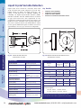
Each Liquid Crystal Variable Retarder is supplied with retardance
versus voltage performance data for your specified wavelength.
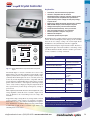
A coaxial cable with mating connector is provided for easy
attachment to one of our electronic controllers.
Liquid Crystal Devices
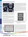
Another technique involves the Transient Nematic Effect (TNE)
to improve response times. With this drive method, a high
voltage spike is applied to accelerate the molecular alignment
parallel to the applied field. Voltage is then reduced to achieve
the desired retardance. When switching from low to high
retardance all voltage is momentarily removed to allow the
liquid crystal molecules to undergo natural relaxation. Response
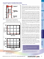
time achieved with the transient nematic effect is also shown
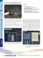
in figure 4-7c. Our Four Channel Digital Interface described on
pages 60-61 conveniently provides the necessary TNE voltage
profiles.
Mounting Hardware
Fig.4-7 Temporal response of LC Variable Retarder
The applied voltage is a 2 kHz square wave.
Excessive DC voltage will damage the liquid crystal
Retarders
Response time also depends upon direction of the retardance
change. If the retardance increases, response time is determined
solely by mechanical relaxation of the molecules. If retardance
decreases in value, response time is much faster due to the
increased electric field across the liquid crystal layer. Typical
response time for our standard visible Liquid Crystal Variable
Retarder is shown in figure 4-7b. It takes about 5 ms to switch
from one-half to zero waves (low to high voltage) and about 20
ms to switch from zero to one-half wave (high to low voltage).
Polarizers
Response Time
“The temporal response of a liquid-crystal device
seems very complicated. Where can I find some
clarification?”
ANSWER
Fig.4-8
Liquid Crystal Variable Retarder performance
versus applied voltage at 632.8 nm, 21° C.
(a) without compensator and
(b) with compensator
See our Application Note on temporal response of
liquid crystal devices at www.meadowlark.com.
[email protected] • (303) 833-4333 • www.meadowlark.com
49