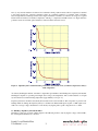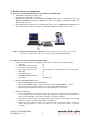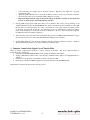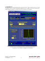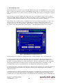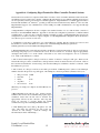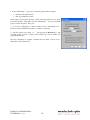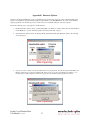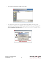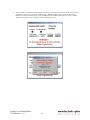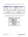
1
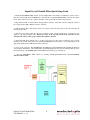
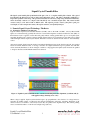
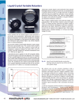
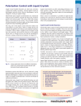
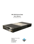
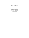
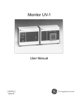
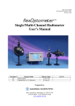
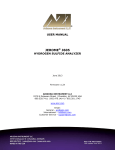
Liquid Crystal Tunable Filter User Manual Revision 2.00 Liquid Crystal Tunable Filter Quick Setup Guide 1. Install the FilterDRIVE 4000 software on a PC running Microsoft® Windows® (XP Service pack 3 or later). Place the included CD in the CD-ROM drive, and click the “Setup FilterDRIVE 4000” button in the autorun menu. If the menu does not run, open the “Installer” folder on the CD and double-click setup.exe. 2. Plug either the USB or serial cable into the appropriate connector on the filter controller. Plug the other end into an appropriate USB or RS232 connector on the PC. 3. With the tunable filter optics head positioned as desired, connect the optics head to the controller using the included 25-pin cable. 4. Plug the power supply cable into the power connector on the controller back panel. Connect the power supply to a properly grounded outlet. Ensure the vents on the top and bottom of the controller are not obstructed in order to ensure proper airflow through the controller. 5. Install the USB driver, making sure to get the correct version for the version of Windows (32 or 64 bit) installed on the system. This can be done via the FilterDRIVE CD autorun menu or by double-clicking on the appropriate installer in the USB Drivers folder on the CD. 6. Power on the controller. The POWER light will illuminate and the STATUS light will blink the firmware version during initialization. After initialization, the STATUS light will turn yellow, indicating that the optics head is heating up. The POWER light remains illuminated until the power is turned off. 7. Start the FilterDRIVE 4000 software by clicking Start/Programs/Meadowlark Optics/FilterDRIVE 4000/FilterDRIVE 4000.. Liquid Crystal Tunable Filter User Manual rev. 2.00 ii Liquid Crystal Tunable Filter Table of Contents Quick Setup Guide ..............................................................................................................................................ii Table of Contents ...............................................................................................................................................iii 1. Nematic Liquid Crystal Technology: The Basics ........................................................................................ 1 1.1 Nematic LCVR Physical Architecture ............................................................................................. 1 1.2 Building a Liquid Crystal Tunable Filter ......................................................................................... 2 2. Hardware Setup and Configuration ............................................................................................................. 3 2.1 Laboratory and System Requirements for the Liquid Crystal Tunable Filter .................................. 3 2.2 Setup Procedure for the Liquid Crystal Tunable Filter .................................................................... 3 3. Computer Control of the Liquid Crystal Tunable Filter............................................................................ 4 3.1 FilterDRIVE 4000 ........................................................................................................................... 5 3.1.1 Interface Control .............................................................................................................. 5 3.1.2 Wavelength Unit Selection .............................................................................................. 6 3.1.3 Wavelength Tuning Control ............................................................................................ 6 3.1.4 Temperature Status and Control ...................................................................................... 6 3.1.5 FWHM Status and Control .............................................................................................. 6 3.2 Temperature Status and Control Stages ........................................................................................... 7 3.3 FilterDRIVE Operation.................................................................................................................. 10 3.3.1 Front Panel Status LED Overview ................................................................................ 11 3.4 Additional Digital Interface Control Options ................................................................................. 12 3.4.1 HyperTerminal Command Line Control........................................................................ 12 3.4.2 USB Control via C/C++ Program .................................................................................. 13 3.4.3 Custom LabVIEW VI Control ....................................................................................... 13 4. Care and Maintenance of the Tunable Filter Optics ................................................................................ 13 5. Frequently Asked Questions ....................................................................................................................... 14 Appendix A: Configuring HyperTerminal for Filter Controller Terminal Sessions ................................. 15 Appendix B: Configuring HyperTerminal for Filter Controller Terminal Sessions ................................. 17 Appendix C: Software licensing ...................................................................................................................... 21 Software License Agreement ................................................................................................................ 21 Trademarks ........................................................................................................................................... 23 Liquid Crystal Tunable Filter User Manual rev. 2.00 iii Information in this document is subject to change without notice. Meadowlark Optics may have patents, patent applications, trademarks, copyrights, or other intellectual property rights covering subject matter in this document. Except as expressly provided in any written license agreement from Meadowlark Optics, the furnishing of this document does not give you any license to these patents, trademarks, copyrights, or other intellectual property. Please contact Meadowlark Optics for a list of applicable patents, trademarks, and/or copyrights. Copyright © 2005-2012 Meadowlark Optics, Incorporated. All rights reserved. Printed in the United States of America. Liquid Crystal Tunable Filter User Manual rev. 2.00 iv Liquid Crystal Tunable Filter The liquid crystal tunable filter from Meadowlark Optics, Inc. is a complete tunable filter solution. The optical head includes the filter itself as well as heater and temperature sensor. The filter is thermally stabilized by a temperature feedback control loop. The optical head mounts in a laboratory setup using standard 8-32 hardware, and it electrically connects to a compact control module by one convenient 25-pin cable. The control module connects easily to a PC with a USB or RS232 cable. The software provides control of the filter’s peak pass wavelength, as well as temperature status, through an attractive, user-friendly interface. 1. Nematic Liquid Crystal Technology: The Basics 1.1 Nematic LCVR Physical Architecture Typical nematic Liquid Crystal Variable Retarders (LCVRs) such as the LVR- and LRC- series by Meadowlark Optics are constructed using optically flat windows coated with transparent conductive indium tin oxide (ITO). A thin dielectric layer is applied over the ITO and gently rubbed, creating parallel micro-grooves for liquid crystal molecular alignment. Two windows are then carefully aligned and spaced several microns apart. The cavity is filled with birefringent nematic liquid crystal material. Electrical contacts are attached and the device is environmentally sealed. Anisotropic nematic liquid crystal molecules form uniaxial birefringent layers in the liquid crystal cell. An essential feature of nematic material is that, on average, molecules are aligned with their long axes parallel, but with their centers randomly distributed, as shown in Figure 1. With no voltage applied, the liquid crystal molecules lie parallel to the glass substrates and maximum retardation is achieved. Figure 1. Liquid Crystal Variable Retarder construction showing molecular alignment (a) without and (b) with applied voltage (drawing not to scale) When voltage is applied, liquid crystal molecules begin to tip perpendicular to the windows. As voltage increases, molecules tip further causing a reduction in the effective birefringence and hence, retardance. Molecules at the surface, however, are unable to rotate freely because they are pinned at the alignment layer. This surface pinning causes a residual retardance of ~30 nm even at high voltage (20 volts). Liquid Crystal Tunable Filter User Manual rev. 2.00 1 Zero (or any custom) retardance is achieved via a subtractive fixed polymer retarder, called a compensator, attached to the liquid crystal cell. Negative retardance values are sometimes preferred, for example, when converting between right and left circularly polarized states. Figure 2 illustrates retardance as a function of voltage for a typical LCVR with and without an attached compensator. Placing a compensated LCVR between two high extinction polarizers creates an excellent optical attenuator, with convenient electronic control. Figure 2. Liquid Crystal Variable Retarder performance at 632.8 nm, 21°C (a) without compensator, and (b) with compensator As with any birefringent material, retardance is dependent upon thickness and birefringence. Liquid crystal material birefringence depends on operating wavelength, drive voltage, and temperature. The overall retardance of a liquid crystal cell decreases with increasing temperature (approximately -0.4% per °C). Liquid crystal devices should be electrically driven with an AC waveform with no DC components to prevent ionic buildup which can damage the liquid crystal layer. LCVRs from Meadowlark Optics require a 2 kHz square wave with a zero-average voltage. Retardance is controlled by varying the peak-to-peak voltage from zero to ±10V. 1.2 Building a Liquid Crystal Tunable Filter The filter is composed of a stack of many dispersive LCVRs and polarizers. By varying the voltage on the LCVRs, the wavelengths transmitted are controlled. Liquid Crystal Tunable Filter User Manual rev. 2.00 2 2. Hardware Setup and Configuration 2.1 Laboratory and System Requirements for the Liquid Crystal Tunable Filter • 100-250 VAC, 50-60 Hz 1.5 A utility power. • A PC with an available USB or serial port. • Minimum PC requirements to run the included FilterDRIVE 4000 software are a Pentium® processor, 64 MB RAM, 200 MB hard drive space, 800x600 pixel, 16-bit color graphics, a CD-ROM, and Microsoft® Windows® XP, Vista or 7. • Recommended PC specifications are a 1-GHz Pentium® III processor, 256 MB RAM, 200 MB hard drive space, 1024x768 pixel, 16-bit color graphics, a CD-ROM, and Microsoft® Windows® XP, Vista or 7. Figure 3. Liquid crystal tunable filter components. (1) Tunable filter optics head (2) 25 pin optics head cable (3) Controller (4) USB or RS232 cable (5) Power supply (6) PC running FilterDRIVE 4000 2.2 Setup Procedure for the Liquid Crystal Tunable Filter 1. Unpack controller and cables from shipping container. Please verify that your shipment included: • Controller (1) • Tunable Filter optical head unit (1) • 25-conductor optical head cable (1) • Power supply and power cable (1 unit with DC power cable attached and 1 AC power cable) • USB cable (1) • Serial (RS232) cable (1) • FilterDRIVE 4000 software CD (1) • User manual (1 printed copy) 2. Install the FilterDRIVE 4000 software. • Place the FilterDRIVE CD in the CD-ROM drive. • Wait for the FilterDRIVE menu to appear, then click on the “Install FilterDRIVE …” button. • The software needs to be installed using a user account with administrator privileges. • Once the software installation is complete, the computer will need to be rebooted. 3. Hardware configuration: • Position the tunable filter optical head securely on an optics table or breadboard. The optical head has two 8-32 tapped holes for mounting the tunable filter optical head with standard optics hardware, as well as C-mount threading on both ends for mounting to specialized equipment. • The direction of light propagation through the filter is inconsequential. The markings on the housing indicate the direction of polarized light accepted or transmitted. • Connect the 25-pin optical head cable to the optical head. The optical head connector is shaped to disallow improper insertion. Connect the other end of the optical head connector to the filter controller. Liquid Crystal Tunable Filter User Manual rev. 2.00 3 • • • Connect the DC power supply cable to the filter controller. Plug the power supply into a properly grounded AC outlet. Attach the USB or RS232 cables to the USB or RS232 connectors on the rear of the filter controller, and connect the other end to an available USB or RS232 port on a PC. Important: Ensure that the vents on the bottom and top of the filter controller are not obstructed in order to ensure proper airflow through the controller. 4. If using USB, the appropriate USB driver must now be installed. This can be done by clicking on the “Install USB Driver” button in the FilteDRIVE CD’s menu. Alternately, the driver installer is in the USB Drivers directory on the CD. Please choose the correct driver for your system. There are separate version of the driver for 32 and 64 bit systems. For instructions on how to determine this, click on the “Help” button in the USB menu or see the text file in the “USB Drivers” directory. Once the installer completes, the USB driver has been installed completely. 5. Turn on the front panel switch and observe the LEDs. The green power LED remains illuminated as long as the controller is powered on. The status LED flashes the firmware version number. 6. If using USB, Windows® will detect new hardware after the controller completes its self-test. Windows should automatically pick the correct driver, which was installed in step 4. 3. Computer Control of the Liquid Crystal Tunable Filter There are several computer-based methods to control operation of the filter. The most common methods of interfacing to the controller are: 1. Using the standard FilterDRIVE 4000 software package from Meadowlark Optics. 2. Typing command-line ASCII control codes through a terminal interface (Microsoft® HyperTerminal, for example). 3. Using a C/C++ program that communicates with the controller via USB. 4. Developing a custom LabVIEW™ application using VIs included on the FilterDRIVE CD. Each method is described in detail in the following sections. Liquid Crystal Tunable Filter User Manual rev. 2.00 4 3.1 FilterDRIVE 4000 FilterDRIVE 4000 is a user-friendly filter interface program shown below. This program allows the user to change wavelengths as well as providing wavelength and temperature status. In addition to the controls described below, clicking the Meadowlark Optics logo displays the software and firmware version numbers. Figure 4: FilterDRIVE Software Display for selectable bandwidth filter, Sectioned By Function. (1) Interface Control, (2) Wavelength Unit Selection, (3) Wavelength Tuning Control, (4) Temperature Control and Status, (5) FWHM Control and Display. Liquid Crystal Tunable Filter User Manual rev. 2.00 5 3.1.1 Interface Control • • • Filter # Selects the current filter. Allows the user to switch between up to four filters attached to the same computer. If the filter is connected via the COM port, this display will be replaced with a display indicating the COM port to which the filter is connected. Interface Indicates the method used to interface with the filter and allows switching between USB and COM port control while the program is running. Port Test Allows the user to verify that the software is still in communication with the filter. The communications status will be displayed above the port test button. The status will also be indicated by the LED above Filter #. A green LED indicates a successful communication test. 3.1.2 Wavelength Unit Selection • Wavelength Units Indicates the current units selected for wavelength display/input. Allows the user to choose between units of nanometers (nm) or Angstroms (Å). All wavelength displays will be updated to 7reflect the new wavelength units chosen. 3.1.3 Wavelength Tuning Control • • • • Minimum Wavelength Indicates the minimum wavelength to which the filter is tunable. Current Wavelength Indicates the current wavelength and allows the user to type in a wavelength to which to tune the filter. The wavelength may also be increased or decreased by 0.1 nm (1 Å) at a time by using the up/down arrows on this control. Maximum Wavelength Indicates the maximum wavelength to which the filter is tunable. Wavelength Slider Allows the user to rapidly choose an approximate wavelength. The wavelength may also be increased or decreased by 1 nm (10 Å) at a time by using the arrows on either end of the slider. See section 3.4 below for more information on the use of these controls. 3.1.4 Temperature Status and Control • • • • Temperature Status Indicates the current temperature control status both with an LED and a message. See section 3.2 below for more details on the different temperature control status states of the filter. Temperature Indicates the current temperature of the filter. Temperature Update Flashes to indicate when the current temperature is read from the controller and written to the Temperature display. Temperature Stabilization (Not Shown) Appears when the temperature of the filter is stabilizing. See Figure 6 in section 3.2 below for more details. 3.1.5 Full Width at Half Maximum Control and Display (Selectable Bandwidth Filter only) • • • FWHM Size Allows the FWHM to be selected. Choices are narrow, medium and wide. FWHM displays the approximate size of the FWHM for the currently selected center wavelength. The filter is designed to have a smooth, monotonic increase in FWHM as a function of increasing center wavelength. FWHM Plot gives a visual representation of the transmission of the filter around the selected wavelength. Liquid Crystal Tunable Filter User Manual rev. 2.00 6 3.2 Temperature Status and Control Stages The LC Tunable Filter requires a carefully controlled internal optics head temperature for accuracy. Because of this, there are two stages the unit will proceed through prior to being ready for operation. The first state is heating. This will be indicated by the controller status LED appearing yellow or orange. If the FilterDRIVE 4000 software is running the screen will appear as in Figure 5 below, where the orange temperature status LED indicates that the unit is heating up. The status LED on the controller will also blink red every time the temperature readout is updated. The temperature display may go above the normal setpoint of 40°C during heating; this is normal and happens in order to speed up heating time. The filter will return to its normal setpoint of 40°C prior to temperature stabilization. Figure 5. FilterDRIVE 4000 Software during heating stage. Once the filter has reached its setpoint of 40°C it goes into the temperature stabilization stage, as indicated on the controller by the status light alternating between green and yellow. Again, the status LED will flash red whenever the controller receives a command, so occasional red flashes will be seen. When the filter is in temperature stabilization mode, the FilterDRIVE screen will be as shown below in Figure 6. The yellow Temperature Status LED in FilterDRIVE indicates that the filter optics head temperature is being stabilized. Also indicated is the number of minutes remaining until the temperature is completely stabilized. Liquid Crystal Tunable Filter User Manual rev. 2.00 7 Figure 6. FilterDRIVE Screen During Temperature Stabilization The filter can be used during temperature stabilization, however, accuracy may be reduced. If the software is exited and restarted, stabilization will not be interrupted. Also, once stabilized, the temperature will remain stabilized as long as the unit is powered on. If the unit is powered off for any reason, however, the temperature will have to restabilize. Once the filter has been at its setpoint for thirty minutes the status LED on the controller will turn green, flashing red when commands are received. Once the temperature status LED has turned green filter accuracy will be optimum. FilterDRIVE will appear like Figure 7 below once the filter is in normal operating mode. Figure 7. FilterDRIVE Screen During Normal Operation. Liquid Crystal Tunable Filter User Manual rev. 2.00 8 If, however, the filter optics head temperature varies by more than a degree from its setpoint, the Temperature Status LED in FilterDRIVE and the status LED on the controller will turn red. FilterDRIVE will appear as in Figure 8 below in this state. If this state is encountered often, please contact Meadowlark Optics for assistance at 303-833433 or e-mail [email protected], as this may indicate a problem with the controller. Figure 8. FilterDRIVE Screen During a Temperature Error. Regardless of the state of the temperature status LED the software will accept new wavelengths. However, if the status is not Normal then the accuracy of the filter cannot be guaranteed. Liquid Crystal Tunable Filter User Manual rev. 2.00 9 3.3 FilterDRIVE Operation Once the filter has been connected to power and USB or RS232 and powered on, FilterDRIVE can be started. If the filter is connected via USB and is powered on, FilterDRIVE will appear like one of the screens shown in section 3.2 above. If the software does not detect a controller connected via USB, the following screen will appear as in figure 9 below. If the controller is connected via RS232 only, simply click on the “Select COM Port” button. If the controller is connected via USB, check the USB connection, make sure the unit is powered on, and turn the unit off and back on. After the unit finishes flashing its firmware version on the status LED, click on the Retry USB button. If the software detects a USB connection or if RS232 is chosen, the screen will then appear like one of the screens shown in section 3.2. If the unit is powered on and all cables are connected, and the software still does not recognize the controller, try restarting the PC to which the filter is connected. If the filter still does not respond to the software, contact Meadowlark Optics at 303-833-4335 or e-mail [email protected] for assistance. Figure 9. FilterDRIVE Port Configuration Screen Once the filter has been stabilized at operating temperature as indicated in Figure 7 above, it is ready for use. To select a new wavelength, either move the slider to the desired wavelength or type the wavelength into the wavelength number box and press enter. The wavelength can be adjusted by 1 nm increments with the arrows on the slider, or by 0.1nm increments, up or down, with the arrows on the side of the number box. Only wavelengths valid for the particular filter in use will be allowed to be input, either with the slider or the number box. The wavelength displayed refers to the peak transmission wavelength of the current passband of the filter. To switch between units of nanometers and Angstroms (1 Angstrom = 0.1 nanometer), choose the units desired from the Wavelength Units pull-down menu. Once the menu is released, all wavelength displays will be updated to reflect the new units. Communication may be verified by clicking the Port Test button. If communications are functioning, the indicator above the Port Test button will display “Passed” and the LED above the Filter # will briefly turn bright green. If communications are not functioning, the indicator above the Port Test button will display “Failed” and the LED will Liquid Crystal Tunable Filter User Manual rev. 2.00 10 briefly turn red. During testing, particularly when the filter is connected via RS232, the display above Port Test will display “Testing…” and the LED will be yellow. This is normal, but will probably not be seen during a port test while connected via USB. Current temperature as well as temperature control status are shown in the bottom portion of the display. The temperature setpoint is fixed at 40° C and cannot be changed. The Temperature Status display and LED indicate the current temperature control status as described in section 3.2. 3.3.1 Front Panel Status LED Overview The following is a list of appearances the status LED will take on, depending on the D4020’s status. • Flashing green and red: Firmware version number is being flashed (occurs after power up or on receipt of a ver:? command). • Solid yellow: Filter housing temperature is not yet up to the reference temperature. Filter can still be used but accuracy may be degraded. • Blinking green and yellow: Filter housing temperature has reached the reference temperature, optics temperature is stabilizing. The software will show a countdown timer to indicate time to optimal temperature profile. Filter can still be used but accuracy may be degraded. • Solid green: Normal operation. • Solid red: Indicates problem with filter temperature. • Brief red flash: Indicates a command was received by the controller via RS-232 or USB. 3.4 Additional Digital Interface Control Options The user has several other digital interface control options; via a HyperTerminal session, a user created program to communicate with the controller via USB, or by using custom LabVIEW VI’s supplied by Meadowlark Optics. Table 1 details a complete list of ASCII firmware commands that may be used when performing USB or HyperTerminal control. Note that all commands are lower case. 3.4.1 HyperTerminal Command Line Control The HyperTerminal interface is available only through a COM port (RS-232) connection. After initiating a HyperTerminal session (see Appendix A for details), text commands are issued directly to the controller and responses are printed to the HyperTerminal screen. 3.4.2 USB Control via C/C++ Program The user may write a program that communicates directly with the controller through a USB connection. Included on the FilterDRIVE CD (Source Code folder) is a source code file (usb_ver.cpp) that initializes a USB connection to the controller, sends a ver:? command and reads the status response (after sending any command, status must be read before another command can be sent). This program may be used as a starting point and modified as necessary to perform the desired task(s). Header file usbdrvd.h must be included in the source code and the library file usbdrvd.dll (both included on the FilterDRIVE CD) must be linked in the final program. If a user developed or modified application program is to be distributed in any way, please contact Meadowlark Optics for licensing and copyright details. Table 1 ASCII commands for the Filter Controller Command Format Description Controller Response tmp:?<CR>1 returns the filter temperature tmp:xx.yy where xx.yy is the filter temperature to hundredths of degrees C ver: <CR>1 returns firmware version number and copyright message ver:5.00 ©…… ver:? <CR>1 1 flashes the firmware version number on the front panel status LED, then returns firmware version number and copyright message ver:5.00 ©…… All numeric parameters are in ASCII rather than binary, i.e. 6234 would be ASCII ‘6’,’2’,’3’,’4’. Liquid Crystal Tunable Filter User Manual rev. 2.00 11 wvl:xxx.x<CR>1 For the selectable bandwidth filter, the wavelength is in nanometers. Make sure the decimal point is included. wvl:? <CR>1 returns the current filter wavelength. tbl:n<CR>1 sets the current table for FWHM width. 1 selects wide, 2 medium and 3 narrow. returns the current table. 1 indicates wide FWHM, 2 indicates medium, and 3 indicates narrow. returns the min and max valid wavelengths, in angstroms. The return will be in the form xxx.x, yyy.y. The wavelength range will then be xxx.x,yyy.y. tbl:?<CR>1 mmwvl:? <CR>1 rsn:? <CR>1 returns the controller serial number Liquid Crystal Tunable Filter User Manual rev. 2.00 12 wvl: if wavelength was valid, wvl:invalid wavelength! if wavelength was invalid wvl:xxx.x where xxx.x is the current wavelength in nanometers. tbl: if table valid, tbl:invalid table if table number invalid. tbl:n, where n is the current table number. mmwvl:xxx.x,yyy.y where xxx.x is the minimum valid wavelength and yyy.y is the maximum valid wavelength, both in nanometers. rsn:xxxx, where xxxx is the serial number assigned to the controller 3.4.3 Custom LabVIEW VI Control Several VIs are included in a library file on the FilterDRIVE CD. This library can be found in the LabVIEW folder. LabVIEW VIs that interface with the controller via the serial port are: • Meadowlark LCTF Serial IO Example.VI • Meadowlark Serial LCTF Example.llb o Meadowlark Serial Com.VI o Meadowlark Serial Set Wavelength.VI o Meadowlark Serial Read Wavelength.VI o Meadowlark Serial Read Temperature.VI LabVIEW VIs that interface with the controller by the USB port are: • Meadowlark LCTF USB IO Example.VI • Meadowlark USB LCTF Example.llb o Meadowlark USB Com.VI o Meadowlark USB Easy Close.VI o Meadowlark USB Easy Open.VI o Meadowlark USB Set Wavelength.VI o Meadowlark USB Read Wavelength.VI o Meadowlark USB Read Temperature.VI The serial and USB files are similar in that each includes a LabVIEW library file containing fundamental VIs and an example that implements them in a basic program that sets and reads controller wavelengths. The LabVIEW back panels of the IO Example VIs are user accessible to facilitate independent development. Programmers are encouraged to open and examine the IO Example diagram screens. If using the example VIs or other methods to control the D4020, please note that to change the FWHM, the tbl:n command is used, where n is 1, 2, or 3. For n=1, a wide FWHM is selected. For n=2, a medium FWHM is selected. n=3 selects a narrow FWHM. Please note that the LabVIEW development suite (version 6.1 or greater) from National Instruments is required to use the included VIs, and Meadowlark Optics does not provide this development package with any version of FilterDRIVE software. It is assumed that the user has experience programming in LabVIEW and understands good programming practices. Meadowlark Optics cannot offer customer support for LabVIEW application development. If a developed or modified LabVIEW application is to be distributed in any way, please contact Meadowlark Optics for licensing and copyright details. 4. Care and Maintenance of the Tunable Filter Optics The Liquid Crystal Tunable Filter is a precision instrument and should be treated accordingly. It is especially important to observe good optics laboratory practices with the optical head. Do not allow the optics components to become soiled, and avoid excessive unnecessary cleanings. If cleaning is required, the drop-and-swab method is recommended. Wear finger cots or gloves and use lint-free optics tissue. Laboratory-grade methanol is recommended, and then only in evaporative amounts (i.e., use one drop; do not “douse” the optics). Laboratorygrade acetone can be used only if deemed absolutely necessary, and again only in evaporative amounts. Never use water-based cleaning solutions, never use methyl ethyl ketone (MEK) or other solvents, never immerse the optical head or saturate the optics with solvent, and never scrub or brush the Tunable Filter optics. Liquid Crystal Tunable Filter User Manual rev. 2.00 13 5. Frequently Asked Questions Q: The controller is not working. A: Check that the power supply is plugged in, front panel switch is on and the green power light is steady. Check the status of the controller under Windows® Device Manager. Occasionally it helps to reboot the controller: turn off the controller, wait a few seconds, then turn it back on. Then try restarting the FilterDRIVE 4000 user interface. Q: Are there Apple, Linux, OS/2, or UNIX versions of FilterDRIVE 4000? Can I use FilterDRIVE 4000 on a PC running MS-DOS®, Windows® 3.1, Windows® 95, or Windows® NT? A: No. FilterDRIVE 4000 runs under the 98SE, ME, 2000 and XP versions of Microsoft® Windows® only. Q: Can I write a program in C, FORTRAN, or Pascal that will talk to the filter controller? A: An example C/C++ program that allows the user to communicate with the controller via USB is included on the FilterDRIVE 4000 CD. Q: What are valid wavelength inputs to the filter controller? A: It depends on the model of filter. The minimum and maximum wavelength values can be determined by using HyperTerminal as describer in Appendix A to give the filter the command mmwvl:?. If using FilterDRIVE 4000 the minimum and maximum wavelengths are shown on the display. Q: What are the power-on default wavelength and temperature values? A: The controller has a temperature setpoint of 40°C which is not changeable. There is no default wavelength. Meadowlark Optics, Incorporated P.O. Box 1000, Frederick, Colorado 80530 303-833-4333 www.meadowlark.com [email protected] Liquid Crystal Tunable Filter User Manual rev. 2.00 14 Appendix A: Configuring HyperTerminal for Filter Controller Terminal Sessions The interface between the host computer and the filter controller consists of ASCII commands issued from the PC, and ASCII responses issued by the controller. When the RS-232 interface is used, ASCII commands and responses can be respectively issued by and read from a terminal application. HyperTerminal is a terminal application that is included with the Microsoft® Windows® operating system and can be installed from any Windows® CD. Note that HyperTerminal supports only communication over the COM ports; USB communication is not supported through HyperTerminal. A HyperTerminal configuration file that configures the terminal interface for use with the filter controller is included on the FilterDRIVE 4000 CD. Appendix A describes the configuration parameters for ASCII terminal communications so that users may configure alternative terminal programs. If HyperTerminal has already been configured for use with a controller on a given computer, or if the HyperTerminal configuration file from the CD is used, these steps do not need to be followed. 1. Confirm that a controller is connected to one of the COM ports of the PC, that the controller is powered on, and that the PC is booted into with Windows® 98SE or later. Launch the HyperTerminal program from: Start/Programs/Accessories/Communications/HyperTerminal. 2. The HyperTerminal title screen will appear briefly, and then the “Connection Description” dialog box will appear. The dialog will prompt you for a name and an icon for the new connection to be created. Type an appropriately descriptive name such as LCTF in the “Name:” field. Click on one of the icons displayed to choose a connection icon. Click on the OK button to continue. 3. The “Connection Description” dialog box will close, and the “Connect To” dialog box will open. There are four fields in this dialog box, three of which refer to dial-up modem connections and are therefore not relevant. Click on the bottom-most field labeled “Connect using:” and select the COM port to which the controller is connected. Click the OK button to proceed. 4. The “Connect To” dialog box will close and a dialog box labeled “COMn Properties” (where n is the COM port number selected in the previous step) will appear. The COM port connection parameters (illustrated below) are: • • • • • Bits per second: Data bits: Parity: Stop Bits: Flow Control: 38400 8 None 1 None When the port settings are complete, click the OK button to proceed. A HyperTerminal screen will now open. At this point, the terminal connection has been established and properly-typed commands issued from the PC will be detected and appropriately followed by the controller. The steps that follow are necessary to properly display the ASCII commands and responses in the HyperTerminal window. 5. Click File|Properties and a dialog “Properties” box will open. The dialog box will have two tabs at the top: “Connect To” and “Settings”. Click the “Settings” tab. Click the button called “ASCII Setup…”. Liquid Crystal Tunable Filter User Manual rev. 2.00 15 6. In the “ASCII Setup…” page, the two following settings must be enabled: Send line ends with line feeds Echo typed characters locally These settings are activated by placing a “check” in the appropriate boxes as shown in the adjacent figure. Click OK to close the “ASCII Setup…” screen, and click OK again to exit the “Properties” dialog box. 7. To save this configuration for future terminal sessions, click File|Save As… Select a location and filename that will be convenient to remember. 8. Test the connection by typing ver: And pressing the RETURN key. The controller should generate a response that includes the version number and copyright information. Once the configuration is complete, commands listed in Table 1 can be used to initiate filter controller functions. Liquid Crystal Tunable Filter User Manual rev. 2.00 16 Appendix B: Firmware Updater The filter controller internal firmware can be reprogrammed by the user when new versions are released by Meadowlark Optics. Update is accomplished by using the firmware updater program included on the FilterDRIVE CD. In order to use the firmware updater program the controller must be powered on and connected to an available USB port on the host computer. Perform the following steps to reprogram the controller firmware: 1. Install the firmware updater software on a PC running Microsoft® Windows® (98SE or later). Place the included CD in the CD-ROM drive, open the “Firmware updater” folder and double-click “setup.exe”. 2. Start the firmware updater software by clicking Start/Programs/Meadowlark Optics/Firmware updater. The following screen will appear: 3. Cycle power on the controller to ensure the USB connection is properly made. After the front panel status LED is done flashing, wait at least 2 seconds before clicking OK. If the power is not cycled or the OK button is clicked too soon, the following error will be displayed. If this error appears, close the firmware updater program and re-run it. Liquid Crystal Tunable Filter User Manual rev. 2.00 17 4. The following screen will appear after the USB connection is made. 5. Choose the new hex file and click “OK”. The program will check if the new firmware file is valid for the filter controller, if not, the following error screen will appear. At this point the user may elect to choose a different file or go ahead and program the controller with the chosen file. Extreme caution should be exercised when deciding whether to program the controller with a file that may not be compatible. If there are questions about choosing the appropriate file please contact Meadowlark Optics at 303-833-4333. Liquid Crystal Tunable Filter User Manual rev. 2.00 18 6. After the hex file is loaded and passes the validity tests, the ready screen appears as below (Code Size shows the size of the firmware code and is present only for troubleshooting). Click the Program button to reprogram the controller firmware. If a final check is desired before reprogramming firmware the Meadowlark Optics logo may be clicked to display a screen (shown below) showing the old and new firmware versions. Liquid Crystal Tunable Filter User Manual rev. 2.00 19 7. As the firmware is being erased and reprogrammed the status will be displayed as shown below. DO NOT disturb power to the controller while it is erasing or reprogramming, if memory is corrupted it will be required to return the unit to Meadowlark Optics for reprogramming. 8. After programming is complete the following screen appears. When the controller power is cycled the status light should flash a pattern corresponding to the version number of the new firmware. The new firmware version may also be determined by clicking the Meadowlark Optics logo in the upper left corner of FilterDRIVE. Liquid Crystal Tunable Filter User Manual rev. 2.00 20 Appendix C. Software Licensing IMPORTANT. CAREFULLY READ THE TERMS AND CONDITIONS OF THIS LICENSE AGREEMENT BEFORE USING THIS SOFTWARE. This Meadowlark Optics, Inc. License Agreement is a legal agreement between you (“Licensee”) and Meadowlark Optics, Inc. (“Licensor”) for the enclosed computer software, and any associated media, printed materials and online or electronic documentation (“Software”). By installing or otherwise using the Software Product, you agree to be bound by the terms of this License Agreement. If you do not agree to the terms of this License Agreement, do not use or install the Software Product, you may however return it to your place of purchase for a refund. SOFTWARE LICENSE AGREEMENT This Software License Agreement (“Agreement”) is entered into between Meadowlark Optics, Inc (“Licensor”) and you as Licensee, (Licensee”). 1. Definitions a. Software. The term “Software” shall mean the enclosed computer software, and any associated media, printed materials and online or electronic documentation. The term “Software” includes any corrections, bugs, fixes, enhancements, updates or other modifications, including custom modifications, to such computer programs. 2. License a. Grant of License. Licensor grants Licensee, pursuant to the terms and conditions of this Agreement, a limited, revocable, non-exclusive, non-transferable license to use the Software, which has been built with National Instruments LabVIEW™ Application Builder. 3. b. Restrictions on Use. Licensee agrees to use the Software only for Licensee’s own business. Licensee shall not: (i) permit any parent, subsidiaries, affiliated entities or third parties to use the Software; (ii) process or permit to be processed the data of any other party, (iii) use the Software in the operation of a service bureau, or (iv) allow access to the Software through any terminals located outside of Licensee’s Site. c. Copies. Licensee, solely to enable it to use the Software, may make one archival copy of the Software computer program, provided that the copy shall include Licensor’s copyright and any other propriety notices. The Software delivered by Licensor to Licensee and the archival copy shall be stored at Licensee’s Site. d. Modifications, Reverse Engineering. Licensee agrees that only Licensor shall have the right to alter, maintain, enhance or otherwise modify the Software. Licensee shall not disassemble, decompile or reverse engineer the Software. e. Material Terms and Conditions. Licensee specifically agrees that the terms and Conditions of this Section 2 are material and that failure of Licensee to comply with these terms and conditions shall constitute sufficient cause to terminate this Agreement. Data Conversion, Support a. Data Conversion. Licensee shall be solely responsible for data conversion, data entry and verification of data. b. Support. Licensor may provide Licensee with support services related to the Software. Use of Support services is governed by the Licensor policies and programs described in the Service Level Agreement. Any supplemental software code, modifications or enhancements provided to you as part of the Support service shall be considered part of the Software and subject to the terms of this License Agreement. Liquid Crystal Tunable Filter User Manual rev. 2.00 21 4. Ownership a. Title. Licensee and Licensor agree that Licensor owns all proprietary rights, including patent, copyright, trade secret, trademark and other proprietary rights, in and to the Software and any bug fixes, enhancements, updates or other modifications, including custom modifications, to the Software, whether made by Licensor or any third party. b. 5. Limited Warranty; Support Services a. Scope of Warranty. Licensor warrants for a period of one year from the date of receipt of the Software against faulty workmanship or the use of defective materials and that such Software will conform to Licensor’s accompanying written specifications. This limited warranty shall be void in the event of failure from accident, abuse or misapplication. b. 6. Transfers. Under no circumstances shall Licensee sell, license, publish display, distribute or otherwise transfer to a third party the Software or any copy thereof, in whole or in part, without Licensor’s prior written consent. Disclaimer of Any Other Warranty. THE LIMITED WARRANTY SET FORTH IN SUBSECTION 5.a IS IN LIEU OF ALL OTHER WARRANTIES, INCLUDING, BUT NOT LIMITED TO, THE IMPLIED WARRANTIES OF MERCHANTABILITY AND FITNESS FOR A PARTICULAR PURPOSE. No Consequential Damages NEITHER PARTY SHALL BE LIABLE TO THE OTHER FOR INDIRECT, SPECIAL, INCIDENTAL, EXEMPLARY OR CONSEQUENTIAL DAMAGES (INCLUDING, WITHOUT LIMITATION, LOST PROFITS) RELATED TO THIS AGREEMENT OR RESULTING FROM LICENSEE’S USE OR INABILITY TO USE THE SOFTWARE, ARISING FROM ANY CAUSE OF ACTION WHATSOEVER, INCLUDING CONTRACT, WARRANTY, STRICT LIABILITY OR NEGLIGENCE, EVEN IF THAT PARTY HAS BEEN ADVISED OF THE POSSIBILITY OF SUCH DAMAGES. 7. Limitation on Recovery Under no circumstances shall the liability of Licensor to Licensee exceed the amounts paid by Licensee to Licensor under this Agreement. 8. Indemnity Licensor shall indemnify and hold harmless Licensee from and against any claims based on infringement of any United States copyright or patent by the Software. Licensee agrees to cooperate fully with Licensor during such proceedings. Licensor shall defend and settle at its sole expense all proceedings arising out of the foregoing. In the event of such infringement, Licensor may replace, in whole or in part, the Software with a substantially equivalent computer program or modify the Software to avoid the infringement. 9. Term and Termination a. Term. This license agreement is effective from the date of receipt of this agreement and shall remain in full force until terminated. Without prejudice to any other right, Licensor may terminate this agreement if you fail to comply with any of the terms and conditions of this license agreement. b. 10. Procedure upon Termination. Within ten (10) days after termination of this Agreement, Licensee will return to Licensor, at Licensee’s expense, the Software and all copies thereof, delete or destroy all other copies of the Software, and deliver to Licensor a certification, signed by an officer of Licensee, that the Software has been returned, all copies deleted or destroyed, and its use discontinued. Force Majeure If performance hereunder (other than payment) is interfered with by any condition beyond a party’s reasonable control, including any Act of God, the affected party shall be excused from such performance to Liquid Crystal Tunable Filter User Manual rev. 2.00 22 the extent of such condition. However, if a force majeure detrimentally affects a party’s performance of a material obligation hereunder for 14 days or more, the other party can terminate this Agreement. 11. Mediation, Arbitration The parties shall endeavor to resolve any dispute by mediation in Boulder, CO under the CPR Mediation Procedure. If the parties have not resolved this matter within 45 days from the selection of a mediator, the parties shall settle any controversy arising out of this Agreement) by arbitration to be held in Boulder, Colorado, in accordance with the rules of the American Arbitration Association. A single arbitrator shall be agree upon by the parties, or, if the parties cannot agree upon an arbitrator within thirty (30) days, then the parties agree that a single arbitrator shall be appointed by the American Arbitration Association. The arbitrator will apply the substantive law of the State of Colorado. The arbitrator may award attorney’s fees and costs as part of the award. The award of the arbitrator shall be binding and may be entered as a judgment in any court of competent jurisdiction. 12. Notices Any notice under this Agreement will be in writing and delivered by personal delivery, overnight courier, confirmed facsimile, confirmed e-mail, or certified or registered mail, return receipt requested, and will be deemed given upon personal delivery, 1 day after deposit with an overnight courier, 5 days after deposit in the mail, or upon confirmation of receipt of facsimile or email. Notices will be sent to a party at its address set forth at the end of this Agreement, or such other address as a party may specify in writing pursuant to this Section. 13. Entire Agreement; Amendment; Waiver This Agreement sets forth the entire understanding and agreement of the parties, and supersedes any and all oral or written agreements or understandings between the parties, as to the subject matter of the Agreement. This Agreement may be changed only by a writing signed by both parties. The waiver of a breach of any provision of this Agreement will not operate or be interpreted as a waiver of any other or subsequent breach. 14. Severability; Headings If any provision herein is held to be invalid or unenforceable for any reason, the remaining provisions will continue in full force without being impaired or invalidated in any way. The parties agree to replace any invalid provision with a valid provision that most closely approximates the intent and economic effect of the invalid provision. Headings are for reference purposes only and in no way define, limit, construe or describe the scope or extent of such section. 15. Governing Law This Agreement will be governed and construed in accordance with the laws of the State of Colorado without giving effect to conflict of laws principles. Both parties submit to personal jurisdiction in Colorado. Trademarks National Instruments, LabVIEW, and NI-VISA are trademarks of National Instruments Corporation. Microsoft®, Windows®, and MS-DOS ® are registered trademarks of Microsoft Corporation. Pentium® is a registered trademark of Intel Corporation. All other copyrights cited in this document are the property of their respective owners. Liquid Crystal Tunable Filter User Manual rev. 2.00 23