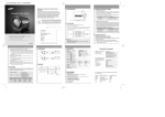
1
Apex ID
TM
Instructions
For Use
TAB LE OF CONTENTS
FI G U RES
English3
Français12
Deutsch21
Español30
Italiano39
Português48
Nederlands57
Figure 1.1
Figure 1.6
Dansk66
Norsk75
Suomi84
Svenska93
Česky
102
Magyar
111
Polski120
Русский
129
Hrvatski jezik
138
Figure 1.2
Figure 1.7
Srpski147
Slovensky
156
Eesti165
Lietuviškai174
Română
183
Türkçe192
Ελληνικα
201
繁體中文
210
한국어
219
Figure 1.3
Figure 1.8
Figure 1.4
Figure 1.9
日本語
228
237
Figure 1.5
F IGUR E S
Figure 2.1
Figure 2.9
Figure 2.8
Figure 2.7
Figure 2.3
Figure 2.6
Figure 2.2
Figure 3.3
Figure 2.12
Figure 2.10
Figure 2.11
Figure 2.4
Figure 2.13
Figure 2.14
Figure 3.4
Figure 2.5
Figure 3.5
Figure 3.1
Figure 3.2
Figure 3.6
1
F IGUR E S
Figure 4.1
Figure 4.5
Figure 4.8
Figure 4.2
Figure 4.6
Figure 4.9
Figure 4.3
A
B
C
Figure 4.7
Figure 4.4
Figure 4.10
Figure 5.2
A
Anatomical
apex or
apical
foramen
Radiographic
apex
Physiological apex
or apical constriction
B
C
A) Distance between radiographic
apex and anatomical apex
B) Distance between physiological
apex and anatomic apex
C) Distance between radiographic
apex and physiological apex
Figure 5.1
2
This manual provides instruction on how to measure the working length of root canals using the Apex ID
Electronic Apex Locator.
•
•
•
This instruction manual has been prepared for use by dental professionals.
This manual and the product may be subject to change without notice if required.
The product has been tested for electromagnetic application test compliance with EN60601-1-2 and is designed to protect against harmful interference when installed and operated according to instructions. This product could produce, use, and discharge wireless wavelength energy; and it may cause harmful interference with other equipment nearby. In this event, the user should resolve the interference using one or more of the recommendations described below:
o Increase the distance between the Apex ID and the device which is experiencing interference.
o Reinstall and restart the Apex ID again.
o Contact your distributor or SybronEndo.
SAFETY PRECAUTIONS
Please read this manual carefully. The purpose of this instruction manual is to provide effective & safe
operation of the Apex ID for users and patients.
SAFE OPERATION
Symbols: This instruction manual contains various symbols to assist the operator in correct and safe operation of
the device and to protect against injury, damage or loss of property. The symbols and meanings are as follows:
Keep
Dry
Type B
Applied
Part
12
DANGER Rx ONLY
Temperature Dispose
Consult
This
Stack 12
Could0120
result
in
injury
or death.
Instructions
Of
Side
Up Maximum
-20C to 50C
Caution
For Dental
Use Only
For Use
Humidity
5% to 90%
Properly
Handle
With
Care
Keep
Dry
Type B
Applied
Part
12
CAUTION Rx ONLY
Consult
Handle
Caution
This
Stack 12 Temperature Dispose
Could
result
in injury
orOf death.
With
For0120
Dental Side Up Instructions
Maximum
-20C to 50C
For Use
Use Only
Humidity
5% to 90%
12
DANGER
0120on
use
Temperature Dispose
Consult
Instructions -20C to 50C
Of
For Use
Properly
Humidity
5% to 90%
Handle
With
Care
Keep
Dry
Type B
Applied
Part
Caution
For Dental
Use Only
This
Side Up
Properly
Care
Keep
Dry
Type B
Applied
Part
12
NOTICE Rx ONLY
Caution result
This
Stack
12
May
in
injury
or death.
For Dental Side Up Maximum
Use Only
May result in incorrect data.
Rx ONLY
Stack 12
Maximum
• Do not
patients with pacemakers.
• Do not use with electrosurgery devices.
• Products or parts which have not been approved by SybronEndo shall not be connected or attached to this
product. Use of un-approved products or parts may result in malfunction of the device and injury to the patient.
• Do not use this device in the presence of oxygen-oxidized substances, nitrogen-oxidized substances or combustible anesthetic mixtures.
12
CAUTION
0120
Temperature Dispose
Consult
Instructions -20C to 50C
Of
For Use
Properly
Humidity
5% to 90%
Handle
With
Care
Keep
Dry
Type B
Applied
Part
Caution
For Dental
Use Only
This
Side Up
Rx ONLY
Stack 12
Maximum
“Caution: Federal law restricts this device to sale by or on the order of a dentist.”
• This device is not waterproof. Exposure to moisture could result in electric shock or damage to the device.
• Do not disassemble the device. Disassembly and touching the inside of the device could result in electric shock
or burn. (If you disassemble the product intentionally, warranty shall not be honored irrespective of guarantee
period.)
• Disassembly or repair should only be done by those authorized by SybronEndo.
• This product is for dental operative use only.
• Confirm the device is operating normally prior to use.
• When the volume of battery is low, discontinue use and replace the batteries.
• Do not try to use in high humidity conditions.
• Protect the device from the effects of atmospheric pressure, wind, sun and salt.
• Do not use where explosive products or gases are stored.
• Stop using if not operating correctly.
• Not indicated for any use except for measuring the working length of root canals.
3
12
NOTICE
Temperature Dispose
Consult
Instructions -20C to 50C
Of
For Use
Properly
Humidity
5% to 90%
Handle
With
Care
Keep
Dry
Type B
Applied
Part
Caution
For Dental
Use Only
This
Rx ONLY
Stack 12
Side Up Maximum
0120 is for use by dental professionals only.
• This product
• To avoid electrical shock or explosion, keep the device away from high temperature or high humidity. Keep the
metal parts of this product away from conductors. Fire, electric shock, or damage may result.
• Do not put heavy items on the device. Fire or electric shock may result.
• Confirm all measurements of canal length with radiographs.
• Blocked root canals cannot be measured correctly.
• When you give this device to others, include the Instructions For Use.
• Remove the batteries if the Apex ID device is not likely to be used for sometime.
Label maintenance and repair:
• The label for notice or caution shall be maintained soundly with regular inspection.
• Replace: If the label for notice or caution has been lost or damaged, please contact SybronEndo for replacement.
1 – IND I CATIONS F OR U SE AN D PRI N CI PLE O F O PER AT I O N
1.1 – Indications for use
Apex ID is an Electronic Apex Locator designed for use in
measuring the working length of root canals.
Keep
Dry
12 Rx ONLY
NOTICE Use
the device to measure the working
Caution
This
Stack 12
length
of
For Dental Side
Up root
Maximumcanals only.
Type B
Applied
Part
Use Only
1.2 – Principle of operation
Micro signals consisting of dual frequencies sent from
the unit return to the unit after travelling along the electric
circuit that is composed of: unit - probe cord – file holder file - patient - lip holder - probe cord. The impedance of the
electric circuit may be changed depending on the distance
between the end of a file and the apex of the root canal,
which results in a change in the micro signals that are
input back into the unit. The microprocessor of the unit
calculates the change in micro signals to convert the
difference into a distance value, which will be displayed
on the Apex ID LCD display.
2 – DE V I CE CONTENTS AN D FU N CTI O N S
2.1 – Device contents and functions
Contents of product:
Apex ID Unit (1) – Fig 1.1
AAA Alkaline Batteries (3) – Fig 1.2
Stand (1) – Fig 1.3
Lip Hooks (5) – Fig. 1.4
File Holder A (1) – Fig 1.5
File Holder B (2) – Fig 1.6
Instructions For Use (1) – Fig 1.7
Probe Cord (1) – Fig 1.8
Checker (1) – Fig 1.9
2.2 – Accessories and their functions
4
Name
Functions
Probe cord – Fig 1.8
Connects between the Apex ID & file holder & Lip Hook
Lip Hook – Fig 1.4
For contact to patient’s lip
File holder A – Fig 1.5
Touch to file (designed for molar teeth)
File holder B – Fig 1.6
Holds File
Checker – Fig 1.9
Confirms that the Apex ID is functioning correctly
2.3 – The features of the Apex ID and their functions
Feature
Functions
LCD Screen – Fig 2.1
Shows the status of settings and indicates the distance
between the end of file inserted in root canal & root apex
Control panel – Fig 2.2
Select power ON/OFF & control functions
Stand – Fig 2.3
Placing the Apex ID on a counter
Battery compartment – Fig 2.4
Contains batteries 1.5V x 3 (DC 4.5V).
Probe cord jack – Fig 2.5
Connect to probe cord for measuring working length of
root canal
Up button (
) – Fig 2.6
Down button
SET(
) – Fig 2.7
SET
Setting button ( SETSET ) – Fig 2.8
Power button (
) – Fig 2.9
Push the button to increase the root apex standard value
by 0.1 and the volume of buzzer is increased 1 step up
Push the button to decrease the root apex standard value
by 0.1 and the volume of buzzer is decreased 1 step down
Push the button to fix the setting mode
Push the button to turn the unit ON/OFF
SN
Buzzer volume signal – Fig 2.10
Indicates the volume of the Buzzer
Graph signal – Fig 2.11
Graph shows the distance between the end of file and
root apex
Battery signal – Fig 2.12
Indicates remaining battery life
Root apex signal – Fig 2.13
Indicates when file has reached the apical foramen, or
the “0” point set by the operator
Numeric signal – Fig 2.14
Indicates the distance between the end of file & root apex
REF
3 – P RO DUCT SYMBOLS
SN
Serial Number
REF
EC REP
Authorized Representative in the European Community
Part Number
Consult Instructions for Use
Manufacturing Date
CSA Marking
CE Marking
Dispose of Properly
Type B Applied Part
Manufacturer
Caution
EC REP
5
4 – B E FORE USE
4.1 – Check contents
• Confirm that all the components listed in the Contents are in the box before using the device for the first time. (Please refer to Kit Contents in section 2)
• Please check the exterior of the device for damage.
Keep
Dry
12 Rx ONLY
NOTICE SybronEndo
shall not be responsible
Caution
This
Stack 12
for
any
damage
caused by misuse of the product.
For Dental Side Up Maximum
Type B
Applied
Part
Use Only
4.2 – Check connection between probe cord and
file holder
Insert lip hook and file holder B into probe cord [Fig 3-1].
Insert probe cord into probe cord jack of the main unit.
[Fig 3-2]
After turning on the power, make sure there is a complete
circuit by touching file holder B to the lip hook. The screen
will show all bars lit and a dashed line on the lower light of
SET
the screen [Fig. 5.1]. The tone will be steady.
Note: If the power button ( ) doesn’t work, make sure
that the insulation plastic is completely removed from
the battery cover in the back of the product. Remove the
insulation plastic piece before use. [Fig 3-4]
SET
4.3 – Performance inspection with checker
Power on by pushing power button ( ). [Fig 3-5]
Plug in Checker (to the probe cord jack) provided in the
original packaging and see if the value on the LCD screen
is ‘0.5’. [Fig 3-6]
If ‘0.5’ is displayed on the LCD screen, the unit is ready
for clinical usage.
5 – S E T UP AND USE
5.1 – Probe cord connection
Connect the file holder and lip hook to the probe cord.
[Fig 3-1] The probe cord should be connected to the probe
cord jack of the main unit. [Fig 3-2]
5.2 – Setting the standard value for root apex SET
Turn on the product by pushing the power button ( ).
[Fig 4-1] The position of the file tip is shown by the canal
length indicator bar on the display. Working Length: The 0.5
reading indicates that the tip of the file is at or very near
the apical construction (physiological foramen). [Fig 5.2]
6
Push the up button ( ) and down button (
ously for about 3 seconds. [Fig 4-2]
) simultaneSET
SET by pushing the up button (
Set at ‘0.0’ at this point
) or
down button ( ). [Fig 4-2] Change back by following the
same process.SET
SET
Push the setting button ( SET ) then the desired value of the
root apex shall be fixed. [Fig 4-3]
Keep
Dry
12 Rx ONLY
NOTICE The
standard value for the apex of
Type B
Caution
This
Stack 12
Apex
ID
is
set as 0.0 at the factory. This value means
Applied For Dental Side Up Maximum
Part
Use Only
that the file has reached the anatomical foramen.
[Fig 5.2]
5.3 – Setting of the buzzer volume
SET
Turn
on the Apex ID by pushing the power button
( ). [Fig 4-1]
Push the up button ( ) and down button ( ), simultaneously for about 3 seconds, and push settingSETbutton ( SET )
once. [Fig 4-4]
SET
Temperature Dispose
Consult
Instructions -20C to 50C
Of
For Use
Properly
Humidity
5% to 90%
Handle
With
Care
Keep
Dry
0120
Adjust the volume of the
buzzer by pressing the up button
( ) or the down button ( ). [Fig 4-2]
SET ) to keep the set volume.
Push the setting button ( SET
Temperature Dispose
Consult
Handle
Keep
[Fig
4-3]
Instructions -20C to 50C
Of
With
Dry
0120
SET
For Use
Humidity
5% to 90%
Properly
Care
5.4 – Measuring the working length of the root canal
SET
Turn
on the Apex ID by pushing the
power
buttonHandle
Temperature Dispose
Consult
Instructions -20C to 50C
Of
With
0120
For Use
Properly
Care
( ). [Fig 4-1]
Humidity
Keep
Dry
Continue inserting the file to -0.1 (if the standard value of
the root apex is set at 0.0) then move the file back until
0.0 is displayed on the screen. This helps to confirm the
location of the apex. [Fig 4-8 ~ Fig 4-10]
After positioning the rubber stop of file on the tooth at the
reference point the file should be removed from the canal.
Measure the working length from the tip of the file to the
rubber stop with a ruler. After positioning the rubber stop
on the file to a reference point, the file should be removed
from the tooth.
12 Rx ONLY
NOTICE The
measurement result shown by
Caution
This
Stack 12
the
Apex
and the length of file may vary depending
For Dental
Side Up ID
Maximum
Use Only
on the operator’s angle of view.
Type B
Applied
Part
12 Rx ONLY
The insertion
angle of the file after enlarging the
Caution
This
Stack 12
canal
may
vary
For Dental Side Up Maximum from the original working length
Use Only
measurement angle.
Type B
Applied
Part
12
Re-confirm Rx
theONLY
working length after enlarging
Caution
This
Stack 12
the
For Dentalcanal.
Side Up Maximum
Type B
Applied
Part
Use Only
5% to 90%
SET
Keep
Dry
Turn off the Apex ID by pushing the power button ( ).
The power will automatically shut off after 1 minute of
non-use. The working length should be confirmed by
radiograph.
12 Rx ONLY
NOTICE Before
use, sterilize the lip hook
Type B
Caution
This
Stack 12
a Upsteam
Applied using
For Dental Side
Maximum sterilizer at 121°C for 30 minutes.
Part
Use Only
Place the lip hook on the patient’s lip. [Fig 4-5]
Keep
Dry
12 Rx ONLY
Consult
Dispose
Handle
NOTICE Place
the lip hook
onTemperature
the
Instructions
Of
With
-20C
to 50C opposite
0120
For Use
Properly
Care
Humidity
Type B
Caution
This
Stack 12
5% to 90%
mouth from the tooth being
measured.
Applied side
For Dentalof
Sidethe
Up Maximum
Part
Use Only
Use with Stainless Steel hand file.
Keep
Dry
Insert the file into the canal. [Fig 4-6]
12 Rx ONLY
NOTICE A radiograph
may show a different
Caution
This
Stack 12
measurement
For Dental Side Up Maximum result than the Apex ID. This is not an
Use Only
indication of malfunction by the unit or the x-ray.
Often the apical foramen is located coronal to the
radiographic apex. [Fig 5.2] Another possibility is the
angle of the x-ray beam and film may be off angle to
the perpendicular.
Type B
Applied
Part
Attach the file holder B to the file (If using holder A, touch
the file below the handle with the file holder). [Fig 4-7]
Insert the file slowly into the root canal while checking the
graph and the number value on the screen. Stop insertion
when the distance between the file and root apex reaches
the standard value of the root apex (pre-set factory setting
at 0.0mm or your chosen value). As the file nears the
apical constriction, the unit will beep more rapidly. When
the apex is reached the file is touching the periodontal
membrane and a red bar will appear at the “Apex” on
the screen. As it goes past the apical constriction, the
frequency of beeps increases until the screen reads “-0.5.”
Then the sound will remain steady and the entire screen
will flash.
7
6 – G U I DE F OR ACCURATE M EASU REM EN T
Turn on the Apex ID prior to use.
Plug the Checker [Fig 1-9] (provided in the original packaging)
into the probe cord jack [Fig 2-5] and confirm the value on
the LCD screen is 0.5.
It is recommended to insert the file into the canal first and
then connect the file to the file holder.
If the signals do not change as the file approaches the
APEX, it is possible the root canal is too dry; therefore it
should be filled with an irrigant.
Necrotic tissue or other matter in the root canal may affect
accuracy. It is advisable to take several measurements
during enlargement of the canal.
Start with a larger file at first. If the APEX indication (graph
and numeric signal on the screen) does not reach the
APEX, gradually try a smaller file to measure the working
length of the root canal.
To minimize error, it is recommended the working length
be measured more than twice.
If root canals within a tooth are connected, as in the case
of multiple root canals with anastomoses or cracks, missmeasurement is possible. It is recommended to verify the
tooth’s anatomy radiographically.
Contact with metal restorations by the file during
measurements may result in errors.
Remove blood or exudate from the canal before
measurement.
In cases where the foramen is not completely formed or
the foramen has been overly expanded, the measurement
value of the working length may be shorter than the actual
measurement value.
7 – M A I NTENANCE AND STO RAG E
7.1 – Sterilization
The ‘Lip Hook’ and ‘File holder A’ should be sterilized at
121°C for 30 minutes with high-pressure steam.
7.3 – Method used to validate recommended
sterilization method:
Sterility Assurance Level (SAL): 10-6
1) Sterilization validation samples are wrapped with BIs.
2) 3 times of sterilization cycles as a half cycle are carried
out at 121°C for 15 minutes.
3) 1 time of sterilization cycle as a full cycle is carried out
at 121°C for 30 minutes.
4) Incubate BIs at 55~60°C for 7days.
The ‘File holder B’ should be sterilized at a temperature
of 121°C for 30 minutes with high-pressure steam in a
sterilization pouch, then dried at least 10 minutes after
sterilization.
Keep
Dry
Keep
Dry
Type B
Applied
Part
Caution
For Dental
Use Only
12 Rx ONLY
CAUTION Parts
used in direct intraoral
This
Stack 12
contact
are to be steam sterilized.
Side Up Maximum
7.4 – Sterilizer used for validation
• Manufacturer: DAIHAN LABTECH CO., LTD
• Model name: LAC-5105SP
• Serial No. : 20101202138
• Control No. : TE-10-23
• Valuable room: 100 liter
• Power supply: AC 220V, 50/60Hz
• Pressure: 2.6kgf/cm2
• Range of sterilization temperature: 105°C~135°C
12 Rx ONLY
NOTICE It is
highly recommended to place
Caution
This
Stack 12
File
B in a sterilization pouch for autoclaving.
For Dentalholder
Side Up Maximum
Use Only
• The metal of the File holder B may be corroded
when it is in direct contact with steam.
• Temperature should not exceed 135°C during
sterilization as the product may be damaged.
Type B
Applied
Part
7.5 – Cleaning
Clean the Apex ID or probe cord with dry gauze and a
small amount of ethanol. Any ethanol left on the product
after cleaning should be completely wiped off with a dry
cloth.
7.2 – Recommended sterilizer type
• Sterilizer: Vacuum type (B)
• Sterilization temperature: 121°C,
• Sterilization time: 30min
0120
8
Temperature Dispose
Consult
Instructions -20C to 50C
Of
For Use
Properly
Humidity
5% to 90%
Handle
With
Care
Keep
Dry
12 Rx ONLY
CAUTION Use
protective sleeves on the cords
Caution
This
Stack 12
and
ID during operation, followed by removal
For
Dental Apex
Side Up Maximum
Use Only
of the sleeve and wiping with alcohol after operation.
Type B
Applied
Part
Keep
Dry
12 Rx ONLY
CAUTION Do
not use the Apex ID when wet
Type B
Caution
This
Stack 12
with
ethanol.
There is a possibility of electric shock
Applied For Dental Side Up Maximum
Part
Use Only
or product damage.
-20~50°C, atmospheric pressure 70~106 Kpa and relative
humidity 5~90%.
7.7 – Disposal
Dispose of the product in accordance with your local
waste disposal regulations and/or laws
7.6 – Operating, Storage, Transport
The Apex ID should be operated in temperatures ranging
from 10~40°C, atmospheric pressure 70~106 Kpa
and relative humidity 30~75%. The Apex ID should be
stored and transported in temperatures ranging from
8 – T RO UBL E SHOOTING
If any problems occur, refer to the table below. If there are any further problems or issues please contact your distributor
or SybronEndo.
Problem
Possible Causes
Solutions
No power
Low Battery / No Battery
Replace the batteries
No power
Battery replacement does not solve
the problem
Check the connection to the batteries
No buzzer sound
No sound setting
Adjust the buzzer volume
Power ON, but no measurements
show
Probe cord disconnected from the
main unit
Check the connection of Probe cord
and the main unit
Power ON, but not measured
File holder disconnected from Probe
cord
Check the connection of file holder
and Probe cord
9 – P RODUCT SPECIF ICATI O N S
• Rated voltage: DC4.5V (1.5V Alkaline Battery AAA x 3EA)
• Input current: less than DC 60mA
• Power consumption: less than 0.27VA
• Patient auxiliary current: less than AC 10µA
• Oscillation frequency: 500Hz ±0.2Hz, 5kHz ±0.002kHz
• Size: W70mm ±1mm x D25mm ±1mm x H100mm
±1mm
• Weight: 390g ±15g (including stand, except battery)
• Protection type and level against electric shock: Type B
applied part
• Internally powered equipment, Ordinary equipment
(IPX0)
• Continuous operation time: 62hours (at 1250mAh
Battery x 3EA)
10 – G U I DANCE AND M AN U FACTU RER ’ S DECLARAT I O N
Guidance and manufacturer’s declaration – electromagnetic emissions
The Apex ID is intended for use in the electromagnetic environment specified below. The customer or the user of the
Apex ID should assure that it is used in such an environment.
Emissions test
Compliance
Electromagnetic environment - guidance
RF emissions CISPR 11
Group 1
The Apex ID uses RF energy only for its internal functions. Therefore, its
RF emissions are very low and are not likely to cause any interference in
nearby electronic equipment.
RF emissions CISPR 11
Class A
The Apex ID is suitable for use in all establishments including domestic and
those directly connected to the public low-voltage power supply network
that supplies buildings used for domestic purposes.
9
Guidance and manufacturer’s declaration – electromagnetic immunity
The Apex ID is intended for use in the electromagnetic environment specified below. The customer or the user of the
Apex ID should assure that it is used in such an environment.
Immunity test
IEC 60601test level
Compliance level
Electromagnetic environment – guidance
Electrostatic
discharge (ESD)
IEC 61000-4-2
±6kV contact
±8kV air
±6kV contact
±8kV air
Floors should be wood, concrete or ceramic tile.
If floors are covered with synthetic material, the
relative humidity should be at least 30%.
Electrical fast
transient/burst
IEC 61000-4-4
±2kV for power
supply lines
±1kV for input/
output lines
±2kV for power
supply lines
Main power quality should be that of a typical
commercial or hospital environment.
Surge IEC 61000-4-5
±1kV differential
mode
±2kV common
mode
±1kV differential
mode
±2kV common
mode
Main power quality should be that of a typical
commercial or hospital environment.
Voltage dips, short
interruption, and
voltage variations on
power supply input
lines IEC 60601-4-11
<5% UT (>95% dip
in UT) for 0.5 cycle
40% UT (60% dip in
UT) for 5 cycles
70% UT (30% dip
in UT)
< 5% UT (>95% dip
in UT) for 5s
<5% UT (>95% dip
in UT) for 0.5 cycle
40% UT (60% dip
in UT) for 5 cycles
70% UT (30% dip
in UT) < 5% UT
(>95% dip in UT)
for 5s
Main power quality should be that of a typical
commercial or hospital environment. If the user
of the Apex ID requires continued operation
during power main interruptions, it is
recommended that the model Apex ID be
powered from an uninterruptible power supply
or battery.
Power
frequency(50/60 Hz)
IEC 61000-4-8
3 A/m
3 A/m
Power frequency magnetic fields should be at
levels characteristic of a typical location in a
typical commercial or hospital environment.
Conducted RF
IEC61000-4-6
3 V/m
150 kHz to 80MHz
3 V/ms
150 kHz to 80MHz
Radiated RF
IEC 61000-4-3
3V/m
80 MHz to 2.5GHz
3V/m
80 MHz to 2.5GHz
Portable and mobile RF communications
equipment should be used no closer to any part
of the Apex ID, including cables, than the
recommended separation distance calculated
from the equation applicable to the frequency of
the transmitter.
Note: UT is the A.C. mains voltage prior to application of the test level.
Note: At 80MHz and 800MHz, the higher frequency range applies.
Note: These guidelines may not apply in all situations. Electromagnetic
propagation is affected by absorption and reflection from structures,
objects and people.
Field strengths from fixed transmitters, such as base stations for radio
(cellular/cordless) telephones and land mobile radios, amateur radio,
AM and FM radio broadcast and TV broadcast cannot be predicted
theoretically with accuracy. To assess the electromagnetic environment
due to fixed RF transmitters, an electromagnetic site survey should be
considered. If the measured field strength in the location in which the
Apex ID is used exceeds the applicable RF compliance level above, the
Apex ID should be observed to verify normal operation. If abnormal
performance is observed, additional measures may be necessary, such
as re-orienting or relocating the Apex ID.
b
Over the frequency range 150kHz to 80MHz, field strengths should be
less than [V1] V/m.
10
SN
REF
Recommended separation distance
d=[3.5/V1]√P
EC REP
d=[3.5/E1]√P 80MHz to 800MHz
d=[7/E1]√P 800MHz to 2.5GHz
Where P is the maximum output power rating of
the transmitter in watts (W) according to
the transmitter manufacturer and d is the
recommended separation distance in meters (m).
Field strengths from fixed RF transmitters, as
determined by an electromagnetic site survey, a
should be less than the compliance level in each
frequency range.b
Interference may occur in the vicinity of
equipment marked with the following
symbol:
11 – Q UAL ITY GUARANTEE AN D RESPO N SI BI LI TY
Quality Certificate
Product Name: Electronic Apex Locator
Model: Apex ID
Consumer Date of Purchase:
Guarantee period: Device - 3 years / Accessory - 6 Months
Manufactured for: SybronEndo
Contact: 714.516.7979
Address: 1332 S Lone Hill Ave., Glendora, CA 91740-5339
If a problem has occurred during the guarantee period due to manufacturing or natural failures please contact SybronEndo.
Warranty service shall be provided without charge during the guarantee period.
12
NOTICE
Temperature Dispose
Consult
Instructions -20C to 50C
Of
For Use
Properly
Humidity
5% to 90%
0120
WARRANTY
AND EXCLUSIONS
Handle
With
Care
Keep
Dry
Type B
Applied
Part
Caution
For Dental
Use Only
This
Side Up
Rx ONLY
Stack 12
Maximum
Warranty
SybronEndo warrants the Apex ID electronic apex locator to be free from defects in materials and workmanship for a
period of 3 years from the original date of purchase, and consumables (excluding batteries) for 6 months from date of
purchase in accordance with SybronEndo’s warranty regulations. If the Apex ID shows any defect within the specified
warranty period that are not excluded from this warranty, SybronEndo shall, at its discretion, either replace or repair
Apex ID using suitable new or reconditioned parts. In the case other parts are used which constitute an improvement,
SybronEndo may, at its discretion, charge the customer for the additional cost of these parts. If the warranty claim
provides to be justified, the product will be returned to the user freight prepaid.
Warranty claims other than those indicated herein, are expressly excluded.
Exclusions
Damages and defects caused by the following conditions are not covered by the warranty:
• Improper handling/disassembly/modifying, neglect or failure to operate the unit in compliance with the instructions
given in the Instruction for Use/User Manual.
• Force majeure or any other condition that is beyond the control of SybronEndo.
• This device is manufactured for the uses specified in this Instruction for Use. SybronEndo shall not be responsible
for any damages caused by customer misuse or uses other than those specified.
Responsibility
SybronEndo shall not be responsible for damages or injuries caused by any of the following:
• Use by unauthorized personnel.
• Changes to or modifications of the device.
• Use of other manufacturer’s devices or parts with the Apex ID.
• Use of unapproved parts or repair of the device by unauthorized parties.
• Disregard of the care or cautions listed in the instruction manual.
• Use of the device for any applications not included in the instruction manual.
• Use of a power supply other than that specified in the instruction manual.
• Fire, flood, lightning or from natural disasters
• Customer carelessness or intentional misuse.
11
Apex ID
TM
Manufactured for | SybronEndo
1332 S. Lone Hill Avenue, Glendora, CA 91740 U.S.A.
714.516.7979 sybronendo.com
MADE IN KOREA
Manufacturer
EC REP
European
Representative
S-Denti Co., Ltd
Rm 607, 612 Byucksan Digital Valley 6, 219
Gasandigital 1-ro, Geumcheon-gu
Seoul, 153-803, Korea
KKC
3 Rue des Rosiers, 92340 Bourg la Reine
France
0120
007-0167 Rev. C