1
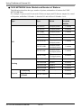
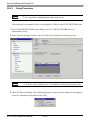
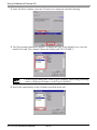
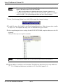
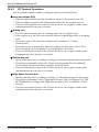
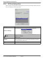
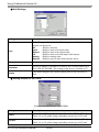
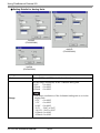
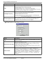
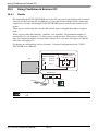
Using FlexNetwork External I/O 30.4 Using FlexNetwork External I/O 30.4.1 Details By connecting the FLEX NETWORK unit to the GP, you can use the display unit to control remotely located external I/O. In addition, you can control other things besides inputs and outputs. You can also add multiple FLEX NETWORK units to increase the number of I/O points. There are two connection lines for the unit and the same communication data is output to both. When you use either line both line 1 and line 2 are available. The maximum number of connectable I/O unit stations is 31 when you are using one line. When you are using two lines, the maximum number of connectable stations is 63. One line will support 31 and the other line will support 32. For details on configuration, refer to Section 1.1 System Configurations in the "FLEX NETWORK Users Manual". I/O Screen Terminal # Address Sensor A 0 Sensor B 1 GP Logic Program Sensor A Lamp A Lamp A Q0 Lamp A FlexNetwork 0 1 Q0 Lamp A Sensor A Sensor B External I/O • A proprietary cable is needed to connect the FLEX NETWORK unit to the GP. GP-Pro EX Reference Manual 30-13 Using FlexNetwork External I/O FLEX NETWORK Units: Models and Number of Stations The following describes the type, number of points, and number of stations for FLEX NETWORK units. For example, if you use an I/O unit with 32 discrete inputs and 32 discrete outputs for a total of 64 points, and define S-Number 1, then the I/O unit will use S-Number 1 to 4. Type I/O Analog Special Number of Occupied Stations Type Points FN-X16TS 16 input points 1 station FN-X32TS 32 input points 2 stations FN-Y08RL 8 output points 1 station FN-Y16SK 16 output points 1 station FN-Y16SC 16 output points 1 station FN-XY08TS 8 input points 8 output points 1 station FN-XY16SK 16 input points 16 output points 1 station FN-XY16SC 16 input points 16 output points 1 station FN-XY32SK 32 input points 32 output points 4 stations FN-AD02AH 2chA/D 1 station FN-AD04AH 4chA/D 4 stations FN-DA02AH 2chD/A 1 station FN-DA04AH 4chD/A 4 stations Positioning FN-PC10SK - 4 stations High Speed Counter FN-HC10SK41 - 8 stations GP-Pro EX Reference Manual 30-14 Using FlexNetwork External I/O 30.4.2 Setup Procedure • Please refer to the Settings Guide for details. ) "30.3.3 [I/O Driver Settings] Setting Guide" (page 30-12) The following is an example of how to use digital I/O (DIO) in the FLEX NETWORK unit. 1 Select AGP-XXXXX-FN1M as the display unit. The FLEX NETWORK driver is automatically set up. 2 In the [System Settings] window, select [I/O Driver] to display the following screen. • If the [System Settings] tab is not displayed in the workspace, on the [View (V)] menu, point to [Workspace (W)], and then click [System Settings (S)]. 3 Click [I/O Driver Settings]. The following dialog box appears. In the dialog box that appears, select the Transmission Speed and click [OK]. GP-Pro EX Reference Manual 30-15 Using FlexNetwork External I/O 4 In the I/O Driver window, select the I/O unit to be configured, and click [Setting]. 5 The [Unit Settings] dialog box appears. To change the type, in the [Model] area, select the model of I/O unit. (For example, [Input and Output] and "FN-XY16SK"). • When using an analog unit, set the Type to [Analog]. When using positioning units or a high-speed counter, set the Type to [Special]. 6 Specify the same number as the S-Number specified on the unit. GP-Pro EX Reference Manual 30-16 Using FlexNetwork External I/O • You can specify the S-No from 1 to 63. However, you cannot duplicate the same S-No in the same FLEX NETWORK. )" FLEX NETWORK Units: Models and Number of Stations" (page 30-14) • To define detailed settings in the I/O unit, click [Details], make your changes, and click [OK]. (The positioning unit does not have detail settings.) 7 In the [Unit Settings] dialog box, click [OK] to apply the changed settings. 8 To add I/O units, click [Add]. In the [Unit Settings] dialog box, follow the procedure similar to steps 5 to 7 to complete the setup. You can add different types of units. 9 After completing the device settings for the FLEX NETWORK, map the addresses to the I/O terminals. Click [I/O Screen] to set up I/O terminals. • You can also display the I/O Screen from the [Screen List] window. 10 Map an address (variable) to each terminal. The following describes how to map addresses. ) "30.1.2 Mapping Addresses (variables) to I/O Terminals" (page 30-3) GP-Pro EX Reference Manual 30-17 Using FlexNetwork External I/O 30.4.3 I/O Terminal Operations An I/O terminal to which an address is mapped operates as described below. Input and output (DIO) • When the input terminal turns ON, the address mapped to the terminal turns ON. • When the address mapped to the output terminal turns ON, the terminal turns on. • If a power interruption occurs on the I/O unit, the driver can recognize it and resume communications after the power resumes. Analog unit • The A/D conversion unit converts an analog input value to a digital value. • In the opposite way, the D/A conversion unit converts a digital input value to an analog value. • For details, refer to "Flex Network Analog Unit User Manual, 2.3 Analog Characteristics". • For details on how to acquire data values according to the filter type, refer to "Flex Network Analog Unit User Manual, 2.4 Analog/Digital Conversion". • If a power interruption occurs on the I/O unit, the driver can recognize it and resume communications after the power is resumed. Positioning unit • Specifies the data value by reading or writing by a command, and determines the position. • For details on commands, refer to the "Single-Axis Positioning Unit User Manual", sections titled "FlexNetwork Driver Settings" and "RUN Data". • If a power interruption occurs on the I/O unit, the driver can recognize it and resume communications after the power is resumed. High-Speed Counter Unit • Specifies the data value by reading or writing by a command, and operates the counter. • For details on commands, refer to "High-Speed Counter Unit Users Manual 5.1 FLEX NETWORK Driver Settings" and "High-Speed Counter Unit Users Manual 5.2 Data Settings". • If a power interruption occurs on the I/O unit, the driver can recognize it and resume communications after the power is resumed. GP-Pro EX Reference Manual 30-18 Using FlexNetwork External I/O 30.4.4 [I/O Driver] Settings Guide When using the AGP-XXXXX-FN1M display unit, in the System Settings window click [I/O Driver] to display the following window. Setting Description This button displays the [I/O Driver Settings] dialog box. I/O Driver Settings Communication Speed Add Settings Delete I/O Screen Select the communication speed for FLEX NETWORK as either [6Mbps] or [12Mbps]. Adds I/O units. Click the button. The [Unit Settings] dialog box appears. Use the dialog box to select your I/O unit and define I/O details. ) " Unit Settings" (page 30-20) Deletes I/O units. Click the button to switch to the I/O screen. GP-Pro EX Reference Manual 30-19 Using FlexNetwork External I/O Unit Settings Setting Description Type Select the type of unit from the following options. Only relevant models are displayed. All : Displays all units. Input : Displays units with inputs only. Output : Displays units with outputs only. I/O : Displays units with both inputs and outputs. Analog : Displays analog units. Special : Displays special units other than the above. Information Displays details for the I/O unit settings. S-Number Specify a number (S-Number) to identify the I/O unit connected to the FLEX NETWORK. The settings range from 1 (default) to 63. Details This button displays the [Details] dialog box for the selected I/O unit. Setting Details for DIO Units 32 input and output points (FN-XY32SK) Setting Description Input Select the variable type for the input from either [Bit] or [Word]. The 8, 16, or 32 points change depending on the type of I/O unit. Output Select the variable type for the output from either [Bit] or [Word]. The 8, 16, or 32 points change depending on the type of I/O unit. GP-Pro EX Reference Manual 30-20 Using FlexNetwork External I/O Setting Details for Analog Units 2chA/D (FN-AD02AH) 4chA/D (FN-AD04AH) 2chD/A (FN-DA02AH) Setting Mode Description Select [2CH] or [1CH] in the 2-channel analog unit. Set the range (resolution) in the 2-channel analog unit. 0-10V : 0 to 4095 0-20mA : 0 to 4095 4-20mA : 0 to 4095 Range • The range (resolution) of the 4-channel analog unit is set in the display unit. 0-5V : 0 to 4095 1-5V : 0 to 4095 0-10V : 0 to 4095 -5-5V : -2047 to 2047 -10-10V: -2047 to 2047 0-20mA: 0 to 4095 4-20mA: 0 to 4095 Continued GP-Pro EX Reference Manual 30-21 Using FlexNetwork External I/O Setting Description Type Select the filter type. 2-channel analog: None, Moving Average 4-channel analog: None, Average, Moving Average For details on filter, refer to Section 2.4 Analog/Digital Conversion, in the "Flex Network Analog Unit User Manual". Sampling Frequency Select the number of samples for A/D conversion. When the filter type is set to [None], this option can be selected. 2-channel analog:2/4/8/16/32/64 4-channel analog:2/4/8/16/32/64/128/256/512/1024/2048/4096/ 8192/16384/32768/65536 Specify whether to remove the maximum and minimum values in Exclude Highest/Lowest the sample data. This option can be selected if the number of samples for A/D conversion is set to 4 or higher. Setting Details for High-Speed Counters (FN-HC10SK) Setting Type Description Select [16-bit UpCounter x 2CH], [32-bit UpCounter], or [32-bit UpDownCounter]. Select the measurement speed. • When setting [Type] to [16-bit UpCounter x 2CH] or [32-bit Measurement rate (pps) UpCounter], select [1K] or [10K]. • When setting [Type] to [32-Bit UpDownCounter], select [Line Driver] or [Open Collector]. Pulse Counter Select the pulse count method from [1 Signal - Multiply by 1 (50kpps)], [1 Signal - Multiply by 1 (200kpps)], [2 Signal - Multiply by 1 (50kpps)], [2 Signal- Multiply by 1 (200kpps)], [2 Signal Multiply by 2 (25kpps)], [2 Signal - Multiply by 2 (100kpps)], [2 Signal - Multiply by 4 (12.5kpps)], or [2 Signal - Multiply by 4 (50kpps)]. Continued GP-Pro EX Reference Manual 30-22 Using FlexNetwork External I/O Setting Counter format Description Select [Linear], [Ring], or [Frequency]. For details on the count method, refer to Section 4.2 Various Functions, in the "High-Speed Counter Unit User Manual". GP-Pro EX Reference Manual 30-23 Using FlexNetwork External I/O GP-Pro EX Reference Manual 30-24