1
Table of Contents
CD-ROM Package Contents ...............................................................................
Description ...........................................................................................................
System Requirements .........................................................................................
Installing GP-PRO/PB III C-Package03 ..............................................................
Viewing GP-PRO/PB III C-Package03 PDF Manuals .........................................
Installing Adobe® Acrobat® Reader 5.0.5 ............................................................
Viewing PDF Manuals .........................................................................................
Project Development Flow ...................................................................................
Prior to beginning project development: ..............................................................
28
28
29
30
30
33
33
34
34
- 27 -
CD-ROM Package Contents
The following items are included in the GP-PRO/PB III C-Package03 package.
Prior to installing this software, use the list below to check that all items are
included. If you find that any items are defective or missing, please contact your
local Pro-face distributor or sales representative for replacement.
Item
Quantity
Disc1
1
Disc2
1
User Registration
Card
1
Setup Guide
(This manual)
1
Remarks
Contains GP-PRO/PB III C-Package03
PDF manual and application.
Contains GP-PRO/PB III C-Package03
sample Parts and ISO symbols.
Contains instructions on installation and
operation of GP-PRO/PB III
C-Package03.
Description
GP-PRO/PB III C-Package03 includes the new GP-PRO/PB III for Windows Ver.
7.0 and Pro-Control Editor Ver. 5.0 software. This single package allows you to
perform a wide variety of tasks, from screen creation and editing to logic programming.
- 28 -
System Requirements
R e q u ire m e n ts
PC
S cre e n
R e s o lu tio n
H a rd D is k
S p a ce
Me m o ry
C D -R OM
D rive
D a ta
Tra n s fe r
C a b le
W in d o w s co m p a tib le typ e
S VGA 8 0 0 x 6 0 0 o r h ig h e r is
re co m m e n d e d .
Min im u m
Ma xim u m
8 5 MB
2 1 5 MB
3 2 MB
Mo u s e
P rin te r
S p a ce re q u ire d fo r in s ta lla tio n .
6 4 MB o r m o re is re co m m e n d e d .
W in d o w s co m p a tib le typ e
GP W -C B 0 2 (s o ld s e p a ra te ly)
m a n u fa ctu re d b y D ig ita l
E le ctro n ics C o rp o ra tio n
U S B D a ta GP W -C B 0 3 (s o ld s e p a ra te ly)
Tra n s fe r m a n u fa ctu re d b y D ig ita l
E le ctro n ics C o rp o ra tio n
C a b le
OS
R e m a rks
P e n tiu m ® II 2 6 6 MH z o r h ig h e r is
re co m m e n d e d .
W in d o w s ® 9 5 /9 8 /ME /2 0 0 0 /XP
®
W in d o w s N T 4 .0 co m p a tib le
W in d o w s co m p a tib le typ e
R S -2 3 2 C co n n e cto rs th a t a re n o t 9 -p in
D -s u b typ e w ill re q u ire a n o p tio n a l
a d a p te r.
Th e o p e ra tio n o f U S B -typ e co n ve rs io n
a d a p to rs is n o t g u a ra n te e d .
R e fe r to th e U S B D a ta Tra n s fe r C a b le
In s ta lla tio n Gu id e .
W in d o w s N T ® 4 .0 re q u ire s S e rvice
P a ck 3 o r h ig h e r
R e q u ire d fo r s o ftw a re in s ta lla tio n .
W in d o w s co m p a tib le typ e
On a PC running Windows® 95, the “Parts Palette’s“ Part selection tabs may not
display correctly. This problem can be fixed by installing “comctl32.dll” in your PC.
This file can be downloaded from the following Internet site:
http://www.microsoft.com/msdownload/ieplatform/ie/comctrlx86.asp.
At this site, click on the “Download 50comupd.exe(x86)” icon to download the
update program.
* As of May 2002, this URL is correct. It is, however, subject to change without
notice.
* After you update your system file, there is the possibility that other applications in
your PC may be affected.
- 29 -
Installing GP-PRO/PB III C-Package03
Prior to Installation
• Be sure to quit all application programs and close (disable) all resident programs, such as virus detection software.
• When using a PC with Microsoft® Windows NT® 4.0 (Service Pack 3 or later),
Microsoft® Windows® 2000, or Microsoft® Windows® XP, install this software in a
User Account that has Administrator privileges.
Installation
Normally, the GP-PRO/PB III C-Package03 installation program starts automatically when Disc1 CD-ROM is inserted into the CD-ROM drive. To complete the
installation process, simply follow the instructions given on each screen.
If, however, the installation program does not start automatically, please do the
following to install the software:
1. With Disc1 CD-ROM inserted in the CD-ROM drive, click the desktop’s [Start]
button and then click [Run].
2. In the text window, enter [X:\INSTALL.EXE] and click [OK]. (Here, "X" represents
your CD-ROM drive’s drive character.)
3. After the installation program starts, simply follow the instructions given on each
screen to complete the installation process.
Viewing GP-PRO/PB III C-Package03 PDF Manuals
GP-PRO/PB III C-Package03 has a total of seven (7) manuals and the table on the
following page explains the contents of each. These manuals are located in Disc1
CD-ROM, however, this manual is not included as a PDF file.
Also, supplemental product explanations and additional or revised feature information is included in the software as a Readme file.
After installation is completed, click the Windows [Start] button, point to [Programs]-[Pro-face]-[ProPB3 C-Package], and click [ReadMe] to view this file.
For detailed Pro-face hardware information, please refer to that product’s User
Manual.
- 30 -
Manual Contents
GP-PRO/PB III C-Package03
Setup Guide (this manual)
Describes software installation and basic
application development steps.
Pro-Control Editor Ver.5.0
Describes the GLC/LT unit's software
settings for variables and commands.
• Explains basic software set up and
operation, and error messages.
Operation Manual
• Explains steps for using GLC variables
created in Pro-Control on GP-PRO/PB III
display screens.
GP-PRO/PB III for Windows Ver.7.0
Describes software features and their use
Operation Manual
in developing GP screens.
Explains the features and set up of "Tags"
Tag Reference Manual
for GP screen features.
Lists the pre-made Parts and
Parts List
standardized symbols provided in
GP-PRO/PB III.
Describes procedures for connecting the
Device/PLC Connection
GP to PLCs, temperature controllers and
Manual
inverters.
User Manual
Note:
• The GP-PRO/PB III Manual describes the procedures for developing GP
screens. The steps for developing GLC/LT screens are identical; simply
substitute "GLC/LT" for "GP.”
- 31 -
• In addition to the manuals listed here, detailed explanations are also
available in each software’s on-line help.
• Disc2 CD-ROM also contains sound files. The [\eng\lib\manual] folder
contains a list of the sound file filenames, and the [\eng\lib\audio] folder
contains the sound files.
Additionally, data layout sheets (Microsoft® Excel files) are installed during the
standard installation of this software. These sheets are useful for specifying device/
PLC registers and designating tag addresses. These files are located in the folder
named "Pro-face\propbwin\sheet”.
For directions on using Microsoft® Excel, please refer to your Microsoft® Excel
documentation and Help features.
Folder Name
Pro-face
\propbwin\sheet
- 32 -
File Name
Device1E.xls
TAG1E.xls,TAG2E.xls,
TAG3E.xls,TAG4E.xls
Contents
List of device
assignments
Tag layout sheet
Adobe® Acrobat® Reader is required to view PDF manuals.
Installing Adobe® Acrobat® Reader 5.0.5
1.Start up your PC, and insert Disc1 CD-ROM into the CD-ROM drive.
2.Click [Start], then [Run].
3.In the text entry box, enter [X:\manual\eng\reader\ar505eng.exe] and click
[OK]. ("X" represents the letter corresponding to your CD-ROM drive.
4.When installation starts, follow the step-by-step instructions that appear. After
installation is completed, Acrobat Reader will start automatically.
Viewing PDF Manuals
1. Insert Disc1 CD-ROM into your PC’s CD-ROM drive.
2. Click [Start], then [Programs], then [Acrobat Reader 5.0].
3. After the program starts, click [Files], and choose [Open].
4. In the [File Name] box, enter the PDF file name and click [Open].
The following PDF files provide access to individual manual files.
GP-PRO/PB III
[X:\manual\eng\gpwmnl_m.pdf]
Pro-Control Editor
[X:\manual\eng\pcemnle.pdf]
("X" represents the letter corresponding to your CD-ROM drive.)
For details on using Acrobat Reader, refer to Acrobat Reader Help.
- 33 -
Project Development Flow
The following steps are the usual “flow” for developing logic programs with
the GP-PRO/PB III C-Package03 software. (It is assumed that GP-PRO/PB III
C-Package03 is already installed.)
Prior to beginning project development:
When using Windows NT ® 4.0, Windows ® 2000, or Windows ® XP, be sure to
use this application only with Administrator level access. Using this application with other access levels may cause faulty operation.
• GP Project Screen Development and Testing
Follow steps 1, 5, 6, 7.
• GLC/LT Screen/Logic Program Development and Testing
Follow steps 1 through 7.
1. Start Up
Start up GP-PRO/PB III C-Package03.
Select the “GP Type” and the “Device/PLC Type”.
2. Assigning Variables to External I/O and Enabling I/O
Here, associate the terminal numbers used for I/O input/output with the
variable you intend to use in the logic program.
3. Create Internal Variables
Create the variables used for internal relays, registers, timers, and counters.
4. Create the Logic Program
Use Pro-Control Editor to create your logic program.
5. Create the GP Project
Use GP-PRO/PBIII to create project screens.
6. Transfer Project and Logic Program to GLC/Check Operation
Transfer the screens and logic programs. Confirm that GP/GLC operates as
designed.
7. Begin Operation
- 34 -
GLC Program Development Example
Here, a simple example is used to explain the procedures, functions and unit operation
required to develop a GLC logic program.
Users developing GLC programs for the first time should find these examples helpful,
as they show how to create a program using a variety of simple devices.
This example assumes you have already installed GP-PRO/PB III C-Package03.
Operating Environment
Main Unit
I/O Unit
Cables
Fan
Sensor
GLC2300T
FN-XY08TS41 (Combining 8-point input/8-point output)
Flex Network communication cable, Data transfer cable
DC 24 V fan
DC 24 V proximity switch
Diagram
Flex Network communication cable
Input to terminal No. 3
Sensor
Output from terminal No. 3
GLC2300T
FN-XY08TS41
Fan
- 35 -
Example Application
This example will create the following screen and logic program.
Explanation
• The fan rotates for five seconds after the GLC screen’s switch is touched.
• To change the fan’s stop time, simply touch the Keypad Input Display (above “12345”) and a popup keypad will appear.
• The fan will stop rotating if a signal is received from the sensor.
- 36 -
1. Starting up the GP-PRO/PB III C-Package03
1.
Click the Windows® desktop’s [Start]
button, and point to [Programs] -> [Proface] -> [ProPB3 C-Package] -> [Project
Manager].
2.
Click the [New] icon. When the [New] dialog
box appears, enter the following settings.
• [Description]: New GLC
• [GP Type]: GLC2300
• [Serial I/F Switch]: No
• [Device/PLC Type]: MEMORY LINK SIO Type
• [Extend SIO Type]: none
NOTE: When the GLC will not be connected to any
I/O devices, select [DIGITAL Electronics Corp.] and
[MEMORY LINK SIO Type] for the [Device/PLC
Type] field.
Last, click the [OK] button
- 37 -
3.
After all settings have been entered in the
[New] dialog box, a second dialog box will
appear. In this example, click the [Edit
LogicProgram] button to start up the Logic
Program Editor and begin to create a logic
program.
2. Assigning Variables to External I/O and Enabling I/O
With conventional PLCs, each PLC vendor uses their own naming system to
handle External I/O addresses as I/O Device addresses. Pro-Control Editor,
however, allocates arbitrary names to I/O Device addresses. These are referred to
as variables.
These variables can be used for internal relays and timers, depending on the
parameters that apply to each type of variable and other related settings.
To use External I/O, variable names must be assigned to external I/O according to
Pro-Control Editor’s I/O configuration.
1.
Settings for Using External I/O.
In the Pro-Control Editor [Controller] menu,
select [Setup] and the [Setup] dialog box
will appear.
Click on the [Tuning] tab, select (check)
[Enable I/O], and click the [OK] button.
Important: If [Enable I/O] is not selected,
external input/output cannot be performed and only the GLC’s internal logic
program will operate. (with I/O disabled,
debugging and other work can be
performed.)
- 38 -
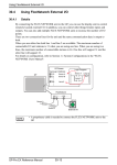
2.
Here, to assign the variable names
[Sensor] and [Fan] to external I/O, first,
click the [Data] menu’s [Configure I/O]
selection. The [Configure I/O] window will
then appear. Next, click the [Drivers] button
and the following [I/O Drivers] dialog box
will appear.
3.
Select the Flex Network Driver listed in the
GLC I/O list (left side), click the [Add]
button, and click the [Close] button. The
Configure I/O screen will then appear.
4.
Select the desired I/O unit and click the
[Setup] button.
(Default I/O unit setting is [FN-X16TS].)
- 39 -
5.
In the I/O Unit Setup screen’s [Model Code]
selection box, click on [FN-XY08TS] and
click on [OK]. Control then returns to the
Configure I/O screen.
6.
Under the FN-XY08TS, I0 through I7 and
Q0 through Q7 are displayed. The "I"
represents input, and the "Q" represents
the output signal’s external I/O.
Here, double-click "I3", type "Sensor" and
press [ENTER].
7.
When the following dialog box appears,
click the [OK] button.
Naming I3 creates a variable name for I3,
and allocates that variable to the FNXY08TS unit’s No. 3 input terminal.
NOTE: “Discrete” indicates a variable type
that uses bit units for processing.
- 40 -
8.
Next, use the same procedure to assign
the name "Fan" to "Q3". Variable names
allocated here are used by the logic
program and/or screen creation software to
access external devices.
Here, we will assign “sensor” to a NormallyOpen contact or a Normally-Closed contact
instruction that will receive input from an
external input terminal. Similarly, output to
the external output terminal can be created
by assigning “fan” to an OUT instruction.
3. Creating Internal Variables
Here, we will create named variables to be used for internal relays, registers,
timers, and counters.
1.
Let’s create the variable “Run”, which will
represent an internal relay.
First, in the Pro-Control Editor [Data] menu
click [Variable Type] to call up the [Variable
Type] dialog box.
2.
Enter “Run” in the “Name” field, and select
“Discrete” from the left-side Variable type
menu, which processes data in bit units.
Select "Internal" to specify that the variable
being created is an internal variable, and
click on [OK].
- 41 -
4. Creating Logic Programs
A logic program can be created by simply inserting instructions in a rung.
1.
Select [START] on Rung 1, and click the
Tool Bar’s
icon. Be sure to select
[START] when creating the first rung.
2.
Click the Tool Bar’s
icon and create a
Normally-Open contact on Rung 2. Next,
on the same rung, click
twice to create
two (2) Normally-Closed contacts. Last,
click
to create a Coil.
- 42 -
3.
In Pro-Control’s [Data] menu, click
[Variable List]. From the list of variables,
select "Run". Without releasing your mouse
button, drag and drop "Run" to the far left
side Normally-Open contact.
4.
To create an automatic hold circuit, drag
the "Run" circuit’s left-side connection line
to the right side to create an OR circuit.
(see figure)
5.
Click on the lower branch of the OR circuit
to select it. Then, click
to create a
Normally-open contact. (see figure)
- 43 -
6.
Next, we’ll assign variables from the I/O
Configuration to the logic program.
Select "Sensor" and drag it to the left-most
Normally-Closed contact. Repeat the
process twice with "Fan", by dragging it to
the OP circuit’s Normally-Open contact and
to the Coil.
7.
To insert a new rung below Rung 2, select
icon.
Rung 2 and click on the
- 44 -
8.
Click on the
icon to create a NormallyOpen contact on Rung 3. (see diagram)
9.
Click on the
icon to create an On-Delay
timer (TON) instruction. Enter the timer
name "Run_Time_Timer" and press
[Enter].
10.
When the variable confirmation dialog box
appears, click [OK].
The name (variable) assigned to the OnDelay timer will be designated as a “Timer”
type of variable. Use the same process to
assign variables to contacts and coils.
11.
Double-click the "0" that appears in the
lower left corner of the On-Delay timer to
call up the [Data Value] dialog box.
Enter "5000" (milliseconds) in the "Change
to" field to set the operating time to five
seconds, and click [OK].
- 45 -
12.
Drag the variable name "Fan" from Rung 2
and drop it onto the Normally-open contact
in Rung 3.
In the same way, drag "Run_Time_Timer,”
from Rung 3, and drop it on the second
Normally-closed contact in Rung 2.
(as shown)
13.
After "Run_Time_Timer" is dropped on
Rung 2, a pop-up variable window will
appear. Double-click on this window’s
[Run_Time_Timer. Q] variable, which
designates the output bit used for
"Run_Time_Timer.”
NOTE: The variable "Run_Time_Timer. Q"
is a dedicated variable, and is created
automatically when the Run Time Timer is
created in step 10. This bit information
(contact information) indicates that the time
set in the Run Time Timer has elapsed.
- 46 -
14.
Your logic program is now completed. Click
on the Tool Bar’s
icon to save the logic
program.
Important: This program’s variable
information is imported to GP-PRO/PB III
editor when the program is saved. Be sure
to save your logic program before using
the editor to create a GLC screen.
5. Creating GLC Screens
Here, we will create a GLC display screen. Do not quit Pro-Control Editor after
starting up GP-PRO/PBIII.
1.
After saving your logic program, click the
Project Manager’s [Screen] icon to call up
the Screen Editor. Next, click on the Tool
Bar’s
(New) icon to create a new
screen.
- 47 -
2.
Select “Base Screen” as the screen type
and click the [OK] button.
3.
Click on Pro-Control Editor to activate it
and drag "Run" (Rung 2 Normally-open
contact) to the GP-PRO/PBIII base screen.
Be sure to drag/select the entire command,
not just the variable, to the GP-PRO/PBIII
screen.
Important: You must save your logic
program before dragging and dropping
an instruction.
- 48 -
4.
Select "Bit Switch" for the Part to use, and
click [OK].
5.
In the [Bit Switch Settings] dialog box,
select "Momentary" in the "Function" area,
which turns a bit (switch) ON only while the
touch panel switch is touched.
Next, click [Place] and position the bit
switch on the base screen.
The switch’s label (text displayed on the
switch) and shape can also be set.
- 49 -
6.
Use the same procedure to drag the Ondelay Timer (Rung 2) to the base screen.
The On-delay timer is treated as a Keypad
Input Display when it is placed on a base
screen.
7.
In the [Keypad Input Display Setting] dialog
box, designate [Pop-up/ Exists].
Next, click [Place] and position the Keypad
Input Display on the base screen.
The Keypad Input Display, when touched,
displays a keypad on the GLC screen,
allowing you to input numerical values.
8.
Next, click the Tool Bar’s
icon to call up
the [Save As] dialog box. Enter "1" in the
“Screen” field and click the [OK] button.
Setting the screen number to "1" designates that the screen will be used as the
initial screen when the GLC is started.
- 50 -
6. Transferring Screens and Logic Programs/ Checking Operation
In this step, we will transfer the logic program and project screens we created to
the GLC to confirm that they operate correctly.
Prior to transferring GP-PRO/PBIII data, be sure to save your project (.prw) file.
1.
Quit both Pro-Control Editor and GP-PRO/
PBIII.
Next, click on the Project Manager’s
[Project] menu and select [Save As].
Enter a file name and click [Save].
2.
Click the Project Manager’s [Transfer] icon
and the following screen will appear.
- 51 -
3.
Click the Tool Bar’s
icon to call up the
[Transfer Settings] dialog box. In the "Send
Information" field, select "Control Data” and
click [OK].
Next, select the desired port in the
[Communication Port] field, and click on
[OK].
4.
Connect the data transfer cable to the
GLC, and click on the Tool Bar’s
icon.
(sends both the screen and control data to
the GLC).
5.
After data transfer is completed, the GLC is reset and the screen you created is
displayed.
Check that all screens and logic programs operate as expected.
The logic program created in this exercise should perform the following actions.
• The fan starts rotating when "Run" is touched, and halts after five seconds.
• Touching the Keypad Input Display on the touch panel allows you to adjust the
fan’s stop (OFF) time.
• If the sensor is activated while the fan is rotating, the fan is stopped.
This completes the basic procedure for developing an application. For a detailed
explanation of the features of GP-PRO/PB III and Pro-Control Editor, please refer
to each product’s manuals and help files.
- 52 -
© Copyright 2004 Digital Electronics Corporation. All rights reserved.
- 53 -