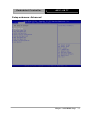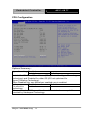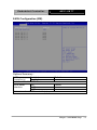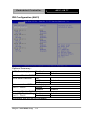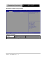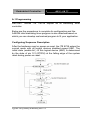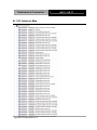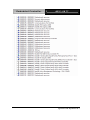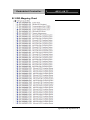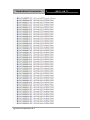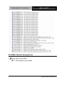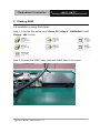
1
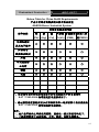
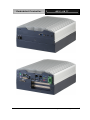
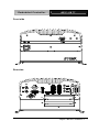
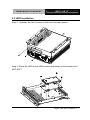
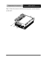
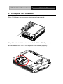
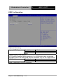
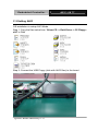
Embedded Controller AEC-6877 AEC-6877 Fanless Embedded Controller Intel® CoreTM i7/ i5 Celeron® Processor with 2 Gigabit Ethernet 2 COM, 4 USB3.0, 2 DisplayPort™ 2 PCI or 1 PCI-Express[x4] DVI-D, CFast™, SATA 3.0Gb/s AEC-6877 Manual 2nd Ed. August 2013 Embedded Controller AEC-6877 Copyright Notice This document is copyrighted, 2012. All rights are reserved. The original manufacturer reserves the right to make improvements to the products described in this manual at any time without notice. No part of this manual may be reproduced, copied, translated, or transmitted in any form or by any means without the prior written permission of the original manufacturer. Information provided in this manual is intended to be accurate and reliable. However, the original manufacturer assumes no responsibility for its use, or for any infringements upon the rights of third parties that may result from its use. The material in this document is for product information only and is subject to change without notice. While reasonable efforts have been made in the preparation of this document to assure its accuracy, AAEON assumes no liabilities resulting from errors or omissions in this document, or from the use of the information contained herein. AAEON reserves the right to make changes in the product design without notice to its users. i Embedded Controller AEC-6877 Acknowledgments Award is a trademark of Award Software International, Inc. CompactFlash™ is a trademark of the Compact Flash Association. Intel®, Celeron® and Core™ are trademarkes of Intel® Corporation. Microsoft Windows is a registered trademark of Microsoft Corp. PC/AT, PS/2, and VGA are trademarks of International Business Machines Corporation. ® All other product names or trademarks are properties of their respective owners. ii Embedded Controller AEC-6877 Packing List Before you begin operating your PC, please make sure that the following materials have been shipped: 1 AEC-6877 Embedded Controller 1 Phoenix Power Connector 4 M3 x 4mm Screws 6 6# -32 x 10mm Screws 2 Wallmount Brackets 1 DVD-ROM for manual (in PDF format) and Drivers If any of these items should be missing or damaged, please contact your distributor or sales representative immediately. iii Embedded Controller AEC-6877 Safety & Warranty 1. Read these safety instructions carefully. 2. Keep this user's manual for later reference. 3. Disconnect this equipment from any AC outlet before cleaning. Do not use liquid or spray detergents for cleaning. Use a damp cloth. 4. For pluggable equipment, the power outlet must be installed near the equipment and must be easily accessible. 5. Keep this equipment away from humidity. 6. Put this equipment on a firm surface during installation. Dropping it or letting it fall could cause damage. 7. The openings on the enclosure are for air convection. Protect the equipment from overheating. DO NOT COVER THE OPENINGS. 8. Make sure the voltage of the power source is correct before connecting the equipment to the power outlet. 9. Position the power cord so that people cannot step on it. Do not place anything over the power cord. 10. All cautions and warnings on the equipment should be noted. 11. If the equipment is not used for a long time, disconnect it from the power source to avoid damage by transient over-voltage. 12. Never pour any liquid into an opening. This could cause fire or electrical shock. 13. Never open the equipment. For safety reasons, only qualified service personnel should open the equipment. 14. If any of the following situations arises, get the equipment checked by service personnel: a. The power cord or plug is damaged. b. Liquid has penetrated into the equipment. c. The equipment has been exposed to moisture. iv Embedded Controller AEC-6877 d. The equipment does not work well, or you cannot get it to work according to the user’s manual. e. The equipment has been dropped and damaged. f. The equipment has obvious signs of breakage. 15. DO NOT LEAVE THIS EQUIPMENT IN AN ENVIRONMENT WHERE THE STORAGE TEMPERATURE IS BELOW -20°C (-4°F) OR ABOVE 70°C (158°F). IT MAY DAMAGE THE EQUIPMENT. FCC This device complies with Part 15 FCC Rules. Operation is subject to the following two conditions: (1) this device may not cause harmful interference, and (2) this device must accept any interference received including interference that may cause undesired operation. Caution: There is a danger of explosion if the battery is incorrectly replaced. Replace only with the same or equivalent type recommended by the manufacturer. Dispose of used batteries according to the manufacturer’s instructions and your local government’s recycling or disposal directives. v Embedded Controller AEC-6877 Below Table for China RoHS Requirements 产品中有毒有害物质或元素名称及含量 AAEON Boxer/ Industrial System 有毒有害物质或元素 部件名称 铅 汞 (Pb) (Hg) 印刷电路板 镉 六价铬 多溴联苯 多溴二苯 (Cd) (Cr(VI)) (PBB) 醚(PBDE) × ○ ○ ○ ○ ○ × ○ ○ ○ ○ ○ × ○ ○ ○ ○ ○ × ○ ○ ○ ○ ○ 硬盘 × ○ ○ ○ ○ ○ 电源 × ○ ○ ○ ○ ○ 及其电子组件 外部信号 连接器及线材 外壳 中央处理器 与内存 O:表示该有毒有害物质在该部件所有均质材料中的含量均在 SJ/T 11363-2006 标准规定的限量要求以下。 X:表示该有毒有害物质至少在该部件的某一均质材料中的含量超出 SJ/T 11363-2006 标准规定的限量要求。 备注: 一、此产品所标示之环保使用期限,系指在一般正常使用状况下。 二、上述部件物质中央处理器、内存、硬盘、电源为选购品。 vi Embedded Controller AEC-6877 Contents Chapter 1 General Information 1.1 Introduction................................................................ 1-2 1.2 Features .................................................................... 1-4 1.3 Specifications ............................................................ 1-5 Chapter 2 Hardware Installation 2.1 Dimension ................................................................. 2-2 2.2 COM1 ~ COM2 TX / RX LED (CN2) ......................... 2-4 2.3 RS-232 Box Header (COM 1) ................................... 2-4 2.4 USB Box Header (USB1 ~ USB3)............................. 2-4 2.5 HDD Installation ........................................................ 2-5 2.6 CFast™ Card Installation .......................................... 2-7 2.7 PCI-Express Card Installation ................................... 2-8 2.8 Wallmount Bracket Installation.................................. 2-9 Chapter 3 AMI BIOS Setup 3.1 System Test and Initialization. .................................. 3-2 3.2 AMI BIOS Setup ........................................................ 3-3 Chapter 4 Driver Installation 4.1 Installation ................................................................. 4-3 Appendix A Programming The Watchdog Timer A.1 Programming ........................................................A-2 A.2 ITE8728 Watchdog Timer Initial Program..............A-6 vii Embedded Controller AEC-6877 Appendix B I/O Information B.1 I/O Address Map ..................................................B-2 B.2 Memory Address Map ..........................................B-4 B.3 IRQ Mapping Chart ..............................................B-5 B.4 DMA Channel Assignments .................................B-7 Appendix C RAID & AHCI Settings C.1 Setting RAID ......................................................... C-2 C.2 Setting AHCI ....................................................... C-12 viii Embedded Controller AEC-6877 Chapter 1 General Information Chapter 1 General Information 1-1 Embedded Controller AEC-6877 1.1 Introduction Due to the growing popularity from the IPC market, the newest Boxer series AEC-6877 has been introduced by AAEON. The AEC-6877 is a fanless industrial grade embedded controller with superior thermal solution inside which is designed for harsh environment use. With newly Intel® high performance 3rd generation processor provides customers powerful computing technology and AEC-6877 adopts Intel® QM77 power chipset support three independent displays which is convenient for customer in their applications. Also with rich I/O ports with VGA, DVI, Display port, Ethernet, RS-232/422/485 and USB 3.0, it helps you shorten product development time to fulfill extensive needs in various projects. AEC-6877 is an ideal embedded platform for implementing custom applications for diversified applications. Stable Design for Rugged Environment The AEC-6877 is designed for rugged environments due to the following reasons; first, it can withstand tough vibration testing up to 5g rms. With the anti-vibration hard drive device option, the AEC-6877 can be used in high vibration environments. In addition, the AEC-6877 offers low power consumption system that while operating in ambient temperatures ranging from 0° to 55°C. Chapter 1 General Information 1-2 Embedded Controller AEC-6877 The AEC-6877 is a standalone high performance controller designed for long-life operation and with high reliability. It can replace traditional methods and become the mainstream controller for the multimedia entertainment market. Chapter 1 General Information 1-3 Embedded Controller AEC-6877 1.2 Features Fanless Design Intel® Core™ i7-3610QE/ i7-2710QE/ i5-2510E/ Celeron®-B810 Processor Intel® QM77 Chipset Gigabit Ethernet, RJ-45 x 2 Three Independent Video Output for 2 DisplayPort™ + VGA or DVI USB3.0 x 4 PCI-Express[x4] Slot x 1 or PCI x 2 COM x 2 Chapter 1 General Information 1-4 Embedded Controller AEC-6877 1.3 Specifications Intel® CoreTM i7-3610QE 2.3 GHz/ CPU i7-2710QE 2.1 GHz/ i5-2510E 2.5 GHz/ Celeron®-B810 1.6 GHz Processor with socket PGA988 Chipset Intel® QM77 System Memory 204-pin dual-channel DDR3 SODIMM 1066/1333/1600 MHz x 2, up to 16 GB Display Interface VGA DB-15 x 1 DVI DVI-D x 1, support 1920 x 1080 @ 60 Hz Storage Device Others DisplayPort™ x 2 SSD CFast™ slot HDD SATA 6.0Gb/s x 2 support RAID 0, 1, 5, 10 Network Front I/O LAN Gigabit Ethernet, RJ-45 x 2 Wireless Optional by Mini Card Serial Port RS-232 x 1 Others Push Power button x 1 Standard Antenna Hole x 2 Rear I/O USB Host USB3.0 x 4 LAN RJ-45 x 2 Serial Port RS-232/422/485 x 1 Audio Mic-in, Line-out, Line-out Chapter 1 General Information 1-5 Embedded Controller Expansion AEC-6877 KB/MS PS/2 Keyboard x 1 + Mouse x 1 Others Power input x 1 PCI-E PCI-E[x4] x 1 (AxM series) or PCI x 2 (BxM series) Indicator Front Power LED x 1, HDD active LED x 1 Power Requirement DC 9~30V with 3-pin terminal block System Cooling Passive cooling Mounting Wallmount Operating Temperature 32 oF ~ 122oF (0oC ~ 50oC)—with airflow Storage Temperature -4oF ~ 158oF (-20oC ~ 70oC) Storage Humidity 10%~95% @ 40oC, non-condensing Anti-Vibration 5 g rms/ 5~500 Hz/ operation-CFast™; 1 g rms/ 5~500 Hz/ operation-HDD Anti-Shock 20 G peak acceleration (11 msec. duration) – HDD Certification EMC Dimension (W x H x D) CE/FCC Class A 8.19” x 4.02” x 9.37” (208mm x 102mm x 238mm) Gross Weight 13.2 lb (6 Kg) OS Support Windows® XP Embedded, Windows® XP, Windows® 7, Linux Fedora 10 Chapter 1 General Information 1-6 Embedded Controller AEC-6877 Chapter 1 General Information 1-7 Embedded Controller AEC-6877 Chapter 2 Hardware Installation Chapter 2 Hardware Installation 2-1 Embedded Controller 2.1 Dimension Chapter 2 Hardware Installation 2 - 2 AEC-6877 Embedded Controller AEC-6877 Front side Rear side Chapter 2 Hardware Installation 2 - 3 Embedded Controller AEC-6877 2.2 COM1 ~ COM2 TX / RX LED (CN2) Pin Signal Pin Signal 1 +5V 2 GND 3 TX_LED_COM1 4 -TX_LED_COM1 5 RX_LED_COM1 6 -RX_LED_COM1 7 COM2_RS232_PWR 8 GND 9 TX_LED_COM2 10 -TX_LED_COM2 11 RX_LED_COM2 12 -RX_LED_COM2 13 COM2_RS485_PWR 14 COM2_RS422_PWR Note: The COM port cannot support baud rate at 115200 since the hardware limitation of the motherboard EMB-QM77. 2.3 RS-232 Box Header (COM 1) Pin Signal Pin Signal 1 DCD 2 RXD 3 TXD 4 DTR 5 GND 6 DSR 7 RTS 8 CTS 9 RI 10 N.C 2.4 USB Box Header (USB1 ~ USB3) Pin Signal Pin Signal 1 +5V 2 GND 3 USBD- 4 GND 5 USBD+ 6 USBD+ 7 GND 8 USBD- 9 GND 10 +5V Chapter 2 Hardware Installation 2 - 4 Embedded Controller AEC-6877 2.5 HDD Installation Step 1: Unfasten the four screws on the front and rear panels Step 2: Place the HDD to the HDD bracket and fasten to the bottom lid of AEC-6877 Chapter 2 Hardware Installation 2 - 5 Embedded Controller AEC-6877 Step 3: Fasten the screws on the front and rear panels, and the brackets of AEC-6877 Chapter 2 Hardware Installation 2 - 6 Embedded Controller AEC-6877 2.6 CFast™ Card Installation Step 1: Unfasten the screws on the front and rear panels Step 2: After installing the CFast™ Card to the CFast™ Slot, you have to use the cover to fix the CFast™ Card by fastening the two screws CFast™ Slot Chapter 2 Hardware Installation 2 - 7 Embedded Controller AEC-6877 2.7 PCI-Express Card Installation Step 1: Unfasten the screws on the front and rear panels Step 2: Install a hold-down bracket to fix the PCI or PCI-Express Card and make sure the PCI or PCI-Express Card installs properly Chapter 2 Hardware Installation 2 - 8 Embedded Controller AEC-6877 2.8 Wallmount Bracket Installation Fasten the brackets with the appropriate screws. Chapter 2 Hardware Installation 2 - 9 Embedded Controller AEC-6877 Chapter 3 AMI BIOS Setup Chapter 3 AMI BIOS Setup 3-1 Embedded Controller AEC-6877 3.1 System Test and Initialization These routines test and initialize board hardware. If the routines encounter an error during the tests, you will either hear a few short beeps or see an error message on the screen. There are two kinds of errors: fatal and non-fatal. The system can usually continue the boot up sequence with non-fatal errors. System configuration verification These routines check the current system configuration stored in the CMOS memory and BIOS NVRAM. If system configuration is not found or system configuration data error is detected, system will load optimized default and re-boot with this default system configuration automatically. There are four situations in which you will need to setup system configuration: 1. You are starting your system for the first time 2. You have changed the hardware attached to your system 3. The system configuration is reset by Clear-CMOS jumper 4. The CMOS memory has lost power and the configuration information has been erased. The AEC-6877 CMOS memory has an integral lithium battery backup for data retention. However, you will need to replace the complete unit when it finally runs down. Chapter 3 AMI BIOS Setup 3-2 Embedded Controller AEC-6877 3.2 AMI BIOS Setup AMI BIOS ROM has a built-in Setup program that allows users to modify the basic system configuration. This type of information is stored in battery-backed CMOS RAM and BIOS NVRAM so that it retains the Setup information when the power is turned off. Entering Setup Power on the computer and press <Del>or <F2> immediately. This will allow you to enter Setup. Main Set the date, use tab to switch between date elements. Advanced Advanced BIOS Features Setup including TPM, ACPI, etc. Chipset Host bridge parameters. Boot Enables/disable quiet boot option. Security Set setup administrator password. Save&Exit Exit system setup after saving the changes. Chapter 3 AMI BIOS Setup 3-3 Embedded Controller Setup Menu Setup submenu: Main Chapter 3 AMI BIOS Setup 3-4 AEC-6877 Embedded Controller AEC-6877 Setup submenu: Advanced Chapter 3 AMI BIOS Setup 3-5 Embedded Controller AEC-6877 ACPI Settings Options Summary : ACPI Sleep State Suspend Disabled S1 (CPU Stop Clock) S3 (Suspend to RAM) Default Select the ACPI sleep state the system will enter when the SUSPEND button is pressed. Chapter 3 AMI BIOS Setup 3-6 Embedded Controller AEC-6877 Trusted Computing Option Summary : TPM SUPPORT Disable Default Enable Enables or Disables BIOS support for security device. O.S. will not show Security Device. TCG EFI protocol and INT1A interface will not be available. Chapter 3 AMI BIOS Setup 3-7 Embedded Controller AEC-6877 CPU Configuration Options Summary : Hyper-threading Disabled Enabled Default Enabled for Windows XP and Linux (OS optimized for Hyper-Threading Technology) and Disabled for other OS (OS not optimized for Hyper-Threading Technology). When Disabled only one thread per enabled core is enabled. Intel Disabled Default Virtualization Enabled Technology When enabled, a VMM can utilize the additional hardware capabilities provided by Vanderpool Technology Chapter 3 AMI BIOS Setup 3-8 Embedded Controller AEC-6877 SATA Configuration (IDE) Options Summary : SATA Enabled Default Controller(s) Disabled Enable or disable SATA Device. SATA Mode IDE Default Selection AHCI RAID Determines how SATA controller(s) operate. Chapter 3 AMI BIOS Setup 3-9 Embedded Controller AEC-6877 IDE Configuration (AHCI) Options Summary : SATA Controller(s) Disabled Enabled Default Enable or Disable SATA Port. SATA Mode Selection IDE AHCI Selected RAID Determines how SATA controller(s) operate. Port 0 ~ Port 4 Disable Enabled Enabled Enable or Disable SATA Port Serial ATA Port Hot Plug Disable Default Port 0 ~ Port 4 Enabled Designates this port as Hot Pluggable. Chapter 3 AMI BIOS Setup 3-10 Embedded Controller AEC-6877 IDE Configuration (RAID) Options Summary : SATA Controller(s) Disabled Enabled Default Enable or Disable SATA Port. SATA Mode Selection IDE AHCI RAID Selected Determines how SATA controller(s) operate. Port 0 ~ Port 4 Disable Enabled Enabled Enable or Disable SATA Port Serial ATA Port Hot Plug Disable Default Port 0 ~ Port 4 Enabled Designates this port as Hot Pluggable. Chapter 3 AMI BIOS Setup 3-11 Embedded Controller Intel TXT(LT) Configuration Chapter 3 AMI BIOS Setup 3-12 AEC-6877 Embedded Controller AEC-6877 PCH-FW Configuration Options Summary : MDES BIOS Status Disabled Default Code Enabled Enable/Disable MDES BIOS Status Code. Firmware Update Configure Management Engine Technology Configuration Parameters Chapter 3 AMI BIOS Setup 3-13 Embedded Controller AEC-6877 Firmware Update Configuration Options Summary : Me FW Image Disabled Default Re-Flash Enabled Enable/Disable Me FW Image Re-Flash function. Chapter 3 AMI BIOS Setup 3-14 Embedded Controller AEC-6877 AMT Configuration Options Summary : Intel AMT Disabled Enabled Default Enable/Disable Intel ® Active Management Technology BIOS Extension. Note : iAMT H/W is always enabled. This option just controls the BIOS extension execution. If enabled, this requires additional firmware in the SPI device Un-Configure ME Disabled Default Enabled OEMFlag Bit 15: Un-Configure ME without password. Chapter 3 AMI BIOS Setup 3-15 Embedded Controller AEC-6877 USB Configuration Options Summary : Legacy USB Support Enabled Default Disabled Auto Enable Legacy USB support. AUTO option disables legacy support if no USB devices are connected. DISABLE option will keep USB devices available only for EFI applications. xHCI Mode Disabled Enabled Mode of operation of xHCI controller. Chapter 3 AMI BIOS Setup 3-16 Embedded Controller AEC-6877 Super IO Configuration Options Summary : Serial Port 0 Configuration Serial Port 1 Configuration Set Parameters of Serial Port 3 (COMA) Set Parameters of Serial Port 4 (COMB) Chapter 3 AMI BIOS Setup 3-17 Embedded Controller AEC-6877 Serial Port 0 Configuration Options Summary : Serial Port Disabled Enabled Default Enable or Disable Serial Port (COM) Change Settings Auto Default IO=3F8h; IRQ=3,4; IO=2F8h; IRQ=3,4; IO=3E8h; IRQ=3,4; IO=2E8h; IRQ=3,4;; Select an optimal setting for Super IO device. Chapter 3 AMI BIOS Setup 3-18 Embedded Controller AEC-6877 Serial Port 1 Configuration Options Summary : Serial Port Disabled Enabled Default Enable or Disable Serial Port (COM) Change Settings Auto Default IO=3F8h; IRQ=3,4; IO=2F8h; IRQ=3,4; IO=3E8h; IRQ=3,4; IO=2E8h; IRQ=3,4;; Select an optimal setting for Super IO device. Device Mode RS-232 Default RS-422 RS-485 Change the Serial Port mode. Select <RS-232> or <RS-422> or <RS-485> mode Chapter 3 AMI BIOS Setup 3-19 Embedded Controller H/W Monitor Chapter 3 AMI BIOS Setup 3-20 AEC-6877 Embedded Controller AEC-6877 Setup submenu: Chipset Chapter 3 AMI BIOS Setup 3-21 Embedded Controller AEC-6877 PCH-IO Configuration Options Summary : Power Mode ATX Type Default AT Type Select power supply mode. Restore AC Power Power off Loss Power on Last State Default Select AC power state when power is re-applied after a power failure. Notice: The system will power up after restore AC power if this item set to last state and shuts down via iAMT remote control. PCH LAN Controller Enabled Default Disabled Enable or disable onboard NIC. Wake on LAN Enabled Default Disabled Enable or disable integrated LAN to wake the system. (The Wake On LAN cannot be disabled if ME is on at Sx state. ) Chapter 3 AMI BIOS Setup 3-22 Embedded Controller AEC-6877 Deep S5 Disabled Default Enabled Enabled/Disabled Deep S5. Note : When Deep S5 is enabled, Intel ® AMT and Wake On PCH LAN functions are not available In system shut down. Mini PCIe Speed Gen1 Gen2 Default Select Mini PCI Express port speed. Chapter 3 AMI BIOS Setup 3-23 Embedded Controller AEC-6877 System Agent (SA) Configuration Options Summary : VT-d Disabled Enabled Default Check to enable VT-d function on MCH PEG0 – Gen X Auto Default Gen1 Gen2 Gen3 Configure PEG0 B0:D1:F0 Gen1-Gen3 Graphics Config Graphics Settings. Configuration Chapter 3 AMI BIOS Setup 3-24 Embedded Controller AEC-6877 Graphics Configuration Options Summary : Primary Display Auto Default IGfx PEG Select which of IGFX/PEG/PCI Graphics device should be Primary Display Or select SG for Switchable Gfx Internal Graphics Auto Default Disabled Enabled Keep IGD enabled based on the setup options. DVMT Pre-Allocated 0M 32M 64M Default 96M 128M 160M 192M Chapter 3 AMI BIOS Setup 3-25 Embedded Controller AEC-6877 224M 256M 288M 320M 352M 384M 416M 448M 480M 512M Select DVMT 5.0 Pre-Allocated (Fixed) Graphics Memory size used by the Internal Graphics Device. DVMT Total Gfx Men 128M 256M MAX Default Select DVMT5.0 Total Graphic Memory size used by the Internal Graphics Device. Chapter 3 AMI BIOS Setup 3-26 Embedded Controller AEC-6877 Display Control Options Summary : Boot Display Select VBIOS Default Default CRT DisplayPort 1 DVI DisplayPort 2 Select the Video Device during POST and DOS. This has no effect if external graphics present. Chapter 3 AMI BIOS Setup 3-27 Embedded Controller AEC-6877 Setup submenu: Boot Options Summary : Quiet Boot Disabled Enabled Default Enables or disables Quiet Boot option Launch I82579LM PXE Disabled Default OpROM Enabled Enable or Disable Legacy Boot Option for I82579LM. Launch RTL8111E Disabled Default PXE OpROM Enabled Enable or Disable Legacy Boot Option for RTL8111E Boot options #X Your storage/disk devices Sets the system boot order Chapter 3 AMI BIOS Setup 3-28 Embedded Controller AEC-6877 Hard Drives BBS Priorities Chapter 3 AMI BIOS Setup 3-29 Embedded Controller AEC-6877 Submenu: Security Change User/Supervisor Password You can install a Supervisor password, and if you install a supervisor password, you can then install a user password. A user password does not provide access to many of the features in the Setup utility. If you highlight these items and press Enter, a dialog box appears which lets you enter a password. You can enter no more than six letters or numbers. Press Enter after you have typed in the password. A second dialog box asks you to retype the password for confirmation. Press Enter after you have retyped it correctly. The password is required at boot time, or when the user enters the Setup utility. Removing the Password Highlight this item and type in the current password. box press Enter to disable password protection. Chapter 3 AMI BIOS Setup 3-30 At the next dialog Embedded Controller AEC-6877 Setup submenu: Exit Chapter 3 AMI BIOS Setup 3-31 Embedded Controller AEC-6877 Chapter 4 Driver Installation 0B . Chapter 4 Driver Installation 4 -1 Embedded Controller AEC-6877 The AEC-6877 comes with an AutoRun DVD-ROM that contains all drivers and utilities that can help you to install the driver automatically. Insert the driver DVD, the driver DVD-title will auto start and show the installation guide. If not, please follow the sequence below to install the drivers. Follow the sequence below to install the drivers: Step 1 – Install Chipset Driver Step 2 – Install VGA Driver Step 3 – Install LAN Driver Step 4 – Install Audio Driver Step 5 – Install USB3.0 Driver Step 6 – Install RAID & AHCI Driver Step 7 – Install ME Driver Step 8 – Install Serial Port Driver (Optional) Please read instructions below for further detailed installations. Chapter 4 Driver Installation 4 -2 Embedded Controller 4.1 AEC-6877 Installation: Insert the AEC-6877 DVD-ROM into the DVD-ROM drive. And install the drivers from Step 1 to Step 8 in order. Step 1 – Install Chipset Driver 1. Click on the Step 1 - Chipset folder and double click on the infinst_autol_9.3.0.1026.exe file 2. Follow the instructions that the window shows 3. The system will help you install the driver automatically Step 2 – Install VGA Driver 1. Click on the Step 2 - VGA folder and select the OS folder your system is 2. Double click on the Setup.exe file located in each OS folder 3. Follow the instructions that the window shows 4. The system will help you install the driver automatically ® Note: If the OS is Windows XP, you have to install the driver of dotNet Framework first. Simply click on dotnetfx35.exe located in dotNet Framwork folder. Step 3 –Install LAN Driver 1. Click on the Step 3 - LAN folder and select the folder of LAN chip the system adopted 2. Select the OS folder your system is and double click on the .exe file located in each OS folder Chapter 4 Driver Installation 4 -3 Embedded Controller AEC-6877 3. Follow the instructions that the window shows 4. The system will help you install the driver automatically Step 4 –Install Audio Driver 1. Click on the Step 4 - Audio folder and select the OS folder your system is 2. Double click on the .exe located in each OS folder 3. Follow the instructions that the window shows 4. The system will help you install the driver automatically Step 5 – Install USB3.0 Driver 1. Click on the Step 5 - USB3.0 folder and double click on the Setup.exe file 2. Follow the instructions that the window shows 3. The system will help you install the driver automatically Step 6 – Install RAID & AHCI Driver Please refer to the Appendix C RAID & AHCI Settings Step 7 – Install ME Driver 1. Click on the Step 7 - ME folder and select the OS folder your system is 2. Double click on the .exe located in each OS folder 3. Follow the instructions that the window shows 4. The system will help you install the driver automatically Chapter 4 Driver Installation 4 -4 Embedded Controller AEC-6877 Step 8 – Serial Port Driver (Optional) 1. Click on the Step 8 - Serial Port Driver (Optional) and select the OS folder your system is 2. Double click on patch.bat file located in each OS folder 3. Follow the instructions that the window shows 4. The system will help you install the driver automatically Chapter 4 Driver Installation 4 -5 Embedded Controller Chapter 4 Driver Installation 4 -6 AEC-6877 Embedded Controller AEC-6877 Chapter 4 Driver Installation 4 -7 Embedded Controller AEC-6877 Appendix A Programming the Watchdog Timer Appendix A Programming the Watchdog Timer A-1 Embedded Controller AEC-6877 A.1 Programming AEC-6877 utilizes ITE IT8728 chipset as its watchdog timer controller. Below are the procedures to complete its configuration and the AAEON intial watchdog timer program is also attached based on which you can develop customized program to fit your application. Configuring Sequence Description After the hardware reset or power-on reset, the ITE 8728 enters the normal mode with all logical devices disabled except KBC. The initial state (enable bit ) of this logical device (KBC) is determined by the state of pin 121 (DTR1#) at the falling edge of the system reset during power-on reset. Appendix A Programming the Watchdog Timer A-2 Embedded Controller AEC-6877 There are three steps to complete the configuration setup: (1) Enter the MB PnP Mode; (2) Modify the data of configuration registers; (3) Exit the MB PnP Mode. Undesired result may occur if the MB PnP Mode is not exited normally. (1) Enter the MB PnP Mode To enter the MB PnP Mode, four special I/O write operations are to be performed during Wait for Key state. To ensure the initial state of the key-check logic, it is necessary to perform four write operations to the Special Address port (2EH). Two different enter keys are provided to select configuration ports (2Eh/2Fh) of the next step. (2) Modify the Data of the Registers All configuration registers can be accessed after entering the MB PnP Mode. Before accessing a selected register, the content of Index 07h must be changed to the LDN to which the register belongs, except some Global registers. (3) Exit the MB PnP Mode Set bit 1 of the configure control register (Index=02h) to 1 to exit the MB PnP Mode. Appendix A Programming the Watchdog Timer A-3 Embedded Controller AEC-6877 WatchDog Timer Configuration Registers Configure Control (Index=02h) This register is write only. Its values are not sticky; that is to say, a hardware reset will automatically clear the bits, and does not require the software to clear them. Appendix A Programming the Watchdog Timer A-4 Embedded Controller AEC-6877 WatchDog Timer Control Register (Index=71h, Default=00h) WatchDog Timer Configuration Register (Index=72h, Default=00h) WatchDog Timer Time-out Value Register (Index=73h, Default=00h) Appendix A Programming the Watchdog Timer A-5 Embedded Controller AEC-6877 A.2 ITE8728 Watchdog Timer Initial Program .MODEL SMALL .CODE Main: CALL Enter_Configuration_mode CALL Check_Chip mov cl, 7 call Set_Logic_Device ;time setting mov cl, 10 ; 10 Sec dec al Watch_Dog_Setting: ;Timer setting mov al, cl mov cl, 73h call Superio_Set_Reg ;Clear by keyboard or mouse interrupt mov al, 0f0h mov cl, 71h call Superio_Set_Reg ;unit is second. mov al, 0C0H mov cl, 72h call Superio_Set_Reg Appendix A Programming the Watchdog Timer A-6 Embedded Controller AEC-6877 ; game port enable mov cl, 9 call Set_Logic_Device Initial_OK: CALL Exit_Configuration_mode MOV AH,4Ch INT 21h Enter_Configuration_Mode PROC NEAR MOV SI,WORD PTR CS:[Offset Cfg_Port] MOV DX,02Eh MOV CX,04h Init_1: MOV AL,BYTE PTR CS:[SI] OUT DX,AL INC SI LOOP Init_1 RET Enter_Configuration_Mode ENDP Exit_Configuration_Mode PROC NEAR MOV AX,0202h CALL Write_Configuration_Data Appendix A Programming the Watchdog Timer A-7 Embedded Controller AEC-6877 RET Exit_Configuration_Mode ENDP Check_Chip PROC NEAR MOV AL,20h CALL Read_Configuration_Data CMP AL,87h JNE Not_Initial MOV AL,21h CALL Read_Configuration_Data CMP AL,12h JNE Not_Initial Need_Initial: STC RET Not_Initial: CLC RET Check_Chip ENDP Read_Configuration_Data PROC NEAR MOV DX,WORD PTR CS:[Cfg_Port+04h] OUT DX,AL Appendix A Programming the Watchdog Timer A-8 Embedded Controller AEC-6877 MOV DX,WORD PTR CS:[Cfg_Port+06h] IN AL,DX RET Read_Configuration_Data ENDP Write_Configuration_Data PROC NEAR MOV DX,WORD PTR CS:[Cfg_Port+04h] OUT DX,AL XCHG AL,AH MOV DX,WORD PTR CS:[Cfg_Port+06h] OUT DX,AL RET Write_Configuration_Data ENDP Superio_Set_Reg proc near push ax MOV DX,WORD PTR CS:[Cfg_Port+04h] mov al,cl out dx,al pop ax inc dx out dx,al ret Superio_Set_Reg endp.Set_Logic_Device proc near Set_Logic_Device proc near Appendix A Programming the Watchdog Timer A-9 Embedded Controller AEC-6877 push ax push cx xchg al,cl mov cl,07h call Superio_Set_Reg pop cx pop ax ret Set_Logic_Device endp ;Select 02Eh->Index Port, 02Fh->Data Port Cfg_Port DB 087h,001h,055h,055h DW 02Eh,02Fh END Main Note: Interrupt level mapping 0Fh-Dh: not valid 0Ch: IRQ12 . . 03h: IRQ3 02h: not valid 01h: IRQ1 00h: no interrupt selected Appendix A Programming the Watchdog Timer A-10 Embedded Controller AEC-6877 Appendix B I/O Information Appendix B I/O Information B-1 Embedded Controller B.1 I/O Address Map Appendix B I/O Information B-2 AEC-6877 Embedded Controller AEC-6877 Appendix B I/O Information B-3 Embedded Controller B.2 Memory Address Map Appendix B I/O Information B-4 AEC-6877 Embedded Controller AEC-6877 B.3 IRQ Mapping Chart Appendix B I/O Information B-5 Embedded Controller Appendix B I/O Information B-6 AEC-6877 Embedded Controller AEC-6877 B.4 DMA Channel Assignments Appendix B I/O Information B-7 Embedded Controller AEC-6877 Appendix C RAID & AHCI Settings Appendix C RAID & AHCI Settings C-1 Embedded Controller AEC-6877 C.1 Setting RAID OS installation to setup RAID Mode Step 1: Copy the files below from “Driver CD ->Step 6 - RAID&AHCI -> F6 Floppy - x86” to Disk Step 2: Connect the USB Floppy (disk with RAID files) to the board Appendix C RAID & AHCI Settings C-2 Embedded Controller AEC-6877 Step 3: The setting procedures “ In BIOS Setup Menu” A: Advanced -> SATA Configuration -> SATA Mode -> RAID Mode Step 4: The setting procedures “In BIOS Setup Menu” B: Advanced -> Launch Storage OpROM -> Enabled Appendix C RAID & AHCI Settings C-3 Embedded Controller AEC-6877 Step 5: The setting procedures “In BIOS Setup Menu” C: Boot -> Boot Option #1 -> DVD-ROM Type Step 6: The setting procedures “In BIOS Setup Menu” D: Save & Exit -> Save Changes and Exit Appendix C RAID & AHCI Settings C-4 Embedded Controller AEC-6877 Step 7: Press Ctrl-I to enter MAIN MENU Step 8: Choose “1.Create RAID Volume” Appendix C RAID & AHCI Settings C-5 Embedded Controller Step 9: RAID Level -> RAID0(Stripe) Step 10: Choose “Create Volume” Appendix C RAID & AHCI Settings C-6 AEC-6877 Embedded Controller AEC-6877 Step 11: Choose “Y” Step 12: Choose “5. Exit” Appendix C RAID & AHCI Settings C-7 Embedded Controller Step 13: Choose “Y” Step 14: Setup OS Appendix C RAID & AHCI Settings C-8 AEC-6877 Embedded Controller AEC-6877 Step 15: Press “F6” Step 16: Choose “S” Appendix C RAID & AHCI Settings C-9 Embedded Controller AEC-6877 Step 17: Choose “Intel(R) Mobile Express Chipset SATA RAID Controller” Step 18: It will show the model number you select and then press “ENTER” Appendix C RAID & AHCI Settings C-10 Embedded Controller AEC-6877 Step 19: Setup is starting Windows Appendix C RAID & AHCI Settings C-11 Embedded Controller AEC-6877 C.2 Setting AHCI OS installation to setup AHCI Mode Step 1: Copy the files below from “Driver CD -> Raid Driver -> F6 Floppy x86” to Disk Step 2: Connect the USB Floppy (disk with AHCI files) to the board Appendix C RAID & AHCI Settings C-12 Embedded Controller AEC-6877 Step 3: The setting procedures “ In BIOS Setup Menu” A: Advanced -> SATA Configuration -> SATA Configuration -> SATA Mode -> AHCI Mode Step 4: The setting procedures “In BIOS Setup Menu” B: Boot -> Boot Option #1 -> DVD-ROM Type Appendix C RAID & AHCI Settings C-13 Embedded Controller AEC-6877 Step 5: The setting procedures “In BIOS Setup Menu” C: Save & Exit -> Save Changes and Exit Step 6: Setup OS Appendix C RAID & AHCI Settings C-14 Embedded Controller AEC-6877 Step 7: Press “F6” Step 8: Choose “S” Appendix C RAID & AHCI Settings C-15 Embedded Controller AEC-6877 Step 9: Choose “Intel(R) 7 Series Chipset Family SATA AHCI Controller” Step 10: It will show the model number you select and then press “ENTER” Appendix C RAID & AHCI Settings C-16 Embedded Controller AEC-6877 Step 11: Setup is loading files Appendix C RAID & AHCI Settings C-17