1
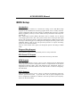
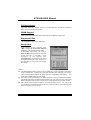
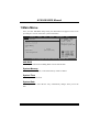
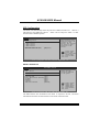
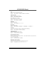
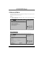
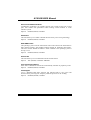
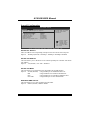
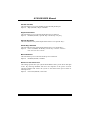
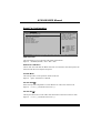
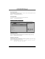
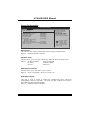
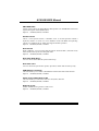
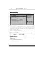
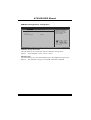
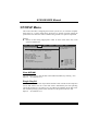
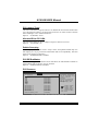
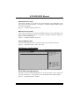
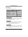
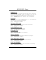
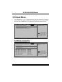
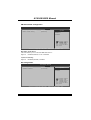
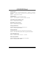
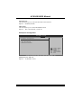
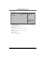
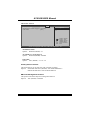
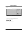
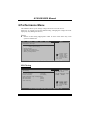
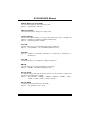
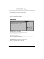
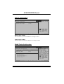
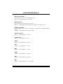
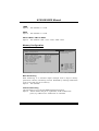
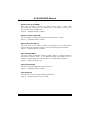
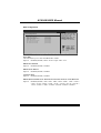
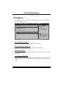
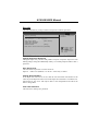
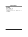
A780L3B BIOS Manual
BIOS Setup ................................................................................................ 1
1 Main Menu ............................................................................................. 3
2 Advanced Menu...................................................................................... 6
3 PCIPnP Menu....................................................................................... 16
4 Boot Menu............................................................................................. 19
5 Chipset Menu ....................................................................................... 21
6 Performance Menu .............................................................................. 29
7 Exit Menu ............................................................................................. 37
i
A780L3B BIOS Manual
BIOS Setup
Introduction
The purpose of this manual is to describe the settings in the AMI BIOS Setup
program on this motherboard. The Setup program allows users to modify the basic
system configuration and save these settings to CMOS RAM. The power of CMOS
RAM is supplied by a battery so that it retains the Setup information when the power
is turned off.
Basic Input-Output System (BIOS) determines what a computer can do without
accessing programs from a disk. This system controls most of the input and output
devices such as keyboard, mouse, serial ports and disk drives. BIOS activates at the
first stage of the booting process, loading and executing the operating system. Some
additional features, such as virus and password protection or chipset fine-tuning
options are also included in BIOS.
The rest of this manual will to guide you through the options and settings in BIOS
Setup.
Plug and Play Support
This AMI BIOS supports the Plug and Play Version 1.0A specification.
EPA Green PC Support
This AMI BIOS supports Version 1.03 of the EPA Green PC specification.
APM Support
This AMI BIOS supports Version 1.1&1.2 of the Advanced Power Management
(APM) specification. Power management features are implemented via the System
Management Interrupt (SMI). Sleep and Suspend power management modes are
supported. Power to the hard disk drives and video monitors can also be managed by
this AMI BIOS.
ACPI Support
AMI ACPI BIOS support Version 1.0/2.0 of Advanced Configuration and Power
interface specification (ACPI). It provides ASL code for power management and
device configuration capabilities as defined in the ACPI specification, developed by
Microsoft, Intel and Toshiba.
1
A780L3B BIOS Manual
PCI Bus Support
This AMI BIOS also supports Version 2.3 of the Intel PCI (Peripheral Component
Interconnect) local bus specification.
DRAM Support
DDR3 SDRAM (Double Data Rate III Synchronous DRAM) is supported.
Supported CPUs
This AMI BIOS supports the AMD CPU.
Using Setup
When starting up the computer, press
<Del> during the Power-On Self-Test
(POST) to enter the BIOS setup utility.
In the BIOS setup utility, you will see
General Help description at the top right
corner, and this is providing a brief
description of the selected item.
Navigation Keys for that particular menu
are at the bottom right corner, and you can
use these keys to select item and change
the settings.
Notice
z
z
z
General Help
Navigation Keys
The default BIOS settings apply for most conditions to ensure optimum performance
of the motherboard. If the system becomes unstable after changing any settings,
please load the default settings to ensure system’s compatibility and stability. Use
Load Setup Default under the Exit Menu.
For better system performance, the BIOS firmware is being continuously updated.
The BIOS information described in this manual is for your reference only. The actual
BIOS information and settings on board may be slightly different from this manual.
The content of this manual is subject to be changed without notice. We will not be
responsible for any mistakes found in this user’s manual and any system damage that
may be caused by wrong-settings.
2
A780L3B BIOS Manual
1 Main Menu
Once you enter AMI BIOS Setup Utility, the Main Menu will appear on the screen
providing an overview of the basic system information.
Main
Advanced
PCIPnP
BIOS SETUP UTILITY
Boot
Chipset
Performance
Use [ENTER], [TAB]
or [SHIFT-TAB] to
select a field.
System Overview
AMI BIOS
Version
:01.01.01
Build Date:01/01/11
Use [+] or [-] to
configure system Time.
System Memory
Size
:
System Time
System Date
Exit
[00 :00:00]
[Sat 01/01/2011]
> IDE Configuration
+Tab
F1
F10
ESC
Select Screen
Select Item
Change Field
Select Field
General Help
Save and Exit
Exit
vxx.xx (C)Copyright 1985-200x, American Megatrends, Inc.
AMI BIOS
Shows system information including BIOS version and built date.
System Memory
Shows system memory size, VGA shard memory will be excluded..
System Time
Set the system internal clock.
System Date
Set the system date. Note that the ‘Day’ automatically changes when you set the
date.
3
A780L3B BIOS Manual
IDE Configuration
The BIOS will automatically detect the presence of IDE/SATA devices. There is a
sub-menu for each IDE/SATA device. Select a device and press <Enter> to enter
the sub-menu of detailed options.
BIOS SETUP UTILITY
Main
IDE Confuguration
>
>
>
>
SATA
SATA
SATA
SATA
1
2
3
4
Device
Device
Device
Device
Hard Disk Write Protect
IDE Detect Time Out (Sec)
[Disabled]
[35]
While entering setup,
BIOS auto detects the
presence of IDE
devices. This displays
the status of auto
detection of IDE
devices.
Select Screen
Select Item
EnterGo to Sub Screen
F1
General Help
F10 Save and Exit
ESC Exit
vxx.xx (C)Copyright 1985-200x, American Megatrends, Inc.
SATA 1/2/3/4 Device
BIOS SETUP UTILITY
Main
SATA 1 Device
Device
Select the type
of device connected
to the system.
:
Type
[Auto]
LBA/Large Mode
[Auto]
Block (Multi-Sector Transfer)[Auto]
PIO Mode
[Auto]
DMA Mode
[Auto]
S.M.A.R.T
[Auto]
32Bit Data Transfer
[Enabled]
+F1
F10
ESC
Select Screen
Select Item
Change Option
General Help
Save and Exit
Exit
vxx.xx (C)Copyright 1985-200x, American Megatrends, Inc.
The BIOS detects the information and values of respective devices, and these
information and values are shown below to the name of the sub-menu.
4
A780L3B BIOS Manual
Type
Select the type of the IDE/SATA drive.
Options: Auto (Default) / CDROM / ARMD / Not Installed
LBA/Large Mode
Enable or disable the LBA mode.
Options: Auto (Default) / Disabled
Block (Multi-Sector Transfer)
Enable or disable multi-sector transfer.
Options: Auto (Default) / Disabled
PIO Mode
Select the PIO mode.
Options: Auto (Default) / 0 / 1 / 2 / 3 / 4
DMA Mode
Select the DMA mode.
Options: Auto (Default) / SWDMA0 ~ 2 / MWDMA0 ~ 2 / UDMA0 ~ 5
S.M.A.R.T
Set the Smart Monitoring, Analysis, and Reporting Technology.
Options: Auto (Default) / Disabled / Enabled
32Bit Data Transfer
Enable or disable 32-bit data transfer.
Options: Enabled (Default) / Disabled
Hard Disk Write Protect
Disable or enable device write protection.
is accessed through BIOS.
Options: Disabled (Default) / Enabled
This will be effective only if the device
IDE Detect Time Out (Sec)
Select the time out value for detecting IDE/SATA devices.
Options: 35 (Default) / 30 / 25 / 20 / 15 / 10 / 5 / 0
5
A780L3B BIOS Manual
2 Advanced Menu
The Advanced Menu allows you to configure the settings of CPU, Super I/O, Power
Management, and other system devices.
Notice
z
Beware of that setting inappropriate values in items of this menu may cause
system to malfunction.
Main
Advanced
PCIPnP
BIOS SETUP UTILITY
Boot
Chipset
Performance
Advanced Settings
Exit
Configure CPU.
WARNING: Setting wrong values in below sections
may cause system to malfunction.
>
>
>
>
>
>
CPU Configuration
SuperIO Configuration
Smart Fan Configuration
Hardware Health Configuration
Power Configuration
USB Configuration
Select Screen
Select Item
Enter Go to Sub Screen
F1
General Help
F10 Save and Exit
ESC Exit
vxx.xx (C)Copyright 1985-200x, American Megatrends, Inc.
CPU Configuration
This item shows the CPU information that the BIOS automatically detects.
Advanced
BIOS SETUP UTILITY
CPU Configuration
Module Version:
AGESA Version:
Physical Count:
Logical Count:
Enable/Disable
Secure Virtual Machine
Mode (SVM)
AMD CPU
Revision:
Cache L1:
Cache L2:
Cache L3:
Speed
:
NB Clk:
ncHT Speed :
WidthI/O :
Able to Change Freq
:
uCode Patch Level
:
Secure Virtual Machine Mode [Enabled]
PowerNow
[Enabled]
ACPI SRAT Table
[Enabled]
Probe Filter
[Auto]
+F1
F10
ESC
Select Screen
Select Item
Change Option
General Help
Save and Exit
Exit
vxx.xx (C)Copyright 1985-200x, American Megatrends, Inc.
6
A780L3B BIOS Manual
Secure Virtual Machine Mode
Virtualization Technology can virtually separate your system resource into several
parts, thus enhance the performance when running virtual machines or multi
interface systems.
Options: Enabled (Default) / Disabled
PowerNow
This item allows you to enable or disable the PowerNow power saving technology.
Options: Enabled (Default) / Disabled
ACPI SRAT Table
The operating system scans the ACPI SRAT at boot time and uses the information to
better allocate memory and schedule software threads for maximum performance.
This item controls whether the SRAT is made available to the operating system at
boot up, or not.
Options: Enabled (Default) / Disabled
Probe Filter
This item allows you to set initialization mode for Probe Filter.
Options: Auto (Default) / Disabled / MP Mode
Core Performance Boost
If this item is enabled, Revision E CPU automatically transition to pop-down p-state
Options: Enabled (Default) / Disabled
C1E Support
C1E is “Enhanced Halt State” function, this function helps to save power and
decrease heat by lowering CPU frequency while the processor is not working.
Options: Disabled (Default) / Enabled
7
A780L3B BIOS Manual
SuperIO Configuration
Advanced
BIOS SETUP UTILITY
Configure ITE8728 Super IO Chipset
Serial Port1 Address
Parallel Port Address
Parallel Port Mode
Parallel Port IRQ
OnBoard CIR Port
Keyboard PowerOn
Mouse PowerOn
Restore on AC Power Loss
[3F8/IRQ4]
[378]
[Normal]
[IRQ7]
[Disabled]
[Disabled]
[Disabled]
[Power Off]
Allows BIOS to Select
Serial Port1 Base
Addresses.
+F1
F10
ESC
Select Screen
Select Item
Change Option
General Help
Save and Exit
Exit
vxx.xx (C)Copyright 1985-200x, American Megatrends, Inc.
Serial Port1 Address
Select an address and corresponding interrupt for the first and second serial ports.
Options: 3F8/IRQ4 (Default) / 2F8/IRQ3 / 3E8/IRQ4 / 2E8/IRQ3 /Disabled
Parallel Port Address
This item allows you to determine access onboard parallel port controller with which
I/O Address.
Options: 378 (Default) / 278 / 3BC / Disabled
Parallel Port Mode
This item allows you to determine how the parallel port should function.
Options: Normal (Default) Using Parallel port as Standard Printer Port.
EPP
Using Parallel Port as Enhanced Parallel Port.
ECP
Using Parallel port as Extended Capabilities Port.
ECP+EPP
Using Parallel port as ECP & EPP mode.
ECP Mode DMA Channel
This item allows you to select parallel port ECP DMA.
Options: DMA3 (Default) / DMA0 / DMA1
8
A780L3B BIOS Manual
Parallel Port IRQ
This item allows you to select the IRQ for the onboard parallel port.
Options: IRQ7 (Default) / IRQ5 / Disabled
Keyboard PowerOn
This item allows you to control the keyboard power on function.
Options: Disabled (Default) / Specific Key / Stroke Key / Any Key
Specific Key Enter
This item will show only when Keyboard PowerOn is set “Specific Key.”
Stroke Keys Selected
This item will show only when Keyboard PowerOn is set “Stroke Key.”
Options: Ctrl+F1 (Default) / Wake Key / Power Key / Ctrl+F2 / Ctrl+F3 /
Ctrl +F4 / Ctrl+F5 / Ctrl+F6
Mouse PowerOn
This item allows you to control the mouse power on function.
Options: Disabled (Default) / Enabled
Restore on AC Power Loss
This setting specifies how your system should behave after a power fail or interrupts
occurs. By choosing Disabled will leave the computer in the power off state.
Choosing Enabled will restore the system to the status before power failure or
interrupt occurs.
Options: Power Off (Default) / Last State
9
A780L3B BIOS Manual
Smart Fan Configuration
Advanced
BIOS SETUP UTILITY
Smart Fan Configuration
CPU Smart Fan
Smart Fan Calibration
Control Mode
Fan Ctrl OFF(oC)
Fan Ctrl On( oC)
Fan Ctrl Start value
Fan Ctrl Sensitive
[Disabled]
When you choice [Auto]
,[3Pin] or [4Pin],
please run the
calibration to define
the Fan parameters for
Smart Fan control
+F1
F10
ESC
Select Screen
Select Item
Change Option
General Help
Save and Exit
Exit
vxx.xx (C)Copyright 1985-200x, American Megatrends, Inc.
CPU Smart Fan
This item allows you to control the CPU Smart Fan function.
Options: Disabled (Default) / Auto / 4Pin / 3Pin
Smart Fan Calibration
Choose this item and then the BIOS will auto test and detect the CPU/System fan
functions and show CPU/System fan speed.
Control Mode
This item provides several operation modes of the fan.
Options: Quiet / Performance / Manual
Fan Ctrl OFF(℃)
If the CPU/System Temperature is lower than the set value, FAN will turn off.
Options: 0~127 (℃) (With the interval of 1℃)
Fan Ctrl On(℃)
CPU/System fan starts to work under smart fan function when arrive this set value.
Options: 0~127 (℃) (With the interval of 1℃)
10
A780L3B BIOS Manual
Fan Ctrl Start Value
When CPU/System temperature arrives to the set value, the CPU/System fan will
work under Smart Fan Function mode.
Options: 0~127 (With the interval of 1)
Fan Ctrl Sensitive
Increasing the value will raise the speed of CPU/System fan.
Options: 1~127 (With the interval of 1)
Hardware Health Configuration
This item shows the system temperature, fan speed, and voltage information.
Advanced
BIOS SETUP UTILITY
Hardware Health Configuration
H/W Health Function
Shutdown Temperature
[Enabled]
[Disabled]
Enables Hardware
Health Monitoring
Device.
CPU Temperature
SYS Temperature
CPU Fan
Sytem1 Fan
CPU Voltage
DDR Voltage
+12.0V
+5.00V
Chip Voltage
+F1
F10
ESC
Select Screen
Select Item
Change Option
General Help
Save and Exit
Exit
vxx.xx (C)Copyright 1985-200x, American Megatrends, Inc.
H/W Health Function
If with a monitoring system, the system will show PC health status during POST stage.
Options: Enabled (Default) / Disabled
Shutdown Temperature
This item allows you to set up the CPU shutdown Temperature. This item is only
effective under Windows 98 ACPI mode.
Options: Disabled (Default) / 60℃/140℉ / 65℃/149℉ / 70℃/158℉ / 75℃/167℉
/ 80℃/176℉ / 85℃/185℉ / 90℃/194℉
11
A780L3B BIOS Manual
Power Configuration
Advanced
BIOS SETUP UTILITY
ACPI Settings
EuP Control
Suspend mode
ACPI Version Features
ACPI APIC support
AMI OEMB table
Headless mode
[Disabled]
[S1 (POS)]
[ACPI v1.0]
[Enabled]
[Enabled]
[Disabled]
RTC Resume
[Disabled]
RTC Alarm Date(Days)
RTC Alarm Time
USB Wakeup From S3/S4
[Disabled]
Power On by PCIE/Onboard LAN [Disabled]
Wake Up by PCI
[Disabled]
When EuP Enabled,
System meets EuP
requirement.
All wake up events
do not work except
Power Button after
power down system(S5).
+F1
F10
ESC
Select Screen
Select Item
Change Option
General Help
Save and Exit
Exit
vxx.xx (C)Copyright 1985-200x, American Megatrends, Inc.
EuP Control
This item is used to enable or disable EuP Control (Energy Using Products).
Options: Disabled (Default) / Enabled
Suspend mode
The item allows you to select the suspend type under the ACPI operating system.
Options: S1 (POS) (Default)
Power on Suspend
S3 (STR)
Suspend to RAM
S1 & S3
POS+STR
ACPI Version Features
The item allows you to select the version of ACPI.
Options: ACPI v1.0 (Default) / ACPI v2.0 / ACPI v3.0
ACPI APIC support
This item is used to enable or disable the motherboard's APIC (Advanced
Programmable Interrupt Controller). The APIC provides multiprocessor support,
more IRQs and faster interrupt handling.
Options: Enabled (Default) / Disabled
12
A780L3B BIOS Manual
AMI OEMB table
Set this value to allow the ACPI BIOS to add a pointer to an OEMB table in the Root
System Description Table (RSDT) table.
Options: Enabled (Default) / Disabled
Headless mode
This is a server-specific feature. A headless server is one that operates without a
keyboard, monitor or mouse. To run in headless mode, both BIOS and operating
system (e.g. Windows Server 2003) must support headless operation.
Options: Disabled (Default) / Enabled
RTC Resume
When “Enabled”, you can set the date and time at which the RTC (real-time clock)
alarm awakens the system from Suspend mode.
Options: Disabled (Default) / Enabled
RTC Alarm Date (Days)
You can choose which date the system will boot up.
RTC Alarm Time
You can choose the system boot up time, input hour, minute and second to specify.
USB Wakeup from S3/S4
This item allows you to enable or disabled the USB resume from S3/S4 function.
Options: Disabled (Default) / Enabled
Power On by PCIE/Onboard LAN
This item allows you control the wake on LAN (WOL) function.
Options: Disabled (Default) / Enabled
Wake Up by PCI
Enable / Disable PCI to generate a wake event.
Options: Disabled (Default) / Enabled
13
A780L3B BIOS Manual
USB Configuration
This item shows the USB controller and using USB device information.
Advanced
BIOS SETUP UTILITY
Enables support for
legacy USB. AUTO
option disables
legacy support if
no USB devices are
connected.
USB Configuration
Module Version - 2.24.3-13.4
USB Devices Enabled:
Legacy USB Support
USB 2.0 Controller Mode
BIOS EHCI Hand-Off
[Enabled]
[HiSpeed]
[Enabled]
> USB Mass Storage Device Configuration
+F1
F10
ESC
Select Screen
Select Item
Change Option
General Help
Save and Exit
Exit
vxx.xx (C)Copyright 1985-200x, American Megatrends, Inc.
Legacy USB Support
This item determines if the BIOS should provide legacy support for USB devices
like the keyboard, mouse, and USB drive. This is a useful feature when using such
USB devices with operating systems that do not natively support USB (e.g.
Microsoft DOS or Windows NT).
Options: Enabled (Default) / Disabled
USB 2.0 Controller Mode
This item allows you to select the operation mode of the USB 2.0 controller.
Options: HiSpeed (Default) USB 2.0-480Mbps
FullSpeed
USB 1.1-12Mbps
BIOS EHCI Hand-Off
This item allows you to enable support for operating systems without an EHCI
hand-off feature.
Options: Enabled (Default) / Disabled
14
A780L3B BIOS Manual
USB Mass Storage Device Configuration
Advanced
BIOS SETUP UTILITY
USB Mass Storage Device Configuration
USB Mass Storage Reset Delay [20 Sec]
Device #
Emulation Type
[Auto]
Number of seconds
POST waits for the
USB mass storage
device after start
unit command.
+F1
F10
ESC
Select Screen
Select Item
Change Option
General Help
Save and Exit
Exit
vxx.xx (C)Copyright 1985-200x, American Megatrends, Inc.
USB Mass Storage Reset Delay
This item allows you to set the reset delay for USB mass storage device.
Options: 20 Sec (Default) / 10 Sec / 30 Sec / 40 Sec
Emulation Type
This item allows you to select the emulation type of the USB mass storage device.
Options: Auto (Default) / Floppy / Forced FDD / Hard Disk / CDROM
15
A780L3B BIOS Manual
3 PCIPnP Menu
This section describes configuring the PCI bus system. PCI, or Personal Computer
Interconnect, is a system which allows I/O devices to operate at speeds nearing the
speed of the CPU itself uses when communicating with its own special components.
Notice
z
Beware of that setting inappropriate values in items of this menu may cause
system to malfunction.
Main
Advanced
PCIPnP
BIOS SETUP UTILITY
Boot
Chipset
Performance
Advanced PCI/PnP Settings
WARNING: Setting wrong values in below sections
may cause system to malfunction.
Clear NVRAM
Plug & Play O/S
PCI Latency Timer
Allocate IRQ to PCI VGA
Palette Snooping
PCI IDE BusMaster
Exit
Clear NVRAM during
System Boot.
[No]
[No]
[64]
[Yes]
[Disabled]
[Enabled]
> PCI Resource
> PCI Express Configuration
+F1
F10
ESC
Select Screen
Select Item
Change Option
General Help
Save and Exit
Exit
vxx.xx (C)Copyright 1985-200x, American Megatrends, Inc.
Clear NVRAM
This item allows you to clear the data in the NVRAM (CMOS) by selecting “Yes”.
Options: No (Default) / Yes
Plug & Play OS
When set to YES, BIOS will only initialize the PnP cards used for the boot sequence
(VGA, IDE, SCSI). The rest of the cards will be initialized by the PnP operating
system like Window™ 95. When set to NO, BIOS will initialize all the PnP cards.
For non-PnP operating systems (DOS, Netware™ ), this option must set to NO.
Options: No (Default) / Yes
16
A780L3B BIOS Manual
PCI Latency Timer
This item controls how long a PCI device can hold the PCI bus before another takes
over. The longer the latency, the longer the PCI device can retain control of the bus
before handing it over to another PCI device.
Options: 64 (Default) / 0-255
Allocate IRQ to PCI VGA
This item allows BIOS to choose a IRQ to assign for the PCI VGA card.
Options: Yes (Default) / No
Palette Snooping
Some old graphic controllers need to “snoop” on the VGA palette and then map it to
their display as a way to provide boot information and VGA compatibility. This item
allows such snooping to take place.
Options: Disabled (Default) / Enabled
PCI IDE BusMaster
This item is a toggle for the built-in driver that allows the onboard IDE controller to
perform DMA (Direct Memory Access) transfers.
Options: Enabled (Default) / Disabled
PCI Resource
PCIPnP
BIOS SETUP UTILITY
PCI Resource
IRQ3
IRQ4
IRQ5
IRQ7
IRQ9
IRQ10
IRQ11
IRQ14
IRQ15
DMA
DMA
DMA
DMA
DMA
DMA
[Available]
[Available]
[Available]
[Available]
[Available]
[Available]
[Available]
[Available]
[Available]
Channel
Channel
Channel
Channel
Channel
Channel
0
1
3
5
6
7
Reserved Memory Size
[Available]
[Available]
[Available]
[Available]
[Available]
[Available]
Available: Specified
IRQ is available to be
used by PCI/PnP
devices.
Reserved: Specified
IRQ is reserved for
use by Legacy ISA
devices.
+F1
F10
ESC
Select Screen
Select Item
Change Option
General Help
Save and Exit
Exit
[Disabled]
vxx.xx (C)Copyright 1985-200x, American Megatrends, Inc.
17
A780L3B BIOS Manual
IRQ3/4/5/7/9/10/11/14/15
These items will allow you to assign each system interrupt a type, depending on the
type of device using the interrupt. The option “Available” means the IRQ is going
to assign automatically.
Options: Available (Default) / Reserved
DMA Channel 0/1/3/5/6/7
These items will allow you to assign each DMA channel a type, depending on the
type of device using the channel. The option “Available” means the channel is
going to assign automatically.
Options: Available (Default) / Reserved
Reserved Memory Size
This item allows BIOS to reserve certain memory size for specific PCI device.
Options: Disabled (Default) / 16K / 32K / 64K
PCI Express Configuration
PCIPnP
BIOS SETUP UTILITY
PCI Express Configuration
Active State Power-Management[Disabled]
Enable/Disable
PCI Express L0s and
L1 link power
states.
+F1
F10
ESC
Select Screen
Select Item
Change Option
General Help
Save and Exit
Exit
vxx.xx (C)Copyright 1985-200x, American Megatrends, Inc.
Active State Power-Management
This item sets the ASPM configuration for the PCI Express devices before the
operating system boots. This function is for OS which does not support ASPM.
Options: Disabled (Default) / Enabled
18
A780L3B BIOS Manual
4 Boot Menu
This menu allows you to setup the system boot options.
Main
Advanced
PCIPnP
BIOS SETUP UTILITY
Boot
Chipset
Performance
Boot Settings Configuration
>
>
>
>
Specifies the
Boot Device
Priority sequence.
Boot Device Priority
Hard Disk Drives
Removable Drives
CD/DVD Drives
Quick Boot
Full Screen LOGO Show
AddOn ROM Display Mode
Bootup Num-Lock
Interrupt 19 Capture
Ignore Memory Error Messages
BOOT SUCCESS BEEP
Exit
[Enabled]
[Enabled]
[Force BIOS]
[ON]
[Disabled]
[Disabled]
[Enabled]
Select Screen
Select Item
EnterGo to Sub Screen
F1
General Help
F10 Save and Exit
ESC Exit
vxx.xx (C)Copyright 1985-200x, American Megatrends, Inc.
Boot Device Priority
Items in this sub-menu specify the boot device priority sequence from the available
devices. The number of device items that appears on the screen depends on the
number of devices installed in the system.
Options: Removable / Hard Disk / CDROM / Legacy LAN / Disabled
Hard Disk Drives
The BIOS will attempt to arrange the hard disk boot sequence automatically. You
can also change the booting sequence. The number of device items that appears on
the screen depends on the number of devices installed in the system.
Options: Pri. Master / Pri. Slave / Sec. Master / Sec. Slave / USB HDD0 /
USB HDD1 / USB HDD2 / Bootable Add-in Cards
Removable Drives
The BIOS will attempt to arrange the removable drive boot sequence automatically.
You can also change the booting sequence. The number of device items that
appears on the screen depends on the number of devices installed in the system.
Options: Floppy Disks / Zip100 / USB-FDD0 / USB-FDD1 / USB-ZIP0 /
USB-ZIP1 / LS120
19
A780L3B BIOS Manual
CD/DVD Drives
The BIOS will attempt to arrange the CD/DVD drive boot sequence automatically.
You can also change the booting sequence. The number of device items that
appears on the screen depends on the number of devices installed in the system.
Options: Pri. Master / Pri. Slave / Sec. Master / Sec. Slave / USB CDROM0 /
USB CDROM 1
Quick Boot
Enabling this option will cause an abridged version of the Power On Self-Test
(POST) to execute after you power up the computer.
Options: Enabled (Default) / Disabled
Full Screen LOGO Show
This item allows you to enable/disable Full Screen LOGO Show function.
Options: Enabled (Default) / Disabled
AddOn ROM Display Mode
This item sets the display mode for option ROM.
Options: Force BIOS (Default) / Keep Current
Bootup Num-Lock
Selects the NumLock State after the system switched on.
Options: ON (Default) / OFF
Interrupt 19 Capture
When set to Enabled, this item allows the option ROMs to trap interrupt 19.
Options: Disabled (Default) / Enabled
Ignore Memory Error Messages
When set to Enabled, the POST will ignore memory error messages.
Options: Disabled (Default) / Enabled
BOOT SUCCESS BEEP
When this item is set to Enabled, BIOS will let user know boot success with beep.
Options: Enabled (Default) / Disabled
20
A780L3B BIOS Manual
5 Chipset Menu
This submenu allows you to configure the specific features of the chipset installed on
your system. This chipset manage bus speeds and access to system memory
resources, such as DRAM. It also coordinates communications with the PCI bus.
Main
PCIPnP
Advanced
BIOS SETUP UTILITY
Boot
Chipset
Performance
Advanced Chipset Settings
Exit
Options for SB
> SouthBridge Configuration
> Northbridge Configuration
> OnBoard Peripherals Configuration
Select Screen
Select Item
EnterGo to Sub Screen
F1
General Help
F10 Save and Exit
ESC Exit
vxx.xx (C)Copyright 1985-200x, American Megatrends, Inc.
SouthBridge Configuration
BIOS SETUP UTILITY
Chipset
SouthBridge Chipset Configuration
Options for SB HD
Azalia
SB CIMx Version :
> SB Azalia Audio Configuration
> EC Configuration
OHCI
OHCI
EHCI
OHCI
OHCI
EHCI
OHCI
HC(Bus
HC(Bus
HC(Bus
HC(Bus
HC(Bus
HC(Bus
HC(Bus
0
0
0
0
0
0
0
Dev
Dev
Dev
Dev
Dev
Dev
Dev
18
18
18
19
19
19
20
OnChip SATA Channel
OnChip SATA Type
Fn
Fn
Fn
Fn
Fn
Fn
Fn
0)
1)
2)
0)
1)
2)
5)
[Enabled]
[Enabled]
[Enabled]
[Enabled]
[Enabled]
[Enabled]
[Enabled]
[Enabled]
[Native IDE]
Select Screen
Select Item
EnterGo to Sub Screen
F1
General Help
F10 Save and Exit
ESC Exit
vxx.xx (C)Copyright 1985-200x, American Megatrends, Inc.
21
A780L3B BIOS Manual
SB Azalia Audio Configuration
BIOS SETUP UTILITY
Chipset
HD Audio Azalia Device
Azalia Clock Gating
[Enabled]
[Disabled]
Options
Auto
Disabled
Enabled
+F1
F10
ESC
Select Screen
Select Item
Change Option
General Help
Save and Exit
Exit
vxx.xx (C)Copyright 1985-200x, American Megatrends, Inc.
HD Audio Azalia Device
This item allows you to control the HD audio device.
Options: Enabled (Default) / Auto / Disabled
Azalia Clock Gating
Options: Disabled (Default) / Enabled
EC Configuration
BIOS SETUP UTILITY
Chipset
SureBoot Feature
SureBoot Timeout
[Enabled]
[4 Seconds]
Options
Disabled
Enabled
+F1
F10
ESC
Select Screen
Select Item
Change Option
General Help
Save and Exit
Exit
vxx.xx (C)Copyright 1985-200x, American Megatrends, Inc.
22
A780L3B BIOS Manual
SureBoot Feature
This item allows you to control the SureBoot function. SureBoot is a technology
that ensures a complete Windows environment will be available disaster recovery
situations.
Options: Enabled (Default) / Disabled
SureBoot Timeout
This item allows you to control the SureBoot timeout.
Options: 4 Seconds (Default) / 1 Second / 2 Seconds / 3 Seconds
OHCI HC(Bus 0 Dev 18/19/20 Fn 0/1/5)
Options:
Enabled (Default) / Disabled
EHCI HC(Bus 0 Dev 18/19 Fn 2)
Options:
Enabled (Default) / Disabled
OnChip SAT A Channel
This option allows you to enable the on-chip Serial ATA.
Options: Enabled (Default) / Disabled
OnChip SAT A Type
This option allows you to select the on-chip Serial ATA operation mode.
Options: Native IDE (Default) / RAID / AHCI / Legacy IDE / IDEÆAHCI
Option ROM POST Delay
Options:
Disabled (Default) / 1 Second / 2 ~ 7 Seconds
Power Saving Features
This item allows you to enable or disable power saving features.
Options: Disabled (Default) / Enabled
23
A780L3B BIOS Manual
NorthBridge Configuration
BIOS SETUP UTILITY
Chipset
NB Chipset Configuration
Internal Graphics
Configuration
NB CIMx Version :
> Internal Graphics
> PCI Express Configuration
Primary Video Controller
[GFX0-GPP-IGFX-PCI]
NB Power Management Features [Auto]
Select Screen
Select Item
EnterGo to Sub Screen
F1
General Help
F10 Save and Exit
ESC Exit
vxx.xx (C)Copyright 1985-200x, American Megatrends, Inc.
Internal Graphics
BIOS SETUP UTILITY
Chipset
Internal Graphics Configuration
Options
Internal Graphics Mode
UMA Frame Buffer Size
[UMA]
[Auto]
Disable
UMA
Surround View
FB Location
[Auto]
[Above 4G]
+F1
F10
ESC
Select Screen
Select Item
Change Option
General Help
Save and Exit
Exit
vxx.xx (C)Copyright 1985-200x, American Megatrends, Inc.
Internal Graphics Mode
This item allows you to select the memory mode used for internal graphics device.
Options: UMA (Default) / Disable
UMA Frame Buffer Size
This item allows you to choose the UMA frame buffer size for internal graphics.
Options: Auto (Default) / 32MB / 64MB / 128MB / 256MB / 512MB
24
A780L3B BIOS Manual
Surround View
This item allows you to control the Surround View Function.
Options: Disabled (Default)
FB Location
This item allows you to set the FB-DIMM location.
Options: Above 4G (Default) / Under 4G
PCI Express Configuration
BIOS SETUP UTILITY
Chipset
PCI Express Configuration
GPP Slots Power Limit, W
[25 ]
> Port #02 Features
> NB-SB Port Features
Select Screen
Select Item
Enter Update
F1
General Help
F10 Save and Exit
ESC Exit
vxx.xx (C)Copyright 1985-200x, American Megatrends, Inc.
GPP Slots Power Limit, W
Options: 25 (Default) / 0-255
25
A780L3B BIOS Manual
Port #02 Features
BIOS SETUP UTILITY
Chipset
Gen2
Link
Link
Slot
High Speed Mode
ASPM
Width
Power Limit,W
[Disabled]
[Disabled]
[Auto]
[75 ]
Auto - RC only
advertize Gen2
capability.
+F1
F10
ESC
Select Screen
Select Item
Change Option
General Help
Save and Exit
Exit
vxx.xx (C)Copyright 1985-200x, American Megatrends, Inc.
Gen2 High Speed Mode
Options: Disabled (Default) / Auto
Link ASPM
Options: Disabled (Default) / L0s / L1 / L0x & L1
Link Width
Options: Auto (Default) / x1 / x2 / x4 / x8 / x16
Slot Pow er Limit, W
Options: 75 (Default) / 0-255
26
A780L3B BIOS Manual
NB-SB Port Features
BIOS SETUP UTILITY
Chipset
NB-SB Link ASPM
[Disabled]
NP NB-SB VC1 Traffic Support [Disabled]
Link Width
[Auto]
Options
Disabled
L1
+F1
F10
ESC
Select Screen
Select Item
Change Option
General Help
Save and Exit
Exit
vxx.xx (C)Copyright 1985-200x, American Megatrends, Inc.
NB-SB Link ASPM
Options: Disabled (Default) / L1
NP NB-SB VC1 Traffic Support
Options: Disabled (Default) / Enabled
Link Width
Options: Auto (Default) / x1 / x2 / x4
Primary Video Controller
This option allows you to select the video controller in charge.
Options: GFX0-GPP-IGFX-PCI (Default) / PCI-GFX0-GPP-IGFX /
GPP-GFX0-IGFX-PCI / IGFX-GFX0-GPP-PCI
NB Power Management Features
This option controls the NB power management function.
Options: Auto (Default) / Disabled
27
A780L3B BIOS Manual
OnBoard Peripherals
BIOS SETUP UTILITY
Chipset
MAC ID Information
Realtek PCIE NIC
Realtek Option ROM
:
[Enable]
[Disabled]
Enable/Disable
Onboard Broadcom
PCIE Network
Controller
+F1
F10
ESC
Select Screen
Select Item
Change Option
General Help
Save and Exit
Exit
vxx.xx (C)Copyright 1985-200x, American Megatrends, Inc.
MAC ID Information
This item shows the MAC ID.
Realtek PCIE NIC
This option allows you to control the onboard LAN controller.
Options: Enable (Default) / Disable
Realtek Option ROM
This item allows you to enable or disable the Onboard LAN Boot ROM.
Options: Disabled (Default) / Enabled
28
A780L3B BIOS Manual
6 Performance Menu
This submenu allows you to change voltage and clock of various devices.
(However, we suggest you use the default setting. Changing the voltage and clock
improperly may damage the device.)
Notice
z
Beware of that setting inappropriate values in items of this menu may cause
system to malfunction.
Main
Advanced
PCIPnP
BIOS SETUP UTILITY
Boot
Chipset
Performance
Exit
Performance Settings
WARNING: Please Clear CMOS if system no display
after overclocking.
>
>
>
>
>
CPU Tuning
Clock Control
Voltage Configuration
DRAM Timing Configuration
Memory Configuration
+F1
F10
ESC
Select Screen
Select Item
Change Option
General Help
Save and Exit
Exit
vxx.xx (C)Copyright 1985-200x, American Megatrends, Inc.
CPU Tuning
BIOS SETUP UTILITY
CPU Tuning
CPU/HT Reference Clock (MHZ) [200]
CPU Over Voltage
[StartUp]
Custom P-States
[Disabled]
Performance
Allows BIOS to Select
CPU Over Clock.
CPU/HT Reference range
200MHz - 600MHz
Hyper Transfer Link Configuration
HT Link Speed
:
[Auto]
HT Link Width
:
[Auto]
Core Leveling
[Auto]
+F1
F10
ESC
Select Screen
Select Item
Change Option
General Help
Save and Exit
Exit
vxx.xx (C)Copyright 1985-200x, American Megatrends, Inc.
29
A780L3B BIOS Manual
CPU/HT Reference Clock (MHz)
This item allows BIOS to select CPU Over Clock.
Options: 200 (Default) / 200~600
CPU Over Voltage
This item allows you to change CPU voltage value.
Custom P-States
This item tells BIOS whether to use the setup options below this to configure the
P-States, or whether to configure the P-States automatically.
Options: Disabled (Default) / Enabled
Core FID
This item allows you to select the Ratio/Frequency of AM3 CPU.
Options: x8.0 1600MHz ~ x15.5 3100MHz (Differed by CPU)
Core DID
Options: Divided by 1 (Default) / Divided by 2 / Divided by 4 / Divided by 8 /
Divided by 16
Core VID
This function allows you to adjust the voltage of AM3 CPU.
NB FID
This item allows you to select the Frequency of NB chip.
Options: 800MHz ~ 2000MHz (Differed by CPU)
HT Link Speed
The HyperTransport link will run at this speed if it is slower than or equal to the
system clock and the board is capable.
Options: Auto (Default) / 200MHz / 400MHz / 600MHz / 800MHz / 1GHz /
1.2GHz / 1.4GHz / 1.6GHz / 1.8GHz / 2.0GHz
HT Link Width
The HyperTransport link will run at this width.
Options: Auto (Default) / 8 Bit / 16 Bit
30
A780L3B BIOS Manual
Core Leveling
This item allows you to activate Core Leveling function.
Options: Auto (Default) / Manual
CPU Core0/1 (The number of CPU Core is differed by CPU)
This item allows you to activate Core Leveling function.
Options: Enabled (Default) / Disabled
Clock Control
BIOS SETUP UTILITY
Performance
Clock Control
ATIG Reference Clock (MHZ)
SB Reference Clock (MHZ)
GFX Engine Clock Override
[100]
[100]
[Disabled]
+F1
F10
ESC
Select Screen
Select Item
Change Option
General Help
Save and Exit
Exit
vxx.xx (C)Copyright 1985-200x, American Megatrends, Inc.
ATIG/SB Reference Clock (MHz)
This item allows you to select ATIG/SB Reference Clock.
Options: 100 (Default) / 101~500
GFX Engine Clock Override
This item allows you to control the internal GFX engine clock override function.
Options: Disabled (Default) / Enabled
GFX Engine Clock
This item allows you to set the internal GFX engine clock.
Options: 350 (Default) / Min: 150, Max: 1000
31
A780L3B BIOS Manual
Voltage Configuration
BIOS SETUP UTILITY
Voltage Configuration
Memory Over Voltage
Chipset Over Voltage
[1.60V]
[1.20V]
Performance
Change memory voltage
value.
+F1
F10
ESC
Select Screen
Select Item
Change Option
General Help
Save and Exit
Exit
vxx.xx (C)Copyright 1985-200x, American Megatrends, Inc.
Memory Over Voltage
This item allows you to select DDR Over Voltage Control.
Chipset Over Voltage
This item allows you to select Chipset Over Voltage Control.
DRAM Timing Configuration
BIOS SETUP UTILITY
DRAM Timing Configuration
Memory Clock Mode
Memclock Value
Memory CLK
DRAM Timing Mode
:
[Auto]
[DDR3-800]
[Auto]
Memory CLK
:
CAS Latency(Tcl)
:
RAS/CAS Delay(Trcd)
:
Row Precharge Time(Trp):
Min Active RAS(Tras)
:
RAS/RAS Delay(Trrd)
:
Row Cycle (Trc)
:
Performance
Select the DRAM
Frequency programming
method. If Auto,
the DRAM speed will
be based on SPDs.
If Limit, the DRAM spe
will not exceed the
specified value. If
Manual, the DRAM speed
specified will be
programmed regardless.
Select Screen
Select Item
Change Option
+F1
General Help
F10 Save and Exit
ESC Exit
vxx.xx (C)Copyright 1985-200x, American Megatrends, Inc.
32
A780L3B BIOS Manual
Memory Clock Mode
This item allows you to control the Memory Clock.
Options: Auto (Default) / Limit / Manual
Memclock Value
This item allows you to set the Memory Clock.
Options: DDR3-800 (Default) / DDR3-1066 / DDR3-1333 / DDR3-1600
DRAM Timing Mode
This item allows you to choose to manually or automatically regulate the DRAM
Timing.
Options: Auto (Default) / DCT0 / DCT1 / Both
CAS Latency (CL)
Options: Auto (Default) / 4~12 CLK
2T Command
Options: Auto (Default) / 1T / 2T
TRCD
Options:
Auto (Default) / 5~12 CLK
TRP
Options:
Auto (Default) / 5~12 CLK
tRTP
Options:
Auto (Default) / 4~7 CLK
TRAS
Options:
Auto (Default) / 15~30 CLK
TRC
Options:
Auto (Default) / 12~42 CLK
tWR
Options:
Auto (Default) / 5~8 / 10 / 12 CLK
33
A780L3B BIOS Manual
TRRD
Options:
Auto (Default) / 4~7 CLK
tWT R
Options:
Auto (Default) / 4~7 CLK
tRFC0 / tRFC1 / tRFC2 / tRFC3
Options: Auto (Default) / 90ns / 110ns / 160ns / 300ns / 350ns
Memory Configuration
BIOS SETUP UTILITY
Performance
Memory Configuration
Bank Interleaving
Channel Interleaving
Enable Clock to All DIMMs
MemClk Tristate C3/ATLVID
Memory Hole Remapping
DCT Unganged Mode
Power Down Enable
Page Smashing
[Auto]
[XOR of Address bit]
[Disabled]
[Disabled]
[Enabled]
[Always]
[Disabled]
[Disabled]
Enable Bank Memory
Interleaving
> ECC Configuration
+F1
F10
ESC
Select Screen
Select Item
Change Option
General Help
Save and Exit
Exit
vxx.xx (C)Copyright 1985-200x, American Megatrends, Inc.
Bank Interleaving
Bank Interleaving is an advanced chipset technique used to improve memory
performance. Memory interleaving increases bandwidth by allowing simultaneous
access to more than one piece of memory.
Options: Auto (Default)
Channel Interleaving
This item allows you to control the DDR2 dual-channel function.
Options: XOR of Address bits [20:16, 6] (Default) / XOR of Address bits
[20:16, 9] / Address bits 6 / Address bits 12 / Disabled
34
A780L3B BIOS Manual
Enable Clock to All DIMMs
This item determines whether the BIOS should actively reduce EMI
(Electromagnetic Interference) and reduce power consumption by turning off
unoccupied or inactive DIMM slots.
Options: Disabled (Default) / Enabled
MemClk Tristate C3/ATLVID
This item enables or disables the MemClk Tristate function in C3 Mode.
Options: Disabled (Default) / Enabled
Memory Hole Remapping
This item allows you to enable or disable the remapping of the overlapped PCI
memory above the total physical memory. Only 64-bit OS supports this function.
Options: Enabled (Default) / Disabled
DCT Unganged Mode
This item controls the DRAM controller ganged (128bit*1) / unganged (64bit*2)
dual-channel operation mode. If two DRAM modules with different size are
installed, using unganged mode can still make it run in dual-channel operation.
Options: Always (Default) / Auto
Power Down Enable
This item controls the DRAM power down function.
Options: Disabled (Default) / Enabled
Page Smashing
This item is S/W Control of Page Smashing Mechanism.
Options: Disabled (Default) / IC / DC / Both
35
A780L3B BIOS Manual
ECC Configuration
BIOS SETUP UTILITY
ECC Configuration
ECC Mode
DRAM ECC Enable
DRAM SCRUB REDIRECT
4-Bit ECC Mode
DRAM BG Scrub
Data Cache BG Scrub
L2 Cache BG Scrub
L3 Cache BG Scrub
[Disabled]
[Disabled]
[Disabled]
[Disabled]
[Disabled]
[Disabled]
[Disabled]
[Disabled]
Performance
Set the level of ECC
protection. Note: The
Super ECC mode
dynamically sets the
DRAM scrub rate so
all of memory is
scrubbed in 8 hours.
+F1
F10
ESC
Select Screen
Select Item
Change Option
General Help
Save and Exit
Exit
vxx.xx (C)Copyright 1985-200x, American Megatrends, Inc.
ECC Mode
This item allows you to select the DRAM ECC Mode.
Options: Disabled (Default) / Basic / Good / Super / Max / User
DRAM ECC Enabled
Options: Disabled (Default) / Enabled
DRAM Scrub Redirect
Options: Disabled (Default) / Enabled
4-bit ECC Mode
Options: Disabled (Default) / Enabled
DRAM BG Scrub/Data Cache BG Scrub/L2 Cache BG Scrub/L3 Cache BG Scrub
Options: Disabled (Default) / 40ns / 80ns / 160ns / 320ns / 640ns / 1.28us / 2.56us /
5.12us / 10.2us / 20.5us / 41.0us / 81.9us / 163.8us / 327.7us / 655.4us /
1.31ms / 2.62ms / 5.24ms / 10.49ms / 20.97ms / 42.00ms / 84.00ms
36
A780L3B BIOS Manual
7 Exit Menu
This menu allows you to load the optimal default settings, and save or discard the
changes to the BIOS items.
Main
Advanced
PCIPnP
BIOS SETUP UTILITY
Boot
Chipset
Performance
Exit Options
Exit
Exit system setup
after saving the
changes.
Save Changes and Exit
Discard Changes and Exit
Discard Changes
F10 key can be used
for this operation.
Load Optimal Defaults
Security Settings
> Security
Select Screen
Select Item
Enter Go to Sub Screen
F1
General Help
F10 Save and Exit
ESC Exit
vxx.xx (C)Copyright 1985-200x, American Megatrends, Inc.
Save Changes and Exit
Save all configuration changes to CMOS RAM and exit setup.
Discard Changes and Exit
Abandon all changes made during the current session and exit setup.
Discard Changes
Abandon all changes made during the current session and restore the previously
saved values.
Load Optimal Defaults
This selection allows you to reload the BIOS when problem occurs during system
booting sequence. These configurations are factory settings optimized for this
system.
37
A780L3B BIOS Manual
Security
This sub-menu allows you to provide/revise supervisor and user password.
BIOS SETUP UTILITY
Security Settings
Install or Change the
password.
Supervisor Password :Not Installed
User Password
:Not Installed
Change Supervisor Password
User Access Level
Change User Password
Clear User Password
Password Check
Exit
[Full Access]
[Setup]
Boot Sector Virus Protection [Disabled]
Select Screen
Select Item
Enter Change
F1
General Help
F10 Save and Exit
ESC Exit
vxx.xx (C)Copyright 1985-200x, American Megatrends, Inc.
Change Supervisor Password
Setting the supervisor password will prohibit everyone except the supervisor from
making changes using the CMOS Setup Utility. You will be prompted with to enter a
password.
User Acess Level
This item allows supervisor to set the user level.
Options: Full Access (Default) / No Access / View Only / Limited
Change User Password
If the Supervisor Password is not set, then the User Password will function in the
same way as the Supervisor Password. If the Supervisor Password is set and the User
Password is set, the “User” will only be able to view configurations but will not be
able to change them.
Clear User Password
This item is for clearing user password.
38
A780L3B BIOS Manual
Password Check
This item is for setting the timing that checking password.
Options: Setup (Default) / Always
Boot Sector Virus Protection
This option allows you to choose the VIRUS Warning feature that is used to protect
the IDE Hard Disk boot sector. If this function is enabled and an attempt is made to
write to the boot sector, BIOS will display a warning message on the screen and
sound an alarm beep.
Options: Disabled (Default) / Enabled
39